EP1705292A1 - Method and apparatus for manufacturing artificial grass - Google Patents
Method and apparatus for manufacturing artificial grass Download PDFInfo
- Publication number
- EP1705292A1 EP1705292A1 EP06075692A EP06075692A EP1705292A1 EP 1705292 A1 EP1705292 A1 EP 1705292A1 EP 06075692 A EP06075692 A EP 06075692A EP 06075692 A EP06075692 A EP 06075692A EP 1705292 A1 EP1705292 A1 EP 1705292A1
- Authority
- EP
- European Patent Office
- Prior art keywords
- carrier
- fibers
- artificial grass
- pressure
- underside
- Prior art date
- Legal status (The legal status is an assumption and is not a legal conclusion. Google has not performed a legal analysis and makes no representation as to the accuracy of the status listed.)
- Granted
Links
Images


Classifications
-
- D—TEXTILES; PAPER
- D06—TREATMENT OF TEXTILES OR THE LIKE; LAUNDERING; FLEXIBLE MATERIALS NOT OTHERWISE PROVIDED FOR
- D06N—WALL, FLOOR, OR LIKE COVERING MATERIALS, e.g. LINOLEUM, OILCLOTH, ARTIFICIAL LEATHER, ROOFING FELT, CONSISTING OF A FIBROUS WEB COATED WITH A LAYER OF MACROMOLECULAR MATERIAL; FLEXIBLE SHEET MATERIAL NOT OTHERWISE PROVIDED FOR
- D06N7/00—Flexible sheet materials not otherwise provided for, e.g. textile threads, filaments, yarns or tow, glued on macromolecular material
- D06N7/0063—Floor covering on textile basis comprising a fibrous top layer being coated at the back with at least one polymer layer, e.g. carpets, rugs, synthetic turf
- D06N7/0065—Floor covering on textile basis comprising a fibrous top layer being coated at the back with at least one polymer layer, e.g. carpets, rugs, synthetic turf characterised by the pile
-
- D—TEXTILES; PAPER
- D05—SEWING; EMBROIDERING; TUFTING
- D05C—EMBROIDERING; TUFTING
- D05C17/00—Embroidered or tufted products; Base fabrics specially adapted for embroidered work; Inserts for producing surface irregularities in embroidered products
- D05C17/02—Tufted products
-
- E—FIXED CONSTRUCTIONS
- E01—CONSTRUCTION OF ROADS, RAILWAYS, OR BRIDGES
- E01C—CONSTRUCTION OF, OR SURFACES FOR, ROADS, SPORTS GROUNDS, OR THE LIKE; MACHINES OR AUXILIARY TOOLS FOR CONSTRUCTION OR REPAIR
- E01C13/00—Pavings or foundations specially adapted for playgrounds or sports grounds; Drainage, irrigation or heating of sports grounds
- E01C13/08—Surfaces simulating grass ; Grass-grown sports grounds
-
- D—TEXTILES; PAPER
- D06—TREATMENT OF TEXTILES OR THE LIKE; LAUNDERING; FLEXIBLE MATERIALS NOT OTHERWISE PROVIDED FOR
- D06N—WALL, FLOOR, OR LIKE COVERING MATERIALS, e.g. LINOLEUM, OILCLOTH, ARTIFICIAL LEATHER, ROOFING FELT, CONSISTING OF A FIBROUS WEB COATED WITH A LAYER OF MACROMOLECULAR MATERIAL; FLEXIBLE SHEET MATERIAL NOT OTHERWISE PROVIDED FOR
- D06N2201/00—Chemical constitution of the fibres, threads or yarns
- D06N2201/02—Synthetic macromolecular fibres
- D06N2201/0254—Polyolefin fibres
-
- D—TEXTILES; PAPER
- D06—TREATMENT OF TEXTILES OR THE LIKE; LAUNDERING; FLEXIBLE MATERIALS NOT OTHERWISE PROVIDED FOR
- D06N—WALL, FLOOR, OR LIKE COVERING MATERIALS, e.g. LINOLEUM, OILCLOTH, ARTIFICIAL LEATHER, ROOFING FELT, CONSISTING OF A FIBROUS WEB COATED WITH A LAYER OF MACROMOLECULAR MATERIAL; FLEXIBLE SHEET MATERIAL NOT OTHERWISE PROVIDED FOR
- D06N2201/00—Chemical constitution of the fibres, threads or yarns
- D06N2201/02—Synthetic macromolecular fibres
- D06N2201/0263—Polyamide fibres
Definitions
- the invention relates to a method for manufacturing artificial grass.
- artificial grass is manufactured by drawing strands composed of loose, or substantially loose fibers through a carrier, for instance through tufting, weaving or knitting, in a manner such that at a top side of the carrier, loops are formed. These loops are then cut open so that so-called "tufts" are obtained, each composed of a small bundle of loose, or substantially loose fibers.
- each tuft is connected to at least one other tuft, via a strand part extending against the underside of the carrier.
- these strand parts are usually fastened against the underside of the carrier by applying a layer of latex to this underside. In use, this latex layer can also serve as resilient, smoothening and/or damping layer.
- a drawback of this known method of securing is that latex does not adhere well to all materials, which limits the choice as to the fiber and carrier materials. Moreover, the layer of latex will only adhere to the lowermost fibers in the respective strand parts. The other fibers, located closer to the carrier, are, at most, no more than clamped in between the latex layer and the carrier. As a result, these fibers can easily become detached and/or be pulled from the carrier, so that bare spots can form. This problem increases according as the number of fibers in the strand is larger. Further, relatively much latex is required which is expensive and leads to a relatively heavy product. Furthermore, latex has the property that it ages and, in the long run, pulverizes, whereby its securing effect is lost.
- the object of the invention is to provide a method for manufacturing artificial grass, wherein at least a part of the drawbacks of the known method are obviated.
- the invention contemplates providing a method for securing the tufts of the artificial grass to a carrier without utilizing latex.
- a method according to the invention is characterized by the features of claim 1.
- the fused part can function as a sort of physical anchor which catches under the carrier and thus prevents an entire tuft from being pulled from the carrier from the top side. Fusing merely requires heat and some pressure, no additional auxiliary substances. As a result, a particularly light end product can be obtained.
- the fibers in the respective strand parts need only be fused locally, that is, over a limited part of their lengths. In order to prevent tufts from shifting relative to the carrier, it is preferred to fuse the fibers at least adjacent the location where these tufts are drawn through the carrier for forming this physical anchor at that location. Naturally, the fibers can also be fused over the entire length of the respective strand parts.
- fibers is used as a collective term for all materials from which artificial grass can be formed in the above-mentioned manner, that is, by drawing a strand of these fibers through a carrier.
- yarns, threads and/or (mono)filaments can for instance be considered.
- These "fibers” may be included loosely in the strand but can also be mutually connected, at least partly.
- the fibers may be formed from defibrated (partly cut loose) band material, or the strands can, at least partly, be plaited or twisted. Further, the strands can be composed of different types of fibers.
- the fibers of adjoining strand parts are fused head to tail.
- rows and/or a network of fused fibers are/is obtained, so that tufts can be prevented even better from being pulled from the carrier from a top side.
- the fused rows can form projecting ridges between which, in use, when the artificial grass is placed on an underground, channels can be formed for drainage of, for instance, rainwater.
- the strand parts, at least a number of fibers thereof, are, at least locally, fused to an underside of the carrier.
- the tufts are secured to the carrier in all directions and pulling the tufts and/or fibers loose from an underside of the carrier is also prevented.
- the fibers are fused by heating and subsequently pressing them together.
- the heating temperature is preferably relatively high, in particular approximately 10° to 50° higher than a melting temperature of the fibers, so that these fibers can fuse under relatively limited pressure.
- the carrier can be guided along, successively, an infrared station or a heated surface and then be guided along a pair of rollers. If desired, a roller contacting the underside of the carrier can be heated so that it can simultaneously serve as heating means. In addition, a roller contacting the top side of the carrier can be cooled, in order to cool the tufts and thus minimize the deforming effect of a pressure applied by this roller to the tufts.
- heating and pressing-on the fibers takes place mainly at the underside of the carrier.
- the carrier can be guided by an underside along a heat source, for instance a heated roller, and be pressed against this heat source with the aid of counter pressure means, these counter pressure rollers preferably engaging a part of the carrier which is substantially unheated or has already cooled.
- the counter pressure means can be arranged at a distance from the heat source, viewed in travelling direction of the carrier.
- the counter pressure means can be provided with cooling means.
- a supporting layer can be provided against the underside of the carrier, which layer can be manufactured from, for instance, a resilient, damping material, for instance, foamed plastic.
- This supporting layer and the carrier can be glued or melted together, while fusion of the supporting layer can take place in a manner comparable to the fusion of the fibers, or even, at least partly, simultaneously therewith.
- fastening means can be provided against an underside of the carrier such as for instance Velcro tape, adhesive tape, press studs or the like, preferably detachable fastening means.
- the invention further relates to an apparatus for manufacturing artificial grass, formed from strands of thermoplastic fibers drawn through a carrier.
- the apparatus is then provided with heating means for heating fibers extending at an underside of the carrier, and pressure means for pressing these heated fibers together.
- the fibers will fuse in situ and individual fibers are thus prevented from being pulled from the carrier.
- the greater the set pressure is the more the fibers will deform, in particular be flattened, so that at the location of the fusion, physical anchors will be formed (at the underside of the carrier) preventing entire strands from being pulled from the carrier from the top side.
- These flattened parts furthermore have a relatively large surface so that they can adhere well to the carrier.
- the heating means and pressure means are at least partly combined in the form of a heated pressure roller along which the carrier can be guided by an underside.
- a number of guiding rollers or counter pressure rollers can be provided for having the carrier lie at a particular pressure against this pressure roller. It is preferred that these counter pressure rollers are arranged, viewed in travelling direction of the carrier, in front of and behind the pressure roller, at such a distance from this pressure roller that they engage a substantially unheated carrier part.
- the invention further relates to artificial grass, provided with a carrier and strands of thermoplastic fibers drawn therethrough, which fibers are fused together, at least locally, at an underside of the carrier in a manner such that the individual fibers are secured against pulling loose from a top side of the carrier.
- one or more supporting layers can be provided, in order to give the artificial grass the desired properties, for instance in the field of damping, resilience, weight, insulation, watertightness et cetera.
- different supporting layers can be provided under the carrier.
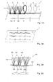
- Fig. 1A shows, in cross-sectional view, a piece of artificial grass 1 according to the invention, provided with a relatively thin, flexible carrier 3 and a series of fibers 4, projecting from the carrier 3 in bunches, or "tufts" 5.
- the fibers 4 have a flat, elongated form, in order to resemble real grass, but can, naturally, have many other forms.
- the fibers 4 are manufactured from a thermoplastic material, such as, for instance, polyester, polyamide, polypropylene, polyethylene or combinations thereof.
- the tufts 5 are formed by bundling a number of fibers 4 into a strand 6, and to then draw this strand through the carrier 3 by means of techniques known per se such as, for instance, tufting, weaving or knitting.
- loops L are then formed which, subsequently, can be cut open as schematically shown in Fig. 1A, at the right hand side in interrupted lines and with cutting lines S.
- strands 6 can be weaved through two carriers 3 placed one at a distance above the other (this is known as so-called two-layer weaving), wherein between the carriers 3, "loops" L are formed, which can then be cut through halfway so that two carriers 3 with tufts 5 are obtained.
- each tuft 5 will each time be connected to at least one other tuft 5, via a strand part 8, which strand part 8 extends at the underside of the carrier 3, between the respective tufts 5 (see also Fig. 1B).
- the fibers 4 of these strand part 8 are fused together at least locally, in a manner to be further described.
- the carrier 3 can be a non-woven material, for instance felt or a synthetic plastic, but can also be a woven, knitted or foamed material.
- the carrier 3 can further be manufactured from natural or synthetic material.
- synthetic material preferably, a thermoplastic material is chosen, for instance polyethylene or polyester. As a result, the fibers can be fused well to the underside of the carrier 3.
- a supporting layer 7 can be provided (as shown in Fig. 1A, but, for the sake of clarity, omitted in Fig. 1B).
- This supporting layer 7 can for instance be manufactured from a relatively thick, resilient material such as for instance felt, rubber or latex.
- the supporting layer 7 is manufactured from a foamed plastic, for instance polyethylene foam.
- foamed layer 7 has good damping and insulating properties.
- the foam preferably has a closed cell structure, in order to prevent sponge action and damage through freezing.
- the supporting layer 7 can for instance be connected to the carrier 3 through gluing or fusing, in particular flame laminating. If desired, the supporting layer 7 and carrier 3 can be provided with openings for draining (rain)water. In an alternative embodiment, the carrier 3 and supporting layer 7 can be replaced by one single layer, in which the strand fibers 4 are provided and secured in the above-mentioned manner. Naturally, the supporting layer 7 can also be omitted so that a very thin, light product is obtained. In that case, the supporting layer 7 can be supplied additionally, as loose underlying layer.
- the artificial grass 1 can be furnished in strips (on a roll) or in tile-form.
- fastening means 9 can be provided such, as for instance, Velcro tape, tape, press studs or magnet strips, for anchoring the artificial grass to an underground. If desired, this underground can be provided with complementary fastening means.
- ballast or filler means can be used in the form of, for instance, sand or synthetic granules, which can be scattered over the artificial grass 1 in order to weight the artificial grass and thus keep it in place.
- Such filler means offer as additional advantage that it helps the "blades of grass", at least the tufts 5 and the separate fibers 4 therein, to stay upright.
- Fig. 3 schematically shows an apparatus 10 according to the invention for manufacturing artificial grass 1 as described hereinabove.
- the apparatus 10 shown comprises, from left to right, a first reel 12 for the supply of carrier material 3, a series of second reels 13 a-n for the supply of loose fibers 4 (alternatively, the fibres 4 can be supplied as strand 6, from a single reel, not shown), a tufting station 14 for drawing the strand 6 through the carrier 3 and, subsequently, cutting open S the formed loops L, and a securing unit 15 for securing the tufts 5 in or to the carrier 3.
- a laminating station 16 is provided for applying a supporting layer 7 to the carrier 3.
- the laminating station 16 is provided with a third reel 17 for the supply of supporting material 7, heating means 18 for heating the supporting material 7, and pressure means 19 in the form of a pair of rollers with which the heated supporting layer 7 can be pressed against the carrier 3 (which process, in jargon, is called 'flame laminating').
- the supporting layer 7 can be fastened to the carrier 3 in other manners, for instance through gluing.
- the laminating station 16 can thereto be adjusted accordingly.
- the supporting layer 7 can also be provided in a later stage or be completely omitted.
- the apparatus 10 can further comprise a station (not shown) for applying fastening means 9 to an underside of the artificial grass 1, for instance Velcro tape or tape as shown in Fig. 1A.
- a fourth reel can be provided (not shown) for storing the produced artificial grass 1 on a roll, or a cutting and stacking station (not shown either) for cutting the artificial grass to size, for instance into tiles, and then stacking it.
- the tufting station 14 is provided with means, in particular one or more needles 20, for drawing the supplied strand of fibers 6 through the carrier 3, for instance through tufting, weaving, knitting or in other manners (known per se). Further, diverting means can be provided (not shown) around which the strands 6 can be guided in order to thus form loops L.
- the tufting station 14 further comprises cutting means 22 to cut the formed loops L open or through, so that tufts 5 are obtained.
- drive means, guiding means, buffers and/or storing reels can be provided in order to lead the carrier 3 and the fibers 6 along these stations at a desired pace.
- the stations can also be designed as autonomous stations, along which the artificial grass can be guided in successive steps, separated in place and time.
- the securing unit 15 comprises heating means 24 for heating, at least locally, the fibers 4 in the strand part 8 at the underside of the carrier 3, and pressure means 25 for pressing the heated fibers 4 together so that they fuse together.
- heating means 24 for heating, at least locally, the fibers 4 in the strand part 8 at the underside of the carrier 3, and pressure means 25 for pressing the heated fibers 4 together so that they fuse together.
- the pressure means 25 comprise a pressure roller 26, arranged under the carrier 3, and two counter pressure rollers 28, arranged above the carrier 3, on both sides of the pressure roller 26 or, viewed in travelling direction V of the carrier 3, in front of and behind the pressure roller 26.
- a force F D can be applied to the underside of the carrier 3, while with the pressure rollers 26, two counterforces Fc can be applied to the top side of the carrier 3 which, together, are as great as the force F D mentioned, but opposite in direction.
- the pressure roller 26 is provided with a heated shell, so that the pressure roller 26 can also function as heating means 24.
- the underside of carrier 3 is simultaneously heated and pressed-on by pressure roller 26.
- the fibers 4 in the strand parts 8 will fuse in a manner as shown in Fig. 1B, that is, without appreciable (plastic) deformation.
- An advantage of this embodiment is that a very limited pressure can suffice.
- a counter pressure applied by the counter pressure rollers 28 acts on a "cold" part of the carrier 3, so that this counter pressure (which is already small) will not occasion appreciable deformation at the tufts 5.
- the virtually undeformed, fused fibers 4 can form projecting ridges at the underside of the carrier 3, (provided that the tufts 5 are arranged in rows) between which, in use, channels can be formed for draining rainwater.
- the securing unit 15 can be designed as shown in Fig. 4B, while parts corresponding to Fig. 4A are indicated with corresponding reference numerals, increased by 100.
- the pressure means 125 comprise a pair of rollers disposed one above the other, with which two equally great, but opposing forces F D , Fc can be applied to an underside or top side, respectively, of the carrier 103.
- the heating means 124 are arranged in front of the pressure means 125, and can comprise, for instance, an infrared station or a heated roller.
- the carrier 103 is guided by an underside along the heating means 124 so that fibers extending against this underside are heated to above their melting temperature. Thereupon, the carrier 103 is guided along the pair of rollers 125, so that the heated fibers 104 are pressed against each other and against the carrier 103.
- the fibers 104 can then, if desired, be flattened, as shown in Figs. 2A, B (by setting a sufficiently high roller pressure). The fusing together ensures that no individual fibers 104 can be pulled loose, while the flattened form ensures that the tufts 105 cannot be pulled through the carrier 103 from a top side of this carrier 103.
- the carrier 103 is preferably manufactured from heat-insulating material or provided, at a top side, with a layer of heat insulating material, so that the tufts 105 are not heated, or only to a limited extent (through heat conduction from the underside of the carrier 103). It is further preferred that the set pressure force F D,C is kept as low as possible so that the tufts 105 are not deformed by this pressure force. Also, the top roller can be cooled in order to cool the tufts 5, should they nevertheless have heated to a limited extent.
Abstract
Description
- The invention relates to a method for manufacturing artificial grass.
- As a rule, artificial grass is manufactured by drawing strands composed of loose, or substantially loose fibers through a carrier, for instance through tufting, weaving or knitting, in a manner such that at a top side of the carrier, loops are formed. These loops are then cut open so that so-called "tufts" are obtained, each composed of a small bundle of loose, or substantially loose fibers. Here, each tuft is connected to at least one other tuft, via a strand part extending against the underside of the carrier. In order to secure the tufts to the carrier, these strand parts are usually fastened against the underside of the carrier by applying a layer of latex to this underside. In use, this latex layer can also serve as resilient, smoothening and/or damping layer.
- A drawback of this known method of securing is that latex does not adhere well to all materials, which limits the choice as to the fiber and carrier materials. Moreover, the layer of latex will only adhere to the lowermost fibers in the respective strand parts. The other fibers, located closer to the carrier, are, at most, no more than clamped in between the latex layer and the carrier. As a result, these fibers can easily become detached and/or be pulled from the carrier, so that bare spots can form. This problem increases according as the number of fibers in the strand is larger. Further, relatively much latex is required which is expensive and leads to a relatively heavy product. Furthermore, latex has the property that it ages and, in the long run, pulverizes, whereby its securing effect is lost.
- The object of the invention is to provide a method for manufacturing artificial grass, wherein at least a part of the drawbacks of the known method are obviated. In particular, the invention contemplates providing a method for securing the tufts of the artificial grass to a carrier without utilizing latex. To that end, a method according to the invention is characterized by the features of
claim 1. - By manufacturing the fibers from a thermoplastic material, and by fusing the fibers of the respective strand parts together, the individual fibers can no longer be pulled loose. Moreover, the fused part can function as a sort of physical anchor which catches under the carrier and thus prevents an entire tuft from being pulled from the carrier from the top side. Fusing merely requires heat and some pressure, no additional auxiliary substances. As a result, a particularly light end product can be obtained.
- In principle, the fibers in the respective strand parts need only be fused locally, that is, over a limited part of their lengths. In order to prevent tufts from shifting relative to the carrier, it is preferred to fuse the fibers at least adjacent the location where these tufts are drawn through the carrier for forming this physical anchor at that location. Naturally, the fibers can also be fused over the entire length of the respective strand parts.
- It is noted that in this description, the term "fibers" is used as a collective term for all materials from which artificial grass can be formed in the above-mentioned manner, that is, by drawing a strand of these fibers through a carrier. Here, yarns, threads and/or (mono)filaments can for instance be considered. These "fibers" may be included loosely in the strand but can also be mutually connected, at least partly. For instance, the fibers may be formed from defibrated (partly cut loose) band material, or the strands can, at least partly, be plaited or twisted. Further, the strands can be composed of different types of fibers.
- In an embodiment according to the invention, the fibers of adjoining strand parts are fused head to tail. As a result, at the underside of the carrier, rows and/or a network of fused fibers are/is obtained, so that tufts can be prevented even better from being pulled from the carrier from a top side. Furthermore, the fused rows can form projecting ridges between which, in use, when the artificial grass is placed on an underground, channels can be formed for drainage of, for instance, rainwater.
- In a further embodiment according to the invention, the strand parts, at least a number of fibers thereof, are, at least locally, fused to an underside of the carrier. As a result, the tufts are secured to the carrier in all directions and pulling the tufts and/or fibers loose from an underside of the carrier is also prevented.
- In further elaboration, the fibers are fused by heating and subsequently pressing them together. Here, the heating temperature is preferably relatively high, in particular approximately 10° to 50° higher than a melting temperature of the fibers, so that these fibers can fuse under relatively limited pressure. The carrier can be guided along, successively, an infrared station or a heated surface and then be guided along a pair of rollers. If desired, a roller contacting the underside of the carrier can be heated so that it can simultaneously serve as heating means. In addition, a roller contacting the top side of the carrier can be cooled, in order to cool the tufts and thus minimize the deforming effect of a pressure applied by this roller to the tufts.
- In a further embodiment, heating and pressing-on the fibers takes place mainly at the underside of the carrier. To that end, the carrier can be guided by an underside along a heat source, for instance a heated roller, and be pressed against this heat source with the aid of counter pressure means, these counter pressure rollers preferably engaging a part of the carrier which is substantially unheated or has already cooled. To that end, the counter pressure means can be arranged at a distance from the heat source, viewed in travelling direction of the carrier. In addition or alternatively, the counter pressure means can be provided with cooling means. As a result, the deforming influence of this counter pressure on the carrier can be minimized so that formation of nap can be prevented. Nap formation is the phenomenon whereby, under the influence of heat, pressure and internal stresses, tufts assume a preferential direction. This process is irreversible.
- In a further embodiment, a supporting layer can be provided against the underside of the carrier, which layer can be manufactured from, for instance, a resilient, damping material, for instance, foamed plastic. This supporting layer and the carrier can be glued or melted together, while fusion of the supporting layer can take place in a manner comparable to the fusion of the fibers, or even, at least partly, simultaneously therewith. Further, against an underside of the carrier, fastening means can be provided such as for instance Velcro tape, adhesive tape, press studs or the like, preferably detachable fastening means. With these, the artificial grass can be fastened to an underground in a simple manner. The artificial grass can for instance be supplied in strips (on the roll) or as tiles, and can be suited for use indoors as well as outdoors.
- The invention further relates to an apparatus for manufacturing artificial grass, formed from strands of thermoplastic fibers drawn through a carrier. The apparatus is then provided with heating means for heating fibers extending at an underside of the carrier, and pressure means for pressing these heated fibers together. As a result, the fibers will fuse in situ and individual fibers are thus prevented from being pulled from the carrier. Moreover, the greater the set pressure is, the more the fibers will deform, in particular be flattened, so that at the location of the fusion, physical anchors will be formed (at the underside of the carrier) preventing entire strands from being pulled from the carrier from the top side. These flattened parts furthermore have a relatively large surface so that they can adhere well to the carrier.
- In an advantageous embodiment, the heating means and pressure means are at least partly combined in the form of a heated pressure roller along which the carrier can be guided by an underside. Here, a number of guiding rollers or counter pressure rollers can be provided for having the carrier lie at a particular pressure against this pressure roller. It is preferred that these counter pressure rollers are arranged, viewed in travelling direction of the carrier, in front of and behind the pressure roller, at such a distance from this pressure roller that they engage a substantially unheated carrier part.
- The invention further relates to artificial grass, provided with a carrier and strands of thermoplastic fibers drawn therethrough, which fibers are fused together, at least locally, at an underside of the carrier in a manner such that the individual fibers are secured against pulling loose from a top side of the carrier.
- Against the underside of the carrier, further, one or more supporting layers can be provided, in order to give the artificial grass the desired properties, for instance in the field of damping, resilience, weight, insulation, watertightness et cetera. Thus, depending on the intended field of use and associated requirements for use, different supporting layers can be provided under the carrier.
- In the further subclaims, further advantageous embodiments are described of a method and apparatus according to the invention, as well as artificial grass manufactured therewith. In clarification, exemplary embodiments of a method, apparatus and artificial grass according to the invention will be further elucidated with reference to the drawing. In the drawing:
- Fig. 1A shows, in cross-sectional view, a first embodiment of a piece of artificial grass according to the invention;
- Fig. 1B shows, in bottom view, the artificial grass according to Fig. 1A, with removed supporting layer;
- Figs. 2A,B show, in cross-sectional view and bottom view, respectively, an alternative embodiment of a piece of artificial grass according to the invention;
- Fig. 3 schematically shows, in side view, an apparatus for manufacturing artificial grass according to the invention; and
- Figs. 4A, B show two exemplary embodiments of a securing unit according to the invention, for fusing the fibers together, resulting in artificial grass according to Figs. 1A, B and artificial grass according to Figs. 2A,B, respectively.
- Fig. 1A shows, in cross-sectional view, a piece of
artificial grass 1 according to the invention, provided with a relatively thin,flexible carrier 3 and a series offibers 4, projecting from thecarrier 3 in bunches, or "tufts" 5. In the exemplary embodiment shown, thefibers 4 have a flat, elongated form, in order to resemble real grass, but can, naturally, have many other forms. Thefibers 4 are manufactured from a thermoplastic material, such as, for instance, polyester, polyamide, polypropylene, polyethylene or combinations thereof. Thetufts 5 are formed by bundling a number offibers 4 into astrand 6, and to then draw this strand through thecarrier 3 by means of techniques known per se such as, for instance, tufting, weaving or knitting. At a top side of thecarrier 3, loops L are then formed which, subsequently, can be cut open as schematically shown in Fig. 1A, at the right hand side in interrupted lines and with cutting lines S. - Alternatively,
strands 6 can be weaved through twocarriers 3 placed one at a distance above the other (this is known as so-called two-layer weaving), wherein between thecarriers 3, "loops" L are formed, which can then be cut through halfway so that twocarriers 3 withtufts 5 are obtained. - In all cases, each
tuft 5 will each time be connected to at least oneother tuft 5, via astrand part 8, whichstrand part 8 extends at the underside of thecarrier 3, between the respective tufts 5 (see also Fig. 1B). Withartificial grass 1 according to the invention, thefibers 4 of thesestrand part 8 are fused together at least locally, in a manner to be further described. - The
carrier 3 can be a non-woven material, for instance felt or a synthetic plastic, but can also be a woven, knitted or foamed material. Thecarrier 3 can further be manufactured from natural or synthetic material. In the case of synthetic material, preferably, a thermoplastic material is chosen, for instance polyethylene or polyester. As a result, the fibers can be fused well to the underside of thecarrier 3. - Against the underside of the
carrier 3, a supportinglayer 7 can be provided (as shown in Fig. 1A, but, for the sake of clarity, omitted in Fig. 1B). This supportinglayer 7 can for instance be manufactured from a relatively thick, resilient material such as for instance felt, rubber or latex. In an advantageous embodiment, the supportinglayer 7 is manufactured from a foamed plastic, for instance polyethylene foam. Such a foamedlayer 7 has good damping and insulating properties. When the artificial grass is intended for outdoor use, the foam preferably has a closed cell structure, in order to prevent sponge action and damage through freezing. - Depending on the material from which the
carrier 3 and the supportinglayer 7 are manufactured, the supportinglayer 7 can for instance be connected to thecarrier 3 through gluing or fusing, in particular flame laminating. If desired, the supportinglayer 7 andcarrier 3 can be provided with openings for draining (rain)water. In an alternative embodiment, thecarrier 3 and supportinglayer 7 can be replaced by one single layer, in which thestrand fibers 4 are provided and secured in the above-mentioned manner. Naturally, the supportinglayer 7 can also be omitted so that a very thin, light product is obtained. In that case, the supportinglayer 7 can be supplied additionally, as loose underlying layer. - The
artificial grass 1 can be furnished in strips (on a roll) or in tile-form. Against an underside of theartificial grass 1, fastening means 9 can be provided such, as for instance, Velcro tape, tape, press studs or magnet strips, for anchoring the artificial grass to an underground. If desired, this underground can be provided with complementary fastening means. In addition or alternatively, ballast or filler means can be used in the form of, for instance, sand or synthetic granules, which can be scattered over theartificial grass 1 in order to weight the artificial grass and thus keep it in place. Such filler means offer as additional advantage that it helps the "blades of grass", at least thetufts 5 and theseparate fibers 4 therein, to stay upright. - Fig. 3 schematically shows an
apparatus 10 according to the invention for manufacturingartificial grass 1 as described hereinabove. To that end, theapparatus 10 shown comprises, from left to right, afirst reel 12 for the supply ofcarrier material 3, a series of second reels 13a-n for the supply of loose fibers 4 (alternatively, thefibres 4 can be supplied asstrand 6, from a single reel, not shown), atufting station 14 for drawing thestrand 6 through thecarrier 3 and, subsequently, cutting open S the formed loops L, and a securingunit 15 for securing thetufts 5 in or to thecarrier 3. In the exemplary embodiment shown, further, alaminating station 16 is provided for applying a supportinglayer 7 to thecarrier 3. To that end, thelaminating station 16 is provided with athird reel 17 for the supply of supportingmaterial 7, heating means 18 for heating the supportingmaterial 7, and pressure means 19 in the form of a pair of rollers with which the heated supportinglayer 7 can be pressed against the carrier 3 (which process, in jargon, is called 'flame laminating'). Naturally the supportinglayer 7 can be fastened to thecarrier 3 in other manners, for instance through gluing. Thelaminating station 16 can thereto be adjusted accordingly. The supportinglayer 7 can also be provided in a later stage or be completely omitted. Theapparatus 10 can further comprise a station (not shown) for applying fastening means 9 to an underside of theartificial grass 1, for instance Velcro tape or tape as shown in Fig. 1A. Further, a fourth reel can be provided (not shown) for storing the producedartificial grass 1 on a roll, or a cutting and stacking station (not shown either) for cutting the artificial grass to size, for instance into tiles, and then stacking it. - The
tufting station 14 is provided with means, in particular one ormore needles 20, for drawing the supplied strand offibers 6 through thecarrier 3, for instance through tufting, weaving, knitting or in other manners (known per se). Further, diverting means can be provided (not shown) around which thestrands 6 can be guided in order to thus form loops L. Thetufting station 14 further comprises cutting means 22 to cut the formed loops L open or through, so thattufts 5 are obtained. - Further, between the different stations mentioned, naturally, drive means, guiding means, buffers and/or storing reels (none shown) can be provided in order to lead the
carrier 3 and thefibers 6 along these stations at a desired pace. The stations can also be designed as autonomous stations, along which the artificial grass can be guided in successive steps, separated in place and time. - The securing
unit 15 comprises heating means 24 for heating, at least locally, thefibers 4 in thestrand part 8 at the underside of thecarrier 3, and pressure means 25 for pressing theheated fibers 4 together so that they fuse together. Hereinbelow, two possible embodiments of a securingunit 15 according to the invention will be described with reference to Figs. 4A and B, with which anartificial grass 1 according to Figs 1A,B and an artificial grass to be further described according to Figs. 2A,B, respectively, can be manufactured. - In the embodiment according to Fig. 4A, the pressure means 25 comprise a
pressure roller 26, arranged under thecarrier 3, and twocounter pressure rollers 28, arranged above thecarrier 3, on both sides of thepressure roller 26 or, viewed in travelling direction V of thecarrier 3, in front of and behind thepressure roller 26. By means of thepressure roller 26, a force FD can be applied to the underside of thecarrier 3, while with thepressure rollers 26, two counterforces Fc can be applied to the top side of thecarrier 3 which, together, are as great as the force FD mentioned, but opposite in direction. Thepressure roller 26 is provided with a heated shell, so that thepressure roller 26 can also function as heating means 24. - In this embodiment, the underside of
carrier 3 is simultaneously heated and pressed-on bypressure roller 26. As a result, thefibers 4 in thestrand parts 8 will fuse in a manner as shown in Fig. 1B, that is, without appreciable (plastic) deformation. An advantage of this embodiment is that a very limited pressure can suffice. Furthermore, a counter pressure applied by thecounter pressure rollers 28 acts on a "cold" part of thecarrier 3, so that this counter pressure (which is already small) will not occasion appreciable deformation at thetufts 5. The virtually undeformed, fusedfibers 4 can form projecting ridges at the underside of thecarrier 3, (provided that thetufts 5 are arranged in rows) between which, in use, channels can be formed for draining rainwater. - In an alternative embodiment, the securing
unit 15 can be designed as shown in Fig. 4B, while parts corresponding to Fig. 4A are indicated with corresponding reference numerals, increased by 100. In this embodiment, the pressure means 125 comprise a pair of rollers disposed one above the other, with which two equally great, but opposing forces FD, Fc can be applied to an underside or top side, respectively, of thecarrier 103. The heating means 124 are arranged in front of the pressure means 125, and can comprise, for instance, an infrared station or a heated roller. - In this embodiment, the
carrier 103 is guided by an underside along the heating means 124 so that fibers extending against this underside are heated to above their melting temperature. Thereupon, thecarrier 103 is guided along the pair ofrollers 125, so that theheated fibers 104 are pressed against each other and against thecarrier 103. Thefibers 104 can then, if desired, be flattened, as shown in Figs. 2A, B (by setting a sufficiently high roller pressure). The fusing together ensures that noindividual fibers 104 can be pulled loose, while the flattened form ensures that thetufts 105 cannot be pulled through thecarrier 103 from a top side of thiscarrier 103. - With this embodiment, the
carrier 103 is preferably manufactured from heat-insulating material or provided, at a top side, with a layer of heat insulating material, so that thetufts 105 are not heated, or only to a limited extent (through heat conduction from the underside of the carrier 103). It is further preferred that the set pressure force FD,C is kept as low as possible so that thetufts 105 are not deformed by this pressure force. Also, the top roller can be cooled in order to cool thetufts 5, should they nevertheless have heated to a limited extent. - By profiling the pressure means in a suitable manner, it can be ensured that, at some locations, the
fibers fibers - The invention is not limited in any manner to the exemplary embodiments represented in the description and the drawing. All combinations of (parts of) embodiments described and/or shown are understood to fall within the inventive concept. Furthermore, many variations thereon are possible within the framework of the invention as set forth in the following claims.
Claims (21)
- A method for manufacturing artificial grass, wherein in a previous production step a strand composed of loose, or substantially loose fibers is drawn through a carrier in a manner such that at the top side of this carrier, loops are formed which at some moment or other in the production process can be cut open for forming tufts, each tuft being connected to at least one other tuft via a strand part extending along an underside of the carrier, characterized in that the strands are manufactured from thermoplastic material and the fibers of the respective strand parts are fused together, at least locally.
- A method according to claim 1, wherein the fibers of adjoining strand parts are fused head to tail.
- A method according to claim 1 or 2, wherein the strand parts are fused to an underside of the carrier.
- A method according to any one of the preceding claims, wherein the fusing of the fibers is done by heat and pressure.
- A method according to claim 4, wherein pressure is applied to heated fibers, and wherein a counter pressure or reaction pressure to be applied to the carrier is applied to a part of the carrier that is substantially unheated or has already cooled.
- A method according to any one of the preceding claims, wherein the carrier is guided by an underside along heating means and pressure means.
- A method according to claim 6, wherein the carrier is guided by a top side along counter pressure means, which are arranged directly above the pressure means.
- A method according to claim 6, wherein the carrier is guided by a top side along counter pressure means, which, viewed in travelling direction of the carrier, are arranged at a considerable distance in front of and behind the heating means, so that a counter pressure applied by these counter pressure means to the carrier acts on a substantially unheated carrier part.
- A method according to any one of claims 6 - 8, wherein the pressure means are heated and thus, simultaneously, function as heating means.
- A method according to any one of the preceding claims, wherein, to the underside of the carrier, a supporting layer is applied which is preferably manufactured from a resilient material, and which is fastened to the carrier by, for instance, gluing or fusion, in particular flame laminating.
- An apparatus for manufacturing artificial grass that is formed from strands of thermoplastic fibers drawn through a carrier, wherein the apparatus is provided with heating means for heating fibers extending at an underside of the carrier and pressure means for pressing these heated fibers against each other so that, at that location, these fibers fuse together.
- An apparatus according to claim 11, wherein the heating means comprise a heated roller.
- An apparatus according to claim 11 or 12, wherein the heating means are designed for heating the fibers to a temperature which is higher than a melting point of these fibers.
- An apparatus according to any one of claims 11- 13, wherein the pressure means comprise at least one pressure roller and at least one counter pressure roller, designed for applying pressure to an underside and a top side of the carrier.
- An apparatus according to claim 14, wherein one pressure roller and two counter pressure rollers are provided, while the counter pressure rollers are arranged, viewed in travelling direction of the carrier, in front of and behind the pressure roller and are designed for forcing the carrier against the pressure roller.
- Artificial grass comprising a carrier, provided with tufts, formed from strands of thermoplastic fibers drawn through the carrier, wherein each tuft is connected to at least one other tuft, via a strand part extending under the carrier, while the fibers of the respective strand part are fused together at least locally.
- Artificial grass according to claim 16, wherein the fibers are fused together such that the fused parts form physical anchors, preventing the fibers and/or tufts from being pulled loose from a top side of the carrier.
- Artificial grass according to claim 16 or 17, wherein against the underside of the carrier a supporting layer is provided, preferably manufactured from a relatively resilient material.
- Artificial grass according to any one of claims 16 - 18, wherein the carrier and the optional supporting layer are provided with drainage openings for water.
- Artificial grass according to any one of claims 16 - 19, wherein fastening means are provided for fastening the artificial grass to an underground.
- Artificial grass according to any one of claims 16 - 20, wherein the artificial grass is strip-shaped or tile-shaped.
Applications Claiming Priority (1)
| Application Number | Priority Date | Filing Date | Title |
|---|---|---|---|
| NL1028626A NL1028626C2 (en) | 2005-03-24 | 2005-03-24 | Method and device for manufacturing artificial grass. |
Publications (2)
| Publication Number | Publication Date |
|---|---|
| EP1705292A1 true EP1705292A1 (en) | 2006-09-27 |
| EP1705292B1 EP1705292B1 (en) | 2009-09-09 |
Family
ID=35207850
Family Applications (1)
| Application Number | Title | Priority Date | Filing Date |
|---|---|---|---|
| EP06075692A Not-in-force EP1705292B1 (en) | 2005-03-24 | 2006-03-24 | Method for manufacturing artificial grass |
Country Status (4)
| Country | Link |
|---|---|
| EP (1) | EP1705292B1 (en) |
| AT (1) | ATE442483T1 (en) |
| DE (1) | DE602006009005D1 (en) |
| NL (1) | NL1028626C2 (en) |
Cited By (24)
| Publication number | Priority date | Publication date | Assignee | Title |
|---|---|---|---|---|
| EP1892331A1 (en) * | 2006-08-18 | 2008-02-27 | Mondo S.p.A. | Synthetic grass turf and related manufacturing method |
| EP1916330A1 (en) | 2006-10-24 | 2008-04-30 | Maltzahn Carpets GmbH | Method for manufacturing a carpet and carpet manufactured according to this method |
| NL1032876C2 (en) * | 2006-11-16 | 2008-05-19 | Ten Cate Thiolon Bv | Composite artificial grass fiber and method for manufacturing such an artificial grass fiber. |
| WO2008077559A1 (en) * | 2006-12-22 | 2008-07-03 | Nv Michel Van De Wiele | Artificial turf |
| WO2008077544A1 (en) * | 2006-12-22 | 2008-07-03 | Nv Michel Van De Wiele | Artificial turf and method for producing a turf of this type |
| EP2011919A1 (en) | 2007-07-06 | 2009-01-07 | Mondo S.p.A. | Flooring material and methods of manufacture |
| WO2009011569A1 (en) * | 2007-07-17 | 2009-01-22 | Hugo De Vries | Method and device for manufacturing artificial turf |
| EP2172589A1 (en) * | 2008-09-25 | 2010-04-07 | N.T.T. di Adriano Moioli & C. S.A.S. | Synthetic mat and process for the production of said mat |
| WO2012076348A3 (en) * | 2010-12-06 | 2012-08-02 | Niaga Bv | A method to produce a pile textile product and a textile product resulting from the same |
| US20130101756A1 (en) * | 2011-05-31 | 2013-04-25 | Kolonglotech, Inc. | Artificial turf structure and apparatus and method for manufacturing the same |
| WO2014032102A1 (en) * | 2012-08-30 | 2014-03-06 | Alltex Specialty Products Pty Ltd | Artificial sports surface |
| WO2014198732A1 (en) | 2013-06-10 | 2014-12-18 | Dsm Ip Assets B.V. | Method for producing textile products, products obtainable therefrom and method to reclaim the products |
| DE102014108121A1 (en) * | 2014-06-10 | 2015-12-17 | Kiener Maschinenbau Gmbh | Method for processing a back side of a web material and device for carrying out the method |
| WO2016110547A1 (en) * | 2015-01-09 | 2016-07-14 | Dsm Ip Assets B.V. | A method to manufacture a textile product, a use thereof and a device for applying the method |
| CN105793493A (en) * | 2013-10-04 | 2016-07-20 | 李政旻 | Artificial turf mat and manufacturing apparatus therefor |
| CN106320141A (en) * | 2016-08-19 | 2017-01-11 | 广州傲胜人造草股份有限公司 | Method for manufacturing artificial turf |
| JP2018502239A (en) * | 2015-01-16 | 2018-01-25 | ベーエフエス ユーロプ エンフェー | Fire retardant artificial grass |
| IT201700109023A1 (en) * | 2017-09-28 | 2019-03-28 | Nikolaos Sarris | METHOD OF REALIZING A CARPET IN SYNTHETIC GRASS |
| WO2019093900A1 (en) * | 2017-11-13 | 2019-05-16 | Hugo De Vries | Artificial turf mat and method for manufacture thereof |
| WO2019113560A1 (en) * | 2017-12-08 | 2019-06-13 | Turf Alliance, Llc | Removable artificial turf panel system and method of installing same |
| US20190350437A1 (en) * | 2016-06-17 | 2019-11-21 | Milliken & Company | Floor Mat Having Reduced Tuft Profile |
| US20200071886A1 (en) * | 2018-08-28 | 2020-03-05 | Columbia Insurance Company | Novel Artificial Turf and Methods of Making Same |
| US20210372042A1 (en) * | 2020-05-29 | 2021-12-02 | Columbia Insurance Company | Carpet and method of making same without latex precoat |
| WO2022232013A1 (en) * | 2021-04-25 | 2022-11-03 | Watershed Geosynthetics Llc | Tufted geotextile with understory for shear resistance to hydraulic and dry-flow infill displacement |
Citations (9)
| Publication number | Priority date | Publication date | Assignee | Title |
|---|---|---|---|---|
| DE2105137A1 (en) * | 1971-02-04 | 1972-08-10 | Tegla-Plastik GmbH & Co KG, 8752 Dettingen | Carpet mfr - by a thermoplastic welding method |
| JPS5147166A (en) * | 1974-10-21 | 1976-04-22 | Toyo Linoleum | Pairuno nukenaitafutetsudokaapetsutono seizoho |
| DE2659139A1 (en) * | 1976-12-28 | 1978-07-06 | Dlw Ag | Thermoplastic tuft bonding process - using heat applied momentarily to bond tuft fibres on reverse of carrier fabric without affecting it |
| US4389434A (en) * | 1982-02-12 | 1983-06-21 | Chevron Research Company | Permeable grass-like sport surface with fused glass membrane |
| US4705706A (en) * | 1986-09-16 | 1987-11-10 | Avco Synthetic Turf Production Distribution, Inc. | Tufted carpeting having stitches thermally bonded to backing |
| JPH06146155A (en) * | 1992-10-30 | 1994-05-27 | Sumitomo Rubber Ind Ltd | Artificial turf and its production |
| US5876827A (en) * | 1992-02-10 | 1999-03-02 | Polyloom Corporation Of America | Pile carpet |
| JP2003319864A (en) * | 2002-04-30 | 2003-11-11 | Diatex Co Ltd | Tufted mat made of polyolefin and manufacturing method therefor |
| EP1598476A1 (en) * | 2004-05-21 | 2005-11-23 | Klieverik Heli B.V. | Method for manufacturing a carpet |
-
2005
- 2005-03-24 NL NL1028626A patent/NL1028626C2/en not_active IP Right Cessation
-
2006
- 2006-03-24 DE DE602006009005T patent/DE602006009005D1/en not_active Expired - Fee Related
- 2006-03-24 EP EP06075692A patent/EP1705292B1/en not_active Not-in-force
- 2006-03-24 AT AT06075692T patent/ATE442483T1/en not_active IP Right Cessation
Patent Citations (9)
| Publication number | Priority date | Publication date | Assignee | Title |
|---|---|---|---|---|
| DE2105137A1 (en) * | 1971-02-04 | 1972-08-10 | Tegla-Plastik GmbH & Co KG, 8752 Dettingen | Carpet mfr - by a thermoplastic welding method |
| JPS5147166A (en) * | 1974-10-21 | 1976-04-22 | Toyo Linoleum | Pairuno nukenaitafutetsudokaapetsutono seizoho |
| DE2659139A1 (en) * | 1976-12-28 | 1978-07-06 | Dlw Ag | Thermoplastic tuft bonding process - using heat applied momentarily to bond tuft fibres on reverse of carrier fabric without affecting it |
| US4389434A (en) * | 1982-02-12 | 1983-06-21 | Chevron Research Company | Permeable grass-like sport surface with fused glass membrane |
| US4705706A (en) * | 1986-09-16 | 1987-11-10 | Avco Synthetic Turf Production Distribution, Inc. | Tufted carpeting having stitches thermally bonded to backing |
| US5876827A (en) * | 1992-02-10 | 1999-03-02 | Polyloom Corporation Of America | Pile carpet |
| JPH06146155A (en) * | 1992-10-30 | 1994-05-27 | Sumitomo Rubber Ind Ltd | Artificial turf and its production |
| JP2003319864A (en) * | 2002-04-30 | 2003-11-11 | Diatex Co Ltd | Tufted mat made of polyolefin and manufacturing method therefor |
| EP1598476A1 (en) * | 2004-05-21 | 2005-11-23 | Klieverik Heli B.V. | Method for manufacturing a carpet |
Non-Patent Citations (3)
| Title |
|---|
| DATABASE WPI Section Ch Week 197623, Derwent World Patents Index; Class F05, AN 1976-42934X, XP002353724 * |
| DATABASE WPI Section Ch Week 200422, Derwent World Patents Index; Class A84, AN 2004-230488, XP002353725 * |
| PATENT ABSTRACTS OF JAPAN vol. 018, no. 471 (C - 1245) 2 September 1994 (1994-09-02) * |
Cited By (46)
| Publication number | Priority date | Publication date | Assignee | Title |
|---|---|---|---|---|
| US7670661B2 (en) | 2006-08-18 | 2010-03-02 | Mondo S.P.A. | Synthetic grass turf and related manufacturing method |
| EP1892331A1 (en) * | 2006-08-18 | 2008-02-27 | Mondo S.p.A. | Synthetic grass turf and related manufacturing method |
| EP1916330A1 (en) | 2006-10-24 | 2008-04-30 | Maltzahn Carpets GmbH | Method for manufacturing a carpet and carpet manufactured according to this method |
| NL1032876C2 (en) * | 2006-11-16 | 2008-05-19 | Ten Cate Thiolon Bv | Composite artificial grass fiber and method for manufacturing such an artificial grass fiber. |
| WO2008060143A1 (en) * | 2006-11-16 | 2008-05-22 | Ten Cate Thiolon B.V. | A composite artificial grass fibre as well as a method for manufacturing such an artificial grass fibre. |
| US8182886B2 (en) | 2006-11-16 | 2012-05-22 | Ten Cate Thiolon, B.V. | Composite artificial grass and method for manufacturing same |
| CN101568675B (en) * | 2006-11-16 | 2012-04-18 | 腾凯特塞奥隆公司 | Composite artificial grass fibre as well as a method for manufacturing such artificial grass fibre |
| WO2008077544A1 (en) * | 2006-12-22 | 2008-07-03 | Nv Michel Van De Wiele | Artificial turf and method for producing a turf of this type |
| BE1017428A3 (en) * | 2006-12-22 | 2008-09-02 | Wiele Michel Van De Nv | ARTIFICIAL GRASS MAT AND METHOD FOR MANUFACTURING SUCH MAT. |
| BE1017429A3 (en) * | 2006-12-22 | 2008-09-02 | Wiele Michel Van De Nv | ARTIFICIAL GRASS MATS. |
| EP2122058B1 (en) | 2006-12-22 | 2017-08-23 | NV Michel van de Wiele | Artificial turf and method for producing a turf of this type |
| WO2008077559A1 (en) * | 2006-12-22 | 2008-07-03 | Nv Michel Van De Wiele | Artificial turf |
| EP2011919A1 (en) | 2007-07-06 | 2009-01-07 | Mondo S.p.A. | Flooring material and methods of manufacture |
| US8153227B2 (en) | 2007-07-06 | 2012-04-10 | Mondo S.P.A. | Substrate for floorings such as, for instance, synthetic grass turf, corresponding synthetic grass turf and methods of manufacture |
| WO2009011569A1 (en) * | 2007-07-17 | 2009-01-22 | Hugo De Vries | Method and device for manufacturing artificial turf |
| EP2172589A1 (en) * | 2008-09-25 | 2010-04-07 | N.T.T. di Adriano Moioli & C. S.A.S. | Synthetic mat and process for the production of said mat |
| US9096047B2 (en) | 2010-12-06 | 2015-08-04 | Again Ip B.V. | Method to produce a textile product and a textile product resulting from the same |
| WO2012076348A3 (en) * | 2010-12-06 | 2012-08-02 | Niaga Bv | A method to produce a pile textile product and a textile product resulting from the same |
| US10017899B2 (en) | 2010-12-06 | 2018-07-10 | Again Ip B.V. | Method to produce a pile textile product and a textile product resulting from the same |
| US10422075B2 (en) | 2010-12-06 | 2019-09-24 | Again Ip B.V. | Method to produce a pile textile product and a textile product resulting from the same |
| US20130101756A1 (en) * | 2011-05-31 | 2013-04-25 | Kolonglotech, Inc. | Artificial turf structure and apparatus and method for manufacturing the same |
| JP2013538959A (en) * | 2011-05-31 | 2013-10-17 | コーロン グロテック インコーポレイテッド | Artificial turf structure, manufacturing method thereof, and manufacturing apparatus |
| US9309630B2 (en) | 2012-08-30 | 2016-04-12 | Alltex Specialty Products Pty Ltd | Artificial sports surface |
| GB2519471A (en) * | 2012-08-30 | 2015-04-22 | Alltex Speciality Products Pty Ltd | Artificial sports surface |
| GB2519471B (en) * | 2012-08-30 | 2020-01-01 | Alltex Speciality Products Pty Ltd | Artificial sports surface |
| WO2014032102A1 (en) * | 2012-08-30 | 2014-03-06 | Alltex Specialty Products Pty Ltd | Artificial sports surface |
| AU2013308397B2 (en) * | 2012-08-30 | 2017-08-31 | Alltex Specialty Products Pty Ltd | Artificial sports surface |
| KR20160019503A (en) * | 2013-06-10 | 2016-02-19 | 디에스엠 아이피 어셋츠 비.브이. | Method for producing textile products, products obtainable therefrom and method to reclaim the products |
| WO2014198732A1 (en) | 2013-06-10 | 2014-12-18 | Dsm Ip Assets B.V. | Method for producing textile products, products obtainable therefrom and method to reclaim the products |
| CN105793493A (en) * | 2013-10-04 | 2016-07-20 | 李政旻 | Artificial turf mat and manufacturing apparatus therefor |
| JP2016531720A (en) * | 2013-10-04 | 2016-10-13 | ジュン ミン イ | Artificial grass mat and its manufacturing equipment |
| EP3054053A4 (en) * | 2013-10-04 | 2016-11-02 | Lee Jung Min | Artificial turf mat and manufacturing apparatus therefor |
| AU2014330248B2 (en) * | 2013-10-04 | 2018-02-22 | Field Turf Seung Mok Co., Ltd. | Artificial turf mat and manufacturing apparatus therefor |
| CN105793493B (en) * | 2013-10-04 | 2018-04-27 | 草坪昇穆株式会社 | Pedaline leather packing and its manufacturing equipment |
| DE102014108121A1 (en) * | 2014-06-10 | 2015-12-17 | Kiener Maschinenbau Gmbh | Method for processing a back side of a web material and device for carrying out the method |
| CN107208342A (en) * | 2015-01-09 | 2017-09-26 | 帝斯曼知识产权资产管理有限公司 | The equipment for manufacturing the method, the purposes of the textile product and application this method of textile product |
| WO2016110547A1 (en) * | 2015-01-09 | 2016-07-14 | Dsm Ip Assets B.V. | A method to manufacture a textile product, a use thereof and a device for applying the method |
| JP2018502239A (en) * | 2015-01-16 | 2018-01-25 | ベーエフエス ユーロプ エンフェー | Fire retardant artificial grass |
| US20190350437A1 (en) * | 2016-06-17 | 2019-11-21 | Milliken & Company | Floor Mat Having Reduced Tuft Profile |
| CN106320141A (en) * | 2016-08-19 | 2017-01-11 | 广州傲胜人造草股份有限公司 | Method for manufacturing artificial turf |
| IT201700109023A1 (en) * | 2017-09-28 | 2019-03-28 | Nikolaos Sarris | METHOD OF REALIZING A CARPET IN SYNTHETIC GRASS |
| WO2019093900A1 (en) * | 2017-11-13 | 2019-05-16 | Hugo De Vries | Artificial turf mat and method for manufacture thereof |
| WO2019113560A1 (en) * | 2017-12-08 | 2019-06-13 | Turf Alliance, Llc | Removable artificial turf panel system and method of installing same |
| US20200071886A1 (en) * | 2018-08-28 | 2020-03-05 | Columbia Insurance Company | Novel Artificial Turf and Methods of Making Same |
| US20210372042A1 (en) * | 2020-05-29 | 2021-12-02 | Columbia Insurance Company | Carpet and method of making same without latex precoat |
| WO2022232013A1 (en) * | 2021-04-25 | 2022-11-03 | Watershed Geosynthetics Llc | Tufted geotextile with understory for shear resistance to hydraulic and dry-flow infill displacement |
Also Published As
| Publication number | Publication date |
|---|---|
| NL1028626C2 (en) | 2006-09-27 |
| EP1705292B1 (en) | 2009-09-09 |
| ATE442483T1 (en) | 2009-09-15 |
| DE602006009005D1 (en) | 2009-10-22 |
Similar Documents
| Publication | Publication Date | Title |
|---|---|---|
| EP1705292A1 (en) | Method and apparatus for manufacturing artificial grass | |
| US8557363B2 (en) | Artificial grass turf system | |
| US7670661B2 (en) | Synthetic grass turf and related manufacturing method | |
| US3616137A (en) | Pile weatherstripping with monofilament thermoplastic backing | |
| JP5866717B2 (en) | Artificial turf structure, manufacturing method thereof, and manufacturing apparatus | |
| EP2011919B1 (en) | Flooring material and methods of manufacture | |
| KR101147009B1 (en) | artificial turf structure with improved pullout strength and manufacturing method thereof | |
| DK2419565T3 (en) | Process for forming an artificial grass layer and artificial grass product for use therewith | |
| JPS63139514A (en) | Carpet and its production | |
| CN103628385A (en) | Artificial turf filament and artificial turf system | |
| JP2016531720A (en) | Artificial grass mat and its manufacturing equipment | |
| RU2609217C2 (en) | Method of production tufted carpet | |
| JP5450416B2 (en) | Artificial grass and method and apparatus for forming the same | |
| US20230145157A1 (en) | Artificial turf | |
| JP7374914B2 (en) | Artificial grass mat and its manufacturing method | |
| CN217298514U (en) | Environment-friendly artificial turf | |
| KR20130078104A (en) | Artificial turf and manufacturing method therefor | |
| WO2018032847A1 (en) | Method for manufacturing artificial turf | |
| JPH06146155A (en) | Artificial turf and its production | |
| JPS6314121B2 (en) | ||
| US20200048831A1 (en) | Primary backing for artificial turf, method for its manufacture and artificial turf comprising the primary backing | |
| KR102159611B1 (en) | Manufacturing method of artificial turf mat using pile yarns of various cross-sectional shapes and artificial turf mat produced by the method | |
| WO2012005576A2 (en) | Artificial turf with hook and loop fastening | |
| KR20150057810A (en) | Manufacturing method of artificial turf and the artificial turf made by thereof |
Legal Events
| Date | Code | Title | Description |
|---|---|---|---|
| PUAI | Public reference made under article 153(3) epc to a published international application that has entered the european phase |
Free format text: ORIGINAL CODE: 0009012 |
|
| AK | Designated contracting states |
Kind code of ref document: A1 Designated state(s): AT BE BG CH CY CZ DE DK EE ES FI FR GB GR HU IE IS IT LI LT LU LV MC NL PL PT RO SE SI SK TR |
|
| AX | Request for extension of the european patent |
Extension state: AL BA HR MK YU |
|
| 17P | Request for examination filed |
Effective date: 20070326 |
|
| AKX | Designation fees paid |
Designated state(s): AT BE BG CH CY CZ DE DK EE ES FI FR GB GR HU IE IS IT LI LT LU LV MC NL PL PT RO SE SI SK TR |
|
| 17Q | First examination report despatched |
Effective date: 20070508 |
|
| RAP1 | Party data changed (applicant data changed or rights of an application transferred) |
Owner name: SUBBASE B.V. |
|
| RTI1 | Title (correction) |
Free format text: METHOD FOR MANUFACTURING ARTIFICIAL GRASS |
|
| GRAP | Despatch of communication of intention to grant a patent |
Free format text: ORIGINAL CODE: EPIDOSNIGR1 |
|
| GRAS | Grant fee paid |
Free format text: ORIGINAL CODE: EPIDOSNIGR3 |
|
| GRAA | (expected) grant |
Free format text: ORIGINAL CODE: 0009210 |
|
| AK | Designated contracting states |
Kind code of ref document: B1 Designated state(s): AT BE BG CH CY CZ DE DK EE ES FI FR GB GR HU IE IS IT LI LT LU LV MC NL PL PT RO SE SI SK TR |
|
| REG | Reference to a national code |
Ref country code: GB Ref legal event code: FG4D |
|
| REG | Reference to a national code |
Ref country code: CH Ref legal event code: EP |
|
| REG | Reference to a national code |
Ref country code: IE Ref legal event code: FG4D |
|
| REF | Corresponds to: |
Ref document number: 602006009005 Country of ref document: DE Date of ref document: 20091022 Kind code of ref document: P |
|
| PG25 | Lapsed in a contracting state [announced via postgrant information from national office to epo] |
Ref country code: LT Free format text: LAPSE BECAUSE OF FAILURE TO SUBMIT A TRANSLATION OF THE DESCRIPTION OR TO PAY THE FEE WITHIN THE PRESCRIBED TIME-LIMIT Effective date: 20090909 Ref country code: FI Free format text: LAPSE BECAUSE OF FAILURE TO SUBMIT A TRANSLATION OF THE DESCRIPTION OR TO PAY THE FEE WITHIN THE PRESCRIBED TIME-LIMIT Effective date: 20090909 Ref country code: SE Free format text: LAPSE BECAUSE OF FAILURE TO SUBMIT A TRANSLATION OF THE DESCRIPTION OR TO PAY THE FEE WITHIN THE PRESCRIBED TIME-LIMIT Effective date: 20090909 |
|
| LTIE | Lt: invalidation of european patent or patent extension |
Effective date: 20090909 |
|
| PG25 | Lapsed in a contracting state [announced via postgrant information from national office to epo] |
Ref country code: LV Free format text: LAPSE BECAUSE OF FAILURE TO SUBMIT A TRANSLATION OF THE DESCRIPTION OR TO PAY THE FEE WITHIN THE PRESCRIBED TIME-LIMIT Effective date: 20090909 Ref country code: PL Free format text: LAPSE BECAUSE OF FAILURE TO SUBMIT A TRANSLATION OF THE DESCRIPTION OR TO PAY THE FEE WITHIN THE PRESCRIBED TIME-LIMIT Effective date: 20090909 Ref country code: SI Free format text: LAPSE BECAUSE OF FAILURE TO SUBMIT A TRANSLATION OF THE DESCRIPTION OR TO PAY THE FEE WITHIN THE PRESCRIBED TIME-LIMIT Effective date: 20090909 |
|
| PG25 | Lapsed in a contracting state [announced via postgrant information from national office to epo] |
Ref country code: CY Free format text: LAPSE BECAUSE OF FAILURE TO SUBMIT A TRANSLATION OF THE DESCRIPTION OR TO PAY THE FEE WITHIN THE PRESCRIBED TIME-LIMIT Effective date: 20090909 |
|
| PG25 | Lapsed in a contracting state [announced via postgrant information from national office to epo] |
Ref country code: CZ Free format text: LAPSE BECAUSE OF FAILURE TO SUBMIT A TRANSLATION OF THE DESCRIPTION OR TO PAY THE FEE WITHIN THE PRESCRIBED TIME-LIMIT Effective date: 20090909 Ref country code: IS Free format text: LAPSE BECAUSE OF FAILURE TO SUBMIT A TRANSLATION OF THE DESCRIPTION OR TO PAY THE FEE WITHIN THE PRESCRIBED TIME-LIMIT Effective date: 20100109 Ref country code: RO Free format text: LAPSE BECAUSE OF FAILURE TO SUBMIT A TRANSLATION OF THE DESCRIPTION OR TO PAY THE FEE WITHIN THE PRESCRIBED TIME-LIMIT Effective date: 20090909 Ref country code: ES Free format text: LAPSE BECAUSE OF FAILURE TO SUBMIT A TRANSLATION OF THE DESCRIPTION OR TO PAY THE FEE WITHIN THE PRESCRIBED TIME-LIMIT Effective date: 20091220 Ref country code: EE Free format text: LAPSE BECAUSE OF FAILURE TO SUBMIT A TRANSLATION OF THE DESCRIPTION OR TO PAY THE FEE WITHIN THE PRESCRIBED TIME-LIMIT Effective date: 20090909 Ref country code: PT Free format text: LAPSE BECAUSE OF FAILURE TO SUBMIT A TRANSLATION OF THE DESCRIPTION OR TO PAY THE FEE WITHIN THE PRESCRIBED TIME-LIMIT Effective date: 20100111 |
|
| PG25 | Lapsed in a contracting state [announced via postgrant information from national office to epo] |
Ref country code: SK Free format text: LAPSE BECAUSE OF FAILURE TO SUBMIT A TRANSLATION OF THE DESCRIPTION OR TO PAY THE FEE WITHIN THE PRESCRIBED TIME-LIMIT Effective date: 20090909 |
|
| PG25 | Lapsed in a contracting state [announced via postgrant information from national office to epo] |
Ref country code: AT Free format text: LAPSE BECAUSE OF FAILURE TO SUBMIT A TRANSLATION OF THE DESCRIPTION OR TO PAY THE FEE WITHIN THE PRESCRIBED TIME-LIMIT Effective date: 20090909 |
|
| PLBE | No opposition filed within time limit |
Free format text: ORIGINAL CODE: 0009261 |
|
| STAA | Information on the status of an ep patent application or granted ep patent |
Free format text: STATUS: NO OPPOSITION FILED WITHIN TIME LIMIT |
|
| PG25 | Lapsed in a contracting state [announced via postgrant information from national office to epo] |
Ref country code: DK Free format text: LAPSE BECAUSE OF FAILURE TO SUBMIT A TRANSLATION OF THE DESCRIPTION OR TO PAY THE FEE WITHIN THE PRESCRIBED TIME-LIMIT Effective date: 20090909 |
|
| 26N | No opposition filed |
Effective date: 20100610 |
|
| PG25 | Lapsed in a contracting state [announced via postgrant information from national office to epo] |
Ref country code: MC Free format text: LAPSE BECAUSE OF NON-PAYMENT OF DUE FEES Effective date: 20100331 Ref country code: GR Free format text: LAPSE BECAUSE OF FAILURE TO SUBMIT A TRANSLATION OF THE DESCRIPTION OR TO PAY THE FEE WITHIN THE PRESCRIBED TIME-LIMIT Effective date: 20091210 |
|
| REG | Reference to a national code |
Ref country code: CH Ref legal event code: PL |
|
| REG | Reference to a national code |
Ref country code: FR Ref legal event code: ST Effective date: 20101130 |
|
| PG25 | Lapsed in a contracting state [announced via postgrant information from national office to epo] |
Ref country code: IE Free format text: LAPSE BECAUSE OF NON-PAYMENT OF DUE FEES Effective date: 20100324 Ref country code: FR Free format text: LAPSE BECAUSE OF NON-PAYMENT OF DUE FEES Effective date: 20100331 |
|
| PG25 | Lapsed in a contracting state [announced via postgrant information from national office to epo] |
Ref country code: LI Free format text: LAPSE BECAUSE OF NON-PAYMENT OF DUE FEES Effective date: 20100331 Ref country code: CH Free format text: LAPSE BECAUSE OF NON-PAYMENT OF DUE FEES Effective date: 20100331 Ref country code: DE Free format text: LAPSE BECAUSE OF NON-PAYMENT OF DUE FEES Effective date: 20101001 |
|
| PG25 | Lapsed in a contracting state [announced via postgrant information from national office to epo] |
Ref country code: IT Free format text: LAPSE BECAUSE OF FAILURE TO SUBMIT A TRANSLATION OF THE DESCRIPTION OR TO PAY THE FEE WITHIN THE PRESCRIBED TIME-LIMIT Effective date: 20090909 |
|
| PG25 | Lapsed in a contracting state [announced via postgrant information from national office to epo] |
Ref country code: LU Free format text: LAPSE BECAUSE OF NON-PAYMENT OF DUE FEES Effective date: 20100324 Ref country code: HU Free format text: LAPSE BECAUSE OF FAILURE TO SUBMIT A TRANSLATION OF THE DESCRIPTION OR TO PAY THE FEE WITHIN THE PRESCRIBED TIME-LIMIT Effective date: 20100310 Ref country code: BG Free format text: LAPSE BECAUSE OF FAILURE TO SUBMIT A TRANSLATION OF THE DESCRIPTION OR TO PAY THE FEE WITHIN THE PRESCRIBED TIME-LIMIT Effective date: 20090909 |
|
| PG25 | Lapsed in a contracting state [announced via postgrant information from national office to epo] |
Ref country code: TR Free format text: LAPSE BECAUSE OF FAILURE TO SUBMIT A TRANSLATION OF THE DESCRIPTION OR TO PAY THE FEE WITHIN THE PRESCRIBED TIME-LIMIT Effective date: 20090909 |
|
| PGFP | Annual fee paid to national office [announced via postgrant information from national office to epo] |
Ref country code: GB Payment date: 20130321 Year of fee payment: 8 |
|
| PGFP | Annual fee paid to national office [announced via postgrant information from national office to epo] |
Ref country code: NL Payment date: 20130319 Year of fee payment: 8 |
|
| PGFP | Annual fee paid to national office [announced via postgrant information from national office to epo] |
Ref country code: BE Payment date: 20130320 Year of fee payment: 8 |
|
| REG | Reference to a national code |
Ref country code: NL Ref legal event code: V1 Effective date: 20141001 |
|
| GBPC | Gb: european patent ceased through non-payment of renewal fee |
Effective date: 20140324 |
|
| PG25 | Lapsed in a contracting state [announced via postgrant information from national office to epo] |
Ref country code: GB Free format text: LAPSE BECAUSE OF NON-PAYMENT OF DUE FEES Effective date: 20140324 |
|
| PG25 | Lapsed in a contracting state [announced via postgrant information from national office to epo] |
Ref country code: NL Free format text: LAPSE BECAUSE OF NON-PAYMENT OF DUE FEES Effective date: 20141001 |
|
| PG25 | Lapsed in a contracting state [announced via postgrant information from national office to epo] |
Ref country code: BE Free format text: LAPSE BECAUSE OF NON-PAYMENT OF DUE FEES Effective date: 20140331 |