EP1705051A1 - Low profile overfill limit device with reverse flow capability - Google Patents
Low profile overfill limit device with reverse flow capability Download PDFInfo
- Publication number
- EP1705051A1 EP1705051A1 EP20060005675 EP06005675A EP1705051A1 EP 1705051 A1 EP1705051 A1 EP 1705051A1 EP 20060005675 EP20060005675 EP 20060005675 EP 06005675 A EP06005675 A EP 06005675A EP 1705051 A1 EP1705051 A1 EP 1705051A1
- Authority
- EP
- European Patent Office
- Prior art keywords
- valve
- tank
- vapor
- cap
- vent
- Prior art date
- Legal status (The legal status is an assumption and is not a legal conclusion. Google has not performed a legal analysis and makes no representation as to the accuracy of the status listed.)
- Granted
Links
- 239000002828 fuel tank Substances 0.000 claims abstract description 21
- 230000005484 gravity Effects 0.000 claims abstract description 7
- 239000000463 material Substances 0.000 claims description 10
- 238000004519 manufacturing process Methods 0.000 claims description 3
- 238000003466 welding Methods 0.000 claims description 3
- 238000000034 method Methods 0.000 claims 7
- 238000005304 joining Methods 0.000 claims 2
- 238000013022 venting Methods 0.000 abstract description 2
- 239000000446 fuel Substances 0.000 description 21
- 239000007788 liquid Substances 0.000 description 4
- 230000000717 retained effect Effects 0.000 description 4
- 230000015572 biosynthetic process Effects 0.000 description 3
- 238000001816 cooling Methods 0.000 description 3
- 238000010926 purge Methods 0.000 description 3
- 239000013536 elastomeric material Substances 0.000 description 2
- 238000009434 installation Methods 0.000 description 2
- 239000002184 metal Substances 0.000 description 2
- 230000005494 condensation Effects 0.000 description 1
- 238000009833 condensation Methods 0.000 description 1
- 210000003746 feather Anatomy 0.000 description 1
- 239000000945 filler Substances 0.000 description 1
- 238000012986 modification Methods 0.000 description 1
- 230000004048 modification Effects 0.000 description 1
- 230000000630 rising effect Effects 0.000 description 1
- 238000007789 sealing Methods 0.000 description 1
- 238000003860 storage Methods 0.000 description 1
Images


Classifications
-
- B—PERFORMING OPERATIONS; TRANSPORTING
- B60—VEHICLES IN GENERAL
- B60K—ARRANGEMENT OR MOUNTING OF PROPULSION UNITS OR OF TRANSMISSIONS IN VEHICLES; ARRANGEMENT OR MOUNTING OF PLURAL DIVERSE PRIME-MOVERS IN VEHICLES; AUXILIARY DRIVES FOR VEHICLES; INSTRUMENTATION OR DASHBOARDS FOR VEHICLES; ARRANGEMENTS IN CONNECTION WITH COOLING, AIR INTAKE, GAS EXHAUST OR FUEL SUPPLY OF PROPULSION UNITS IN VEHICLES
- B60K15/00—Arrangement in connection with fuel supply of combustion engines or other fuel consuming energy converters, e.g. fuel cells; Mounting or construction of fuel tanks
- B60K15/01—Arrangement of fuel conduits
-
- F—MECHANICAL ENGINEERING; LIGHTING; HEATING; WEAPONS; BLASTING
- F16—ENGINEERING ELEMENTS AND UNITS; GENERAL MEASURES FOR PRODUCING AND MAINTAINING EFFECTIVE FUNCTIONING OF MACHINES OR INSTALLATIONS; THERMAL INSULATION IN GENERAL
- F16K—VALVES; TAPS; COCKS; ACTUATING-FLOATS; DEVICES FOR VENTING OR AERATING
- F16K24/00—Devices, e.g. valves, for venting or aerating enclosures
- F16K24/04—Devices, e.g. valves, for venting or aerating enclosures for venting only
- F16K24/042—Devices, e.g. valves, for venting or aerating enclosures for venting only actuated by a float
- F16K24/044—Devices, e.g. valves, for venting or aerating enclosures for venting only actuated by a float the float being rigidly connected to the valve element, the assembly of float and valve element following a substantially translational movement when actuated, e.g. also for actuating a pilot valve
-
- B—PERFORMING OPERATIONS; TRANSPORTING
- B60—VEHICLES IN GENERAL
- B60K—ARRANGEMENT OR MOUNTING OF PROPULSION UNITS OR OF TRANSMISSIONS IN VEHICLES; ARRANGEMENT OR MOUNTING OF PLURAL DIVERSE PRIME-MOVERS IN VEHICLES; AUXILIARY DRIVES FOR VEHICLES; INSTRUMENTATION OR DASHBOARDS FOR VEHICLES; ARRANGEMENTS IN CONNECTION WITH COOLING, AIR INTAKE, GAS EXHAUST OR FUEL SUPPLY OF PROPULSION UNITS IN VEHICLES
- B60K15/00—Arrangement in connection with fuel supply of combustion engines or other fuel consuming energy converters, e.g. fuel cells; Mounting or construction of fuel tanks
- B60K15/03—Fuel tanks
- B60K15/035—Fuel tanks characterised by venting means
- B60K15/03519—Valve arrangements in the vent line
-
- B—PERFORMING OPERATIONS; TRANSPORTING
- B60—VEHICLES IN GENERAL
- B60K—ARRANGEMENT OR MOUNTING OF PROPULSION UNITS OR OF TRANSMISSIONS IN VEHICLES; ARRANGEMENT OR MOUNTING OF PLURAL DIVERSE PRIME-MOVERS IN VEHICLES; AUXILIARY DRIVES FOR VEHICLES; INSTRUMENTATION OR DASHBOARDS FOR VEHICLES; ARRANGEMENTS IN CONNECTION WITH COOLING, AIR INTAKE, GAS EXHAUST OR FUEL SUPPLY OF PROPULSION UNITS IN VEHICLES
- B60K15/00—Arrangement in connection with fuel supply of combustion engines or other fuel consuming energy converters, e.g. fuel cells; Mounting or construction of fuel tanks
- B60K15/03—Fuel tanks
- B60K15/04—Tank inlets
-
- F—MECHANICAL ENGINEERING; LIGHTING; HEATING; WEAPONS; BLASTING
- F16—ENGINEERING ELEMENTS AND UNITS; GENERAL MEASURES FOR PRODUCING AND MAINTAINING EFFECTIVE FUNCTIONING OF MACHINES OR INSTALLATIONS; THERMAL INSULATION IN GENERAL
- F16K—VALVES; TAPS; COCKS; ACTUATING-FLOATS; DEVICES FOR VENTING OR AERATING
- F16K17/00—Safety valves; Equalising valves, e.g. pressure relief valves
- F16K17/18—Safety valves; Equalising valves, e.g. pressure relief valves opening on surplus pressure on either side
- F16K17/19—Equalising valves predominantly for tanks
- F16K17/194—Equalising valves predominantly for tanks weight-loaded
-
- Y—GENERAL TAGGING OF NEW TECHNOLOGICAL DEVELOPMENTS; GENERAL TAGGING OF CROSS-SECTIONAL TECHNOLOGIES SPANNING OVER SEVERAL SECTIONS OF THE IPC; TECHNICAL SUBJECTS COVERED BY FORMER USPC CROSS-REFERENCE ART COLLECTIONS [XRACs] AND DIGESTS
- Y10—TECHNICAL SUBJECTS COVERED BY FORMER USPC
- Y10T—TECHNICAL SUBJECTS COVERED BY FORMER US CLASSIFICATION
- Y10T137/00—Fluid handling
- Y10T137/0753—Control by change of position or inertia of system
- Y10T137/0874—Vent opening or closing on tipping container
Definitions
- Small engines as they are often referred to, are widely considered to be engines of less than approximately 50 horsepower (37.2 kilowatts) and are employed for applications such as lawn mowers, garden tractors, portable generating sets and certain marine applications. Small engines for such applications typically have the fuel tank mounted proximate the engine for ease of installation of the engine on the appliance. Such small engine applications generally have a tank disposed for gravity fuel feed to the engine carburetor; however, in certain specialized applications with engines approaching 50 h.p. fuel pumps may be employed.
- Small engine fuel tanks generally have a user removable filler cap or closure which has formed therein a vent passage for permitting make up air to enter the tank as fuel is withdrawn during engine operation to prevent vacuum formation therein and subsequent collapse of the tank.
- Small engines are manufactured in very high volumes in mass production; and, the tooling for the fuel tanks and fuel system and mounting of the tank and the fuel system components on the engines has been a significant expense for the manufacturer of the engines. Furthermore in a significant number of applications for small engines, the space or volume allotted for the engine and fuel tank is highly restricted; and, adding components to the engine and tank, or requiring tank redesign is prohibitively costly.
- valve assembly described herein utilizes a cap with a vapor outlet port therein and which is formed of material weldable to the tank wall with the overflow limiting vapor vent/tipping valve attached to the cap to form a sub assembly.
- the cap is then disposed over the access opening in the tank wall and welded to the surface of the tank wall.
- the valve assembly includes a pressure relief valve permitting the vapor above a predetermined pressure to escape through the cap vent outlet; and, the valve assembly also includes a vacuum relief valve to permit reverse flow in the event of formation of a vacuum in the fuel tank to prevent collapse of the tank.
- the presently described valve assembly thus enables the provision of the necessary functions to retain and limit the escape of fuel vapor from the tank to the atmosphere yet permits flow of vapor under engine operation from the valve outlet which is adapted for connection to either a vapor storage device or the engine air inlet.
- FIG. 1 is a cross section of a small engine fuel tank with the valve assembly described herein mounted through an access opening;
- FIG. 2 is an enlarged view of the valve body subassembly of FIG. 1;
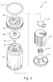
- FIG. 3 is an exploded view of the subassembly of FIG. 2;
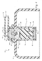
- FIG. 4 is a cross section of a small engine fuel tank illustrating another embodiment.
- a portion of a small engine fuel tank is indicated generally at 10 and has the upper wall structure 12 formed with an access opening 14 therein with an overfill limiting vapor vent/tipping valve assembly indicated generally at 16 disposed with the body 18 thereof extending downwardly through the access only into the interior of the tank.
- the valve body 18 has a valving chamber 20 formed therein which communicates through a vent passage 22 which may be vertically oriented with a valve seat 24 formed at the lower end thereof.
- the upper end of passage 22 has a second valve seat 26 formed thereabout with a valving member 28 seated thereon; and, in the present practice the valve member 28 is formed of a material such as metal to rest against the valve seat 26 under the influence of gravitational forces.
- the weight of member 28 and the diameter of valve seat 26 are chosen such that when a predetermined pressure exists in the valving chamber 20, valve 28 is lifted off of the seat 26 and vapor flows through passage 22.
- Valving chamber 20 has disposed therein a float 30 with a flexible valve member such as strip 32 which may be formed of elastomeric material disposed on the upper surface thereof.
- a flexible valve member such as strip 32 which may be formed of elastomeric material disposed on the upper surface thereof.
- member 32 closes upon valve seat 24 preventing vapor from entering the passage 22.
- Float 30 is retained in valving chamber 20 by a retaining ring 34; and, suitable passages 36 are formed in the valve body to admit liquid fuel into the valving chamber 20.
- the valve body 18 is attached to an upper body portion or insert 40 which may have a generally inverted cup shape with an annular groove 42 formed about the outer periphery thereof, which groove has received therein a sealing ring such as an o-ring 44 which seals about the inner wall 46 of a cap 48 which has an outlet or vapor purge passage 50 formed therein.
- an upper body portion or insert 40 which may have a generally inverted cup shape with an annular groove 42 formed about the outer periphery thereof, which groove has received therein a sealing ring such as an o-ring 44 which seals about the inner wall 46 of a cap 48 which has an outlet or vapor purge passage 50 formed therein.
- the body 18 is attached to the insert 40 by any suitable mechanical expedient, such as snap locking tabs 52.
- the valve body may be formed of material not weldable to the tank for structural integrity; however, the cap 48 is formed of material weldable to the tank such as by sonic or spin welding to form a sub assembly including the valve member 28 and cap 48.
- the sub assembly is retained in the cap by any suitable mechanical expedient such as interference fit or snap locking of annular flange 54 into a groove 56 formed in the cap.
- insert 40 may be formed of material weldable to cap 48 and secured thereto by weldment.
- the rim 58 of the cap with the valve assembled therein may then be secured to the surface of the tank wall 12 by any suitable expedient such as weldment.
- the gravity responsive valve member 28 has a valving chamber 60 formed therein with a vertically oriented flow passage 63 formed in the upper end thereof which passage communicates with the interior of the cap 48 and the purge outlet 50.
- Valving chamber 60 has received therein a feather light valve member 62 which, upon the slightest vapor pressure through passage 22 is moved to the position shown in FIG. 2 to close passage 63; and thereafter valve member 62 maintains the passage 63 closed. Thereafter, as the pressure in the passage 22 rises the gravity valve number 28 is caused to be moved to the upward limit position shown in FIG. 2 and vapor flow therearound is permitted to the purge outlet passage 50.
- valve member 62 In the event of sub-atmospheric pressure in the chamber 20, the valve member 62 is caused to move downwardly opening passage 63 and permitting reverse flow into passage 50 and into the fuel tank. Thus, valve 62 permits make up air to enter the fuel tank as liquid fuel is withdrawn during engine operation; or, in the event of cooling of the vapor and formation of a vacuum in the tank while the engine is shut down.
- FIG. 4 another embodiment is indicated generally at 70 in which an upper portion 72 of the fuel tank wall structure has formed integrally therewith as one piece a valve body 74 which extends inwardly from the tank wall structure and defines a valving chamber 76 with a vertically oriented vent passage 78 through the wall structure of the tank.
- Passage 78 has a valve seat 80 formed on the lower end thereof with a second valve seat 82 formed about the upper end thereof.
- Valving chamber 76 has disposed therein a float 84 which is retained by a retaining member 86 disposed in the lower end of the chamber 76; and, a bias spring 88 is disposed between the lower end of the float 84 and the retaining member 86 for biasing the float in an upward direction.
- spring 88 may be calibrated to assist the buoyancy of the float 84.
- the upper end of the float has disposed thereon a relatively thin flexible valve member 90 which may be formed of elastomeric material and which is operative upon upward movement of the float to close against valve seat 80 at the desired liquid level of fuel in the tank.
- the valving chamber 76 has slots 89 formed in the lower end thereof to admit liquid fuel to valving chamber 76.
- a pressure relief valve member 92 is disposed over the valve seat 82 on the upper end of vent passage 78; and, the valve member 92 is urged against the valve seat 82 by the gravitational forces acting on the valve member 92 which may be formed of metal.
- the diameter valve seat 82 is chosen such that when a predetermined vapor pressure exists in the tank the pressure acting across the area of the valve seat is operative to produce a lifting force sufficient to overcome the rake weight of the valve member 92 lifting the valve member off of the valve seat 82 and permitting fuel vapor to escape from the tank.
- a cap 94 formed of material weldable to the tank wall 72 is received over the valve member 92; and, the cap 94 has an annual flange 96 which is then joined to the tank wall by weldment, such as by hot plate, sonic or spin welding.
- Cap 94 includes integrally therewith a fitting 98 adapted for receiving a flexible hose thereon and which has a vapor outlet passage 100 formed therethrough which communicates with the valve seat 82.
- the valve member 92 has a vertical passage 102 formed therethrough which has an inverted valve seat 104 formed therein; and,
- valve seat 104 opens into an enlarged diameter passage which has received and retained therein a valve member 106 which in the present practice has a spherical configuration.
- the valve member 106 is generally feather-light and formed of plastic material such that, upon the slightest positive vapor pressure in the chamber 76 and passage 78, the member 106 is moved upwardly to close against valve seat 104 and remains closed thereagainst so long as a positive vapor pressure exists in the chamber 76.
- valve member 106 Upon the occurrence of a sub atmospheric pressure in the tank, chamber 76 and vent passage 78, valve member 106 is drawn downwardly to open valve seat 104 and permit reverse flow through the passage 100.
- Valve member 106 thus functions as a vacuum relief valve to admit make up air as fuel is withdrawn from the tank during engine operation, or after cooling and vapor condensation during engine shut down.
- the presently described low profile vapor vent/tipping valve assembly includes a pressure relief function which prevents vapor from venting from the tank until a predetermined vapor pressure is reached; and, the valve assembly also includes a vacuum relief valve to permit reverse flow and entry of make up air as fuel is withdrawn from the tank or cooling of vapor creates a vacuum therein.
Landscapes
- Engineering & Computer Science (AREA)
- General Engineering & Computer Science (AREA)
- Mechanical Engineering (AREA)
- Life Sciences & Earth Sciences (AREA)
- Sustainable Development (AREA)
- Sustainable Energy (AREA)
- Chemical & Material Sciences (AREA)
- Combustion & Propulsion (AREA)
- Transportation (AREA)
- Cooling, Air Intake And Gas Exhaust, And Fuel Tank Arrangements In Propulsion Units (AREA)
- Supplying Secondary Fuel Or The Like To Fuel, Air Or Fuel-Air Mixtures (AREA)
- Supply Devices, Intensifiers, Converters, And Telemotors (AREA)
- Valve Device For Special Equipments (AREA)
- Sampling And Sample Adjustment (AREA)
Abstract
Description
- Low Profile Overfill Limit Device With Reverse Flow Capability.
- Small engines, as they are often referred to, are widely considered to be engines of less than approximately 50 horsepower (37.2 kilowatts) and are employed for applications such as lawn mowers, garden tractors, portable generating sets and certain marine applications. Small engines for such applications typically have the fuel tank mounted proximate the engine for ease of installation of the engine on the appliance. Such small engine applications generally have a tank disposed for gravity fuel feed to the engine carburetor; however, in certain specialized applications with engines approaching 50 h.p. fuel pumps may be employed.
- Small engine fuel tanks generally have a user removable filler cap or closure which has formed therein a vent passage for permitting make up air to enter the tank as fuel is withdrawn during engine operation to prevent vacuum formation therein and subsequent collapse of the tank.
- Fuel vapor emissions restrictions or limitations previously were only required for motor vehicles but have recently been mandated for small engines. Previously, because no such limitations were required for small engines, the fuel tank and fuel system were free to emit fuel vapors to the atmosphere both during engine operation and during periods of engine shut down.
- Small engines are manufactured in very high volumes in mass production; and, the tooling for the fuel tanks and fuel system and mounting of the tank and the fuel system components on the engines has been a significant expense for the manufacturer of the engines. Furthermore in a significant number of applications for small engines, the space or volume allotted for the engine and fuel tank is highly restricted; and, adding components to the engine and tank, or requiring tank redesign is prohibitively costly.
- Accordingly, it has been desired to provide a way or means of limiting fuel vapor emission on small engines without requiring redesign of the fuel tank and related fuel system components or the addition of components which would add volume to the envelope of the engine and fuel tank thereby complicating installation and increasing manufacturing costs of such small engines in the appliances in which they are employed.
- The present specification, drawings and claims present a solution to the above described problem of providing fuel vapor emission control for small, engines wherein a low profile overfill limiting vapor vent/tipping valve assembly with pressure and vacuum relief is provided with a compact design and adapted for attachment to an access opening through the wall of an existing fuel tank structure. In one embodiment, the valve assembly described herein utilizes a cap with a vapor outlet port therein and which is formed of material weldable to the tank wall with the overflow limiting vapor vent/tipping valve attached to the cap to form a sub assembly. The cap is then disposed over the access opening in the tank wall and welded to the surface of the tank wall.* The valve assembly includes a pressure relief valve permitting the vapor above a predetermined pressure to escape through the cap vent outlet; and, the valve assembly also includes a vacuum relief valve to permit reverse flow in the event of formation of a vacuum in the fuel tank to prevent collapse of the tank. The presently described valve assembly thus enables the provision of the necessary functions to retain and limit the escape of fuel vapor from the tank to the atmosphere yet permits flow of vapor under engine operation from the valve outlet which is adapted for connection to either a vapor storage device or the engine air inlet.
- * In another embodiment, the valve body is formed integrally as one piece with the upper portion of the fuel tank wall structure.
- FIG. 1 is a cross section of a small engine fuel tank with the valve assembly described herein mounted through an access opening;
- FIG. 2 is an enlarged view of the valve body subassembly of FIG. 1; and
- FIG. 3 is an exploded view of the subassembly of FIG. 2; and,
- FIG. 4 is a cross section of a small engine fuel tank illustrating another embodiment.
- Referring to FIG. 1, a portion of a small engine fuel tank is indicated generally at 10 and has the
upper wall structure 12 formed with an access opening 14 therein with an overfill limiting vapor vent/tipping valve assembly indicated generally at 16 disposed with thebody 18 thereof extending downwardly through the access only into the interior of the tank. - Referring to FIGS. 1-3, the
valve body 18 has avalving chamber 20 formed therein which communicates through avent passage 22 which may be vertically oriented with avalve seat 24 formed at the lower end thereof. The upper end ofpassage 22 has asecond valve seat 26 formed thereabout with avalving member 28 seated thereon; and, in the present practice thevalve member 28 is formed of a material such as metal to rest against thevalve seat 26 under the influence of gravitational forces. The weight ofmember 28 and the diameter ofvalve seat 26 are chosen such that when a predetermined pressure exists in thevalving chamber 20,valve 28 is lifted off of theseat 26 and vapor flows throughpassage 22. -
Valving chamber 20 has disposed therein afloat 30 with a flexible valve member such asstrip 32 which may be formed of elastomeric material disposed on the upper surface thereof. Upon thefloat 30 rising to a predetermined fuel level in the tank,member 32 closes uponvalve seat 24 preventing vapor from entering thepassage 22.Float 30 is retained invalving chamber 20 by aretaining ring 34; and,suitable passages 36 are formed in the valve body to admit liquid fuel into thevalving chamber 20. In the present practice, it has been found satisfactory to facilitate the movement of the float with anadditional bias spring 38 between the float and the retainingmember 34, which may be calibrated for moving the float in the direction of buoyancy to closevalve member 32 onseat 24 at a desired level of fuel in the tank and at a predetermined tilt angle. - The
valve body 18 is attached to an upper body portion orinsert 40 which may have a generally inverted cup shape with anannular groove 42 formed about the outer periphery thereof, which groove has received therein a sealing ring such as an o-ring 44 which seals about theinner wall 46 of acap 48 which has an outlet orvapor purge passage 50 formed therein. - The
body 18 is attached to theinsert 40 by any suitable mechanical expedient, such assnap locking tabs 52. It will be understood that the valve body may be formed of material not weldable to the tank for structural integrity; however, thecap 48 is formed of material weldable to the tank such as by sonic or spin welding to form a sub assembly including thevalve member 28 andcap 48. The sub assembly is retained in the cap by any suitable mechanical expedient such as interference fit or snap locking ofannular flange 54 into agroove 56 formed in the cap. Alternatively,insert 40 may be formed of material weldable tocap 48 and secured thereto by weldment. Therim 58 of the cap with the valve assembled therein may then be secured to the surface of thetank wall 12 by any suitable expedient such as weldment. - The gravity
responsive valve member 28 has avalving chamber 60 formed therein with a verticallyoriented flow passage 63 formed in the upper end thereof which passage communicates with the interior of thecap 48 and thepurge outlet 50.Valving chamber 60 has received therein a featherlight valve member 62 which, upon the slightest vapor pressure throughpassage 22 is moved to the position shown in FIG. 2 toclose passage 63; and thereaftervalve member 62 maintains thepassage 63 closed. Thereafter, as the pressure in thepassage 22 rises thegravity valve number 28 is caused to be moved to the upward limit position shown in FIG. 2 and vapor flow therearound is permitted to thepurge outlet passage 50. - In the event of sub-atmospheric pressure in the
chamber 20, thevalve member 62 is caused to move downwardly openingpassage 63 and permitting reverse flow intopassage 50 and into the fuel tank. Thus,valve 62 permits make up air to enter the fuel tank as liquid fuel is withdrawn during engine operation; or, in the event of cooling of the vapor and formation of a vacuum in the tank while the engine is shut down. - Referring to FIG. 4, another embodiment is indicated generally at 70 in which an
upper portion 72 of the fuel tank wall structure has formed integrally therewith as one piece avalve body 74 which extends inwardly from the tank wall structure and defines avalving chamber 76 with a verticallyoriented vent passage 78 through the wall structure of the tank.Passage 78 has avalve seat 80 formed on the lower end thereof with asecond valve seat 82 formed about the upper end thereof. -
Valving chamber 76 has disposed therein afloat 84 which is retained by aretaining member 86 disposed in the lower end of thechamber 76; and, abias spring 88 is disposed between the lower end of thefloat 84 and the retainingmember 86 for biasing the float in an upward direction. As is known in the art,spring 88 may be calibrated to assist the buoyancy of thefloat 84. - The upper end of the float has disposed thereon a relatively thin
flexible valve member 90 which may be formed of elastomeric material and which is operative upon upward movement of the float to close againstvalve seat 80 at the desired liquid level of fuel in the tank. Thevalving chamber 76 hasslots 89 formed in the lower end thereof to admit liquid fuel to valvingchamber 76. - A pressure
relief valve member 92 is disposed over thevalve seat 82 on the upper end ofvent passage 78; and, thevalve member 92 is urged against thevalve seat 82 by the gravitational forces acting on thevalve member 92 which may be formed of metal. Thediameter valve seat 82 is chosen such that when a predetermined vapor pressure exists in the tank the pressure acting across the area of the valve seat is operative to produce a lifting force sufficient to overcome the rake weight of thevalve member 92 lifting the valve member off of thevalve seat 82 and permitting fuel vapor to escape from the tank. - A
cap 94 formed of material weldable to thetank wall 72 is received over thevalve member 92; and, thecap 94 has anannual flange 96 which is then joined to the tank wall by weldment, such as by hot plate, sonic or spin welding.Cap 94 includes integrally therewith afitting 98 adapted for receiving a flexible hose thereon and which has avapor outlet passage 100 formed therethrough which communicates with thevalve seat 82. - The
valve member 92 has avertical passage 102 formed therethrough which has an invertedvalve seat 104 formed therein; and, - The
valve seat 104 opens into an enlarged diameter passage which has received and retained therein avalve member 106 which in the present practice has a spherical configuration. Thevalve member 106 is generally feather-light and formed of plastic material such that, upon the slightest positive vapor pressure in thechamber 76 andpassage 78, themember 106 is moved upwardly to close againstvalve seat 104 and remains closed thereagainst so long as a positive vapor pressure exists in thechamber 76. Upon the occurrence of a sub atmospheric pressure in the tank,chamber 76 andvent passage 78,valve member 106 is drawn downwardly toopen valve seat 104 and permit reverse flow through thepassage 100. Valvemember 106 thus functions as a vacuum relief valve to admit make up air as fuel is withdrawn from the tank during engine operation, or after cooling and vapor condensation during engine shut down. - The presently described low profile vapor vent/tipping valve assembly includes a pressure relief function which prevents vapor from venting from the tank until a predetermined vapor pressure is reached; and, the valve assembly also includes a vacuum relief valve to permit reverse flow and entry of make up air as fuel is withdrawn from the tank or cooling of vapor creates a vacuum therein.
- Although an exemplary embodiment has been described and illustrated hereinabove, it will be understood that modifications and variations may be made by those skilled in the art within the scope of the following claims.
Claims (19)
- In combination a small engine fuel tank (10) with an overfill limiting vapor vent/tipping valve assembly (16, 70) with pressure and vacuum relief comprising:(a) tank wall structure defining an access opening (14, 78);(b) a vent cap (48, 94) with a vapor outlet port (56, 100), said cap being formed of material weldable to the tank wall structure;(c) an overfill limiting vapor vent/tipping valve (30, 32, 84, 90) having a vapor vent passage (22, 78), with said cap received over said valve with said vent passage communicating with said vapor outlet port;(d) a pressure relief valve (28, 92) disposed in said vent passage; and,(e) said cap received over said access opening and sealingly joined to said tank wall structure, wherein said vapor vent/tipping valve extends through said access opening.
- The combination defined in claim 1, wherein said valve includes a pressure relief valve operable to prevent flow through said vent passage until a predetermined vapor pressure level is reached in said tank.
- The assembly defined in claim 1, wherein said pressure relief valve includes a vacuum relief valve (28, 92) operable to permit reverse flow through said pressure relief valve when sub-atmospheric pressure occurs in the tank.
- The combination defined in claim 3, wherein said vacuum relief valve includes a spherical valve member (62, 106).
- The combination defined in claim 1, wherein said valve includes a float operated valve (30, 84).
- The combination defined in claim 5, wherein said float includes a flexible valve member (32, 90) disposed on the upper surface thereof.
- The combination defined in claim 1, wherein said pressure relief valve includes a valve member (62, 106) gravity biased to the closed position.
- The combination defined in claim 1, wherein said pressure relief valve includes a valve member (62, 106) gravity biased to the closed position with a vacuum relief valve disposed in said gravity biased member.
- The combination defined in claim 1, wherein said vapor-vent/tipping valve is formed of material non-meldable to the tank structure.
- The combination defined in claim 1, wherein said vapor vent/tipping valve is attached to said cap forming a sub-assembly before said cap is joined to the tank.
- The combination defined in claim 1, wherein said vapor vent/tipping valve includes a valve body (74) formed integrally as one piece with a portion of the tank wall structure.
- A method of making a small engine fuel tank (10) with an overfill limiting vapor vent/tipping valve assembly comprising:(a) forming an access opening (14, 78) in the wall of the small engine fuel tank;(b) forming a vent cap (48, 94) of material weldable to the fuel tank and forming a vapor outlet passage (56, 100) in said cap;(c) disposing a vapor vent/tipping valve (30, 32, 84, 90) in said access opening;(d) disposing a pressure relief valve (28, 98) over said vapor vent/tipping valve and preventing flow to the vapor outlet passage at tank vapor pressure below a predetermined pressure level; and,(e) positioning said cap over said pressure relief valve and sealingly joining said cap to the wall of the tank.
- The method defined in claim 12, wherein the step of attaching said cap to the wall of the tank includes welding.
- The method defined in claim 12, wherein the step of disposing a pressure relief valve includes disposing a vacuum relief valve (28, 92).
- The method defined in claim 14, wherein the step of disposing a vacuum relief valve includes disposing a moveable valve member (62, 106) in said pressure relief valve.
- The method defined in claim 15, wherein the step of disposing a moveable valve member includes disposing a spherical valve member (62, 106).
- The method defined in claim 12 wherein the step of disposing a vapor vent/tipping valve includes disposing a float operated valve (30, 84).
- The method defined in claim 12, wherein the step of disposing a vapor vent/tipping valve includes attaching the valve to said cap forming a sub assembly before joining said cap to said tank.
- The method defined in claim 12 wherein the step of disposing a vapor vent/tipping valve includes forming a valve body member (74) integrally as one piece with a portion of the tank wall structure.
Applications Claiming Priority (1)
| Application Number | Priority Date | Filing Date | Title |
|---|---|---|---|
| US11/086,690 US20060213553A1 (en) | 2005-03-22 | 2005-03-22 | Low profile overfill limit device with reverse flow capability |
Publications (2)
| Publication Number | Publication Date |
|---|---|
| EP1705051A1 true EP1705051A1 (en) | 2006-09-27 |
| EP1705051B1 EP1705051B1 (en) | 2009-03-11 |
Family
ID=36579931
Family Applications (1)
| Application Number | Title | Priority Date | Filing Date |
|---|---|---|---|
| EP20060005675 Expired - Lifetime EP1705051B1 (en) | 2005-03-22 | 2006-03-20 | Low profile overfill limit device with reverse flow capability |
Country Status (9)
| Country | Link |
|---|---|
| US (1) | US20060213553A1 (en) |
| EP (1) | EP1705051B1 (en) |
| JP (1) | JP2006266265A (en) |
| KR (1) | KR20060102510A (en) |
| CN (1) | CN1847640A (en) |
| AT (1) | ATE425041T1 (en) |
| AU (1) | AU2006201136A1 (en) |
| CA (1) | CA2540616A1 (en) |
| DE (1) | DE602006005530D1 (en) |
Cited By (1)
| Publication number | Priority date | Publication date | Assignee | Title |
|---|---|---|---|---|
| GB2453837B (en) * | 2007-10-19 | 2012-11-14 | Gen Electric | Apparatus for filling an oil tank |
Families Citing this family (27)
| Publication number | Priority date | Publication date | Assignee | Title |
|---|---|---|---|---|
| WO2008088094A1 (en) * | 2007-01-15 | 2008-07-24 | Do-Seong Han | Structure of gas valve for fuel tank |
| JP5352413B2 (en) * | 2009-10-20 | 2013-11-27 | 株式会社ニフコ | Fuel tank connector |
| FR2954805B1 (en) * | 2009-12-24 | 2012-01-06 | Inergy Automotive Systems Research Sa | VALVE FOR AIR FLOW CIRCUIT OF A LIQUID TANK |
| US8231110B2 (en) * | 2010-05-28 | 2012-07-31 | Stoner Dale A | Retrofit roll-over valve for carburetor float bowl vent tube |
| DE102010030456A1 (en) * | 2010-06-23 | 2011-12-29 | Alfmeier Präzision AG Baugruppen und Systemlösungen | vent valve |
| EP2611639B1 (en) * | 2010-09-02 | 2014-10-15 | Raval A.C.S. LTD | Roll over valve |
| DE202010014283U1 (en) * | 2010-10-15 | 2012-01-30 | Makita Corporation | Valve for venting a tank |
| US8813780B2 (en) | 2010-10-26 | 2014-08-26 | Schiller Grounds Care, Inc. | Sealed, non-permeable fuel tank for spark-ignition motors |
| CN102003555A (en) * | 2010-12-23 | 2011-04-06 | 江苏奥力威传感高科股份有限公司 | Check valve for preventing leakage of oil tank |
| JP5801086B2 (en) * | 2011-04-04 | 2015-10-28 | 株式会社ニフコ | Fuel tank connector |
| JP5841784B2 (en) * | 2011-09-12 | 2016-01-13 | 株式会社ニフコ | Fuel tank connector |
| DE102011116941A1 (en) | 2011-10-26 | 2013-05-02 | Kautex Textron Gmbh & Co. Kg | vent valve |
| WO2014011229A1 (en) | 2012-07-12 | 2014-01-16 | Eaton Corporation | Flapper valve with guide legs |
| WO2014105453A2 (en) * | 2012-12-24 | 2014-07-03 | Eaton Corporation | Valve assembly for a tank of a vehicle |
| WO2015103544A1 (en) * | 2014-01-06 | 2015-07-09 | Trinity Tank Car, Inc. | Improved pressure relief valve for railroad tank cars |
| WO2015127477A1 (en) * | 2014-02-24 | 2015-08-27 | Eaton Corporation | Fuel tank liquid vapor discriminator with integrated over-pressure and make-up air valves |
| JP6157404B2 (en) * | 2014-05-09 | 2017-07-05 | 株式会社ニフコ | Valve device |
| WO2017127601A1 (en) * | 2016-01-20 | 2017-07-27 | Eaton Corporation | Integrated valve assembly with fuel funnel |
| KR101784622B1 (en) | 2016-08-18 | 2017-10-11 | 주식회사 니프코코리아 | Rent Valve for Preventing Over Charge of Fuel Tank |
| CN107044553A (en) * | 2017-02-23 | 2017-08-15 | 慈溪市华龙电子有限公司 | Ventilation stop valve |
| JP6747459B2 (en) * | 2018-01-19 | 2020-08-26 | 京三電機株式会社 | Ventilation control valve for fuel tank |
| DE102019104333A1 (en) * | 2019-02-20 | 2020-08-20 | Röchling Automotive SE & Co. KG | Vehicle liquid tank with integrated float valve |
| JP7286473B2 (en) * | 2019-08-26 | 2023-06-05 | 愛三工業株式会社 | fuel tank device |
| JP7240522B2 (en) * | 2019-10-30 | 2023-03-15 | 株式会社パイオラックス | valve device |
| JP7340038B2 (en) * | 2019-12-24 | 2023-09-06 | 株式会社パイオラックス | valve device |
| CN112452365B (en) * | 2020-11-23 | 2021-12-07 | 无锡市夸克微智造科技有限责任公司 | Micro-machining fluid device |
| CN116624640B (en) * | 2023-06-27 | 2026-04-21 | 上海大创汽车技术有限公司 | Safety valve and gas-liquid separator |
Citations (6)
| Publication number | Priority date | Publication date | Assignee | Title |
|---|---|---|---|---|
| US5582198A (en) * | 1994-04-28 | 1996-12-10 | Toyoda Gosei Co., Ltd. | Bidirectional valve and fuel shut-off device |
| US6343590B1 (en) * | 1999-07-08 | 2002-02-05 | Aisan Kogyo Kabushiki Kaisha | Canister module |
| EP1199207A2 (en) * | 2000-10-19 | 2002-04-24 | Stant Manufacturing Inc. | Fuel tank vent control valve |
| US20040007262A1 (en) * | 2002-07-10 | 2004-01-15 | Nifco Inc. | Pressure control valve for fuel tank |
| US20040025937A1 (en) * | 2002-08-07 | 2004-02-12 | Nifco Inc. | Fuel blocking valve device |
| US20040112437A1 (en) * | 2001-01-25 | 2004-06-17 | Michel Hernandez | Valve for controlling a tank internal gas pressure |
Family Cites Families (10)
| Publication number | Priority date | Publication date | Assignee | Title |
|---|---|---|---|---|
| US1637076A (en) * | 1923-02-09 | 1927-07-26 | Julius P Heil | Safety vent valve |
| US2273737A (en) * | 1939-12-30 | 1942-02-17 | Mahlon C Snyder | Vent device for gasoline containers and the like |
| JP3585076B2 (en) * | 1996-07-30 | 2004-11-04 | 株式会社デンソー | Fuel leak prevention valve |
| US6035883A (en) * | 1998-03-13 | 2000-03-14 | Eaton Corporation | Weldable vapor vent valve for fuel tanks |
| IL128937A (en) * | 1999-03-11 | 2002-09-12 | Raval Agriculture Coop Soc Ltd | Multi functional valve |
| JP4136213B2 (en) * | 1999-07-07 | 2008-08-20 | 愛三工業株式会社 | Fuel tank module |
| JP2003113953A (en) * | 2001-10-04 | 2003-04-18 | Kyosan Denki Co Ltd | Vent valve structure |
| JP3994273B2 (en) * | 2002-07-15 | 2007-10-17 | 株式会社ニフコ | Fuel tank level detection valve |
| JP3966781B2 (en) * | 2002-07-16 | 2007-08-29 | 株式会社ニフコ | Fuel tank pressure adjustment valve |
| JP4058617B2 (en) * | 2002-07-22 | 2008-03-12 | 株式会社ニフコ | Combined air vent valve and air vent mechanism for fuel tank |
-
2005
- 2005-03-22 US US11/086,690 patent/US20060213553A1/en not_active Abandoned
-
2006
- 2006-03-20 EP EP20060005675 patent/EP1705051B1/en not_active Expired - Lifetime
- 2006-03-20 DE DE200660005530 patent/DE602006005530D1/en not_active Expired - Lifetime
- 2006-03-20 AT AT06005675T patent/ATE425041T1/en not_active IP Right Cessation
- 2006-03-20 AU AU2006201136A patent/AU2006201136A1/en not_active Abandoned
- 2006-03-21 KR KR1020060025846A patent/KR20060102510A/en not_active Withdrawn
- 2006-03-21 CA CA 2540616 patent/CA2540616A1/en not_active Abandoned
- 2006-03-22 CN CNA2006100654769A patent/CN1847640A/en active Pending
- 2006-03-22 JP JP2006078930A patent/JP2006266265A/en active Pending
Patent Citations (6)
| Publication number | Priority date | Publication date | Assignee | Title |
|---|---|---|---|---|
| US5582198A (en) * | 1994-04-28 | 1996-12-10 | Toyoda Gosei Co., Ltd. | Bidirectional valve and fuel shut-off device |
| US6343590B1 (en) * | 1999-07-08 | 2002-02-05 | Aisan Kogyo Kabushiki Kaisha | Canister module |
| EP1199207A2 (en) * | 2000-10-19 | 2002-04-24 | Stant Manufacturing Inc. | Fuel tank vent control valve |
| US20040112437A1 (en) * | 2001-01-25 | 2004-06-17 | Michel Hernandez | Valve for controlling a tank internal gas pressure |
| US20040007262A1 (en) * | 2002-07-10 | 2004-01-15 | Nifco Inc. | Pressure control valve for fuel tank |
| US20040025937A1 (en) * | 2002-08-07 | 2004-02-12 | Nifco Inc. | Fuel blocking valve device |
Cited By (1)
| Publication number | Priority date | Publication date | Assignee | Title |
|---|---|---|---|---|
| GB2453837B (en) * | 2007-10-19 | 2012-11-14 | Gen Electric | Apparatus for filling an oil tank |
Also Published As
| Publication number | Publication date |
|---|---|
| US20060213553A1 (en) | 2006-09-28 |
| ATE425041T1 (en) | 2009-03-15 |
| CN1847640A (en) | 2006-10-18 |
| KR20060102510A (en) | 2006-09-27 |
| JP2006266265A (en) | 2006-10-05 |
| AU2006201136A1 (en) | 2006-10-12 |
| DE602006005530D1 (en) | 2009-04-23 |
| CA2540616A1 (en) | 2006-09-22 |
| EP1705051B1 (en) | 2009-03-11 |
Similar Documents
| Publication | Publication Date | Title |
|---|---|---|
| EP1705051B1 (en) | Low profile overfill limit device with reverse flow capability | |
| US6941966B2 (en) | Outflow-limiting device of fuel tank | |
| US8371326B2 (en) | Fuel vapor vent valve with dynamic pressure relief | |
| US7201155B2 (en) | Integral vapor storage and vent valve assembly for use with a small engine fuel tank and vapor emission system employing same | |
| EP1212560B1 (en) | Valve and method for fitting it to a tank | |
| US7234452B2 (en) | Controlling vapor emission in a small engine fuel tank system | |
| US6848463B2 (en) | Vapor vent valve | |
| US7089954B2 (en) | Fuel tank vent system with variable-height fuel level shut-off port | |
| EP1221566A1 (en) | Noise dampened float type fuel vapor vent valve | |
| US20040055638A1 (en) | Apparatus for inhibiting fuels from flowing out of fuel tanks | |
| JP2006027603A (en) | Float assembly for fuel vapor vent valve, and manufacturing method thereof | |
| JP5949686B2 (en) | In-tank valve unit | |
| JP2010105469A (en) | Fuel shut-off valve | |
| US6779545B2 (en) | Pressure control valve for fuel tank | |
| JP2002285929A (en) | Supercharging prevention valve | |
| JP2019124202A (en) | Fuel tank ventilation control valve | |
| JP4193782B2 (en) | Fuel shut-off valve | |
| JP6070453B2 (en) | Fuel shut-off device | |
| JP2010173397A (en) | Fuel shutoff valve | |
| JP2011131710A (en) | Fuel cutoff valve | |
| JP4487915B2 (en) | Fuel shut-off valve | |
| JP4301086B2 (en) | Fuel shut-off valve | |
| JP4432890B2 (en) | Tank channel structure | |
| JP2011111108A (en) | Fuel shutoff valve | |
| JP2007253837A (en) | Fuel shut-off valve |
Legal Events
| Date | Code | Title | Description |
|---|---|---|---|
| PUAI | Public reference made under article 153(3) epc to a published international application that has entered the european phase |
Free format text: ORIGINAL CODE: 0009012 |
|
| AK | Designated contracting states |
Kind code of ref document: A1 Designated state(s): AT BE BG CH CY CZ DE DK EE ES FI FR GB GR HU IE IS IT LI LT LU LV MC NL PL PT RO SE SI SK TR |
|
| AX | Request for extension of the european patent |
Extension state: AL BA HR MK YU |
|
| 17P | Request for examination filed |
Effective date: 20061121 |
|
| 17Q | First examination report despatched |
Effective date: 20061227 |
|
| AKX | Designation fees paid |
Designated state(s): AT BE BG CH CY CZ DE DK EE ES FI FR GB GR HU IE IS IT LI LT LU LV MC NL PL PT RO SE SI SK TR |
|
| GRAP | Despatch of communication of intention to grant a patent |
Free format text: ORIGINAL CODE: EPIDOSNIGR1 |
|
| GRAS | Grant fee paid |
Free format text: ORIGINAL CODE: EPIDOSNIGR3 |
|
| GRAA | (expected) grant |
Free format text: ORIGINAL CODE: 0009210 |
|
| AK | Designated contracting states |
Kind code of ref document: B1 Designated state(s): AT BE BG CH CY CZ DE DK EE ES FI FR GB GR HU IE IS IT LI LT LU LV MC NL PL PT RO SE SI SK TR |
|
| REG | Reference to a national code |
Ref country code: GB Ref legal event code: FG4D |
|
| REG | Reference to a national code |
Ref country code: CH Ref legal event code: EP |
|
| REG | Reference to a national code |
Ref country code: IE Ref legal event code: FG4D |
|
| REF | Corresponds to: |
Ref document number: 602006005530 Country of ref document: DE Date of ref document: 20090423 Kind code of ref document: P |
|
| PG25 | Lapsed in a contracting state [announced via postgrant information from national office to epo] |
Ref country code: SI Free format text: LAPSE BECAUSE OF FAILURE TO SUBMIT A TRANSLATION OF THE DESCRIPTION OR TO PAY THE FEE WITHIN THE PRESCRIBED TIME-LIMIT Effective date: 20090311 Ref country code: FI Free format text: LAPSE BECAUSE OF FAILURE TO SUBMIT A TRANSLATION OF THE DESCRIPTION OR TO PAY THE FEE WITHIN THE PRESCRIBED TIME-LIMIT Effective date: 20090311 Ref country code: LT Free format text: LAPSE BECAUSE OF FAILURE TO SUBMIT A TRANSLATION OF THE DESCRIPTION OR TO PAY THE FEE WITHIN THE PRESCRIBED TIME-LIMIT Effective date: 20090311 Ref country code: NL Free format text: LAPSE BECAUSE OF FAILURE TO SUBMIT A TRANSLATION OF THE DESCRIPTION OR TO PAY THE FEE WITHIN THE PRESCRIBED TIME-LIMIT Effective date: 20090311 |
|
| NLV1 | Nl: lapsed or annulled due to failure to fulfill the requirements of art. 29p and 29m of the patents act | ||
| PG25 | Lapsed in a contracting state [announced via postgrant information from national office to epo] |
Ref country code: PL Free format text: LAPSE BECAUSE OF FAILURE TO SUBMIT A TRANSLATION OF THE DESCRIPTION OR TO PAY THE FEE WITHIN THE PRESCRIBED TIME-LIMIT Effective date: 20090311 Ref country code: LV Free format text: LAPSE BECAUSE OF FAILURE TO SUBMIT A TRANSLATION OF THE DESCRIPTION OR TO PAY THE FEE WITHIN THE PRESCRIBED TIME-LIMIT Effective date: 20090311 Ref country code: AT Free format text: LAPSE BECAUSE OF FAILURE TO SUBMIT A TRANSLATION OF THE DESCRIPTION OR TO PAY THE FEE WITHIN THE PRESCRIBED TIME-LIMIT Effective date: 20090311 Ref country code: SE Free format text: LAPSE BECAUSE OF FAILURE TO SUBMIT A TRANSLATION OF THE DESCRIPTION OR TO PAY THE FEE WITHIN THE PRESCRIBED TIME-LIMIT Effective date: 20090611 |
|
| PG25 | Lapsed in a contracting state [announced via postgrant information from national office to epo] |
Ref country code: BE Free format text: LAPSE BECAUSE OF FAILURE TO SUBMIT A TRANSLATION OF THE DESCRIPTION OR TO PAY THE FEE WITHIN THE PRESCRIBED TIME-LIMIT Effective date: 20090311 |
|
| PG25 | Lapsed in a contracting state [announced via postgrant information from national office to epo] |
Ref country code: CZ Free format text: LAPSE BECAUSE OF FAILURE TO SUBMIT A TRANSLATION OF THE DESCRIPTION OR TO PAY THE FEE WITHIN THE PRESCRIBED TIME-LIMIT Effective date: 20090311 Ref country code: MC Free format text: LAPSE BECAUSE OF NON-PAYMENT OF DUE FEES Effective date: 20090331 Ref country code: PT Free format text: LAPSE BECAUSE OF FAILURE TO SUBMIT A TRANSLATION OF THE DESCRIPTION OR TO PAY THE FEE WITHIN THE PRESCRIBED TIME-LIMIT Effective date: 20090824 Ref country code: ES Free format text: LAPSE BECAUSE OF FAILURE TO SUBMIT A TRANSLATION OF THE DESCRIPTION OR TO PAY THE FEE WITHIN THE PRESCRIBED TIME-LIMIT Effective date: 20090622 Ref country code: EE Free format text: LAPSE BECAUSE OF FAILURE TO SUBMIT A TRANSLATION OF THE DESCRIPTION OR TO PAY THE FEE WITHIN THE PRESCRIBED TIME-LIMIT Effective date: 20090311 |
|
| PG25 | Lapsed in a contracting state [announced via postgrant information from national office to epo] |
Ref country code: SK Free format text: LAPSE BECAUSE OF FAILURE TO SUBMIT A TRANSLATION OF THE DESCRIPTION OR TO PAY THE FEE WITHIN THE PRESCRIBED TIME-LIMIT Effective date: 20090311 Ref country code: IS Free format text: LAPSE BECAUSE OF FAILURE TO SUBMIT A TRANSLATION OF THE DESCRIPTION OR TO PAY THE FEE WITHIN THE PRESCRIBED TIME-LIMIT Effective date: 20090711 Ref country code: RO Free format text: LAPSE BECAUSE OF FAILURE TO SUBMIT A TRANSLATION OF THE DESCRIPTION OR TO PAY THE FEE WITHIN THE PRESCRIBED TIME-LIMIT Effective date: 20090311 |
|
| REG | Reference to a national code |
Ref country code: IE Ref legal event code: MM4A |
|
| PLBE | No opposition filed within time limit |
Free format text: ORIGINAL CODE: 0009261 |
|
| STAA | Information on the status of an ep patent application or granted ep patent |
Free format text: STATUS: NO OPPOSITION FILED WITHIN TIME LIMIT |
|
| PG25 | Lapsed in a contracting state [announced via postgrant information from national office to epo] |
Ref country code: IE Free format text: LAPSE BECAUSE OF NON-PAYMENT OF DUE FEES Effective date: 20090320 Ref country code: DK Free format text: LAPSE BECAUSE OF FAILURE TO SUBMIT A TRANSLATION OF THE DESCRIPTION OR TO PAY THE FEE WITHIN THE PRESCRIBED TIME-LIMIT Effective date: 20090311 Ref country code: BG Free format text: LAPSE BECAUSE OF FAILURE TO SUBMIT A TRANSLATION OF THE DESCRIPTION OR TO PAY THE FEE WITHIN THE PRESCRIBED TIME-LIMIT Effective date: 20090611 |
|
| 26N | No opposition filed |
Effective date: 20091214 |
|
| PGFP | Annual fee paid to national office [announced via postgrant information from national office to epo] |
Ref country code: DE Payment date: 20100331 Year of fee payment: 5 |
|
| PG25 | Lapsed in a contracting state [announced via postgrant information from national office to epo] |
Ref country code: GR Free format text: LAPSE BECAUSE OF FAILURE TO SUBMIT A TRANSLATION OF THE DESCRIPTION OR TO PAY THE FEE WITHIN THE PRESCRIBED TIME-LIMIT Effective date: 20090612 Ref country code: FR Free format text: LAPSE BECAUSE OF NON-PAYMENT OF DUE FEES Effective date: 20090511 |
|
| REG | Reference to a national code |
Ref country code: CH Ref legal event code: PL |
|
| REG | Reference to a national code |
Ref country code: FR Ref legal event code: ST Effective date: 20100930 |
|
| GBPC | Gb: european patent ceased through non-payment of renewal fee |
Effective date: 20100320 |
|
| PG25 | Lapsed in a contracting state [announced via postgrant information from national office to epo] |
Ref country code: LI Free format text: LAPSE BECAUSE OF NON-PAYMENT OF DUE FEES Effective date: 20100331 Ref country code: CH Free format text: LAPSE BECAUSE OF NON-PAYMENT OF DUE FEES Effective date: 20100331 |
|
| PG25 | Lapsed in a contracting state [announced via postgrant information from national office to epo] |
Ref country code: IT Free format text: LAPSE BECAUSE OF FAILURE TO SUBMIT A TRANSLATION OF THE DESCRIPTION OR TO PAY THE FEE WITHIN THE PRESCRIBED TIME-LIMIT Effective date: 20090311 Ref country code: GB Free format text: LAPSE BECAUSE OF NON-PAYMENT OF DUE FEES Effective date: 20100320 |
|
| PG25 | Lapsed in a contracting state [announced via postgrant information from national office to epo] |
Ref country code: LU Free format text: LAPSE BECAUSE OF NON-PAYMENT OF DUE FEES Effective date: 20090320 |
|
| PG25 | Lapsed in a contracting state [announced via postgrant information from national office to epo] |
Ref country code: HU Free format text: LAPSE BECAUSE OF FAILURE TO SUBMIT A TRANSLATION OF THE DESCRIPTION OR TO PAY THE FEE WITHIN THE PRESCRIBED TIME-LIMIT Effective date: 20090912 |
|
| PG25 | Lapsed in a contracting state [announced via postgrant information from national office to epo] |
Ref country code: TR Free format text: LAPSE BECAUSE OF FAILURE TO SUBMIT A TRANSLATION OF THE DESCRIPTION OR TO PAY THE FEE WITHIN THE PRESCRIBED TIME-LIMIT Effective date: 20090311 |
|
| PG25 | Lapsed in a contracting state [announced via postgrant information from national office to epo] |
Ref country code: CY Free format text: LAPSE BECAUSE OF FAILURE TO SUBMIT A TRANSLATION OF THE DESCRIPTION OR TO PAY THE FEE WITHIN THE PRESCRIBED TIME-LIMIT Effective date: 20090311 |
|
| PG25 | Lapsed in a contracting state [announced via postgrant information from national office to epo] |
Ref country code: DE Free format text: LAPSE BECAUSE OF NON-PAYMENT OF DUE FEES Effective date: 20111001 |
|
| REG | Reference to a national code |
Ref country code: DE Ref legal event code: R119 Ref document number: 602006005530 Country of ref document: DE Effective date: 20111001 |