EP1704535B1 - Method of rendering graphical objects - Google Patents
Method of rendering graphical objects Download PDFInfo
- Publication number
- EP1704535B1 EP1704535B1 EP04806496A EP04806496A EP1704535B1 EP 1704535 B1 EP1704535 B1 EP 1704535B1 EP 04806496 A EP04806496 A EP 04806496A EP 04806496 A EP04806496 A EP 04806496A EP 1704535 B1 EP1704535 B1 EP 1704535B1
- Authority
- EP
- European Patent Office
- Prior art keywords
- output
- triangle
- input
- point
- affine transform
- Prior art date
- Legal status (The legal status is an assumption and is not a legal conclusion. Google has not performed a legal analysis and makes no representation as to the accuracy of the status listed.)
- Expired - Lifetime
Links
Images




Classifications
-
- G—PHYSICS
- G06—COMPUTING OR CALCULATING; COUNTING
- G06T—IMAGE DATA PROCESSING OR GENERATION, IN GENERAL
- G06T15/00—Three-dimensional [3D] image rendering
- G06T15/04—Texture mapping
-
- G—PHYSICS
- G06—COMPUTING OR CALCULATING; COUNTING
- G06T—IMAGE DATA PROCESSING OR GENERATION, IN GENERAL
- G06T15/00—Three-dimensional [3D] image rendering
- G06T15/10—Geometric effects
Definitions
- the present invention relates to a method of and a device for mapping an input image onto an output image.
- This invention may be used in digital apparatuses adapted to render graphical objects such as, for example, video decoders, 3D graphic accelerators, video game consoles, personal digital assistants or mobile phones.
- Texture mapping is a process for mapping an input image onto a surface of a graphical object to enhance the visual realism of a generated output image including said graphical object. Intricate detail at the surface of the graphical object is very difficult to model using polygons or other geometric primitives, and doing so can greatly increase the computational cost of said object. Texture mapping is a more efficient way to represent fine detail on the surface of the graphical object. In a texture mapping operation, a texture data item of the input image is mapped onto the surface of the graphical object as said object is rendered to create the output image.
- the input and output images are sampled at discrete points, usually on a grid of points with integer coordinates.
- the input image has its own coordinate space (u,v). Individual elements of the input image are referred to as "texels.” Said texels are located at integer coordinates in the input coordinate system (u,v).
- the output image has its own coordinate space (x,y). Individual elements of the output image are referred to as "pixels.” Said pixels are located at integer coordinates in the output coordinate system (x,y).
- the process of texture mapping conventionally includes filtering texels from the input image so as to compute an intensity value for a pixel in the output image.
- (u,v) are the coordinates of an input current point
- (u ref ,v ref ) are the coordinates of an input reference point
- ⁇ u ⁇ x , ⁇ u ⁇ y , ⁇ v ⁇ x , and ⁇ v ⁇ y are affine coefficients
- dx x - X ref
- dy y - y ref .
- (x,y) are the coordinates of an output current point
- (x ref ,y ref ) are the coordinates of an output reference point
- ⁇ y ⁇ v are affine coefficients
- du u - u ref
- dv v - v ref .
- Equations (1) are called the backward mapping equations (i.e. the input coordinates are expressed as a function of the output coordinates) and equations (2) are called the forward mapping equations (i.e. the output coordinates are expressed as a function of the input coordinates).
- the output image is made of a plurality of triangles defined by the positions of their vertices in both output and input coordinate systems. Said positions define a unique affine transform between a triangle in the input image and a triangle in the output image.
- each output triangle is scan-converted to calculate the intensity value of each pixel of the triangle on the basis of intensity values of texels.
- the texels to be filtered for a given pixel are determined thanks to the inverse affine transform T -1 .
- the result of the inverse affine transform of the given pixel is a transformed point in the input image.
- Texels neighboring said transformed point in the input image are then sampled, weighted and summed to compute the intensity value of the given pixel. This process is repeated for all the pixels in the output image.
- This setup computes the affine coefficients ⁇ u ⁇ x , ⁇ u ⁇ y , ⁇ v ⁇ x , and output triangle edge slopes a 01 , a 02 and a 12 .
- a hardware system being able to compute these coefficients requires large arithmetic operators. This increases the silicon area needed for the implementation of said operators and thereafter the price of the hardware system.
- mapping method in accordance with the invention is characterized in that it comprises the steps of:
- mapping method in accordance with the invention allows silicon area to be saved and less power to be consumed.
- the present invention also relates to a device implementing such a mapping method and to a portable apparatus comprising said device.
- Said invention finally relates to a computer program product comprising program instructions for implementing said mapping method.
- the present invention relates to a method of mapping texture data, i.e. luminance or chrominance data, of an input image split into input triangles onto an output image also split into corresponding output triangles.
- Input and output triangle meshes can be made of any possible triangle as shown in Figure 1.
- an additional scan-conversion space (s,t), hereinafter referred to as intermediate space.
- the current positions (x,y) and (u,v) in the output image and in the input image, respectively, are computed on the basis of a current point in said intermediate space.
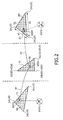
- Figure 2 illustrates a first embodiment of the mapping method in accordance with the invention.
- An input triangle T1 having vertices (u0,v0), (u1,v1) and (u2,v2) is linked to the intermediate rectangle triangle T0 via an inverse affine transform BT that can be expressed by the backward mapping equations (1).
- an output triangle T2 having vertices (x0,y0), (x1,y1) and (x2,y2) is linked to the intermediate rectangle triangle T0 via an inverse affine transform FT that can be expressed by the forward mapping equations (2).
- the mapping method in accordance with the invention is adapted to determine, for an intermediate point p0(n) of the intermediate rectangle triangle T0, n being an integer, an input transformed point p1(n) in the input triangle T1 using the inverse affine transform BT.
- the input transformed point p1(n) belonging to the input triangle is in general not located on a grid of texels with integer coordinates.
- a filtered intensity value I(n) corresponding to said point p1(n) is then derived according to a step of filtering a set of texels of the input triangles surrounding said input transformed point p1(n).
- the filtering step is based on the use of a bilinear filter adapted to implement a bilinear interpolation.
- Said bilinear interpolation is illustrated by the zoom in Figure 2 and is based, for example, on the use of the texture values I(t1) to I(t4) of the 4 texels t1 to t4 surrounding the input transformed point p1(n) and on the distance a 1 to a4 of said point p1(n) with respect to said 4 texels.
- the filtering step is based on the use of two mono-dimensional finite impulse response FIR filters applied sequentially in a horizontal direction and in a vertical direction.
- the filter taps are determined on the basis of the impulse response IR1 or IR2 which is centered on the input transformed point p1(n) according to a given direction, i.e. horizontal or vertical, and of the grid GR of texels with integer coordinates, as illustrated in Figure 3 in the case of a four taps filter. This results in four coefficients h1 to h4 and v1 to v4 for each FIR filter.
- the horizontal FIR filter is applied to the four horizontal segments of the set of 16 texels, resulting in 4 intermediate filtered intensity values.
- the vertical FIR filter is applied to the 4 intermediate filtered intensity values, resulting in a final filtered intensity value I(n).
- the number of filter taps is not limited to 4 and that said number may be increased or decreased.
- Other filters can also be applied, such a polyphase filter for example, depending on the desired visual quality and/or the available computing power.
- the mapping method in accordance with the invention is adapted to determine, for said intermediate point p0(n), an output transformed point p2(n) in the output triangle T2 to which the filtered intensity value is then associated, using the direct affine transform FT.
- the mapping method in accordance with the invention then comprises a step of calculating a contribution to a set of pixels surrounding said output transformed point p2(n) on the basis of the filtered intensity value I(n) and of a location of the output point with respect to said set of pixels.
- Said calculating step can also include a sub-step of weighting the contribution j;(n) by a surface S2 corresponding to the direct affine transform FT of the unitary surface S0 associated with the intermediate point p0(n).
- the contributions can come from different output transformed points. Said contributions are added for said given pixel until the sum of the coefficients k i is equal to 1.
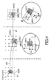
- Figure 4 illustrates another embodiment of the mapping method in accordance with the invention.
- the mapping method comprises a step of determining a first set of coefficients which defines the inverse affine transform BT, said inverse transform being capable of transforming an intermediate rectangle triangle into an input triangle.
- Said mapping method also comprises a step of determining a second set of affine coefficients corresponding to the direct affine transform FT, said direct transform being adapted to transform the intermediate rectangle triangle into an output triangle.
- the mapping method in accordance with said another embodiment is adapted to determine, for an intermediate point p0(n) of the intermediate rectangle triangle T0, an output transformed point p2(n) in the output triangle using the direct affine transform FT.
- Said transform is also adapted to transform a surface S0(n) formed by intermediate points into a surface S2(n). Then a pixel pix(n) with integer coordinates in the (x,y) coordinate system belonging to the surface S2(n), if any, is determined.
- the output vector V2(p,q) corresponding to the translation of the output transformed point p2(n) towards the translated pixel pix(n) is thus computed.
- a translation of the intermediate point p0(n) towards a translated intermediate point p'0(n) according to the intermediate vector V0 is then performed.
- the mapping method in accordance with the invention is then adapted to determine, for said translated intermediate point p'0(n), an input transformed point p'1(n) in the input triangle using the inverse affine transform BT (see continuous arrow in Figure 4).
- a filtered intensity value I(n) corresponding to said point p'1(n) is then derived from a step of filtering a set of texels of the input triangle surrounding said input transformed point p'1(n), as described before.
- Said another embodiment only requires a filtering step compared to the first embodiment and thus saves computing resources.
- the translated intermediate point p'0(n) is not computed.
- the mapping method is adapted to determine, for the intermediate point p0(n), an input transformed point p1(n) in the input triangle using the inverse affine transform BT (see continuous arrow in Figure 4).
- a translated input transformed point p'1(n) is then determined using the input vector V 1 (p",q") and a filtered intensity value I(n) corresponding to said point p'1 (n) is then derived from a step of filtering a set of texels of the input triangle surrounding said point p'1(n), as described before.
- mapping method in accordance with the invention creates an intermediate scan-conversion space and is adapted:
- Said mapping method can be refined according to different embodiments.
- the intermediate rectangle triangle is defined by lengths a and b, which are the lengths of the edges aligned with the s and t axis, i.e. opposite to the hypotenuse. These two lengths a and b are preferably chosen as a power of 2 in order to simplify the affine coefficients computing.
- the vectors based on affine coefficients ⁇ x ⁇ s ⁇ ⁇ x ⁇ t and ⁇ y ⁇ s ⁇ ⁇ y ⁇ t and are also preferably chosen as having a length lower than 1.
- the two lengths a and b equal to a power of 2 greater than the length of the corresponding edges e1 and e2 in the output triangle.
- Figure 5 illustrates such a bad case for the computation power requested for scan-conversion.
- the area of the intermediate triangle is much larger than the output triangle so that the number of scanned intermediate points is unbalanced compared with the actual number of pixels to be computed. That is why, according to another embodiment of the invention, the output triangle is cut into two sub-triangles. A new vertex is then introduced on the longest edge of the output triangle, as shown in Figure 6, for example at the basis of one of the triangle altitudes.
- the intermediate points (s0,t0), (s1,t1), (s2,t2) and (s3,t3) correspond to the output transformed points (x0,y0), (x1,y1 ), (x2,y2) and (x3,y3), respectively.
- the scan-conversion of the intermediate triangle is performed.
- an input transformed point in the input image is determined.
- the texels surrounding said input transformed point are subsequently filtered, as described before.
- the position of the output transformed point in the output triangle is also determined.
- the intermediate points are then re-sampled using an input-driven filter, as described before, said filter generating the intensity values of pixels positioned onto a grid with integer coordinates in the output image. Mapping a rectangle triangle to another one assures a well-balanced ratio between intermediate points and pixels.
- FIG. 7 shows a block diagram of a rendering device in accordance with the invention.
- Said rendering device is based on a hardware coprocessor realization.
- This coprocessor is assumed to be part of a shared memory system.
- the dynamic memory access DMA unit interfaces the coprocessor with a main memory (not represented).
- a controller CTRL controls the internal process scheduling.
- An input memory IM contains a local copy of the input image.
- An initialization INIT unit accesses geometric parameters, i.e. the vertices of the different triangles, through the DMA unit. From said geometric parameters, the INIT unit computes the affine coefficients and the edge slopes for the scan-conversion process.
- the rendering REND unit comprises a triangle scan TSC unit, which is adapted to compute, for each pixel p0 of a line of the intermediate triangle, the corresponding location p1 within the input image and the corresponding location p2 within the output image.
- the coordinates of the input point p 1 are subsequently used to address the input memory IM to get a set of texels with integer coordinates (u,v) to be filtered by a first filter INF unit, resulting in a filtered intensity value.
- Said filtered intensity value is provided together with the coordinates of the output point p2 to the inputs of a second filter OUTF unit, which is input driven.
- Said second filter unit is adapted to compute contributions to pixels of the output image having integer coordinates (x,y) and surrounding the output point p2.
- the output memory OM stores accumulated contributions. Once all the triangles have been rendered, the output memory is written back into a system memory, a video controller being adapted to access the output image in said system memory to display it.
- the mapping method in accordance with the invention can be implemented by means of items of hardware or software, or both.
- Said hardware or software items can be implemented in several manners, such as by means of wired electronic circuits or by means of an integrated circuit that is suitable programmed, respectively.
- the integrated circuit can be contained in a portable apparatus.
- the integrated circuit comprises a set of instructions.
- said set of instructions contained, for example, in a memory of the portable apparatus may cause the integrated circuit to carry out the different steps of the mapping method.
- the set of instructions may be loaded into the memory by reading a data carrier such as, for example, a disk.
- a service provider can also make the set of instructions available via a communication network such as, for example, the Internet.
Landscapes
- Engineering & Computer Science (AREA)
- Physics & Mathematics (AREA)
- Computer Graphics (AREA)
- General Physics & Mathematics (AREA)
- Theoretical Computer Science (AREA)
- Geometry (AREA)
- Image Generation (AREA)
- Image Processing (AREA)
- Manufacturing Optical Record Carriers (AREA)
- Indexing, Searching, Synchronizing, And The Amount Of Synchronization Travel Of Record Carriers (AREA)
Abstract
Description
- The present invention relates to a method of and a device for mapping an input image onto an output image.
- This invention may be used in digital apparatuses adapted to render graphical objects such as, for example, video decoders, 3D graphic accelerators, video game consoles, personal digital assistants or mobile phones.
- Texture mapping is a process for mapping an input image onto a surface of a graphical object to enhance the visual realism of a generated output image including said graphical object. Intricate detail at the surface of the graphical object is very difficult to model using polygons or other geometric primitives, and doing so can greatly increase the computational cost of said object. Texture mapping is a more efficient way to represent fine detail on the surface of the graphical object. In a texture mapping operation, a texture data item of the input image is mapped onto the surface of the graphical object as said object is rendered to create the output image.
- In conventional digital images, the input and output images are sampled at discrete points, usually on a grid of points with integer coordinates. The input image has its own coordinate space (u,v). Individual elements of the input image are referred to as "texels." Said texels are located at integer coordinates in the input coordinate system (u,v). Similarly, the output image has its own coordinate space (x,y). Individual elements of the output image are referred to as "pixels." Said pixels are located at integer coordinates in the output coordinate system (x,y).
- The process of texture mapping conventionally includes filtering texels from the input image so as to compute an intensity value for a pixel in the output image. Conventionally, the input image is linked to the output image via an inverse affine transform T-1 that can be expressed by the following equations:

where (u,v) are the coordinates of an input current point, (uref,vref) are the coordinates of an input reference point,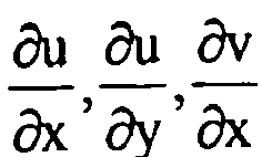

- Similarly, the output image is linked to the input image via a direct affine transform T that can be expressed by the following equations:

where (x,y) are the coordinates of an output current point, (xref,yref) are the coordinates of an output reference point,

- Equations (1) are called the backward mapping equations (i.e. the input coordinates are expressed as a function of the output coordinates) and equations (2) are called the forward mapping equations (i.e. the output coordinates are expressed as a function of the input coordinates).
- In the paper of Ghazanfarpour D., Peroche B., A high-quality filtering using forward texture mapping, Computers and Graphics, Pergamon Press Ltd. Oxford, GB, Vol. 15, No. 4, pp 569-577, January 1991, both techniques are mentioned.
- As explained above, the output image is made of a plurality of triangles defined by the positions of their vertices in both output and input coordinate systems. Said positions define a unique affine transform between a triangle in the input image and a triangle in the output image. To generate the output image, each output triangle is scan-converted to calculate the intensity value of each pixel of the triangle on the basis of intensity values of texels.
- The texels to be filtered for a given pixel are determined thanks to the inverse affine transform T-1. The result of the inverse affine transform of the given pixel is a transformed point in the input image. Texels neighboring said transformed point in the input image are then sampled, weighted and summed to compute the intensity value of the given pixel. This process is repeated for all the pixels in the output image.
- In order to make the scan-conversion relatively simple with only incremental computations, an expensive computational setup is required. This setup computes the affine coefficients


- A hardware system being able to compute these coefficients requires large arithmetic operators. This increases the silicon area needed for the implementation of said operators and thereafter the price of the hardware system.
- It is an object of the invention to propose a method of and a device for mapping an input image onto an output image, which is less computational expensive than the one of the
- To this end, the mapping method in accordance with the invention is characterized in that it comprises the steps of:
- determining an inverse affine transform for transforming an intermediate rectangle triangle into an input triangle;
- determining a direct affine transform for transforming the intermediate rectangle triangle into an output triangle;
- applying the inverse affine transform to intermediate points of the intermediate rectangle triangle so as to determine intermediate intensity values corresponding to said intermediate points on the basis of input intensity values of texels; and
- applying the direct affine transform to the intermediate points so as to determine output intensity values of pixels on the basis of the intermediate intensity values.
- As it will be explained in more detail hereinafter, the introduction of an intermediate space between the input image and the output image makes possible to determine easily the inverse affine transform and the direct affine transform, contrary to the prior art where the determination of the inverse or direct affine transform is more complex. As a consequence, the mapping method in accordance with the invention allows silicon area to be saved and less power to be consumed.
- The present invention also relates to a device implementing such a mapping method and to a portable apparatus comprising said device.
- Said invention finally relates to a computer program product comprising program instructions for implementing said mapping method.
- These and other aspects of the invention will be apparent from and will be elucidated with reference to the embodiments described hereinafter.
- The present invention will now be described in more detail, by way of example, with reference to the accompanying drawings, wherein:
- Figure 1 shows an image comprising triangle meshes;
- Figure 2 illustrates a first embodiment of the mapping method in accordance with the invention;
- Figure 3 shows a filtering step based on finite impulse response FIR filters;
- Figure 4 illustrates another embodiment of the mapping method in accordance with the invention;
- Figure 5 illustrates a particular case of transformation between an intermediate space and an output image;
- Figure 6 shows another embodiment of the mapping method in accordance with the invention to solve the particular case of Figure 5; and
- Figure 7 shows a block diagram of a rendering device in accordance with the invention.
- The present invention relates to a method of mapping texture data, i.e. luminance or chrominance data, of an input image split into input triangles onto an output image also split into corresponding output triangles. Input and output triangle meshes can be made of any possible triangle as shown in Figure 1.
- As neither output mesh nor input mesh can be regular for a backward mapping corresponding to equations (1) or a forward mapping corresponding to equations (2), respectively, an additional scan-conversion space (s,t), hereinafter referred to as intermediate space, is introduced. The current positions (x,y) and (u,v) in the output image and in the input image, respectively, are computed on the basis of a current point in said intermediate space.
- Figure 2 illustrates a first embodiment of the mapping method in accordance with the invention. The intermediate space comprises an intermediate rectangle triangle T0 having three vertices (s0,t0)=(0,0), (s1,t1)=(b,0) and (s2,t2)=(0,a). An input triangle T1 having vertices (u0,v0), (u1,v1) and (u2,v2) is linked to the intermediate rectangle triangle T0 via an inverse affine transform BT that can be expressed by the backward mapping equations (1). Thanks to the use of the intermediate rectangle triangle, the calculation of the affine coefficients


- Similarly, an output triangle T2 having vertices (x0,y0), (x1,y1) and (x2,y2) is linked to the intermediate rectangle triangle T0 via an inverse affine transform FT that can be expressed by the forward mapping equations (2). Thanks to the use of the rectangle triangle, the calculation of the affine coefficients


- As a consequence two sets of affine coefficients are computed:
- one for the backward mapping between the intermediate space and the input image, and
- one for the forward mapping between the intermediate space and the output image. These sets of coefficients are computed in a relatively computation-free setup, saving silicon area and consuming less power.
- Once the two sets of coefficients have been computed, the mapping method in accordance with the invention is adapted to determine, for an intermediate point p0(n) of the intermediate rectangle triangle T0, n being an integer, an input transformed point p1(n) in the input triangle T1 using the inverse affine transform BT. The input transformed point p1(n) belonging to the input triangle is in general not located on a grid of texels with integer coordinates. A filtered intensity value I(n) corresponding to said point p1(n) is then derived according to a step of filtering a set of texels of the input triangles surrounding said input transformed point p1(n).
- As a first example, the filtering step is based on the use of a bilinear filter adapted to implement a bilinear interpolation. Said bilinear interpolation is illustrated by the zoom in Figure 2 and is based, for example, on the use of the texture values I(t1) to I(t4) of the 4 texels t1 to t4 surrounding the input transformed point p1(n) and on the distance a 1 to a4 of said point p1(n) with respect to said 4 texels. The filtered intensity value I(n) is then derived as follows:

- As another example, the filtering step is based on the use of two mono-dimensional finite impulse response FIR filters applied sequentially in a horizontal direction and in a vertical direction. The filter taps are determined on the basis of the impulse response IR1 or IR2 which is centered on the input transformed point p1(n) according to a given direction, i.e. horizontal or vertical, and of the grid GR of texels with integer coordinates, as illustrated in Figure 3 in the case of a four taps filter. This results in four coefficients h1 to h4 and v1 to v4 for each FIR filter. The horizontal FIR filter is applied to the four horizontal segments of the set of 16 texels, resulting in 4 intermediate filtered intensity values. Then, the vertical FIR filter is applied to the 4 intermediate filtered intensity values, resulting in a final filtered intensity value I(n). It will be apparent to a person skilled in the art that the number of filter taps is not limited to 4 and that said number may be increased or decreased. Other filters can also be applied, such a polyphase filter for example, depending on the desired visual quality and/or the available computing power.
- Once the filtered intensity value I(n) associated with an intermediate point p0(n) of the intermediate rectangle triangle T0 has been determined, the mapping method in accordance with the invention is adapted to determine, for said intermediate point p0(n), an output transformed point p2(n) in the output triangle T2 to which the filtered intensity value is then associated, using the direct affine transform FT.
- The mapping method in accordance with the invention then comprises a step of calculating a contribution to a set of pixels surrounding said output transformed point p2(n) on the basis of the filtered intensity value I(n) and of a location of the output point with respect to said set of pixels.
- As a first example, the calculating step is based on the distance of the output transformed point p2(n) with respect to a set of pixels belonging to a grid of pixels with integer coordinates and surrounding said output transformed point. For example, if d1 to d4 are the distances between the output transformed point p2(n) and the 4 pixels surrounding said point p2(n), as shown in the zoom in Figure 2, the four contributions j1(n) to j4(n) are calculated as follows:

where D = d1 + d2 + d3 + d4 and where i = 1, 2, 3 or 4 - Said calculating step can also include a sub-step of weighting the contribution j;(n) by a surface S2 corresponding to the direct affine transform FT of the unitary surface S0 associated with the intermediate point p0(n). The contribution is then computed as follows:

- For a given pixel, the contributions can come from different output transformed points. Said contributions are added for said given pixel until the sum of the coefficients ki is equal to 1.
- Figure 4 illustrates another embodiment of the mapping method in accordance with the invention. The mapping method comprises a step of determining a first set of coefficients which defines the inverse affine transform BT, said inverse transform being capable of transforming an intermediate rectangle triangle into an input triangle. Said mapping method also comprises a step of determining a second set of affine coefficients corresponding to the direct affine transform FT, said direct transform being adapted to transform the intermediate rectangle triangle into an output triangle.
- Once the two sets of coefficients have been computed, the mapping method in accordance with said another embodiment is adapted to determine, for an intermediate point p0(n) of the intermediate rectangle triangle T0, an output transformed point p2(n) in the output triangle using the direct affine transform FT. Said transform is also adapted to transform a surface S0(n) formed by intermediate points into a surface S2(n). Then a pixel pix(n) with integer coordinates in the (x,y) coordinate system belonging to the surface S2(n), if any, is determined. The output vector V2(p,q) corresponding to the translation of the output transformed point p2(n) towards the translated pixel pix(n) is thus computed. The corresponding intermediate vector V0(p',q') in the intermediate space is thus derived as follows:

- A translation of the intermediate point p0(n) towards a translated intermediate point p'0(n) according to the intermediate vector V0 is then performed. The mapping method in accordance with the invention is then adapted to determine, for said translated intermediate point p'0(n), an input transformed point p'1(n) in the input triangle using the inverse affine transform BT (see continuous arrow in Figure 4). A filtered intensity value I(n) corresponding to said point p'1(n) is then derived from a step of filtering a set of texels of the input triangle surrounding said input transformed point p'1(n), as described before. Said another embodiment only requires a filtering step compared to the first embodiment and thus saves computing resources.
- Alternatively, the translated intermediate point p'0(n) is not computed. Instead, the mapping method is adapted to determine, for the intermediate point p0(n), an input transformed point p1(n) in the input triangle using the inverse affine transform BT (see continuous arrow in Figure 4). An input vector V1(p",q") corresponding to the intermediate vector V0(p',q') in the intermediate space is thus derived as follows:

- A translated input transformed point p'1(n) is then determined using the input vector V 1 (p",q") and a filtered intensity value I(n) corresponding to said point p'1 (n) is then derived from a step of filtering a set of texels of the input triangle surrounding said point p'1(n), as described before.
- The mapping method in accordance with the invention creates an intermediate scan-conversion space and is adapted:
- to perform a backward mapping from the intermediate space to the input image so as to determine intermediate intensity values corresponding to points of said intermediate space on the basis of input intensity values of texels of the input image, and
- to perform a forward mapping from the intermediate space to the output image so as to determine intensity values corresponding to pixels of said output image on the basis of the intermediate intensity values.
- Said mapping method can be refined according to different embodiments.
- According to a first embodiment of the invention, the intermediate rectangle triangle is defined by lengths a and b, which are the lengths of the edges aligned with the s and t axis, i.e. opposite to the hypotenuse. These two lengths a and b are preferably chosen as a power of 2 in order to simplify the affine coefficients computing.
- In order to assure no hole in the output image the vectors based on affine coefficients


- In some particular cases, there can be a great distortion between the intermediate rectangle triangle and the output triangle. Figure 5 illustrates such a bad case for the computation power requested for scan-conversion. The area of the intermediate triangle is much larger than the output triangle so that the number of scanned intermediate points is unbalanced compared with the actual number of pixels to be computed. That is why, according to another embodiment of the invention, the output triangle is cut into two sub-triangles. A new vertex is then introduced on the longest edge of the output triangle, as shown in Figure 6, for example at the basis of one of the triangle altitudes. In Figure 6, the intermediate points (s0,t0), (s1,t1), (s2,t2) and (s3,t3) correspond to the output transformed points (x0,y0), (x1,y1 ), (x2,y2) and (x3,y3), respectively. Then, the scan-conversion of the intermediate triangle is performed. For an intermediate point, an input transformed point in the input image is determined. The texels surrounding said input transformed point are subsequently filtered, as described before. The position of the output transformed point in the output triangle is also determined. The intermediate points are then re-sampled using an input-driven filter, as described before, said filter generating the intensity values of pixels positioned onto a grid with integer coordinates in the output image. Mapping a rectangle triangle to another one assures a well-balanced ratio between intermediate points and pixels.
- Figure 7 shows a block diagram of a rendering device in accordance with the invention. Said rendering device is based on a hardware coprocessor realization. This coprocessor is assumed to be part of a shared memory system. The dynamic memory access DMA unit interfaces the coprocessor with a main memory (not represented). A controller CTRL controls the internal process scheduling. An input memory IM contains a local copy of the input image. An initialization INIT unit accesses geometric parameters, i.e. the vertices of the different triangles, through the DMA unit. From said geometric parameters, the INIT unit computes the affine coefficients and the edge slopes for the scan-conversion process.
- These geometric parameters are then processed by the rendering REND unit, which is in charge of scan-converting the intermediate triangle setting-up during the initialization process by the INIT unit. The result of the scan-conversion process is stored in a local output memory OM.
- The rendering REND unit comprises a triangle scan TSC unit, which is adapted to compute, for each pixel p0 of a line of the intermediate triangle, the corresponding location p1 within the input image and the corresponding location p2 within the output image. The coordinates of the
input point p 1 are subsequently used to address the input memory IM to get a set of texels with integer coordinates (u,v) to be filtered by a first filter INF unit, resulting in a filtered intensity value. Said filtered intensity value is provided together with the coordinates of the output point p2 to the inputs of a second filter OUTF unit, which is input driven. Said second filter unit is adapted to compute contributions to pixels of the output image having integer coordinates (x,y) and surrounding the output point p2. The output memory OM stores accumulated contributions. Once all the triangles have been rendered, the output memory is written back into a system memory, a video controller being adapted to access the output image in said system memory to display it. - The mapping method in accordance with the invention can be implemented by means of items of hardware or software, or both. Said hardware or software items can be implemented in several manners, such as by means of wired electronic circuits or by means of an integrated circuit that is suitable programmed, respectively. The integrated circuit can be contained in a portable apparatus. The integrated circuit comprises a set of instructions. Thus, said set of instructions contained, for example, in a memory of the portable apparatus may cause the integrated circuit to carry out the different steps of the mapping method. The set of instructions may be loaded into the memory by reading a data carrier such as, for example, a disk. A service provider can also make the set of instructions available via a communication network such as, for example, the Internet.
- Any reference sign in the following claims should not be construed as limiting the claim. It will be obvious that the use of the verb "to comprise" and its conjugations do not exclude the presence of any other steps or elements besides those defined in any claim. The word "a" or "an" preceding an element or step does not exclude the presence of a plurality of such elements or steps.
Claims (11)
- A method of mapping an input image split into input triangles including texels onto an output image also split into corresponding output triangles including pixels, said method comprising the steps of:- determining an inverse affine transform (BT) for transforming an intermediate rectangle triangle (T0) into an input triangle (T1);- determining a direct affine transform (FT) for transforming the intermediate rectangle triangle (T0) into an output triangle (T2);- applying the inverse affine transform to intermediate points of the intermediate rectangle triangle (T0) so as to determine intermediate intensity values corresponding to said intermediate points on the basis of input intensity values of texels; and- applying the direct affine transform to the intermediate points so as to determine output intensity values of pixels on the basis of the intermediate intensity values.
- A method as claimed in claim 1, wherein the step of applying the inverse affine transform is adapted to transform an intermediate point (p0(n)) into an input transformed point (p1(n)) in the input triangle, and to determine, for said intermediate point, an intermediate intensity value based on a filtering operation of texels surrounding the input transformed point.
- A method as claimed in claim 2, wherein the filtering operation comprises a bilinear interpolation using four texels surrounding the input transformed point.
- A method as claimed in claim 2, wherein the filtering operation comprises applying sequentially a first mono-dimensional finite impulse response filter in a horizontal direction and a second mono-dimensional finite impulse response filter in a vertical direction.
- A method as claimed in claim 1, wherein the step of applying the direct affine transform is adapted to transform an intermediate point (p0(n)) into an output transformed point (p2(n)) in the output triangle, and to determine, for said intermediate point, a contribution to output intensity values of pixels surrounding said output transformed point on the basis of the intermediate intensity value.
- A method as claimed in claim 1, further comprising a step of determining lengths (a,b) of the intermediate rectangle triangle opposite to the hypotenuse which are equal to a power of 2 greater than the length of corresponding edges (e1,e2) in the output triangle.
- A method as claimed in claim 1, further comprising a step of dividing the output triangle into two sub-triangles before the step of applying the direct affine transform.
- A method as claimed in claim 1, wherein:- the step of applying the direct affine transform is adapted to determine an output point (p2(n)) and a corresponding output surface (S2(n)) in the output triangle (T2) from an intermediate point (p0(n)) and a corresponding intermediate unitary surface (S0(n)), to determine a pixel (pix(n)) with integer coordinates belonging to the output surface, and to determine an output vector (V2) defined by the output point and the pixel with integer coordinates; and- the step of applying the inverse affine transform is adapted to determine an input transformed point (p'1(n)) in the input triangle (T1) from the intermediate point and the output vector, and to filter the input intensity values of texels surrounding said input transformed point so as to derive an output intensity value of the pixel with integer coordinates.
- A device for rendering an output image split into corresponding output triangles including pixels on the basis of textured data of an input image split into input triangles including texels, said device comprising:- means (INIT) for determining an inverse affine transform (BT) for transforming an intermediate rectangle triangle into an input triangle, and for determining a direct affine transform (FT) for transforming an intermediate rectangle triangle into an output triangle;- means (TSC,IM,INF) for applying the inverse affine transform to intermediate points of the intermediate rectangle triangle (T0) so as to determine intermediate intensity values corresponding to said predetermined points on the basis of input intensity values of texels; and- means (TSC,OM,OUTF) for applying the direct affine transform to the intermediate points so as to determine output intensity values of pixels on the basis of the intermediate intensity values.
- A portable apparatus comprising a device as claimed in claim 9.
- A computer program product comprising program instructions for implementing, when said program is executed by a processor, a method as claimed in claim 1.
Priority Applications (1)
| Application Number | Priority Date | Filing Date | Title |
|---|---|---|---|
| EP04806496A EP1704535B1 (en) | 2004-01-06 | 2004-12-29 | Method of rendering graphical objects |
Applications Claiming Priority (3)
| Application Number | Priority Date | Filing Date | Title |
|---|---|---|---|
| EP04300010 | 2004-01-06 | ||
| PCT/IB2004/004332 WO2005076224A1 (en) | 2004-01-06 | 2004-12-29 | Method of rendering graphical objects |
| EP04806496A EP1704535B1 (en) | 2004-01-06 | 2004-12-29 | Method of rendering graphical objects |
Publications (2)
| Publication Number | Publication Date |
|---|---|
| EP1704535A1 EP1704535A1 (en) | 2006-09-27 |
| EP1704535B1 true EP1704535B1 (en) | 2007-10-24 |
Family
ID=34833802
Family Applications (1)
| Application Number | Title | Priority Date | Filing Date |
|---|---|---|---|
| EP04806496A Expired - Lifetime EP1704535B1 (en) | 2004-01-06 | 2004-12-29 | Method of rendering graphical objects |
Country Status (8)
| Country | Link |
|---|---|
| US (1) | US20070080963A1 (en) |
| EP (1) | EP1704535B1 (en) |
| JP (1) | JP2007518162A (en) |
| KR (1) | KR101107114B1 (en) |
| CN (1) | CN100476879C (en) |
| AT (1) | ATE376699T1 (en) |
| DE (1) | DE602004009714T2 (en) |
| WO (1) | WO2005076224A1 (en) |
Families Citing this family (12)
| Publication number | Priority date | Publication date | Assignee | Title |
|---|---|---|---|---|
| KR100860673B1 (en) * | 2007-03-13 | 2008-09-26 | 삼성전자주식회사 | Image generating apparatus and method for generating 3D images |
| US9019275B2 (en) | 2010-10-01 | 2015-04-28 | Lucid Software, Inc. | Manipulating graphical objects |
| US9293117B2 (en) | 2010-10-01 | 2016-03-22 | Lucid Software, Inc | Manipulating graphical objects |
| AU2013299742B2 (en) * | 2012-08-07 | 2016-08-04 | Lucid Software, Inc. | Manipulating graphical objects |
| CN107924579A (en) * | 2015-08-14 | 2018-04-17 | 麦特尔有限公司 | The method for generating personalization 3D head models or 3D body models |
| US10803272B1 (en) * | 2016-09-26 | 2020-10-13 | Digimarc Corporation | Detection of encoded signals and icons |
| US10853903B1 (en) | 2016-09-26 | 2020-12-01 | Digimarc Corporation | Detection of encoded signals and icons |
| US11257198B1 (en) | 2017-04-28 | 2022-02-22 | Digimarc Corporation | Detection of encoded signals and icons |
| CN109491781A (en) * | 2018-11-26 | 2019-03-19 | 深圳市瑞云科技有限公司 | A kind of cloud rendering method based on object unit |
| EP3667623A1 (en) * | 2018-12-12 | 2020-06-17 | Twikit NV | A system for optimizing a 3d mesh |
| CN116597109B (en) * | 2023-01-13 | 2023-12-22 | 东莘电磁科技(成都)有限公司 | A conformal mesh generation method for complex three-dimensional surfaces |
| CN118313333B (en) * | 2024-04-09 | 2025-08-26 | 北京华大九天科技股份有限公司 | A method and electronic device for repairing non-45° bevel edges in an integrated circuit physical layout to 45° bevel edges based on integer constraints |
Family Cites Families (19)
| Publication number | Priority date | Publication date | Assignee | Title |
|---|---|---|---|---|
| JP3313221B2 (en) * | 1993-12-28 | 2002-08-12 | 松下電器産業株式会社 | Image generation method and image generation device |
| US6064393A (en) * | 1995-08-04 | 2000-05-16 | Microsoft Corporation | Method for measuring the fidelity of warped image layer approximations in a real-time graphics rendering pipeline |
| JPH09106453A (en) * | 1995-10-11 | 1997-04-22 | Dainippon Screen Mfg Co Ltd | Image transformation method |
| US5808623A (en) * | 1996-10-07 | 1998-09-15 | Adobe Systems Incorporated | System and method for perspective transform in computer using multi-pass algorithm |
| US5999656A (en) * | 1997-01-17 | 1999-12-07 | Ricoh Co., Ltd. | Overlapped reversible transforms for unified lossless/lossy compression |
| US5905500A (en) * | 1997-02-19 | 1999-05-18 | Seiko Epson Corporation | Method and apparatus for adaptive nonlinear projective rendering |
| GB9716251D0 (en) * | 1997-08-01 | 1997-10-08 | Philips Electronics Nv | Attribute interpolation in 3d graphics |
| US6009190A (en) * | 1997-08-01 | 1999-12-28 | Microsoft Corporation | Texture map construction method and apparatus for displaying panoramic image mosaics |
| JP4056118B2 (en) * | 1997-12-26 | 2008-03-05 | 株式会社日立製作所 | Image processing device |
| FR2794269B1 (en) * | 1999-05-26 | 2001-08-17 | France Telecom | IMAGE CODING METHOD, WITH TRIANGULAR PARTITION AND REVERSIBLE TRANSFORMATION, AND CORRESPONDING DECODING METHOD |
| JP2000348213A (en) * | 1999-06-07 | 2000-12-15 | Sanyo Electric Co Ltd | Three-dimensional image generation device, three-dimensional image generation and display device, method therefor, and recording medium |
| US6683615B1 (en) * | 1999-06-09 | 2004-01-27 | 3Dlabs Inc., Ltd. | Doubly-virtualized texture memory |
| US6339428B1 (en) * | 1999-07-16 | 2002-01-15 | Ati International Srl | Method and apparatus for compressed texture caching in a video graphics system |
| US6542154B1 (en) * | 1999-08-07 | 2003-04-01 | Hewlett-Packard Company | Architectural extensions to 3D texturing units for accelerated volume rendering |
| US6731303B1 (en) * | 2000-06-15 | 2004-05-04 | International Business Machines Corporation | Hardware perspective correction of pixel coordinates and texture coordinates |
| FR2820255A1 (en) * | 2001-01-26 | 2002-08-02 | France Telecom | METHODS FOR ENCODING AND DECODING IMAGES, DEVICES, SYSTEMS, SIGNALS AND APPLICATIONS THEREOF |
| US20020126133A1 (en) * | 2001-02-08 | 2002-09-12 | 3Dlabs Inc., Ltd. | Fast anisotropic/anisotropy sensitive single MIPmap sampled filtering |
| US7106323B2 (en) * | 2001-02-08 | 2006-09-12 | 3Dlabs, Ltd | Rasterizer edge function optimizations |
| AU2003238511A1 (en) * | 2002-02-01 | 2003-09-02 | Koninklijke Philips Electronics N.V. | Stepless 3d texture mapping in computer graphics |
-
2004
- 2004-12-29 JP JP2006546405A patent/JP2007518162A/en active Pending
- 2004-12-29 EP EP04806496A patent/EP1704535B1/en not_active Expired - Lifetime
- 2004-12-29 AT AT04806496T patent/ATE376699T1/en not_active IP Right Cessation
- 2004-12-29 US US10/585,062 patent/US20070080963A1/en not_active Abandoned
- 2004-12-29 DE DE602004009714T patent/DE602004009714T2/en not_active Expired - Lifetime
- 2004-12-29 KR KR1020067013532A patent/KR101107114B1/en not_active Expired - Fee Related
- 2004-12-29 CN CNB2004800399016A patent/CN100476879C/en not_active Expired - Fee Related
- 2004-12-29 WO PCT/IB2004/004332 patent/WO2005076224A1/en not_active Ceased
Also Published As
| Publication number | Publication date |
|---|---|
| EP1704535A1 (en) | 2006-09-27 |
| CN1902661A (en) | 2007-01-24 |
| ATE376699T1 (en) | 2007-11-15 |
| WO2005076224A1 (en) | 2005-08-18 |
| JP2007518162A (en) | 2007-07-05 |
| KR20060124673A (en) | 2006-12-05 |
| US20070080963A1 (en) | 2007-04-12 |
| CN100476879C (en) | 2009-04-08 |
| DE602004009714T2 (en) | 2008-03-06 |
| KR101107114B1 (en) | 2012-01-30 |
| DE602004009714D1 (en) | 2007-12-06 |
Similar Documents
| Publication | Publication Date | Title |
|---|---|---|
| KR100261076B1 (en) | Rendering Method and Apparatus Performing Bump Mapping and Phong Shading Simultaneously | |
| US7277096B2 (en) | Method and apparatus for surface approximation without cracks | |
| US8289323B2 (en) | Drawing processing apparatus, texture processing apparatus, and tessellation method | |
| US8441497B1 (en) | Interpolation of vertex attributes in a graphics processor | |
| JP5232358B2 (en) | Rendering outline fonts | |
| CN108230435B (en) | Graphics processing using cube map textures | |
| JPH04222074A (en) | Inclination computing method for texture map | |
| US20060038823A1 (en) | System and method for upscaling low-resolution images | |
| US6184893B1 (en) | Method and system for filtering texture map data for improved image quality in a graphics computer system | |
| US5953015A (en) | Determining the level of detail for texture mapping in computer graphics | |
| US5109481A (en) | Quadratic interpolation for shaded image generation | |
| US20070080963A1 (en) | Method of rendering graphical objects | |
| JP2006517705A (en) | Computer graphics system and computer graphic image rendering method | |
| US5844567A (en) | Computer graphics system and method for texture mapping using triangular interpolation | |
| US5892516A (en) | Perspective texture mapping circuit having pixel color interpolation mode and method thereof | |
| US20080024510A1 (en) | Texture engine, graphics processing unit and video processing method thereof | |
| Fussell et al. | A vlsi-oriented architecture for real-time raster display of shaded polygons | |
| US6850244B2 (en) | Apparatus and method for gradient mapping in a graphics processing system | |
| Koh et al. | Fast generation and surface structuring methods for terrain and other natural phenomena | |
| JPH11185052A (en) | Apparatus and method for calculating texture mapping coordinates of three-dimensional computer graphics | |
| KR100313846B1 (en) | Method and Apparatus for Calculating Detail (LOD) in Bilinear Mip Mapping | |
| US20260057597A1 (en) | Generation of texture data based on pairs of multi-view digital images | |
| KR0153664B1 (en) | 3d object generator in a graphic system | |
| US7768512B1 (en) | System and method for rasterizing primitives using direct interpolation | |
| JPH11306381A (en) | Graphic operation device and method |
Legal Events
| Date | Code | Title | Description |
|---|---|---|---|
| PUAI | Public reference made under article 153(3) epc to a published international application that has entered the european phase |
Free format text: ORIGINAL CODE: 0009012 |
|
| 17P | Request for examination filed |
Effective date: 20060807 |
|
| AK | Designated contracting states |
Kind code of ref document: A1 Designated state(s): AT BE BG CH CY CZ DE DK EE ES FI FR GB GR HU IE IS IT LI LT LU MC NL PL PT RO SE SI SK TR |
|
| DAX | Request for extension of the european patent (deleted) | ||
| GRAP | Despatch of communication of intention to grant a patent |
Free format text: ORIGINAL CODE: EPIDOSNIGR1 |
|
| RAP1 | Party data changed (applicant data changed or rights of an application transferred) |
Owner name: NXP B.V. |
|
| GRAS | Grant fee paid |
Free format text: ORIGINAL CODE: EPIDOSNIGR3 |
|
| GRAA | (expected) grant |
Free format text: ORIGINAL CODE: 0009210 |
|
| AK | Designated contracting states |
Kind code of ref document: B1 Designated state(s): AT BE BG CH CY CZ DE DK EE ES FI FR GB GR HU IE IS IT LI LT LU MC NL PL PT RO SE SI SK TR |
|
| REG | Reference to a national code |
Ref country code: GB Ref legal event code: FG4D |
|
| REG | Reference to a national code |
Ref country code: CH Ref legal event code: EP |
|
| REG | Reference to a national code |
Ref country code: IE Ref legal event code: FG4D |
|
| REF | Corresponds to: |
Ref document number: 602004009714 Country of ref document: DE Date of ref document: 20071206 Kind code of ref document: P |
|
| NLV1 | Nl: lapsed or annulled due to failure to fulfill the requirements of art. 29p and 29m of the patents act | ||
| PG25 | Lapsed in a contracting state [announced via postgrant information from national office to epo] |
Ref country code: SE Free format text: LAPSE BECAUSE OF FAILURE TO SUBMIT A TRANSLATION OF THE DESCRIPTION OR TO PAY THE FEE WITHIN THE PRESCRIBED TIME-LIMIT Effective date: 20080124 Ref country code: NL Free format text: LAPSE BECAUSE OF FAILURE TO SUBMIT A TRANSLATION OF THE DESCRIPTION OR TO PAY THE FEE WITHIN THE PRESCRIBED TIME-LIMIT Effective date: 20071024 Ref country code: CH Free format text: LAPSE BECAUSE OF FAILURE TO SUBMIT A TRANSLATION OF THE DESCRIPTION OR TO PAY THE FEE WITHIN THE PRESCRIBED TIME-LIMIT Effective date: 20071024 Ref country code: ES Free format text: LAPSE BECAUSE OF FAILURE TO SUBMIT A TRANSLATION OF THE DESCRIPTION OR TO PAY THE FEE WITHIN THE PRESCRIBED TIME-LIMIT Effective date: 20080204 Ref country code: LI Free format text: LAPSE BECAUSE OF FAILURE TO SUBMIT A TRANSLATION OF THE DESCRIPTION OR TO PAY THE FEE WITHIN THE PRESCRIBED TIME-LIMIT Effective date: 20071024 |
|
| REG | Reference to a national code |
Ref country code: CH Ref legal event code: PL |
|
| PG25 | Lapsed in a contracting state [announced via postgrant information from national office to epo] |
Ref country code: LT Free format text: LAPSE BECAUSE OF FAILURE TO SUBMIT A TRANSLATION OF THE DESCRIPTION OR TO PAY THE FEE WITHIN THE PRESCRIBED TIME-LIMIT Effective date: 20071024 Ref country code: BG Free format text: LAPSE BECAUSE OF FAILURE TO SUBMIT A TRANSLATION OF THE DESCRIPTION OR TO PAY THE FEE WITHIN THE PRESCRIBED TIME-LIMIT Effective date: 20080124 Ref country code: PL Free format text: LAPSE BECAUSE OF FAILURE TO SUBMIT A TRANSLATION OF THE DESCRIPTION OR TO PAY THE FEE WITHIN THE PRESCRIBED TIME-LIMIT Effective date: 20071024 Ref country code: PT Free format text: LAPSE BECAUSE OF FAILURE TO SUBMIT A TRANSLATION OF THE DESCRIPTION OR TO PAY THE FEE WITHIN THE PRESCRIBED TIME-LIMIT Effective date: 20080324 Ref country code: IS Free format text: LAPSE BECAUSE OF FAILURE TO SUBMIT A TRANSLATION OF THE DESCRIPTION OR TO PAY THE FEE WITHIN THE PRESCRIBED TIME-LIMIT Effective date: 20080224 Ref country code: SI Free format text: LAPSE BECAUSE OF FAILURE TO SUBMIT A TRANSLATION OF THE DESCRIPTION OR TO PAY THE FEE WITHIN THE PRESCRIBED TIME-LIMIT Effective date: 20071024 |
|
| PG25 | Lapsed in a contracting state [announced via postgrant information from national office to epo] |
Ref country code: AT Free format text: LAPSE BECAUSE OF FAILURE TO SUBMIT A TRANSLATION OF THE DESCRIPTION OR TO PAY THE FEE WITHIN THE PRESCRIBED TIME-LIMIT Effective date: 20071024 |
|
| ET | Fr: translation filed | ||
| PG25 | Lapsed in a contracting state [announced via postgrant information from national office to epo] |
Ref country code: CZ Free format text: LAPSE BECAUSE OF FAILURE TO SUBMIT A TRANSLATION OF THE DESCRIPTION OR TO PAY THE FEE WITHIN THE PRESCRIBED TIME-LIMIT Effective date: 20071024 Ref country code: MC Free format text: LAPSE BECAUSE OF NON-PAYMENT OF DUE FEES Effective date: 20071231 Ref country code: DK Free format text: LAPSE BECAUSE OF FAILURE TO SUBMIT A TRANSLATION OF THE DESCRIPTION OR TO PAY THE FEE WITHIN THE PRESCRIBED TIME-LIMIT Effective date: 20071024 |
|
| PG25 | Lapsed in a contracting state [announced via postgrant information from national office to epo] |
Ref country code: RO Free format text: LAPSE BECAUSE OF FAILURE TO SUBMIT A TRANSLATION OF THE DESCRIPTION OR TO PAY THE FEE WITHIN THE PRESCRIBED TIME-LIMIT Effective date: 20071024 Ref country code: BE Free format text: LAPSE BECAUSE OF FAILURE TO SUBMIT A TRANSLATION OF THE DESCRIPTION OR TO PAY THE FEE WITHIN THE PRESCRIBED TIME-LIMIT Effective date: 20071024 Ref country code: SK Free format text: LAPSE BECAUSE OF FAILURE TO SUBMIT A TRANSLATION OF THE DESCRIPTION OR TO PAY THE FEE WITHIN THE PRESCRIBED TIME-LIMIT Effective date: 20071024 |
|
| PLBE | No opposition filed within time limit |
Free format text: ORIGINAL CODE: 0009261 |
|
| STAA | Information on the status of an ep patent application or granted ep patent |
Free format text: STATUS: NO OPPOSITION FILED WITHIN TIME LIMIT |
|
| 26N | No opposition filed |
Effective date: 20080725 |
|
| PG25 | Lapsed in a contracting state [announced via postgrant information from national office to epo] |
Ref country code: IE Free format text: LAPSE BECAUSE OF NON-PAYMENT OF DUE FEES Effective date: 20071231 |
|
| PG25 | Lapsed in a contracting state [announced via postgrant information from national office to epo] |
Ref country code: GR Free format text: LAPSE BECAUSE OF FAILURE TO SUBMIT A TRANSLATION OF THE DESCRIPTION OR TO PAY THE FEE WITHIN THE PRESCRIBED TIME-LIMIT Effective date: 20080125 Ref country code: EE Free format text: LAPSE BECAUSE OF FAILURE TO SUBMIT A TRANSLATION OF THE DESCRIPTION OR TO PAY THE FEE WITHIN THE PRESCRIBED TIME-LIMIT Effective date: 20071024 |
|
| PG25 | Lapsed in a contracting state [announced via postgrant information from national office to epo] |
Ref country code: FI Free format text: LAPSE BECAUSE OF FAILURE TO SUBMIT A TRANSLATION OF THE DESCRIPTION OR TO PAY THE FEE WITHIN THE PRESCRIBED TIME-LIMIT Effective date: 20071024 |
|
| PG25 | Lapsed in a contracting state [announced via postgrant information from national office to epo] |
Ref country code: CY Free format text: LAPSE BECAUSE OF FAILURE TO SUBMIT A TRANSLATION OF THE DESCRIPTION OR TO PAY THE FEE WITHIN THE PRESCRIBED TIME-LIMIT Effective date: 20071024 |
|
| PG25 | Lapsed in a contracting state [announced via postgrant information from national office to epo] |
Ref country code: LU Free format text: LAPSE BECAUSE OF NON-PAYMENT OF DUE FEES Effective date: 20071229 |
|
| PG25 | Lapsed in a contracting state [announced via postgrant information from national office to epo] |
Ref country code: HU Free format text: LAPSE BECAUSE OF FAILURE TO SUBMIT A TRANSLATION OF THE DESCRIPTION OR TO PAY THE FEE WITHIN THE PRESCRIBED TIME-LIMIT Effective date: 20080425 Ref country code: TR Free format text: LAPSE BECAUSE OF FAILURE TO SUBMIT A TRANSLATION OF THE DESCRIPTION OR TO PAY THE FEE WITHIN THE PRESCRIBED TIME-LIMIT Effective date: 20071024 |
|
| PG25 | Lapsed in a contracting state [announced via postgrant information from national office to epo] |
Ref country code: IT Free format text: LAPSE BECAUSE OF NON-PAYMENT OF DUE FEES Effective date: 20071231 |
|
| REG | Reference to a national code |
Ref country code: DE Ref legal event code: R084 Ref document number: 602004009714 Country of ref document: DE Effective date: 20110426 |
|
| REG | Reference to a national code |
Ref country code: FR Ref legal event code: TP Owner name: TRIDENT MICROSYSTEMS (FAR EAST) LTD., KY Effective date: 20120418 |
|
| REG | Reference to a national code |
Ref country code: DE Ref legal event code: R082 Ref document number: 602004009714 Country of ref document: DE Representative=s name: EPPING HERMANN FISCHER, PATENTANWALTSGESELLSCH, DE |
|
| REG | Reference to a national code |
Ref country code: DE Ref legal event code: R082 Ref document number: 602004009714 Country of ref document: DE Representative=s name: EPPING HERMANN FISCHER, PATENTANWALTSGESELLSCH, DE Effective date: 20121023 Ref country code: DE Ref legal event code: R081 Ref document number: 602004009714 Country of ref document: DE Owner name: ENTROPIC COMMUNICATIONS, INC., US Free format text: FORMER OWNER: TRIDENT MICROSYSTEMS (FAR EAST) LTD., GRAND CAYMAN, KY Effective date: 20121023 Ref country code: DE Ref legal event code: R081 Ref document number: 602004009714 Country of ref document: DE Owner name: ENTROPIC COMMUNICATIONS, INC., SAN DIEGO, US Free format text: FORMER OWNER: TRIDENT MICROSYSTEMS (FAR EAST) LTD., GRAND CAYMAN, KY Effective date: 20121023 Ref country code: DE Ref legal event code: R082 Ref document number: 602004009714 Country of ref document: DE Representative=s name: EPPING HERMANN FISCHER PATENTANWALTSGESELLSCHA, DE Effective date: 20121023 |
|
| REG | Reference to a national code |
Ref country code: FR Ref legal event code: TP Owner name: ENTROPIC COMMUNICATIONS, INC., US Effective date: 20131119 |
|
| PGFP | Annual fee paid to national office [announced via postgrant information from national office to epo] |
Ref country code: GB Payment date: 20141229 Year of fee payment: 11 |
|
| PGFP | Annual fee paid to national office [announced via postgrant information from national office to epo] |
Ref country code: FR Payment date: 20141217 Year of fee payment: 11 |
|
| PGFP | Annual fee paid to national office [announced via postgrant information from national office to epo] |
Ref country code: DE Payment date: 20151229 Year of fee payment: 12 |
|
| GBPC | Gb: european patent ceased through non-payment of renewal fee |
Effective date: 20151229 |
|
| REG | Reference to a national code |
Ref country code: FR Ref legal event code: ST Effective date: 20160831 |
|
| PG25 | Lapsed in a contracting state [announced via postgrant information from national office to epo] |
Ref country code: GB Free format text: LAPSE BECAUSE OF NON-PAYMENT OF DUE FEES Effective date: 20151229 |
|
| PG25 | Lapsed in a contracting state [announced via postgrant information from national office to epo] |
Ref country code: FR Free format text: LAPSE BECAUSE OF NON-PAYMENT OF DUE FEES Effective date: 20151231 |
|
| REG | Reference to a national code |
Ref country code: DE Ref legal event code: R119 Ref document number: 602004009714 Country of ref document: DE |
|
| PG25 | Lapsed in a contracting state [announced via postgrant information from national office to epo] |
Ref country code: DE Free format text: LAPSE BECAUSE OF NON-PAYMENT OF DUE FEES Effective date: 20170701 |