EP1704306B1 - A method for reducing noise of a high power combustion engine - Google Patents
A method for reducing noise of a high power combustion engine Download PDFInfo
- Publication number
- EP1704306B1 EP1704306B1 EP04809071A EP04809071A EP1704306B1 EP 1704306 B1 EP1704306 B1 EP 1704306B1 EP 04809071 A EP04809071 A EP 04809071A EP 04809071 A EP04809071 A EP 04809071A EP 1704306 B1 EP1704306 B1 EP 1704306B1
- Authority
- EP
- European Patent Office
- Prior art keywords
- exhaust system
- sound
- attenuation
- effect
- combustion engine
- Prior art date
- Legal status (The legal status is an assumption and is not a legal conclusion. Google has not performed a legal analysis and makes no representation as to the accuracy of the status listed.)
- Expired - Lifetime
Links
Images


Classifications
-
- F—MECHANICAL ENGINEERING; LIGHTING; HEATING; WEAPONS; BLASTING
- F01—MACHINES OR ENGINES IN GENERAL; ENGINE PLANTS IN GENERAL; STEAM ENGINES
- F01N—GAS-FLOW SILENCERS OR EXHAUST APPARATUS FOR MACHINES OR ENGINES IN GENERAL; GAS-FLOW SILENCERS OR EXHAUST APPARATUS FOR INTERNAL-COMBUSTION ENGINES
- F01N13/00—Exhaust or silencing apparatus characterised by constructional features
- F01N13/02—Exhaust or silencing apparatus characterised by constructional features having two or more separate silencers in series
-
- F—MECHANICAL ENGINEERING; LIGHTING; HEATING; WEAPONS; BLASTING
- F01—MACHINES OR ENGINES IN GENERAL; ENGINE PLANTS IN GENERAL; STEAM ENGINES
- F01N—GAS-FLOW SILENCERS OR EXHAUST APPARATUS FOR MACHINES OR ENGINES IN GENERAL; GAS-FLOW SILENCERS OR EXHAUST APPARATUS FOR INTERNAL-COMBUSTION ENGINES
- F01N1/00—Silencing apparatus characterised by method of silencing
Definitions
- the invention relates to sound attenuation of noise at the release of exhaust gases from a high power combustion engine.
- a traditional method for providing a system of attenuators for sound attenuation comprises that such attenuators are built and supplied as one unit. Such a unit tends to become bulky.
- a traditional system for sound attenuation of noise relating to an exhaust system of exhaust gases at a ship involves the use of a standardized system of attenuators, which are wrapped in walls of metals.
- a standardized system of attenuators may as such be called an attenuator and is a bulky unit with a large cross section area corresponding to a typical diameter of 2-4 meters. This means that in the case of a cruise ship, typically equipped with six diesel engines, the sound attenuators consume valuable space, which otherwise could be used for additional cabins.
- a first type of reactive attenuator is a reflection attenuator, which comprises an increase of the cross-section area. This area increase gives rise to a reflection wave, which propagates in a direction opposite to the propagation of the sound.
- Such an obstacle may be regarded as a wall, in which the sound rebounds.
- a second type of reactive attenuator is a resonance attenuator, which influences the propagation of the sound in a channel.
- Such an obstacle functions as a pitfall, into which the progressing sound falls on its way towards the orifice.
- the sound-attenuation properties for a reactive attenuator are also dependent on where in the system the sound attenuator is placed.
- Attenuator is a resistive attenuator.
- a resistive attenuator is a round or square tube, the sides of which are coated with an absorbent or a porous medium of small coupled cavities.
- Such a sound attenuator intended for a ventilation system is described in the patent document GB 2,122,256 .
- Another resistive attenuator intended for exhaust system is described in US 2,826,261 .
- absorbent there is usually used mineral wool or glass wool included some adhesive, which causes the absorbent to have a bonded structure.
- a gas-permeable surface layer, such as a perforated plate, may also protect the absorbent.
- Such a resistive attenuator will have a sound-attenuating property, which covers a wide frequency range and is dependant, besides on the thickness and rate of flow of the absorbent, also on the length and the inner area of the attenuator.
- the ratio of the absorbent thickness to the length of the acoustic waves, which are part of the sound is determining for the attenuation of lower frequencies.
- a satisfactory attenuation is achieved for sound frequencies at which the thickness of the absorbent is larger than a quarter of a wavelength of the sound.
- the sound attenuation properties then decrease drastically for sound of lower frequencies, which has a greater wavelength.
- Attenuators as well as other type of attenuators may be combined into an element.
- An example of such an element is described in US 4,371,054 .
- WO 98/27321 shows an example of a system with a reflective and a reactive attenuator.
- a remaining problem is to efficiently supply attenuators for elongated exhaust channels.
- Methods for modeling noise in exhaust system may be based on four-pole theory, handling low frequencies, or based on power flow models, handling high frequencies. There is no known efficient method for modeling exhaust systems for large combustion engines with multiple attenuators and other components over the entire frequency range.
- Yet another problem is during design of the system to efficiently model and try different combinations of elements with varying characteristics, and get an immediate result on the effect on sound attenuation, such as on-board a ship, depending on the combination of elements.
- Another remaining problem is to arrange a sound attenuation system in a reliable manner, which not only meets noise requirements, but also insures that the sound attenuation system is not oversized nor overestimated from a design standpoint. Another problem is to during the design phase of a sound attenuation system also being able to minimize the pressure drop, since a large pressure drop reduces the efficiency of the combustion engine with or without a turbo charger.
- a particular problem is design and assembly of a noise reduction system intended for a cruise ship, where demands on noise levels are rigorous, due to high demand on passenger comfort.
- An object of the invention is to provide a method for supplying a system for sound attenuation of noise relating to an exhaust system of exhaust gases from a high power combustion engine, where elements intended for sound attenuation are, more efficiently and accurately than with known methods, modeled in a computing device, and the method does not have the above mentioned disadvantages.
- the method shall enable that an estimated noise level is calculated with high accuracy, not only in a band of low frequencies and in a band of high frequencies, but also in a band of intermediate frequencies. Hence, the method enables estimation of noise and attenuating effect in the whole frequency area.
- a system for sound attenuation according the invention shall enable the exhaust system to be supplied with attenuators which diameters are smaller compared with a traditional system for sound attenuation.
- a method according to the invention shall provide a system for sound attenuation where attenuator elements are placed along the exhaust system of exhaust gases, wherein such a system consumes less space and has less weight compared with exhaust system fitted with sound attenuators according to previously described traditional methods.
- Such a traditional method comprises the use of a bulky container of a system of attenuators.
- the method according to the invention shall enable a user to quickly perform analysis of different design alternatives. The method enable that requirements on noise levels in close vicinity of the outlet of the exhaust system is met. The method shall enable to meet such requirements in a frequency range 25 Hz to 10 kHz. Further, the method shall provide less pressure drop than traditional methods.
- each element comprises a first reactive part, a resistive part and a second reactive part.
- An alternative name to such an element is a triple or a triple attenuator.
- Another object of the invention is to provide a computer program capable of executing any of the steps according to the above-mentioned method.
- Yet another object of the invention is to provide an exhaust system with a sound reduction system supplied according to the above-mentioned method.
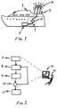
- Figure 1 shows an overview of a ship with an exhaust system and a position to which a desired noise level is associated.
- Figure 2 shows a simplified flow diagram of a method according to the invention, a computing device and a user, such as an engineer, of the device.
- Figure 3 shows an overview of an attenuator element, the characteristics of which are used in the modeling step of the method. That type of element is modeled at a plurality of positions in the exhaust system.
- Figure 4 shows an example of an exhaust system with sound attenuation according to the invention.
- Figure 5 is a schematic drawing of a display comprising entries to a number of functions, which relates to the invention.
- Figure 6 is an overview, which shows that a contribution to an attenuating effect of an attenuation element is achieved in a low frequency area, an intermediate frequency area and an upper frequency area.
- Figure 7 shows a simplified graph of a calculated attenuating effect of an attenuation element 20 in the low frequency area.
- Figure 8 shows a simplified graph of an attenuation effect in the low frequency area of a sound reduction system comprising attenuation elements supplied according to the invention.
- Figure 1 shows an example of an exhaust system 1 for exhaust gases from a high power combustion engine, such as a diesel engine 4 for a ship 2.
- a position 3 is associated to a desired noise level. Such a position 3 is typically in close vicinity to the outlet of the exhaust system.
- a desired noise level is typically defined as an A-weighted value. Desired values are typically in the range of 60 dBA - 70 dBA.
- the exhaust system comprises a number of different units. Examples of such units are a turbo charger, a boiler 5 or a heat exchanger 5.
- a heat exchanger is a common unit, in which part of the surplus heating of the hot gas is taken out for heating water or oil.
- the attenuators 20 are positioned after the boiler 5. In an alternative embodiment, attenuators may also be positioned before the heat exchanger or the boiler.
- Figure 2 shows a simplified flow diagram of a method according to the invention. Further, figure 2 indicates that the steps of adding elements 7, inserting individual attenuating devices 8 and the calculating step 9 is performed by means of a computing device 13. It should be understood that an embodiment the invention may also comprise the modeling of the non-attenuated exhaust system, including the orifice, straight pipes, curved pipes etc. As an alternative, modeling of the non-attenuated exhaust system may be performed in another computing environment, different from the computing device. Constraints and details of the non-attenuated system may be defined in blueprints or as CAD-drawings or similar.
- the adding step 7 of figure 2 involves the modeling of a plurality of attenuator elements 20 shown in figure 3.
- Such elements comprise a first reactive part 21, a resistive part 22 and a second reactive part 23.
- the inventors have found that the use of such elements in a real world exhaust system 1, based on the invention, results in increased accuracy between an estimated noise level and a measured noise level. It is beneficial to use two to four such elements.
- these elements are typically the first sound attenuators to be added to a model of a real world exhaust system. The position of such element in the channel is often dependent on available space between curved pipes.
- the adding step 7 typically involves an interaction between a user 14 and the computing device 13.
- the user 14 such as a design engineer, enters parameters relating to the elements through a user interface. Examples on such parameters relating to the element 20 are shown in figure 3 and may be D1, D2, xi smooth and xi perforation. Such sound damping characteristics is described in further detail in the description below of figure 3.
- the inserting step of figure 2 involves the insert of at least one individual attenuating device.
- a typical real world attenuated system such as for a cruise ship, based on the invention comprise at least four such individual devices.
- Such an individual device has its main damping effect in the low frequency area or in the upper frequency area.
- Such an individual device with damping in the low frequency area is of similar construction as part 21 or 23 of the attenuation element 20.
- Such an individual device with damping in the high frequency area is of similar construction as part 22 of the attenuation element 20.
- an individual device is either a reactive or a resistive device.
- additional individual attenuating devices may be added.
- acoustic characteristics of already added individual attenuating devices may be altered.
- the inserting step 8 may comprise that the position of already inserted elements or individual devices is altered.
- the change of position of reactive individual devices and elements has an impact on the total attenuation effect in the low frequency area.
- the attenuation effect in the high frequency area is dependent on the total length of resistive individual devices and the resistive parts 22 of the attenuation element. Further, the attenuation effect in the high frequency area is dependent on type of material r 0 , total amount of material, type of perforation x i and other parameters of the resistive parts shown in figure 3.
- the calculating step 9 comprises a calculation of an attenuating effect of the elements 20 and an attenuating effect of the single attenuating devices. It is beneficial to present the result of the calculation to the user of the computing device 13 as a total attenuating effect in a plurality of frequency bands.
- An aim is to make the attenuating effect at least equal to a needed attenuation in the real world exhaust system 1.
- the needed attenuation relates to the sound pressure level of the high power combustion engine.
- the needed attenuation may be calculated as the sound pressure level subtracted with the desired noise level.
- the calculating step 8 of figure 2 may comprise a calculation of an estimated noise level corresponding to a position in close vicinity of the outlet of the exhaust system.
- the calculation step 9 comprise that a contribution to an estimated attenuated effect comprise a band of frequencies corresponding to damping of intermediate frequencies related to an element 20.
- the damping is calculated by use of four-pole theory and by use of power flow models.
- the high power combustion engine 4 functions as a sound source to the exhaust system.
- the sound pressure level of the combustion engine is typically an anticipated sound pressure level and is supplied as input to the computing device as a sound spectrum of band of frequencies.
- the manufacturer of the engine typically supplies or defines the sound spectrum. It is of particular importance that the sound spectrum is reliable and corresponds to the sound spectrum of the real world engine to be supplied as sound source of the real world exhaust system. In a preferred embodiment that sound spectrum is based on sound power, which is independent of distance from the sound source.
- a traditional method for supplying the sound spectrum of the engine involves the measurement of noise outside the engine tail pipe by means of a microphone.
- Such a method further involves that the measured sound spectrum is transformed by calculation to a sound power spectrum corresponding to the sound power of the combustion engine.
- Another system parameter, which normally is kept constant, during the modeling and calculating step is the total length of exhaust channel.
- the total length, as well as other boundary conditions, is commonly indicated on blueprints or drawings.
- each element, individual attenuated device and other parts of the modeled exhaust system are modeled as software objects or similar.
- the steps handled by means of a computing device may be implemented in software executable in any type of computing environment.
- Figure 3 shows an overview of an attenuator element 20, the characteristics of which are used as parameters in the adding step 7 of the method.
- Figure 3 shows a cross section of such an attenuator element. That type of element is modeled at a plurality of positions in an exhaust system 47 according to Figure 4.
- Such an element comprises a first reactive part 21, a resistive part 22 and a second reactive part 23.
- Such an element may also be seen as an acoustic element, which suggests that the first reactive part 21, the resistive part 22 and the second reactive part 23 are not necessarily physically fitted together.
- the element is particular suitable due to the following.
- a sound field arises in the same way as in a room, which sound field is determined by the boundary conditions in the channel.
- the acoustic boundary conditions are thus determined by the properties of the limiting surfaces of the channel. Not least at the orifice are the acoustic boundary conditions complicated, since the very shape of the orifice, as well as the phenomenon that hot gas at a high pressure is thrown out into the air at normal temperature and normal atmospheric pressure, influence the sound generation. At the orifice, the progressing sound is subjected to strong reflection, whereby part of the sound energy passes in the opposite direction. The reflected sound gives rise to a sound field with standing waves in the channel. In an unattenuated channel system, the sound field is determined almost exclusively by these reflection waves.
- Figure 4 shows an example of an exhaust system with sound attenuation according to the invention.
- 20a and 20b are two attenuating elements each having two reactive parts.
- the reactive parts typically have tuned frequencies between 65 Hz to 200 Hz.
- the elements 20a and 20b make efficient use of available space and are cost effective to supply to the exhaust system.
- the exhaust system comprises an inlet 40, which is connected to a sound source such as a high power combustion engine 4. From an acoustic standpoint, the inlet 40 is considered an endless pipe.
- the exhaust system also comprises an outlet 46 or orifice, the shape and size of which have considerable influence on the sound in the channel. As the sound leaves the channel, it results in reflection waves.
- An exhaust system such as shown in figure 4, often comprises a boiler 42 or heat exchanger.
- Such a boiler 42 has three main effects on the acoustic environment.
- the first effect is that the boiler 42 reduces the temperature of the exhaust gas and hence the speed of sound is different before and after the boiler 42.
- the second effect is that the boiler 42 may be seen as a boundary condition, similar to the orifice.
- a boiler 42, or rather an area increase/decrease in the boiler introduces distinct impedance. This makes it suitable to place single reactive devices as well as reactive parts of the attenuating element in relation to the boiler 42. It is an advantage to use such a relation to place the opening of a single attenuating device, such as 43 and 45 in figure 4, at an odd number of a quarter of a wavelength from a distinct impedance.
- the third main effect of the boiler 42 is that it has an attenuating effect, which in an embodiment of the invention is taken in account.
- figure 4 is schematic and a real world exhaust system comprise other parts than indicated in the figure such as bend pipes, flanges, connections to multiple engines etc.
- Figure 5 is a schematic drawing of a display comprising entries to a number of functions 51-55 displayed by means of the computing device 13, which relates to the invention.
- the inventors have found that is an advantage to implement functions such as pre analysis 51, elements 52, system 53, source/termination 54 and post analysis 55.
- Such an elements function may comprise the definition of physical and acoustic characteristics of elements 20 as well as individual devices.
- Other examples of elements are a boiler, a heat exchanger, a pipe inlet, a pipe outlet or a flange.
- a system function may comprise that different elements are added or inserted to a model of an exhaust system 1. Many alternative definitions of functions are possible in an embodiment of the invention.
- Figure 6 is an overview, which shows that a contribution to an attenuating effect in the intermediate frequencies 60 is achieved by use of the attenuator element 20.
- an attenuating effect is calculated by use of band of frequencies. It is beneficial to use bands where each band corresponds to a tierce. Other distances between the bands are possible.
- Figure 6 shows that the attenuating effect of the element 20 in the low frequencies 61 is mainly achieved by the reactive parts 21 and 23.
- resistive part 22 contributes to the attenuating effect in the low frequency area as a reflective attenuator.
- the resistive part 22 works as a reflective attenuator in both the direction of mass flow of exhaust gases, as well as a reflective attenuator in the other direction of reflective waves from other elements or, for instance, reflective waves from the orifice.
- the inventors have found that it is beneficial to start with the resistive part 22 at the acoustic and physical design of a module.
- the speed of sound is 500 m/s which gives that for ⁇ /4 L3 should be approximately 1 m.
- Part 21 and 23 should be tuned such that 125 Hz is the center frequency or close to the center frequency of the complete element in the low frequency area. It is in this case beneficial to tune part 21 to a frequency close to 110 Hz and part 23 close to 140 Hz.
- the above-mentioned calculation ⁇ /4 in order to place the inlet of the pipes at pressure maximum gives that L2 of part 21 is 1.14 meters and L4 of part 23 is 0.89 meters.
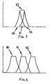
- Figure 7 shows a simplified graph of a calculated attenuating effect of an attenuation element 20 in the low frequency area.
- the center frequency 125 Hz corresponds to the centre 71 of the attenuation frequency band.
- the first reactive part 21 corresponds to the left 70 curve of an attenuation effect with a centre frequency close to 110 Hz.
- the second reactive part 22 corresponds to the right 72 curve of an attenuation effect with a centre frequency close to 125 Hz. It is beneficial to trim the acoustic performance of each attenuation element such that the total attenuation effect of the element, in the low frequency area, has flat top 73 corresponding to a certain damping measured in dB.
- Figure 8 shows a simplified graph of the attenuation effect in the low frequency area of a sound reduction system comprising attenuation elements supplied according to the invention.
- Each of the curves 80, 81 and 82 corresponds to an attenuation element 20.
- the attenuation effect of each element 20 may result in damping effects with different amplitudes measured in dB, this in contrast to the figure, which shows a system with attenuation elements 20 with similar amplitude 80, 81 and 82 for its band of frequencies.
- One important advantage of a method according to the invention is that it enables a user to adapt the total attenuation effect of each of the attenuation elements 80, 81 and 82 to the corresponding sound effect of the high power combustion engine 4.
- the elements and individual devices has a total attenuating effect greater than, if each attenuating effect would be added one by one to a total effect.
- the reason for that is that the elements and devices work together as a sound attenuation system.
- One acoustic effect that the invention makes use of is that one may introduce reflective waves by adding elements with resistive parts 21, that has a reflective character in the low frequency area, or individual resistive devices at suitable positions. Such suitable positions are odd numbers of 1/4 of desired wavelengths for attenuation.
- the attenuation elements 20a and 20b, as well as individual devices 43, 45, are positioned in a model during the adding 7 and inserting step 8 such that the total attenuation effect of the attenuation elements 80, 81 and 82 and the attenuation effect of individual devices match certain bands the frequency spectra of the corresponding sound effect of the high power combustion engine 4.
- a user 14 may try different combinations of individual devices and attenuation elements 20 during the repeating step 10 in order to achieve not only sufficient sound attenuation, but also to model the attenuation system such that it may be supplied to the exhaust system in a cost effective manner.
- the attenuating effect in the high frequency 62 area of each element is mainly achieved by the resistive part 22.
- the calculation of the attenuating effect is made such that an estimated attenuated effect comprises a band of frequencies corresponding to intermediate frequencies 60 of an element 20.
- Such a contribution to frequencies of an element 20 is calculated by use of four-pole theory and by use of power flow models.
- Each element 20 contributes to attenuation in the low frequencies, intermediate frequencies and high frequencies.
- the inventors have found that it is beneficial to use a cut-on frequency to determine at what frequency the calculation should be based on four-pole theory or power flow models.
- the cut-on frequency depends on the cross-section area of transport system and the speed of sound f o (A,c).
- the cut-on frequency is typically calculated as: f 0 ⁇ 1 , 84 * c ⁇ * d where c is the speed of sound and d the diameter of the transport system at the element.
- c is the speed of sound
- d the diameter of the transport system at the element.
- the cut-on frequency determines that it is only the contribution from four-pole theory that is used in the calculating step 9 to add to the calculated attenuated effect below the cut-on frequency for each of the attenuation elements 20. And similar, in the same possible embodiment, the cut-on frequency determines that only the contribution from power flow models is used in the calculating step 9 to add to the calculated attenuated effect above the cut-on frequency.
- the attenuating effect of a real world attenuating element is mainly coming from the resistive part 22. It should be noted that the attenuated effect in the high frequency area of the resistive part 22 is not depending on the position of the element. Nor is the acoustic effect of the single attenuating devices with resistive character depending on position. However, it is beneficial to place at least some resistive attenuating devices before a possible boiler 42 or heat exchanger.
Landscapes
- Engineering & Computer Science (AREA)
- Chemical & Material Sciences (AREA)
- Combustion & Propulsion (AREA)
- Mechanical Engineering (AREA)
- General Engineering & Computer Science (AREA)
- Exhaust Silencers (AREA)
- Cylinder Crankcases Of Internal Combustion Engines (AREA)
- Supercharger (AREA)
- Tires In General (AREA)
Abstract
Description
- The invention relates to sound attenuation of noise at the release of exhaust gases from a high power combustion engine.
- An important factor to consider, when desiging an exhaust system connected to one or several high power combustion engines, is the noise in close vicinity to the outlet of the system. Examples of such a high power combustion engine are a diesel engine for a ship, for a power plant or for a train. By high power combustion engine is meant an engine with a total effect of more than 500 kW. A traditional method for providing a system of attenuators for sound attenuation comprises that such attenuators are built and supplied as one unit. Such a unit tends to become bulky.
- A traditional system for sound attenuation of noise relating to an exhaust system of exhaust gases at a ship involves the use of a standardized system of attenuators, which are wrapped in walls of metals. Such a standardized system of attenuators may as such be called an attenuator and is a bulky unit with a large cross section area corresponding to a typical diameter of 2-4 meters. This means that in the case of a cruise ship, typically equipped with six diesel engines, the sound attenuators consume valuable space, which otherwise could be used for additional cabins.
- It is known that one may reduce noise from an exhaust system of a high power combustion engine by use of different types of damping techniques. One way of reducing the noise is to arrange obstacles or steps of acoustic impedance to the progressing acoustic wave in the exhaust system channel. In this way, one prevents noise from propagating in the channel of the exhaust system. Such a type of sound attenuator is commonly known as a reactive attenuator. Such a reactive attenuator consumes no energy. There are two main principles to which such reactive attenuators works. A first type of reactive attenuator is a reflection attenuator, which comprises an increase of the cross-section area. This area increase gives rise to a reflection wave, which propagates in a direction opposite to the propagation of the sound. Such an obstacle may be regarded as a wall, in which the sound rebounds. A second type of reactive attenuator is a resonance attenuator, which influences the propagation of the sound in a channel. Such an obstacle functions as a pitfall, into which the progressing sound falls on its way towards the orifice. The sound-attenuation properties for a reactive attenuator are also dependent on where in the system the sound attenuator is placed.
- Another type of attenuator is a resistive attenuator. One typical embodiment of a resistive attenuator is a round or square tube, the sides of which are coated with an absorbent or a porous medium of small coupled cavities. Such a sound attenuator intended for a ventilation system is described in the patent document
GB 2,122,256 US 2,826,261 . As absorbent, there is usually used mineral wool or glass wool included some adhesive, which causes the absorbent to have a bonded structure. A gas-permeable surface layer, such as a perforated plate, may also protect the absorbent. Such a resistive attenuator will have a sound-attenuating property, which covers a wide frequency range and is dependant, besides on the thickness and rate of flow of the absorbent, also on the length and the inner area of the attenuator. The ratio of the absorbent thickness to the length of the acoustic waves, which are part of the sound is determining for the attenuation of lower frequencies. A satisfactory attenuation is achieved for sound frequencies at which the thickness of the absorbent is larger than a quarter of a wavelength of the sound. The sound attenuation properties then decrease drastically for sound of lower frequencies, which has a greater wavelength. Even when the ratio of the wavelength to absorbent thickness is about 1/8, the absorption is only half as great, and theratio 1/16 it is only 20% of the absorption, which is obtained at theratio 1/4. Since a certain absorption capacity remains, in many cases a sufficient absorption may be obtained by increasing the length of the total absorbent in the exhaust system. In addition, the cross-section area or diameter of the exhaust system is of importance for the sound attenuation obtained since the reduction in the upper frequency range of the sound decreases with increased cross-section area. Hence, a problem with such a resistive attenuator is that the absorbing layer must be thick to be able to absorb low frequencies. This means large volume. However, a larger total length of the attenuator may compensate a smaller absorbent thickness. This leads to an increased cost of the sound attenuation obtained. Another problem for an exhaust system is that the pressure drop must be limited. This leads to a relatively large cross-section area of the system. The sound attenuation at the upper frequency range of the sound is thus reduced. It often appears that for traditional methods providing sound attenuation system properties, which are obtained in a laboratory, especially at low frequencies, are seldom obtained in practice. This leads to a great oversizing in order to insure sufficient sound attenuation. - The above-mentioned attenuators as well as other type of attenuators may be combined into an element. An example of such an element is described in
US 4,371,054 . -
WO 98/27321 - Methods for modeling noise in exhaust system may be based on four-pole theory, handling low frequencies, or based on power flow models, handling high frequencies. There is no known efficient method for modeling exhaust systems for large combustion engines with multiple attenuators and other components over the entire frequency range.
- Yet another problem is during design of the system to efficiently model and try different combinations of elements with varying characteristics, and get an immediate result on the effect on sound attenuation, such as on-board a ship, depending on the combination of elements.
- Another remaining problem is to arrange a sound attenuation system in a reliable manner, which not only meets noise requirements, but also insures that the sound attenuation system is not oversized nor overestimated from a design standpoint. Another problem is to during the design phase of a sound attenuation system also being able to minimize the pressure drop, since a large pressure drop reduces the efficiency of the combustion engine with or without a turbo charger.
- A particular problem is design and assembly of a noise reduction system intended for a cruise ship, where demands on noise levels are rigorous, due to high demand on passenger comfort.
- An object of the invention is to provide a method for supplying a system for sound attenuation of noise relating to an exhaust system of exhaust gases from a high power combustion engine, where elements intended for sound attenuation are, more efficiently and accurately than with known methods, modeled in a computing device, and the method does not have the above mentioned disadvantages. The method shall enable that an estimated noise level is calculated with high accuracy, not only in a band of low frequencies and in a band of high frequencies, but also in a band of intermediate frequencies. Hence, the method enables estimation of noise and attenuating effect in the whole frequency area. A system for sound attenuation according the invention shall enable the exhaust system to be supplied with attenuators which diameters are smaller compared with a traditional system for sound attenuation. A method according to the invention shall provide a system for sound attenuation where attenuator elements are placed along the exhaust system of exhaust gases, wherein such a system consumes less space and has less weight compared with exhaust system fitted with sound attenuators according to previously described traditional methods. Such a traditional method comprises the use of a bulky container of a system of attenuators. Further, the method according to the invention shall enable a user to quickly perform analysis of different design alternatives. The method enable that requirements on noise levels in close vicinity of the outlet of the exhaust system is met. The method shall enable to meet such requirements in a frequency range 25 Hz to 10 kHz. Further, the method shall provide less pressure drop than traditional methods.
- The above mentioned object is met by a method according to
claim 1. - The inventors have found that a particular suitable element to be used in the method, hence in the provided system for sound attenuation is an element where each element comprises a first reactive part, a resistive part and a second reactive part. An alternative name to such an element is a triple or a triple attenuator.
- Another object of the invention is to provide a computer program capable of executing any of the steps according to the above-mentioned method.
- Yet another object of the invention is to provide an exhaust system with a sound reduction system supplied according to the above-mentioned method.
- It should be understood that the figures and description of embodiments are merely examples of possible embodiments and should not limit the underlying inventive idea.
- The present invention will be described in more detail in connection with the enclosed schematic drawings.
- Figure 1 shows an overview of a ship with an exhaust system and a position to which a desired noise level is associated.
- Figure 2 shows a simplified flow diagram of a method according to the invention, a computing device and a user, such as an engineer, of the device.
- Figure 3 shows an overview of an attenuator element, the characteristics of which are used in the modeling step of the method. That type of element is modeled at a plurality of positions in the exhaust system.
- Figure 4 shows an example of an exhaust system with sound attenuation according to the invention.
- Figure 5 is a schematic drawing of a display comprising entries to a number of functions, which relates to the invention.
- Figure 6 is an overview, which shows that a contribution to an attenuating effect of an attenuation element is achieved in a low frequency area, an intermediate frequency area and an upper frequency area.
- Figure 7 shows a simplified graph of a calculated attenuating effect of an
attenuation element 20 in the low frequency area. - Figure 8 shows a simplified graph of an attenuation effect in the low frequency area of a sound reduction system comprising attenuation elements supplied according to the invention.
- Figure 1 shows an example of an
exhaust system 1 for exhaust gases from a high power combustion engine, such as adiesel engine 4 for aship 2. A position 3 is associated to a desired noise level. Such a position 3 is typically in close vicinity to the outlet of the exhaust system. A desired noise level is typically defined as an A-weighted value. Desired values are typically in the range of 60 dBA - 70 dBA. - As Figure 1 shows, the exhaust system comprises a number of different units. Examples of such units are a turbo charger, a boiler 5 or a heat exchanger 5. A heat exchanger is a common unit, in which part of the surplus heating of the hot gas is taken out for heating water or oil. In an embodiment an exhaust system where attenuator elements have been designed according to the invention, the
attenuators 20 are positioned after the boiler 5. In an alternative embodiment, attenuators may also be positioned before the heat exchanger or the boiler. - Figure 2 shows a simplified flow diagram of a method according to the invention. Further, figure 2 indicates that the steps of adding
elements 7, insertingindividual attenuating devices 8 and the calculating step 9 is performed by means of acomputing device 13. It should be understood that an embodiment the invention may also comprise the modeling of the non-attenuated exhaust system, including the orifice, straight pipes, curved pipes etc. As an alternative, modeling of the non-attenuated exhaust system may be performed in another computing environment, different from the computing device. Constraints and details of the non-attenuated system may be defined in blueprints or as CAD-drawings or similar. The addingstep 7 of figure 2 involves the modeling of a plurality ofattenuator elements 20 shown in figure 3. Such elements comprise a firstreactive part 21, aresistive part 22 and a secondreactive part 23. The inventors have found that the use of such elements in a realworld exhaust system 1, based on the invention, results in increased accuracy between an estimated noise level and a measured noise level. It is beneficial to use two to four such elements. In a method according to the invention, these elements are typically the first sound attenuators to be added to a model of a real world exhaust system. The position of such element in the channel is often dependent on available space between curved pipes. The addingstep 7 typically involves an interaction between auser 14 and thecomputing device 13. Theuser 14, such as a design engineer, enters parameters relating to the elements through a user interface. Examples on such parameters relating to theelement 20 are shown in figure 3 and may be D1, D2, xi smooth and xi perforation. Such sound damping characteristics is described in further detail in the description below of figure 3. - Further, the inventors have found that the use of the
elements 20 enables an efficient combination of the sound damping characteristics ofsuch elements 20 with individual reactive and resistive devices, which together gives the desired noise level. The inserting step of figure 2, involves the insert of at least one individual attenuating device. A typical real world attenuated system, such as for a cruise ship, based on the invention comprise at least four such individual devices. Such an individual device has its main damping effect in the low frequency area or in the upper frequency area. Such an individual device with damping in the low frequency area is of similar construction aspart attenuation element 20. Such an individual device with damping in the high frequency area is of similar construction aspart 22 of theattenuation element 20. Hence, typically such an individual device is either a reactive or a resistive device. Further, during a repeat of the insertingstep 8 additional individual attenuating devices may be added. Alternatively, to only adding a device in a repeat of the insertingstep 8, acoustic characteristics of already added individual attenuating devices may be altered. In alternative embodiment the insertingstep 8 may comprise that the position of already inserted elements or individual devices is altered. The change of position of reactive individual devices and elements has an impact on the total attenuation effect in the low frequency area. The attenuation effect in the high frequency area is dependent on the total length of resistive individual devices and theresistive parts 22 of the attenuation element. Further, the attenuation effect in the high frequency area is dependent on type of material r0, total amount of material, type of perforation xi and other parameters of the resistive parts shown in figure 3. - The calculating step 9 comprises a calculation of an attenuating effect of the
elements 20 and an attenuating effect of the single attenuating devices. It is beneficial to present the result of the calculation to the user of thecomputing device 13 as a total attenuating effect in a plurality of frequency bands. An aim is to make the attenuating effect at least equal to a needed attenuation in the realworld exhaust system 1. The needed attenuation relates to the sound pressure level of the high power combustion engine. The needed attenuation may be calculated as the sound pressure level subtracted with the desired noise level. The calculatingstep 8 of figure 2 may comprise a calculation of an estimated noise level corresponding to a position in close vicinity of the outlet of the exhaust system. - In a preferred embodiment the calculation step 9 comprise that a contribution to an estimated attenuated effect comprise a band of frequencies corresponding to damping of intermediate frequencies related to an
element 20. The damping is calculated by use of four-pole theory and by use of power flow models. - One system parameter, which one keeps constant in a preferred embodiment, is the sound pressure level of the high
power combustion engine 4. The highpower combustion engine 4 functions as a sound source to the exhaust system. The sound pressure level of the combustion engine is typically an anticipated sound pressure level and is supplied as input to the computing device as a sound spectrum of band of frequencies. The manufacturer of the engine typically supplies or defines the sound spectrum. It is of particular importance that the sound spectrum is reliable and corresponds to the sound spectrum of the real world engine to be supplied as sound source of the real world exhaust system. In a preferred embodiment that sound spectrum is based on sound power, which is independent of distance from the sound source. However, a traditional method for supplying the sound spectrum of the engine involves the measurement of noise outside the engine tail pipe by means of a microphone. Such a method further involves that the measured sound spectrum is transformed by calculation to a sound power spectrum corresponding to the sound power of the combustion engine. Instead, it is according to the invention beneficial to measure the sound power as close to the inlet of theexhaust system 1 as possible. As an alternative, one may measure the sound power at the tail pipe of the combustion engine or a unit of the same type of engine before it is supplied as a sound source of the real world exhaust system. Since the desired noise level at the outlet 3 of the exhaust system typically is a maximum level, the sound power spectrum of thecombustion engine 4 should correspond to full effect of the engine. - Another system parameter, which normally is kept constant, during the modeling and calculating step is the total length of exhaust channel. The total length, as well as other boundary conditions, is commonly indicated on blueprints or drawings.
- It is beneficial that each element, individual attenuated device and other parts of the modeled exhaust system are modeled as software objects or similar. In principle, the steps handled by means of a computing device may be implemented in software executable in any type of computing environment.
- Figure 3 shows an overview of an
attenuator element 20, the characteristics of which are used as parameters in the addingstep 7 of the method. Figure 3 shows a cross section of such an attenuator element. That type of element is modeled at a plurality of positions in anexhaust system 47 according to Figure 4. Such an element comprises a firstreactive part 21, aresistive part 22 and a secondreactive part 23. Such an element may also be seen as an acoustic element, which suggests that the firstreactive part 21, theresistive part 22 and the secondreactive part 23 are not necessarily physically fitted together. The element is particular suitable due to the following. In anexhaust system 1, a sound field arises in the same way as in a room, which sound field is determined by the boundary conditions in the channel. There is a clearly expressed direction of movement of sound energy from thesound source 40 to theorifice 6, 46. The acoustic boundary conditions are thus determined by the properties of the limiting surfaces of the channel. Not least at the orifice are the acoustic boundary conditions complicated, since the very shape of the orifice, as well as the phenomenon that hot gas at a high pressure is thrown out into the air at normal temperature and normal atmospheric pressure, influence the sound generation. At the orifice, the progressing sound is subjected to strong reflection, whereby part of the sound energy passes in the opposite direction. The reflected sound gives rise to a sound field with standing waves in the channel. In an unattenuated channel system, the sound field is determined almost exclusively by these reflection waves. Standing waves with pronounced nodes and great amplitudes are added to the generated sound field. By introducing attenuation in the channel system, the sound field becomes less accentuated. The inventors have found that by use of theelement 20 it is possible to locally control the sound field generated in the channel. For low frequencies up to a cut on frequency an area increase causes a reflection wave where part of the progressing sound bounces back. In an attenuatedelongated channel system 47, this means that, at such an area increase, a node in the sound field is located. The pipes ofreactive parts reactive parts part part 
where λ is the wavelength, c is the speed of sound and f is the frequency. One may note that the speed of sound depends on air temperature. Hence, in an exhaust system according to the invention it is important to consider changes in temperature along thechannel 47. - Figure 4 shows an example of an exhaust system with sound attenuation according to the invention. 20a and 20b are two attenuating elements each having two reactive parts. The reactive parts typically have tuned frequencies between 65 Hz to 200 Hz. The elements 20a and 20b make efficient use of available space and are cost effective to supply to the exhaust system. The exhaust system comprises an
inlet 40, which is connected to a sound source such as a highpower combustion engine 4. From an acoustic standpoint, theinlet 40 is considered an endless pipe. The exhaust system also comprises anoutlet 46 or orifice, the shape and size of which have considerable influence on the sound in the channel. As the sound leaves the channel, it results in reflection waves. An exhaust system, such as shown in figure 4, often comprises aboiler 42 or heat exchanger. Such aboiler 42 has three main effects on the acoustic environment. The first effect is that theboiler 42 reduces the temperature of the exhaust gas and hence the speed of sound is different before and after theboiler 42. The second effect is that theboiler 42 may be seen as a boundary condition, similar to the orifice. Aboiler 42, or rather an area increase/decrease in the boiler introduces distinct impedance. This makes it suitable to place single reactive devices as well as reactive parts of the attenuating element in relation to theboiler 42. It is an advantage to use such a relation to place the opening of a single attenuating device, such as 43 and 45 in figure 4, at an odd number of a quarter of a wavelength from a distinct impedance. The third main effect of theboiler 42 is that it has an attenuating effect, which in an embodiment of the invention is taken in account. It should be understood that figure 4 is schematic and a real world exhaust system comprise other parts than indicated in the figure such as bend pipes, flanges, connections to multiple engines etc. - Figure 5 is a schematic drawing of a display comprising entries to a number of functions 51-55 displayed by means of the
computing device 13, which relates to the invention. The inventors have found that is an advantage to implement functions such aspre analysis 51,elements 52,system 53, source/termination 54 andpost analysis 55. Such an elements function may comprise the definition of physical and acoustic characteristics ofelements 20 as well as individual devices. Other examples of elements are a boiler, a heat exchanger, a pipe inlet, a pipe outlet or a flange. A system function may comprise that different elements are added or inserted to a model of anexhaust system 1. Many alternative definitions of functions are possible in an embodiment of the invention. - Figure 6 is an overview, which shows that a contribution to an attenuating effect in the
intermediate frequencies 60 is achieved by use of theattenuator element 20. In an embodiment of the invention, an attenuating effect is calculated by use of band of frequencies. It is beneficial to use bands where each band corresponds to a tierce. Other distances between the bands are possible.
Figure 6 shows that the attenuating effect of theelement 20 in thelow frequencies 61 is mainly achieved by thereactive parts part 22 contributes to the attenuating effect in the low frequency area as a reflective attenuator. Theresistive part 22 works as a reflective attenuator in both the direction of mass flow of exhaust gases, as well as a reflective attenuator in the other direction of reflective waves from other elements or, for instance, reflective waves from the orifice. The inventors have found that it is beneficial to start with theresistive part 22 at the acoustic and physical design of a module. The length L3 should correspond to λ/4 based on a critical frequency to attenuate in the low frequency area. As an example: If a critical frequency is 125 Hz and the temperature of the exhaust gas at the position of the element is 350°C the speed of sound is calculated as: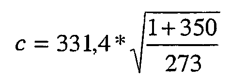
- The speed of sound is 500 m/s which gives that for λ/4 L3 should be approximately 1 m.
Part part 21 to a frequency close to 110 Hz andpart 23 close to 140 Hz. The above-mentioned calculation λ/4 in order to place the inlet of the pipes at pressure maximum gives that L2 ofpart 21 is 1.14 meters and L4 ofpart 23 is 0.89 meters. - Figure 7 shows a simplified graph of a calculated attenuating effect of an
attenuation element 20 in the low frequency area. In the previous example, the center frequency 125 Hz corresponds to thecentre 71 of the attenuation frequency band. The firstreactive part 21 corresponds to the left 70 curve of an attenuation effect with a centre frequency close to 110 Hz. The secondreactive part 22 corresponds to the right 72 curve of an attenuation effect with a centre frequency close to 125 Hz. It is beneficial to trim the acoustic performance of each attenuation element such that the total attenuation effect of the element, in the low frequency area, has flat top 73 corresponding to a certain damping measured in dB. - Figure 8 shows a simplified graph of the attenuation effect in the low frequency area of a sound reduction system comprising attenuation elements supplied according to the invention. Each of the
curves 80, 81 and 82 corresponds to anattenuation element 20. The attenuation effect of eachelement 20 may result in damping effects with different amplitudes measured in dB, this in contrast to the figure, which shows a system withattenuation elements 20 withsimilar amplitude 80, 81 and 82 for its band of frequencies. One important advantage of a method according to the invention is that it enables a user to adapt the total attenuation effect of each of theattenuation elements 80, 81 and 82 to the corresponding sound effect of the highpower combustion engine 4. - It should be understood that the elements and individual devices has a total attenuating effect greater than, if each attenuating effect would be added one by one to a total effect. The reason for that is that the elements and devices work together as a sound attenuation system. One acoustic effect that the invention makes use of is that one may introduce reflective waves by adding elements with
resistive parts 21, that has a reflective character in the low frequency area, or individual resistive devices at suitable positions. Such suitable positions are odd numbers of 1/4 of desired wavelengths for attenuation. - The attenuation elements 20a and 20b, as well as
individual devices step 8 such that the total attenuation effect of theattenuation elements 80, 81 and 82 and the attenuation effect of individual devices match certain bands the frequency spectra of the corresponding sound effect of the highpower combustion engine 4. Auser 14 may try different combinations of individual devices andattenuation elements 20 during the repeating step 10 in order to achieve not only sufficient sound attenuation, but also to model the attenuation system such that it may be supplied to the exhaust system in a cost effective manner. - The attenuating effect in the
high frequency 62 area of each element is mainly achieved by theresistive part 22. The calculation of the attenuating effect is made such that an estimated attenuated effect comprises a band of frequencies corresponding tointermediate frequencies 60 of anelement 20. Such a contribution to frequencies of anelement 20 is calculated by use of four-pole theory and by use of power flow models. Eachelement 20 contributes to attenuation in the low frequencies, intermediate frequencies and high frequencies. The inventors have found that it is beneficial to use a cut-on frequency to determine at what frequency the calculation should be based on four-pole theory or power flow models. The cut-on frequency depends on the cross-section area of transport system and the speed of sound fo(A,c). The cut-on frequency is typically calculated as:
where c is the speed of sound and d the diameter of the transport system at the element. According to Figure 6, below the cut-on frequency, the plane wave area, the attenuating effect of the element is mainly coming from thereactive parts - In one embodiment the cut-on frequency determines that it is only the contribution from four-pole theory that is used in the calculating step 9 to add to the calculated attenuated effect below the cut-on frequency for each of the
attenuation elements 20. And similar, in the same possible embodiment, the cut-on frequency determines that only the contribution from power flow models is used in the calculating step 9 to add to the calculated attenuated effect above the cut-on frequency. - Above the cut-on frequency, which is in the middle of the
intermediate frequencies 60 of Figure 6, the attenuating effect of a real world attenuating element is mainly coming from theresistive part 22. It should be noted that the attenuated effect in the high frequency area of theresistive part 22 is not depending on the position of the element. Nor is the acoustic effect of the single attenuating devices with resistive character depending on position. However, it is beneficial to place at least some resistive attenuating devices before apossible boiler 42 or heat exchanger. - It is beneficial to position the
attenuation elements 20 after apossible boiler 42 or heat exchanger. One reason is that commonly there are more straight pipes available after such aboiler 42. Another reason is that the temperature of the exhaust gases drops after aboiler 42 and heat exchanger. This means that the speed of sound is reduced after the boiler. This in turns means that to tune anelement 20 for attenuation at a certain center frequency, such as 125 Hz, results in that the required total length of theelement 20 is less after theboiler 42 than before the boiler.
Claims (10)
- A method for supplying a system for sound attenuation of noise relating to an exhaust system (1) of exhaust gases from a high power combustion engine (4), such as the exhaust system (1) at a ship (2) or power plant, characterized in that the method comprises the steps of:- adding (7) to a model of the exhaust system, by means of a computing device (13), a plurality of elements (20a, 20b) where each element comprises a first reactive part (21), a resistive part (22) and a second reactive part (23);- inserting (8) into the model, by means of the computing device (13), at least one single attenuating device (44, 45);- calculating (9), by means of the computing device (13), an attenuating effect of the elements (20a, 20b) and an attenuating effect of the at least one single attenuating device (44, 45) relating to a sound pressure level of the high power combustion engine (4);- repeating (10) the inserting and calculating step, until sufficient attenuation is achieved;- assembling (11) the system for sound attenuation, such that it comprises a plurality of real-world elements and at least one real-world single attenuating device mounted as channel parts along the exhaust system, wherein a measured noise level at the close vicinity of the outlet is below a desired noise level.
- A method according to claim 1 characterized in that a contribution to an estimated attenuated effect comprises a band of frequencies corresponding to intermediate frequencies (60) of an element (20).
- A method according to claim 2 characterized in that the contribution to the estimated attenuated effect from intermediate frequencies of an element (20) are calculated by use of four-pole theory and by use of power flow models.
- A method according to claim 1 or 3 characterized in that the at least one single reactive attenuating device (45) is positioned at an odd number of a quarter of a wavelength from a distinct impedance, such as an area increase (46), where the wavelength is the single attenuating device's tuned frequency.
- A method according to claim 4 with the additional step of calculating a pressure drop along the exhaust system (1).
- A method according to any previous claim characterized in that the minimum length of the exhaust system is 8 meters, the effect of the combustion engine (4) is greater than 500 kW.
- A method according to claim 6 where the exhaust system (1) comprises a heat exchanger or boiler (5, 42), which reduces the temperature of the exhaust gas in the exhaust system (1) and therefore the wavelength of the sound decreases after the heat exchanger or boiler (5, 42), and the at least one single attenuating device is positioned in an odd number of a quarter of a wavelength from the outlet of the heat exchanger or boiler (5, 42), where the wavelength is the single attenuating device's tuned frequency.
- The use of the method according to claim 1.
- A computer program stored on a media loadable into the memory of a computing device (13) characterized in that the computer program is capable of executing any of the steps according to claim 1.
- An elongated exhaust system of exhaust gases from a high power combustion engine (4) characterized that a system for sound attenuation (47) of noise is supplied to the exhaust system according the method of claim 1.
Applications Claiming Priority (2)
| Application Number | Priority Date | Filing Date | Title |
|---|---|---|---|
| SE0303613A SE526680C2 (en) | 2003-12-31 | 2003-12-31 | Procedure for reducing noise in a high-power internal combustion engine |
| PCT/SE2004/001898 WO2005064127A1 (en) | 2003-12-31 | 2004-12-16 | A method for reducing noise of a high power combustion engine |
Publications (2)
| Publication Number | Publication Date |
|---|---|
| EP1704306A1 EP1704306A1 (en) | 2006-09-27 |
| EP1704306B1 true EP1704306B1 (en) | 2007-06-20 |
Family
ID=30768920
Family Applications (1)
| Application Number | Title | Priority Date | Filing Date |
|---|---|---|---|
| EP04809071A Expired - Lifetime EP1704306B1 (en) | 2003-12-31 | 2004-12-16 | A method for reducing noise of a high power combustion engine |
Country Status (6)
| Country | Link |
|---|---|
| US (1) | US20070240933A1 (en) |
| EP (1) | EP1704306B1 (en) |
| AT (1) | ATE365266T1 (en) |
| DE (1) | DE602004007163T2 (en) |
| SE (1) | SE526680C2 (en) |
| WO (1) | WO2005064127A1 (en) |
Cited By (1)
| Publication number | Priority date | Publication date | Assignee | Title |
|---|---|---|---|---|
| WO2014076355A1 (en) | 2012-11-15 | 2014-05-22 | Wärtsilä Finland Oy | An exhaust gas noise attenuator unit for internal combustion piston engine |
Families Citing this family (5)
| Publication number | Priority date | Publication date | Assignee | Title |
|---|---|---|---|---|
| KR100969378B1 (en) * | 2008-03-31 | 2010-07-09 | 현대자동차주식회사 | Exhaust gas filter |
| GB2528950A (en) | 2014-08-06 | 2016-02-10 | Aaf Ltd | Sound suppression apparatus |
| US10781732B2 (en) | 2015-05-25 | 2020-09-22 | Wärtsilä Finland Oy | Acoustic attenuator for damping pressure vibrations in an exhaust system of an engine, an acoustic attenuation system using the attenuators, and method of damping pressure vibrations in an exhaust system of an engine |
| DK179246B1 (en) * | 2016-03-31 | 2018-03-05 | Ap Moeller Maersk As | Container ship |
| JP7422402B2 (en) * | 2020-10-29 | 2024-01-26 | 学校法人東海大学 | thermoacoustic silencer |
Family Cites Families (6)
| Publication number | Priority date | Publication date | Assignee | Title |
|---|---|---|---|---|
| US2826261A (en) * | 1956-08-30 | 1958-03-11 | Oliver C Eckel | Acoustical control apparatus |
| US4371054A (en) * | 1978-03-16 | 1983-02-01 | Lockheed Corporation | Flow duct sound attenuator |
| JPH0544503Y2 (en) * | 1988-07-29 | 1993-11-11 | ||
| EP0895562B1 (en) * | 1996-04-22 | 2000-07-05 | Wilhelmus Lambertus Arnoldus Meusen | Exhaust assembly for use with combustion engines, and vehicle provided with such assembly |
| SE9604664L (en) * | 1996-12-19 | 1998-01-19 | Flaekt Ab | Device and method of noise reduction in a gaseous medium transport system and use of the device in a ship exhaust system |
| US6454047B1 (en) * | 2000-10-17 | 2002-09-24 | Bbnt Solutions Llc | System and method for phases noise attenuation |
-
2003
- 2003-12-31 SE SE0303613A patent/SE526680C2/en not_active IP Right Cessation
-
2004
- 2004-12-16 DE DE602004007163T patent/DE602004007163T2/en not_active Expired - Lifetime
- 2004-12-16 EP EP04809071A patent/EP1704306B1/en not_active Expired - Lifetime
- 2004-12-16 WO PCT/SE2004/001898 patent/WO2005064127A1/en not_active Ceased
- 2004-12-16 US US10/584,687 patent/US20070240933A1/en not_active Abandoned
- 2004-12-16 AT AT04809071T patent/ATE365266T1/en not_active IP Right Cessation
Cited By (1)
| Publication number | Priority date | Publication date | Assignee | Title |
|---|---|---|---|---|
| WO2014076355A1 (en) | 2012-11-15 | 2014-05-22 | Wärtsilä Finland Oy | An exhaust gas noise attenuator unit for internal combustion piston engine |
Also Published As
| Publication number | Publication date |
|---|---|
| SE0303613L (en) | 2005-07-01 |
| SE0303613D0 (en) | 2003-12-31 |
| ATE365266T1 (en) | 2007-07-15 |
| US20070240933A1 (en) | 2007-10-18 |
| DE602004007163T2 (en) | 2008-02-21 |
| SE526680C2 (en) | 2005-10-25 |
| EP1704306A1 (en) | 2006-09-27 |
| WO2005064127A1 (en) | 2005-07-14 |
| DE602004007163D1 (en) | 2007-08-02 |
Similar Documents
| Publication | Publication Date | Title |
|---|---|---|
| Parrott et al. | Parallel-element liner impedances for improved absorption of broadband sound in ducts | |
| Kabral et al. | A compact silencer for the control of compressor noise | |
| CN106015818A (en) | Noise elimination energy-saving pipeline | |
| Morel et al. | Fluid dynamic and acoustic modeling of concentric-tube resonators/silencers | |
| EP1715238B1 (en) | Double throat pulsation dampener for a compressor | |
| Das et al. | A novel design for muffler chambers by incorporating baffle plate | |
| US20070240933A1 (en) | Method for Reducing Noise of a High Power Combustion Engine | |
| Christopher George et al. | Energy efficient design and modification of an automotive exhaust muffler for optimum noise, transmission loss, insertion loss and back pressure: A review | |
| Hou et al. | Case study: numerical study of the noise reduction characteristics of corrugated perforated pipe mufflers | |
| Kim et al. | Acoustic performance of a Helmholtz resonator with flow | |
| Jatola et al. | Analysis of noise level with convergent and divergent shape of muffler and its impact on noise pollution | |
| Allam et al. | Modeling and testing of after-treatment devices | |
| Torregrosa et al. | Assessment of acoustic reciprocity and conservativeness in exhaust aftertreatment systems | |
| Ducret | Studies of sound generation and propagation in flow ducts | |
| Cambow et al. | Design and Analysis of Core Chamber of Muffler [J] | |
| Hou et al. | Case study: Noise attenuating performance of perforated corrugated lined straight-through perforated pipe-resistant muffler | |
| Chaudhari et al. | Investigation of geometrical parameter on performance of muffler using CFD analysis | |
| Kurze et al. | Silencers | |
| He et al. | Acoustic Attenuation Prediction of Perforated Reactive and Dissipative Mufflers With Flow by Using Frequency-Domain Linearized Navier-Stokes Equations. | |
| Schram et al. | Innovative noise control in ducts | |
| Jatola et al. | Enhancement of Low-Frequency Noise for Muffler by Optimizing the Space between Three 1-Degrees of Freedom Helmholtz Resonator | |
| Taratorin et al. | Acoustic and mass characteristics of plate silencers with wedge-shaped outlet fairings | |
| Anasune et al. | Numerical and experimental analysis of flow–acoustic interaction in a hybrid muffler incorporating half-elliptical baffles | |
| Donkin | Measurement and Simulation of Aeroacoustic Sources Generated by Elementary Muffler Components | |
| Salunkhe | EVALUATION OF DOUBLE EXPANSION CHAMBER REACTIVE MUFFLER FOR ACOUSTIC ANALYSIS |
Legal Events
| Date | Code | Title | Description |
|---|---|---|---|
| PUAI | Public reference made under article 153(3) epc to a published international application that has entered the european phase |
Free format text: ORIGINAL CODE: 0009012 |
|
| 17P | Request for examination filed |
Effective date: 20060707 |
|
| AK | Designated contracting states |
Kind code of ref document: A1 Designated state(s): AT BE BG CH CY CZ DE DK EE ES FI FR GB GR HU IE IS IT LI LT LU MC NL PL PT RO SE SI SK TR |
|
| GRAP | Despatch of communication of intention to grant a patent |
Free format text: ORIGINAL CODE: EPIDOSNIGR1 |
|
| DAX | Request for extension of the european patent (deleted) | ||
| GRAS | Grant fee paid |
Free format text: ORIGINAL CODE: EPIDOSNIGR3 |
|
| GRAA | (expected) grant |
Free format text: ORIGINAL CODE: 0009210 |
|
| AK | Designated contracting states |
Kind code of ref document: B1 Designated state(s): AT BE BG CH CY CZ DE DK EE ES FI FR GB GR HU IE IS IT LI LT LU MC NL PL PT RO SE SI SK TR |
|
| PG25 | Lapsed in a contracting state [announced via postgrant information from national office to epo] |
Ref country code: LI Free format text: LAPSE BECAUSE OF FAILURE TO SUBMIT A TRANSLATION OF THE DESCRIPTION OR TO PAY THE FEE WITHIN THE PRESCRIBED TIME-LIMIT Effective date: 20070620 Ref country code: CH Free format text: LAPSE BECAUSE OF FAILURE TO SUBMIT A TRANSLATION OF THE DESCRIPTION OR TO PAY THE FEE WITHIN THE PRESCRIBED TIME-LIMIT Effective date: 20070620 |
|
| REG | Reference to a national code |
Ref country code: GB Ref legal event code: FG4D |
|
| REG | Reference to a national code |
Ref country code: CH Ref legal event code: EP |
|
| REG | Reference to a national code |
Ref country code: IE Ref legal event code: FG4D |
|
| REF | Corresponds to: |
Ref document number: 602004007163 Country of ref document: DE Date of ref document: 20070802 Kind code of ref document: P |
|
| RAP2 | Party data changed (patent owner data changed or rights of a patent transferred) |
Owner name: WAERTSILAE FINLAND OY |
|
| REG | Reference to a national code |
Ref country code: SE Ref legal event code: TRGR |
|
| PG25 | Lapsed in a contracting state [announced via postgrant information from national office to epo] |
Ref country code: AT Free format text: LAPSE BECAUSE OF FAILURE TO SUBMIT A TRANSLATION OF THE DESCRIPTION OR TO PAY THE FEE WITHIN THE PRESCRIBED TIME-LIMIT Effective date: 20070620 Ref country code: PL Free format text: LAPSE BECAUSE OF FAILURE TO SUBMIT A TRANSLATION OF THE DESCRIPTION OR TO PAY THE FEE WITHIN THE PRESCRIBED TIME-LIMIT Effective date: 20070620 |
|
| NLT2 | Nl: modifications (of names), taken from the european patent patent bulletin |
Owner name: WAERTSILAE FINLAND OY Effective date: 20070926 |
|
| NLV1 | Nl: lapsed or annulled due to failure to fulfill the requirements of art. 29p and 29m of the patents act | ||
| REG | Reference to a national code |
Ref country code: CH Ref legal event code: PL |
|
| PG25 | Lapsed in a contracting state [announced via postgrant information from national office to epo] |
Ref country code: BE Free format text: LAPSE BECAUSE OF FAILURE TO SUBMIT A TRANSLATION OF THE DESCRIPTION OR TO PAY THE FEE WITHIN THE PRESCRIBED TIME-LIMIT Effective date: 20070620 |
|
| PG25 | Lapsed in a contracting state [announced via postgrant information from national office to epo] |
Ref country code: IS Free format text: LAPSE BECAUSE OF FAILURE TO SUBMIT A TRANSLATION OF THE DESCRIPTION OR TO PAY THE FEE WITHIN THE PRESCRIBED TIME-LIMIT Effective date: 20071020 Ref country code: SI Free format text: LAPSE BECAUSE OF FAILURE TO SUBMIT A TRANSLATION OF THE DESCRIPTION OR TO PAY THE FEE WITHIN THE PRESCRIBED TIME-LIMIT Effective date: 20070620 Ref country code: CZ Free format text: LAPSE BECAUSE OF FAILURE TO SUBMIT A TRANSLATION OF THE DESCRIPTION OR TO PAY THE FEE WITHIN THE PRESCRIBED TIME-LIMIT Effective date: 20070620 Ref country code: BG Free format text: LAPSE BECAUSE OF FAILURE TO SUBMIT A TRANSLATION OF THE DESCRIPTION OR TO PAY THE FEE WITHIN THE PRESCRIBED TIME-LIMIT Effective date: 20070920 Ref country code: NL Free format text: LAPSE BECAUSE OF FAILURE TO SUBMIT A TRANSLATION OF THE DESCRIPTION OR TO PAY THE FEE WITHIN THE PRESCRIBED TIME-LIMIT Effective date: 20070620 Ref country code: ES Free format text: LAPSE BECAUSE OF FAILURE TO SUBMIT A TRANSLATION OF THE DESCRIPTION OR TO PAY THE FEE WITHIN THE PRESCRIBED TIME-LIMIT Effective date: 20071001 Ref country code: PT Free format text: LAPSE BECAUSE OF FAILURE TO SUBMIT A TRANSLATION OF THE DESCRIPTION OR TO PAY THE FEE WITHIN THE PRESCRIBED TIME-LIMIT Effective date: 20071120 |
|
| EN | Fr: translation not filed | ||
| PG25 | Lapsed in a contracting state [announced via postgrant information from national office to epo] |
Ref country code: LT Free format text: LAPSE BECAUSE OF FAILURE TO SUBMIT A TRANSLATION OF THE DESCRIPTION OR TO PAY THE FEE WITHIN THE PRESCRIBED TIME-LIMIT Effective date: 20070620 Ref country code: SK Free format text: LAPSE BECAUSE OF FAILURE TO SUBMIT A TRANSLATION OF THE DESCRIPTION OR TO PAY THE FEE WITHIN THE PRESCRIBED TIME-LIMIT Effective date: 20070620 |
|
| PLBE | No opposition filed within time limit |
Free format text: ORIGINAL CODE: 0009261 |
|
| STAA | Information on the status of an ep patent application or granted ep patent |
Free format text: STATUS: NO OPPOSITION FILED WITHIN TIME LIMIT |
|
| PG25 | Lapsed in a contracting state [announced via postgrant information from national office to epo] |
Ref country code: GR Free format text: LAPSE BECAUSE OF FAILURE TO SUBMIT A TRANSLATION OF THE DESCRIPTION OR TO PAY THE FEE WITHIN THE PRESCRIBED TIME-LIMIT Effective date: 20070921 Ref country code: DK Free format text: LAPSE BECAUSE OF FAILURE TO SUBMIT A TRANSLATION OF THE DESCRIPTION OR TO PAY THE FEE WITHIN THE PRESCRIBED TIME-LIMIT Effective date: 20070620 |
|
| 26N | No opposition filed |
Effective date: 20080325 |
|
| PG25 | Lapsed in a contracting state [announced via postgrant information from national office to epo] |
Ref country code: RO Free format text: LAPSE BECAUSE OF FAILURE TO SUBMIT A TRANSLATION OF THE DESCRIPTION OR TO PAY THE FEE WITHIN THE PRESCRIBED TIME-LIMIT Effective date: 20070620 |
|
| PG25 | Lapsed in a contracting state [announced via postgrant information from national office to epo] |
Ref country code: MC Free format text: LAPSE BECAUSE OF NON-PAYMENT OF DUE FEES Effective date: 20071231 Ref country code: FR Free format text: LAPSE BECAUSE OF FAILURE TO SUBMIT A TRANSLATION OF THE DESCRIPTION OR TO PAY THE FEE WITHIN THE PRESCRIBED TIME-LIMIT Effective date: 20080222 |
|
| PG25 | Lapsed in a contracting state [announced via postgrant information from national office to epo] |
Ref country code: IE Free format text: LAPSE BECAUSE OF NON-PAYMENT OF DUE FEES Effective date: 20071217 |
|
| PG25 | Lapsed in a contracting state [announced via postgrant information from national office to epo] |
Ref country code: EE Free format text: LAPSE BECAUSE OF FAILURE TO SUBMIT A TRANSLATION OF THE DESCRIPTION OR TO PAY THE FEE WITHIN THE PRESCRIBED TIME-LIMIT Effective date: 20070620 |
|
| PG25 | Lapsed in a contracting state [announced via postgrant information from national office to epo] |
Ref country code: CY Free format text: LAPSE BECAUSE OF FAILURE TO SUBMIT A TRANSLATION OF THE DESCRIPTION OR TO PAY THE FEE WITHIN THE PRESCRIBED TIME-LIMIT Effective date: 20070620 |
|
| GBPC | Gb: european patent ceased through non-payment of renewal fee |
Effective date: 20081216 |
|
| PG25 | Lapsed in a contracting state [announced via postgrant information from national office to epo] |
Ref country code: LU Free format text: LAPSE BECAUSE OF NON-PAYMENT OF DUE FEES Effective date: 20071216 |
|
| PG25 | Lapsed in a contracting state [announced via postgrant information from national office to epo] |
Ref country code: HU Free format text: LAPSE BECAUSE OF FAILURE TO SUBMIT A TRANSLATION OF THE DESCRIPTION OR TO PAY THE FEE WITHIN THE PRESCRIBED TIME-LIMIT Effective date: 20071221 Ref country code: TR Free format text: LAPSE BECAUSE OF FAILURE TO SUBMIT A TRANSLATION OF THE DESCRIPTION OR TO PAY THE FEE WITHIN THE PRESCRIBED TIME-LIMIT Effective date: 20070620 |
|
| PG25 | Lapsed in a contracting state [announced via postgrant information from national office to epo] |
Ref country code: GB Free format text: LAPSE BECAUSE OF NON-PAYMENT OF DUE FEES Effective date: 20081216 |
|
| PGFP | Annual fee paid to national office [announced via postgrant information from national office to epo] |
Ref country code: FI Payment date: 20161215 Year of fee payment: 13 |
|
| PG25 | Lapsed in a contracting state [announced via postgrant information from national office to epo] |
Ref country code: FI Free format text: LAPSE BECAUSE OF NON-PAYMENT OF DUE FEES Effective date: 20171216 |
|
| PGFP | Annual fee paid to national office [announced via postgrant information from national office to epo] |
Ref country code: DE Payment date: 20191210 Year of fee payment: 16 Ref country code: SE Payment date: 20191219 Year of fee payment: 16 |
|
| PGFP | Annual fee paid to national office [announced via postgrant information from national office to epo] |
Ref country code: IT Payment date: 20191230 Year of fee payment: 16 |
|
| REG | Reference to a national code |
Ref country code: DE Ref legal event code: R119 Ref document number: 602004007163 Country of ref document: DE |
|
| REG | Reference to a national code |
Ref country code: SE Ref legal event code: EUG |
|
| PG25 | Lapsed in a contracting state [announced via postgrant information from national office to epo] |
Ref country code: IT Free format text: LAPSE BECAUSE OF NON-PAYMENT OF DUE FEES Effective date: 20201216 |
|
| PG25 | Lapsed in a contracting state [announced via postgrant information from national office to epo] |
Ref country code: SE Free format text: LAPSE BECAUSE OF NON-PAYMENT OF DUE FEES Effective date: 20201217 Ref country code: DE Free format text: LAPSE BECAUSE OF NON-PAYMENT OF DUE FEES Effective date: 20210701 |