EP1703658B1 - MIMO detection ordering with adaptive modulation and scheduling method - Google Patents
MIMO detection ordering with adaptive modulation and scheduling method Download PDFInfo
- Publication number
- EP1703658B1 EP1703658B1 EP06005199A EP06005199A EP1703658B1 EP 1703658 B1 EP1703658 B1 EP 1703658B1 EP 06005199 A EP06005199 A EP 06005199A EP 06005199 A EP06005199 A EP 06005199A EP 1703658 B1 EP1703658 B1 EP 1703658B1
- Authority
- EP
- European Patent Office
- Prior art keywords
- detection order
- channels
- channel
- detection
- selecting
- Prior art date
- Legal status (The legal status is an assumption and is not a legal conclusion. Google has not performed a legal analysis and makes no representation as to the accuracy of the status listed.)
- Expired - Lifetime
Links
Images

Classifications
-
- H—ELECTRICITY
- H04—ELECTRIC COMMUNICATION TECHNIQUE
- H04L—TRANSMISSION OF DIGITAL INFORMATION, e.g. TELEGRAPHIC COMMUNICATION
- H04L1/00—Arrangements for detecting or preventing errors in the information received
- H04L1/02—Arrangements for detecting or preventing errors in the information received by diversity reception
- H04L1/06—Arrangements for detecting or preventing errors in the information received by diversity reception using space diversity
- H04L1/0618—Space-time coding
- H04L1/0675—Space-time coding characterised by the signaling
-
- A—HUMAN NECESSITIES
- A62—LIFE-SAVING; FIRE-FIGHTING
- A62C—FIRE-FIGHTING
- A62C3/00—Fire prevention, containment or extinguishing specially adapted for particular objects or places
- A62C3/02—Fire prevention, containment or extinguishing specially adapted for particular objects or places for area conflagrations, e.g. forest fires, subterranean fires
- A62C3/0257—Fire curtains, blankets, walls, fences
-
- H—ELECTRICITY
- H04—ELECTRIC COMMUNICATION TECHNIQUE
- H04L—TRANSMISSION OF DIGITAL INFORMATION, e.g. TELEGRAPHIC COMMUNICATION
- H04L1/00—Arrangements for detecting or preventing errors in the information received
- H04L1/0001—Systems modifying transmission characteristics according to link quality, e.g. power backoff
- H04L1/0002—Systems modifying transmission characteristics according to link quality, e.g. power backoff by adapting the transmission rate
- H04L1/0003—Systems modifying transmission characteristics according to link quality, e.g. power backoff by adapting the transmission rate by switching between different modulation schemes
-
- H—ELECTRICITY
- H04—ELECTRIC COMMUNICATION TECHNIQUE
- H04L—TRANSMISSION OF DIGITAL INFORMATION, e.g. TELEGRAPHIC COMMUNICATION
- H04L1/00—Arrangements for detecting or preventing errors in the information received
- H04L1/02—Arrangements for detecting or preventing errors in the information received by diversity reception
- H04L1/06—Arrangements for detecting or preventing errors in the information received by diversity reception using space diversity
- H04L1/0618—Space-time coding
- H04L1/0637—Properties of the code
- H04L1/0656—Cyclotomic systems, e.g. Bell Labs Layered Space-Time [BLAST]
Definitions
- the present invention relates generally to a user allocating apparatus and method in a multiple antenna mobile communication system, and in particular, to an apparatus and method for allocating a user in a multiple antenna mobile communication system supporting multi-user diversity.
- a radio channel environment typically has low reliability due to multipath interference, shadowing, wave attenuation, time-variant noise, and interference.
- the low reliability is an obstacle to increasing data rate.
- Major examples of many techniques developed to overcome this problem are error control coding and diversity. The former suppresses the effects of signal distortion and noise and the latter combats fading by independently receiving a plurality of signals experiencing fading.
- Time diversity achieves diversity in time by combining channel encoding with interleaving.
- frequency diversity signals are transmitted at different frequencies and thus in different paths.
- Multipath diversity is a scheme of achieving diversity by distinguishing multipath signals using different fading information.
- Spatial diversity is characterized in that both a transmitter and a receiver use a plurality of antennas and achieve diversity by using independent fading signals. Spatial diversity uses an antenna array.
- the error control coding technology and the diversity schemes for radio channels are not effective in satisfying the demands for high-speed data service, such as Internet connection and multimedia service. Since provisioning of the high-speed data service requires increased frequency efficiency, a mobile communication system having an antenna array is studied correspondingly.
- An antenna array system seeks to increase frequency efficiency in the space domain using multiple antennas at the transmitter and the receiver. Considering that time and frequency resources are limited, it is easy to further increase data rate by utilizing the space domain.
- Such antenna array systems are Vertical Bell Lab Layered Space Tome (V-BLAST) proposed by Bell Labs and space division multiplexing. Since each antenna transmits information independently, these antenna array systems are essentially Multi-Input Multi-Output (MIMO) systems.
- V-BLAST Vertical Bell Lab Layered Space Tome
- MIMO Multi-Input Multi-Output
- the channels between transmit antennas and receive antennas must have small correlation coefficients in the antenna array systems, so that information transmitted from the transmit antennas experience different channels and thus can be identified at a Mobile Station (MS). That is, a signal transmitted from each transmit antenna must have a different spatial characteristic, for identification at the MS, thereby leading to an increase of channel capacity.
- the antenna array systems are suitable for multipath signals with different spatial characteristics.
- the increase of capacity is not great in a Line Of Sight (LOS) environment, as compared to a single transmit/receive antenna system.
- LOS Line Of Sight
- the antenna array systems are feasible in a rich-scattering environment with multipath signals and low correlation coefficients between the transmit and receive antennas, i.e. in a diversity-effective environment.
- the use of an antenna array at the transmitter/receiver generally increases channel capacity.
- the channel capacity is dependent on whether the transmitter/receiver has knowledge of channel information. If both the transmitter and the receiver have channel information, the channel capacity is highest, and if neither the transmitter nor the receiver has channel information, the channel capacity is lowest. If only the receiver has channel information, the channel capacity increase is between the two cases.
- the transmitter estimates channel condition on its own, or receives feedback information about the channel condition.
- the channel information required in the antenna array system is the channel response between the transmit antennas and the receive antennas. Therefore, the channel information increases in proportion to the number of the transmit/receive antennas.
- the channel capacity increases in proportion to the number of available antennas in the transmitter/receiver.
- the amount of the feedback information increases with the number of the antennas. Accordingly, a need exists for increasing the channel capacity with a reduced amount of feedback information.
- a conventional Spatial Multiplexing (SM)-MIMO system adopts V-BLAST for reception.
- V-BLAST relies on interference cancellation which is performed by forward ordering detection or reverse ordering detection.
- a subchannel with the highest Signal-to-Interference Noise Ratio (SINR) is selected first of all at each step.
- the forward ordering detection is suitable for Equal Power (EP) and Equal Rate (ER) for each subchannel.
- the reverse ordering detection first detects a channel with a lower SINR. That is, detection is performed in an ascending order of SINR.
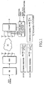
- FIG. 1 is a block diagram of a conventional SM-MIMO system using forward ordering detection and reverse ordering detection.
- the SM-MIMO system using adaptive modulation detects a signal on a substream-by-substream basis by V-BLAST.
- An effective Signal-to-Interference Ratio (SIR) and bit loading calculator selects the forward ordering or the reverse ordering according to SIR.
- the forward ordering and the reverse ordering are expressed as formulas in FIG. 1 , which are computed to determine an optimal detection order in the effective SIR and bit loading calculator.
- the forward ordering is based on the assumption of EP and ER, whereas the reverse ordering is based on the assumption of Power Allocation (PA) and Adaptive Rate (AR).
- PA Power Allocation
- AR Adaptive Rate
- the effective SIR and bit loading calculator provides the determined optimal detection order to a V-BLAST portion.
- the V-BLAST portion receives signals through a plurality of antennas according to the optimal detection order.
- the present invention solves at least the above problems and/or disadvantages and provides at least the advantages below.
- the present invention provides an apparatus and method for selecting an MS with a low error probability based on feedback information received from a plurality of MSs.
- the present invention also provides an apparatus and method for selecting an MS based on information about detection orders and bit loading patterns received from a plurality of MSs.
- the present invention further provides an apparatus and method for determining a detection order and a bit loading pattern that minimize error probability in an MS.
- the present invention additionally provides an apparatus and method for determining a detection order and a modulation scheme for each antenna which minimize error probability based on the minimum symbol distances of modulation schemes and SINR which actually affect the error probability, irrespective of a bit loading algorithm in each MS with an SIC receiver, and selecting an MS that minimizes the error probability of a system according to the detection orders and modulation schemes received from the MSs in a transmitter.
- the present invention provides an apparatus and method for selecting a user with the lowest error probability based on information about detection orders minimizing error probability received from a plurality of users.
- the average error probability of the system is decreased in two steps according to the present invention.
- Step 1 Each user determines a detection order minimizing error probability and a modulation scheme for each antenna corresponding to the detection order.
- a channel with the highest error probability affects an average error probability most significantly.
- the minimum symbol distance of a modulation scheme as well as received SINR is considered in selecting an optimal detection order.
- a detection order minimizing the average error probability determined by the received SINR and the minimum symbol distance of a modulation scheme is selected.
- the product of the minimum symbol distance of a selected modulation scheme and an effective SINR is calculated, and a detection order is selected such that the most transmit antennas (or channels) minimize the product. This is termed an optimal detection order. As signals are received in the optimal detection order, the average error probability is minimized.
- an optimal detection order is determined in the context of a system with EP and AR, while achieving performance close to that achieved by ordering with PA and AR using less feedback information.
- Step 2 A user with the lowest error probability is selected based on parameters and information about modulation schemes for respective antennas received from a plurality of users, and data is transmitted to the selected user using adaptive modulation for each antenna. That is, a user having the maximum of the products of minimum symbol distances and effective SINRs from a plurality of users is selected as one minimizing the error probability and modulation schemes are determined for the respective antennas according to a bit loading pattern received from the selected user.
- a formula for minimizing the average error probability expressed as the product of the minimum symbol distance of a modulation scheme and an effective SINR is derived as follows.
- the average error probability increases in proportion to the product of the minimum symbol distance of a modulation scheme and an effective SINR.
- g PSK M-ary Phase Shift Keying (PSK)
- g M M-ary Quadrature Amplitude Modulation (QAM)
- Equation (3) in the case of EP for each channel, division of the total SNR by the number of channels with non-zero bits results in the SNR of each channel (i.e. p/r).
- SIC SIC is used to obtain ⁇ k
- H denotes a channel matrix from which already-detected channels are cancelled by SIC.
- H h ⁇ 1 h ⁇ 2
- the above example is based on the assumption of a detection order in which the effective SIR of the signal from the first transmit antennas is measured earlier than that of the signal from the second transmit antenna. Yet, the opposite detection order is also available.
- the upper bound of the average error probability can be computed using a channel with the highest error probability by Equation (7).
- minimization of the average error probability is equivalent to maximization of the highest error probability, that is, g M ik • SINR ik .
- ⁇ is constant irrespective of detection orders
- a detection order that minimizes the average error probability is calculated by the following generalized formula and a corresponding modulation scheme for each antenna is determined according to Equation (8).
- SINRs are calculated over every possible detection order and then bit allocation is performed.
- a detection order minimizing the product of the minimum symbol distance of a modulation scheme, g M ik and an effective SINR, SINR ik is selected in the present invention.
- a detection order minimizing the product of the minimum symbol distance of a modulation scheme, g M tk and an effective SINR, SINR ik is selected between the forward ordering and the reverse ordering, without considering every possible detection order.
- modulation schemes and effective SIRs are calculated for transmit antennas sequentially for all possible detection orders, and then an optimal detection order is determined by Equation (7).
- the optimal detection order is provided to a V-BLAST portion so that signals can be received from the transmit antennas with a minimum average error probability.
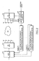
- FIG 2 is a block diagram of a transmitter and a receiver for determining an optimal detection order minimizing an average error probability in an SM-MIMO system using adaptive modulation and demodulation according to the present invention.
- An SIC receiver 214 detects signals received through a plurality of antennas on a substream-by-substream basis in an optimal detection order.
- the optimal detection order is determined by an effective SIR and bit loading calculator 216.
- the effective SIR and bit loading calculator 216 receives the indexes of all possible detection orders, for determining the optimal detection order. Upon receipt of the index of a detection order, the effective SIR and bit loading calculator 216 applies the detection order to Equation (7) and Equation (8). The effective SIR and bit loading calculator 216 calculates effective SIRs by Equation (3) and then bit loading for the respective channels (or transmit antennas) according to the detection order. The bit loading corresponds to a modulation scheme for each transmit antenna.
- the effective SIR and bit loading calculator 216 determines the optimal detection order by applying the effective SIRs and modulation schemes for the channels to Equation (7) for every detection order.
- the optimal detection order expressed as the products of minimum symbol distances and effective SINRs and a bit loading pattern resulting form the bit loading calculation are fed back to the BS.
- the BS receives information about detection orders and bit loading patterns from users.
- a detection order is expressed as products of minimum symbol distances and effective SINRs, and a bit loading pattern represents modulation schemes for respective transmit antennas.
- the BS compares the detection orders and selects a user having a maximum detection order value, that is, maximum products of minimum symbol distances and effective SINRs.
- the BS selects data to be transmitted to the selected user and transmits the selected data through the transmit antennas. Modulation schemes for the transmit antennas are determined according to the bit loading pattern of the selected user. That is, the transmit antennas transmit data by the modulation schemes determined by the selected user.
- Equation (9) max u user ⁇ r max i detection order min k T ⁇ x antenna ⁇ g M i ⁇ k ⁇ ⁇ i ⁇ k r i
- Equation (9) reveals that the BS selects a detection order having a maximum value among the received detection orders. That is, after checking the detection orders and modulation schemes for antennas received from the users, the BS selects a user that minimizes the average error probability of the system by Equation (9).
- each user calculates effective SINRs and the numbers of data bits over every possible detection order and selects a detection order that maximizes the number of channels having a minimum product of the minimum symbol distance of a modulation scheme and an effective SINR. Then a user with a maximum detection order value is selected and a modulation scheme is applied for each antenna for the selected user. In this manner, an average error probability is minimized.
- a user allocator 210 receives the detection orders and bit loading patterns from the users and selects a detection order having a maximum value as determined by Equation (9). Then the user allocator 210 allocates the user having the selected detection order. Data to be transmitted to the allocated user is provided to an Adaptive Modulator (AM) and multiplexer (MUX) 212.
- AM Adaptive Modulator
- MUX multiplexer
- the AM and MUX 212 multiplexes the user data according to the number of the transmit antennas and modulates the multiplexed data with the modulation schemes for the respective transmit antennas, determined according to the bit loading pattern of the allocated user, prior to transmission.
- the simulation is for an SM-MIMO system with EP and AM where each user uses a Zero-Forcing Ordered Successive Interference Cancellation (ZF-OSIC) receiver.
- ZF-OSIC Zero-Forcing Ordered Successive Interference Cancellation
- a detection order is selected as optimal among all possible detection orders, which maximizes the number of channels having a minimum product of the minimum symbol distance of a modulation scheme and an effective SINR.
- the modulation schemes and effective SINRs for the respective antennas corresponding to the optimal detection order are fed back to the transmitter.
- the transmitter thus selects a user which minimizes the average error probability and allocates as many bits as the modulation schemes to the respective corresponding transmit antennas, for data transmission to the user.
- FIG 3 is a graph comparing the performance of the present invention with a conventional scheme.
- the conventional scheme is V-BLAST with forwarding ordering detection, and the performance is measured as Bit Error Rate (BER) versus SNR with respect to changing numbers of users in the conventional scheme and the present invention. As the number of users increases, user diversity gain results, thereby increasing performance.
- the system of the present invention outperforms the conventional V-BLAST system.
- the present invention Compared to the V-BLAST scheme which transmits data at an equal rate through each antenna irrespective of channels and applies the forward ordering detection based on the SINRs of the channels, the present invention takes into account both the SINRs of the channels and associated modulation schemes over every possible detection order. After determining a detection order minimizing the average error probability and modulation schemes suitable for the channels, the transmitter selects a user that minimizes the average error probability and transmits data to the selected user with modulation schemes suitable for the user. Therefore, the present invention offers better performance than the conventional V-BLAST.
- a detection order that maximizes the number of channels with a minimum product of the minimum symbol distance of a modulation scheme and an effective SINR is selected for each user, thereby minimizing the average error probability of the user. Then a user having the minimum of the minimum average error probabilities is selected.
- a transmitter simply applies feedback information about a modulation scheme for each antenna suitable for the user calculated at the receiver of the user for data transmission to the user, thereby simplifying the transmission process.
- the present invention advantageously can determine a detection order with a reduced error rate, and offers the same performance as an optimal ordering detection, with a lesser amount of computation in terms of error rate.
Landscapes
- Engineering & Computer Science (AREA)
- Computer Networks & Wireless Communication (AREA)
- Signal Processing (AREA)
- Quality & Reliability (AREA)
- Life Sciences & Earth Sciences (AREA)
- Biodiversity & Conservation Biology (AREA)
- Ecology (AREA)
- Forests & Forestry (AREA)
- Health & Medical Sciences (AREA)
- Public Health (AREA)
- Business, Economics & Management (AREA)
- Emergency Management (AREA)
- Radio Transmission System (AREA)
- Mobile Radio Communication Systems (AREA)
Description
- The present invention relates generally to a user allocating apparatus and method in a multiple antenna mobile communication system, and in particular, to an apparatus and method for allocating a user in a multiple antenna mobile communication system supporting multi-user diversity.
- Unlike a wired channel environment, a radio channel environment typically has low reliability due to multipath interference, shadowing, wave attenuation, time-variant noise, and interference. The low reliability is an obstacle to increasing data rate. Major examples of many techniques developed to overcome this problem are error control coding and diversity. The former suppresses the effects of signal distortion and noise and the latter combats fading by independently receiving a plurality of signals experiencing fading.
- Diversity schemes are categorized into time diversity, frequency diversity, multipath diversity, and spatial diversity. Time diversity achieves diversity in time by combining channel encoding with interleaving. In frequency diversity, signals are transmitted at different frequencies and thus in different paths. Multipath diversity is a scheme of achieving diversity by distinguishing multipath signals using different fading information. Spatial diversity is characterized in that both a transmitter and a receiver use a plurality of antennas and achieve diversity by using independent fading signals. Spatial diversity uses an antenna array.
- However, the error control coding technology and the diversity schemes for radio channels are not effective in satisfying the demands for high-speed data service, such as Internet connection and multimedia service. Since provisioning of the high-speed data service requires increased frequency efficiency, a mobile communication system having an antenna array is studied correspondingly.
- An antenna array system seeks to increase frequency efficiency in the space domain using multiple antennas at the transmitter and the receiver. Considering that time and frequency resources are limited, it is easy to further increase data rate by utilizing the space domain. Such antenna array systems are Vertical Bell Lab Layered Space Tome (V-BLAST) proposed by Bell Labs and space division multiplexing. Since each antenna transmits information independently, these antenna array systems are essentially Multi-Input Multi-Output (MIMO) systems.
- To increase capacity with high frequency efficiency, the channels between transmit antennas and receive antennas must have small correlation coefficients in the antenna array systems, so that information transmitted from the transmit antennas experience different channels and thus can be identified at a Mobile Station (MS). That is, a signal transmitted from each transmit antenna must have a different spatial characteristic, for identification at the MS, thereby leading to an increase of channel capacity. The antenna array systems are suitable for multipath signals with different spatial characteristics. However, the increase of capacity is not great in a Line Of Sight (LOS) environment, as compared to a single transmit/receive antenna system. Hence, the antenna array systems are feasible in a rich-scattering environment with multipath signals and low correlation coefficients between the transmit and receive antennas, i.e. in a diversity-effective environment.
- The use of an antenna array at the transmitter/receiver generally increases channel capacity. The channel capacity is dependent on whether the transmitter/receiver has knowledge of channel information. If both the transmitter and the receiver have channel information, the channel capacity is highest, and if neither the transmitter nor the receiver has channel information, the channel capacity is lowest. If only the receiver has channel information, the channel capacity increase is between the two cases.
- To acquire the channel information, the transmitter estimates channel condition on its own, or receives feedback information about the channel condition. The channel information required in the antenna array system is the channel response between the transmit antennas and the receive antennas. Therefore, the channel information increases in proportion to the number of the transmit/receive antennas.
- In the antenna array system, including multiple transmit/receive antennas, the channel capacity increases in proportion to the number of available antennas in the transmitter/receiver. On the other hand, in the case of feedback of the channel information, the amount of the feedback information increases with the number of the antennas. Accordingly, a need exists for increasing the channel capacity with a reduced amount of feedback information.
- As previously described, a conventional Spatial Multiplexing (SM)-MIMO system adopts V-BLAST for reception. V-BLAST relies on interference cancellation which is performed by forward ordering detection or reverse ordering detection. In the forward ordering detection, a subchannel with the highest Signal-to-Interference Noise Ratio (SINR) is selected first of all at each step. The forward ordering detection is suitable for Equal Power (EP) and Equal Rate (ER) for each subchannel. In case of optimal bit allocation and power allocation, the reverse ordering detection first detects a channel with a lower SINR. That is, detection is performed in an ascending order of SINR.
-
FIG. 1 is a block diagram of a conventional SM-MIMO system using forward ordering detection and reverse ordering detection. The SM-MIMO system using adaptive modulation detects a signal on a substream-by-substream basis by V-BLAST. An effective Signal-to-Interference Ratio (SIR) and bit loading calculator selects the forward ordering or the reverse ordering according to SIR. The forward ordering and the reverse ordering are expressed as formulas inFIG. 1 , which are computed to determine an optimal detection order in the effective SIR and bit loading calculator. The forward ordering is based on the assumption of EP and ER, whereas the reverse ordering is based on the assumption of Power Allocation (PA) and Adaptive Rate (AR). The effective SIR and bit loading calculator provides the determined optimal detection order to a V-BLAST portion. The V-BLAST portion receives signals through a plurality of antennas according to the optimal detection order. - These conventional forward and reverse ordering detection techniques take into account only SINR in Successive Interference Cancellation (SIC). As a result, they are not efficient in terms of minimization of an average error probability determined by the minimum symbol distance of a modulation and a received SINR. Moreover, they operate for a single user and thus not suitable for a mobile communication system with multi-user diversity. Therefore, scheduling for a plurality of users is required to optimize error probability performance to support multi-use diversity in the conventional multiple antenna system.
- Long Bao Le et al: "On the performance of spatial multiplexing MIMO cellular systems with adaptive modulation and scheduling," Wireless Communications and Networking Conference, 2004, WCNC. 2004, IEEE Atlanta, GA, USA, 21-25 March 2004, Piscataway, NJ, USA, IEEE, vol. 2, 21 March 2004, pages 1282-1286, discloses detecting an ordering of a stream with the highest SINR fed back from a transmitter in order to achieve the highest possible spectral efficiency. In particular, a MIMO system using adaptive modulation and scheduling is described. Channel state information is available at the receiver side and separate channels are obtained via a singular value decomposition of a channel matrix. A post processing SINR for each stream is fed back to the transmitter to adapt the modulation level corresponding to each stream.
- The present invention solves at least the above problems and/or disadvantages and provides at least the advantages below.
- It is an object of the present invention to provide a user allocating apparatus and method for optimizing error probability performance in a multiple antenna system supporting multi-user diversity.
- This object is solved by the subject matter of the independent claims.
- Preferred embodiments are defined by the subject matter of the subclaims.
- The present invention provides an apparatus and method for selecting an MS with a low error probability based on feedback information received from a plurality of MSs. The present invention also provides an apparatus and method for selecting an MS based on information about detection orders and bit loading patterns received from a plurality of MSs. The present invention further provides an apparatus and method for determining a detection order and a bit loading pattern that minimize error probability in an MS. The present invention additionally provides an apparatus and method for determining a detection order and a modulation scheme for each antenna which minimize error probability based on the minimum symbol distances of modulation schemes and SINR which actually affect the error probability, irrespective of a bit loading algorithm in each MS with an SIC receiver, and selecting an MS that minimizes the error probability of a system according to the detection orders and modulation schemes received from the MSs in a transmitter.
- The present invention will become more apparent from the following detailed description when taken in conjunction with the accompanying drawings in which:
-
FIG. 1 is a block diagram of a transmitter and a receiver for determining a detection order in a conventional SM-MIMO system using adaptive modulation and demodulation; -
FIG. 2 is a block diagram of a transmitter and a receiver for determining a detection order in an SM-MIMO system using adaptive modulation and demodulation according to the present invention; and -
FIG. 3 is a graph comparing the performance of the present invention with a conventional scheme. - Preferred embodiments of the present invention will be described herein below with reference to the accompanying drawings. In the following description, well-known functions or constructions are not described in detail since they would obscure the invention in unnecessary detail.
- The present invention provides an apparatus and method for selecting a user with the lowest error probability based on information about detection orders minimizing error probability received from a plurality of users. The average error probability of the system is decreased in two steps according to the present invention.
- Step 1: Each user determines a detection order minimizing error probability and a modulation scheme for each antenna corresponding to the detection order. In general, a channel with the highest error probability affects an average error probability most significantly. Hence, it is optimal to select a detection order that minimizes the effects of the channel with the highest error probability. For this purpose, the minimum symbol distance of a modulation scheme as well as received SINR is considered in selecting an optimal detection order. In other words, a detection order minimizing the average error probability determined by the received SINR and the minimum symbol distance of a modulation scheme is selected.
- For each transmit antenna, hence, the product of the minimum symbol distance of a selected modulation scheme and an effective SINR is calculated, and a detection order is selected such that the most transmit antennas (or channels) minimize the product. This is termed an optimal detection order. As signals are received in the optimal detection order, the average error probability is minimized.
- In accordance with the present invention, an optimal detection order is determined in the context of a system with EP and AR, while achieving performance close to that achieved by ordering with PA and AR using less feedback information.
- Step 2: A user with the lowest error probability is selected based on parameters and information about modulation schemes for respective antennas received from a plurality of users, and data is transmitted to the selected user using adaptive modulation for each antenna. That is, a user having the maximum of the products of minimum symbol distances and effective SINRs from a plurality of users is selected as one minimizing the error probability and modulation schemes are determined for the respective antennas according to a bit loading pattern received from the selected user.
- Hereinbelow, a detailed description will be made of a generalization of a formula for determining an optimal detection order, and a structure for determining the optimal detection order by the generalized formula. An operation for selecting a user having the lowest error probability in a Base Station (BS) is also described.
- A formula for minimizing the average error probability expressed as the product of the minimum symbol distance of a modulation scheme and an effective SINR is derived as follows.
- Typically, the average error probability, Pb,k can converge to an exponential function within an error of 1dB, as expressed by Equation (1):

where C is a constant (=0.2), k is the index of a transmit antenna, M is a modulation order, gM is a constant being the minimum symbol distance of the modulation scheme, and SINRk is the effective SINR of a kth antenna. As noted from Equation (1), the average error probability increases in proportion to the product of the minimum symbol distance of a modulation scheme and an effective SINR. - For gM=M-ary Phase Shift Keying (PSK), and gM=M-ary Quadrature Amplitude Modulation (QAM), gPSK is expressed as Equation (2):

where M is 2 for the M-ary PHS and M is 16 for the M-ary QAM. - SINRk in Equation (1) is the product of the Signal-to-Noise Ratio (SNR) p/r of the kth channel, determined by its transmit power (SIR) and its noise, and the Signal-to-Interference Ratio (SIR) γk of the kth channel SINRk is expressed as Equation (3):

where ρ(=PT/σ2) is a total SNR and r is the number of channels with non-zero bits. - Referring to Equation (3), in the case of EP for each channel, division of the total SNR by the number of channels with non-zero bits results in the SNR of each channel (i.e. p/r). If SIC is used to obtain γk, H denotes a channel matrix from which already-detected channels are cancelled by SIC. For example, if H is expressed as two columns vectors h 1 and h 2 for two transmit/receive antennas, as Equation (4):


- If the effective SIR of a signal transmitted from one of the two transmit antennas is selected, the channel matrix and effective SIR of a signal transmitted from the other transmit antenna are given by Equation (6):

- The above example is based on the assumption of a detection order in which the effective SIR of the signal from the first transmit antennas is measured earlier than that of the signal from the second transmit antenna. Yet, the opposite detection order is also available.
- Since the effective SINR of each channel varies depending on the detection order used, the modulation scheme of each channel also changes according to the detection order. Therefore, effective SINRs are calculated over every possible detection order and the number of bits to be allocated to each channel is determined in order to reduce an actual error probability in the present invention. The average error probability is given as Equation (7):

where i is the index of a detection order. For MT transmit antennas, MT! detection orders exist. - The upper bound of the average error probability can be computed using a channel with the highest error probability by Equation (7). Hence, minimization of the average error probability is equivalent to maximization of the highest error probability, that is, gM
ik • SINRik . As the total SNR, ρ is constant irrespective of detection orders, a detection order that minimizes the average error probability is calculated by the following generalized formula and a corresponding modulation scheme for each antenna is determined according to Equation (8).
- As described above, effective SINRs are calculated over every possible detection order and then bit allocation is performed. A detection order minimizing the product of the minimum symbol distance of a modulation scheme, gM
ik and an effective SINR, SINRik is selected in the present invention. - In this way, the average error probability can be minimized. In the case where the number of antenna increases, a detection order minimizing the product of the minimum symbol distance of a modulation scheme, gM
tk and an effective SINR, SINRik is selected between the forward ordering and the reverse ordering, without considering every possible detection order. This method of determining an optimal detection order performs almost as well as the method of determining an optimal detection order among all possible detection orders. - In an apparatus for determining an optimal detection order according to the present invention, modulation schemes and effective SIRs are calculated for transmit antennas sequentially for all possible detection orders, and then an optimal detection order is determined by Equation (7). The optimal detection order is provided to a V-BLAST portion so that signals can be received from the transmit antennas with a minimum average error probability.
-
FIG 2 is a block diagram of a transmitter and a receiver for determining an optimal detection order minimizing an average error probability in an SM-MIMO system using adaptive modulation and demodulation according to the present invention. AnSIC receiver 214 detects signals received through a plurality of antennas on a substream-by-substream basis in an optimal detection order. The optimal detection order is determined by an effective SIR and bit loadingcalculator 216. - The effective SIR and bit loading
calculator 216 receives the indexes of all possible detection orders, for determining the optimal detection order. Upon receipt of the index of a detection order, the effective SIR and bit loadingcalculator 216 applies the detection order to Equation (7) and Equation (8). The effective SIR and bit loadingcalculator 216 calculates effective SIRs by Equation (3) and then bit loading for the respective channels (or transmit antennas) according to the detection order. The bit loading corresponds to a modulation scheme for each transmit antenna. - The effective SIR and bit loading
calculator 216 determines the optimal detection order by applying the effective SIRs and modulation schemes for the channels to Equation (7) for every detection order. The optimal detection order expressed as the products of minimum symbol distances and effective SINRs and a bit loading pattern resulting form the bit loading calculation are fed back to the BS. - A description will now be made of a method of selecting a user that minimizes an average error probability from the BS.
- The BS receives information about detection orders and bit loading patterns from users. A detection order is expressed as products of minimum symbol distances and effective SINRs, and a bit loading pattern represents modulation schemes for respective transmit antennas. The BS compares the detection orders and selects a user having a maximum detection order value, that is, maximum products of minimum symbol distances and effective SINRs. The BS then selects data to be transmitted to the selected user and transmits the selected data through the transmit antennas. Modulation schemes for the transmit antennas are determined according to the bit loading pattern of the selected user. That is, the transmit antennas transmit data by the modulation schemes determined by the selected user.
- The above user selection in the BS is generalized to Equation (9):

- Equation (9) reveals that the BS selects a detection order having a maximum value among the received detection orders. That is, after checking the detection orders and modulation schemes for antennas received from the users, the BS selects a user that minimizes the average error probability of the system by Equation (9).
- As described above, each user calculates effective SINRs and the numbers of data bits over every possible detection order and selects a detection order that maximizes the number of channels having a minimum product of the minimum symbol distance of a modulation scheme and an effective SINR. Then a user with a maximum detection order value is selected and a modulation scheme is applied for each antenna for the selected user. In this manner, an average error probability is minimized.
- In
FIG. 2 , auser allocator 210 receives the detection orders and bit loading patterns from the users and selects a detection order having a maximum value as determined by Equation (9). Then theuser allocator 210 allocates the user having the selected detection order. Data to be transmitted to the allocated user is provided to an Adaptive Modulator (AM) and multiplexer (MUX) 212. - The AM and
MUX 212 multiplexes the user data according to the number of the transmit antennas and modulates the multiplexed data with the modulation schemes for the respective transmit antennas, determined according to the bit loading pattern of the allocated user, prior to transmission. - The simulation was performed under the environment of Table 1.
Table 1 Bit loading Algorithm Chow's algorithm Modulation No Trans. BPSK. QPSK. 8PSK. 16QAM Detection ZF. V-BLAST. ZF-OSIC Active User 1,10. 100 Antenna Configuration 2 × 2 Channel Model Rayleigh flat fading - The simulation is for an SM-MIMO system with EP and AM where each user uses a Zero-Forcing Ordered Successive Interference Cancellation (ZF-OSIC) receiver.
- In the present invention, a detection order is selected as optimal among all possible detection orders, which maximizes the number of channels having a minimum product of the minimum symbol distance of a modulation scheme and an effective SINR. The modulation schemes and effective SINRs for the respective antennas corresponding to the optimal detection order are fed back to the transmitter. The transmitter thus selects a user which minimizes the average error probability and allocates as many bits as the modulation schemes to the respective corresponding transmit antennas, for data transmission to the user.
-
FIG 3 is a graph comparing the performance of the present invention with a conventional scheme. The conventional scheme is V-BLAST with forwarding ordering detection, and the performance is measured as Bit Error Rate (BER) versus SNR with respect to changing numbers of users in the conventional scheme and the present invention. As the number of users increases, user diversity gain results, thereby increasing performance. The system of the present invention outperforms the conventional V-BLAST system. - Compared to the V-BLAST scheme which transmits data at an equal rate through each antenna irrespective of channels and applies the forward ordering detection based on the SINRs of the channels, the present invention takes into account both the SINRs of the channels and associated modulation schemes over every possible detection order. After determining a detection order minimizing the average error probability and modulation schemes suitable for the channels, the transmitter selects a user that minimizes the average error probability and transmits data to the selected user with modulation schemes suitable for the user. Therefore, the present invention offers better performance than the conventional V-BLAST.
- In accordance with the present invention as described above, in a system with EP and AR, a detection order that maximizes the number of channels with a minimum product of the minimum symbol distance of a modulation scheme and an effective SINR is selected for each user, thereby minimizing the average error probability of the user. Then a user having the minimum of the minimum average error probabilities is selected. A transmitter simply applies feedback information about a modulation scheme for each antenna suitable for the user calculated at the receiver of the user for data transmission to the user, thereby simplifying the transmission process. The present invention advantageously can determine a detection order with a reduced error rate, and offers the same performance as an optimal ordering detection, with a lesser amount of computation in terms of error rate.
- While the invention has been shown and described with reference to certain preferred embodiments thereof, it will be understood by those skilled in the art that various changes in form and details may be made therein without departing from the scope of the invention as defined by the appended claims.
Claims (9)
- A method of allocating a terminal in a spatial multiplexing multi-input multi-output system, comprising the steps of:in each of a plurality of terminals, calculating a received signal-to-interference noise ratio, further referred to as SINR, of each of a plurality of channels over each of a plurality of possible detection orders;in each of said plurality of terminals, selecting the detection order that minimizes the highest of plurality of error probabilities of said plurality of channels, wherein for each channel its said error probability is based on a minimum symbol distance of a modulation scheme to be used in said channel, and on said received SINR of said channel;transmitting from each of said plurality of terminals to a base station, the selected detection order, and said modulation schemes to be used in each of said plurality of channels in accordance with said selected detection order;in said base station, selecting a terminal with lowest average of said plurality of error probabilities;in said base station, setting said modulation schemes to be used in each of said plurality of channels, according to said detection order determined by said selected terminal.
- The method of claim 1, wherein said detection order selecting step comprises said step of selecting said detection order by

- The method of claim 1, wherein said terminal selecting step comprises said step of selecting said terminal by

- A spatial multiplexing multi-input multi-output system, comprising a plurality of terminals and a base station, each of said terminals comprising:means for calculating a received signal-to-interference noise ratio, further referred to as SINR, of each of a plurality of channels over each of a plurality of possible detection orders,means for selecting the detection order that minimizes the highest of a plurality of error probabilities of said plurality of channels, wherein for each channel its said error probability is based on a minimum symbol distance of a modulation scheme to be used in said channel, and on said received SINR of said channel,means for transmitting to said base station the selected detection order and said modulation schemes to be used in each of said plurality of channels in accordance with said selected detection order; andsaid base station comprising:means for selecting a terminal with the lowest average of said plurality of error probabilities;means for setting said modulation schemes to be used in each of said plurality of channels, according to said detection order determined by said selected terminal.
- The spatial multiplexing multi-input multi-output system of claim 4, wherein said terminal selects said detection order by

- The spatial multiplexing multi-input multi-output system of claim 4, wherein said base station selects said terminal by

- The method of claim 1, wherein said step of selecting said detection order comprises:in each of said plurality of terminals, selecting said detection order that maximizes the number of channels with a minimum product of said minimum symbol distance of said modulation scheme and said SINR among said possible detection orders.transmitting from each of said plurality of terminals to said base station, information about said minimum symbol distance and said SINR in accordance with said selected detection order and information about said modulation schemes.
- The method of claim 7, wherein said step of selecting said terminal comprises:in said base station, creating a plurality of detection orders selected by said plurality of terminals based on a plurality of minimum symbol distances and a plurality of SINRs received from said plurality of terminals;in said base station, selecting a detection order that minimizes said average of said plurality of error probabilities among said detection orders.
- The method of claim 1, wherein said step of setting said modulation schemes further comprises:in said base station, transmitting data using said modulation schemes.
Applications Claiming Priority (1)
| Application Number | Priority Date | Filing Date | Title |
|---|---|---|---|
| KR1020050021190A KR100922958B1 (en) | 2005-03-14 | 2005-03-14 | User Allocation Device and Method in Multi-Antenna Mobile Communication System Supporting Multi-User Diversity |
Publications (2)
| Publication Number | Publication Date |
|---|---|
| EP1703658A1 EP1703658A1 (en) | 2006-09-20 |
| EP1703658B1 true EP1703658B1 (en) | 2009-11-04 |
Family
ID=36579205
Family Applications (1)
| Application Number | Title | Priority Date | Filing Date |
|---|---|---|---|
| EP06005199A Expired - Lifetime EP1703658B1 (en) | 2005-03-14 | 2006-03-14 | MIMO detection ordering with adaptive modulation and scheduling method |
Country Status (5)
| Country | Link |
|---|---|
| US (1) | US7532599B2 (en) |
| EP (1) | EP1703658B1 (en) |
| KR (1) | KR100922958B1 (en) |
| CN (1) | CN1862999B (en) |
| DE (1) | DE602006010128D1 (en) |
Families Citing this family (35)
| Publication number | Priority date | Publication date | Assignee | Title |
|---|---|---|---|---|
| US8036257B2 (en) * | 2006-05-05 | 2011-10-11 | Alcatel Lucent | Method of determining at least one transmit mode parameter for a multiple-input multiple-output system |
| AU2007284906A1 (en) | 2006-08-07 | 2008-02-21 | Interdigital Technology Corporation | Method, apparatus and system for implementing multi-user virtual multiple-input multiple-output |
| JP4267018B2 (en) * | 2006-10-06 | 2009-05-27 | レノボ・シンガポール・プライベート・リミテッド | Portable computer capable of wireless communication and method of detecting access point |
| US8849353B2 (en) * | 2007-04-27 | 2014-09-30 | Alcatel Lucent | Method of grouping users to reduce interference in MIMO-based wireless network |
| JP4900087B2 (en) * | 2007-07-02 | 2012-03-21 | 日本電気株式会社 | User selection method for multi-user MIMO communication |
| JP5322327B2 (en) | 2009-01-05 | 2013-10-23 | マーベル ワールド トレード リミテッド | Precoding of codebook for MIMO communication system |
| US8385441B2 (en) | 2009-01-06 | 2013-02-26 | Marvell World Trade Ltd. | Efficient MIMO transmission schemes |
| US8238483B2 (en) * | 2009-02-27 | 2012-08-07 | Marvell World Trade Ltd. | Signaling of dedicated reference signal (DRS) precoding granularity |
| US8457236B2 (en) * | 2009-04-06 | 2013-06-04 | Marvell World Trade Ltd. | Feedback strategies for multi-user MIMO communication systems |
| US8543063B2 (en) * | 2009-04-21 | 2013-09-24 | Marvell World Trade Ltd. | Multi-point opportunistic beamforming with selective beam attenuation |
| US8675794B1 (en) | 2009-10-13 | 2014-03-18 | Marvell International Ltd. | Efficient estimation of feedback for modulation and coding scheme (MCS) selection |
| US8917796B1 (en) | 2009-10-19 | 2014-12-23 | Marvell International Ltd. | Transmission-mode-aware rate matching in MIMO signal generation |
| US8325860B2 (en) | 2009-11-09 | 2012-12-04 | Marvell World Trade Ltd. | Asymmetrical feedback for coordinated transmission systems |
| US8761289B2 (en) * | 2009-12-17 | 2014-06-24 | Marvell World Trade Ltd. | MIMO feedback schemes for cross-polarized antennas |
| EP2522099A4 (en) * | 2010-01-07 | 2014-12-31 | Marvell World Trade Ltd | SIGNALING OF PRE-CODING GRANULARITIES FOR DEDICATED REFERENCE SIGNALS (DRS) |
| JP5258002B2 (en) | 2010-02-10 | 2013-08-07 | マーベル ワールド トレード リミテッド | Device, mobile communication terminal, chipset, and method in MIMO communication system |
| WO2011105500A1 (en) * | 2010-02-25 | 2011-09-01 | 日本電信電話株式会社 | Spatial multiplexing wireless transmission system, spatial multiplexing wireless transmission method, and computer program |
| US8687741B1 (en) | 2010-03-29 | 2014-04-01 | Marvell International Ltd. | Scoring hypotheses in LTE cell search |
| US8615052B2 (en) | 2010-10-06 | 2013-12-24 | Marvell World Trade Ltd. | Enhanced channel feedback for multi-user MIMO |
| JP2012100254A (en) | 2010-10-06 | 2012-05-24 | Marvell World Trade Ltd | Codebook subsampling for pucch feedback |
| US9048970B1 (en) | 2011-01-14 | 2015-06-02 | Marvell International Ltd. | Feedback for cooperative multipoint transmission systems |
| US8861391B1 (en) | 2011-03-02 | 2014-10-14 | Marvell International Ltd. | Channel feedback for TDM scheduling in heterogeneous networks having multiple cell classes |
| CN103548284B (en) | 2011-03-31 | 2017-07-21 | 马维尔国际贸易有限公司 | Channel feedback for cooperative multipoint transmission |
| KR101318609B1 (en) * | 2011-10-28 | 2013-10-15 | 세종대학교산학협력단 | Apparatus for Transmitting Data by Using Multi-Input Multi-Output and Method Thereof |
| US9020058B2 (en) | 2011-11-07 | 2015-04-28 | Marvell World Trade Ltd. | Precoding feedback for cross-polarized antennas based on signal-component magnitude difference |
| US8923427B2 (en) | 2011-11-07 | 2014-12-30 | Marvell World Trade Ltd. | Codebook sub-sampling for frequency-selective precoding feedback |
| WO2013068974A1 (en) | 2011-11-10 | 2013-05-16 | Marvell World Trade Ltd. | Differential cqi encoding for cooperative multipoint feedback |
| US9220087B1 (en) | 2011-12-08 | 2015-12-22 | Marvell International Ltd. | Dynamic point selection with combined PUCCH/PUSCH feedback |
| US8902842B1 (en) | 2012-01-11 | 2014-12-02 | Marvell International Ltd | Control signaling and resource mapping for coordinated transmission |
| CN104185954B (en) * | 2012-03-28 | 2016-09-14 | 华为技术有限公司 | Any precoder is used to carry out the system and method for Nonlinear M U-MIMO down channel precoding |
| EP2842361B1 (en) | 2012-04-27 | 2019-03-27 | Marvell World Trade Ltd. | Coordinated multipoint (comp) communication between base-stations and mobile communication terminals |
| WO2017183865A2 (en) * | 2016-04-17 | 2017-10-26 | 엘지전자 주식회사 | Method for transmitting signals by considering interferences in fed2d environment and apparatus therefor |
| CN107979396A (en) * | 2016-10-25 | 2018-05-01 | 索尼公司 | Communicator and method for Multi-User Dimension modulation |
| CN115412141B (en) * | 2022-08-18 | 2023-07-25 | 南京邮电大学 | Phase shift optimization method of IRS-assisted space shift keying modulation system |
| CN117614650B (en) * | 2023-10-26 | 2024-11-19 | 国网湖北省电力有限公司宜昌供电公司 | Concealed communication method and system of electric power Internet of things |
Family Cites Families (14)
| Publication number | Priority date | Publication date | Assignee | Title |
|---|---|---|---|---|
| CN1155190C (en) * | 2001-10-09 | 2004-06-23 | 华为技术有限公司 | Vertical Bell laboratory ranked space and time code array linear detecting method |
| US20030125040A1 (en) | 2001-11-06 | 2003-07-03 | Walton Jay R. | Multiple-access multiple-input multiple-output (MIMO) communication system |
| EP1337082B1 (en) * | 2002-02-14 | 2005-10-26 | Lucent Technologies Inc. | Receiver and method for multi-input multi-output iterative detection using feedback of soft estimates |
| US7076263B2 (en) | 2002-02-19 | 2006-07-11 | Qualcomm, Incorporated | Power control for partial channel-state information (CSI) multiple-input, multiple-output (MIMO) systems |
| KR100483387B1 (en) * | 2002-05-08 | 2005-04-14 | 재단법인서울대학교산학협력재단 | Wireless communication system employing multi-element antennas at both the transmitter and receiver and method thereof |
| GB0212165D0 (en) * | 2002-05-27 | 2002-07-03 | Nokia Corp | A wireless system |
| US7254192B2 (en) * | 2002-07-12 | 2007-08-07 | Texas Instruments Incorporated | Iterative detection in MIMO systems |
| EP1392017B1 (en) | 2002-08-21 | 2006-10-04 | Lucent Technologies Inc. | A MIMO radio telecommunication system using multilevel-coded modulation operative by iterative determination of soft estimates, and a corresponding method |
| WO2004034660A1 (en) * | 2002-10-10 | 2004-04-22 | Nokia Corporation | Channel estimation using expectation maximisation for space-time communications systems |
| US7317770B2 (en) * | 2003-02-28 | 2008-01-08 | Nec Laboratories America, Inc. | Near-optimal multiple-input multiple-output (MIMO) channel detection via sequential Monte Carlo |
| CN1860701B (en) * | 2003-10-01 | 2011-08-03 | 美国博通公司 | System and method for antenna selection |
| CA2490969C (en) * | 2004-01-02 | 2014-06-17 | Her Majesty In Right Of Canada As Represented By The Minister Of Industry, Through The Communications Research Centre Canada | Method for updating singular value decomposition of a transfer matrix |
| KR100713336B1 (en) | 2004-03-08 | 2007-05-04 | 삼성전자주식회사 | Signal Detection Order Determination Method in Mobile Communication System |
| CN100589597C (en) * | 2004-10-01 | 2010-02-10 | 新加坡科技研究局 | Method and system for determining signal vectors |
-
2005
- 2005-03-14 KR KR1020050021190A patent/KR100922958B1/en not_active Expired - Fee Related
-
2006
- 2006-03-14 DE DE602006010128T patent/DE602006010128D1/en not_active Expired - Lifetime
- 2006-03-14 CN CN2006100900000A patent/CN1862999B/en not_active Expired - Fee Related
- 2006-03-14 US US11/374,735 patent/US7532599B2/en not_active Expired - Fee Related
- 2006-03-14 EP EP06005199A patent/EP1703658B1/en not_active Expired - Lifetime
Also Published As
| Publication number | Publication date |
|---|---|
| EP1703658A1 (en) | 2006-09-20 |
| US20060203777A1 (en) | 2006-09-14 |
| DE602006010128D1 (en) | 2009-12-17 |
| US7532599B2 (en) | 2009-05-12 |
| CN1862999B (en) | 2010-04-14 |
| CN1862999A (en) | 2006-11-15 |
| KR100922958B1 (en) | 2009-10-22 |
| KR20060099763A (en) | 2006-09-20 |
Similar Documents
| Publication | Publication Date | Title |
|---|---|---|
| US7532599B2 (en) | Apparatus and method for allocating user in a multiple antenna mobile communication system supporting multi-user diversity | |
| US20220183019A1 (en) | Multi-User MIMO Systems and Methods | |
| US10243625B2 (en) | Rate-adaptive multiple input/multiple output (MIMO) systems | |
| JP4602641B2 (en) | Signal transmission system, signal transmission method and transmitter | |
| US7907677B2 (en) | Open loop MU-MIMO | |
| US8416872B2 (en) | Radio communication apparatus and a radio communication method | |
| US7103325B1 (en) | Adaptive modulation and coding | |
| US8233939B2 (en) | Multiuser sector micro diversity system | |
| US7526039B2 (en) | Method for deciding signal detection order in mobile communication system | |
| US20040171359A1 (en) | Power allocation in a communication system | |
| WO2008156319A2 (en) | Method of transmitting feedback information in wireless communication system |
Legal Events
| Date | Code | Title | Description |
|---|---|---|---|
| PUAI | Public reference made under article 153(3) epc to a published international application that has entered the european phase |
Free format text: ORIGINAL CODE: 0009012 |
|
| 17P | Request for examination filed |
Effective date: 20060314 |
|
| AK | Designated contracting states |
Kind code of ref document: A1 Designated state(s): AT BE BG CH CY CZ DE DK EE ES FI FR GB GR HU IE IS IT LI LT LU LV MC NL PL PT RO SE SI SK TR |
|
| AX | Request for extension of the european patent |
Extension state: AL BA HR MK YU |
|
| 17Q | First examination report despatched |
Effective date: 20061206 |
|
| AKX | Designation fees paid |
Designated state(s): DE FI FR GB IT SE |
|
| GRAP | Despatch of communication of intention to grant a patent |
Free format text: ORIGINAL CODE: EPIDOSNIGR1 |
|
| GRAS | Grant fee paid |
Free format text: ORIGINAL CODE: EPIDOSNIGR3 |
|
| GRAA | (expected) grant |
Free format text: ORIGINAL CODE: 0009210 |
|
| AK | Designated contracting states |
Kind code of ref document: B1 Designated state(s): DE FI FR GB IT SE |
|
| REG | Reference to a national code |
Ref country code: GB Ref legal event code: FG4D |
|
| REF | Corresponds to: |
Ref document number: 602006010128 Country of ref document: DE Date of ref document: 20091217 Kind code of ref document: P |
|
| REG | Reference to a national code |
Ref country code: SE Ref legal event code: TRGR |
|
| PLBE | No opposition filed within time limit |
Free format text: ORIGINAL CODE: 0009261 |
|
| STAA | Information on the status of an ep patent application or granted ep patent |
Free format text: STATUS: NO OPPOSITION FILED WITHIN TIME LIMIT |
|
| 26N | No opposition filed |
Effective date: 20100805 |
|
| REG | Reference to a national code |
Ref country code: FR Ref legal event code: PLFP Year of fee payment: 11 |
|
| REG | Reference to a national code |
Ref country code: FR Ref legal event code: PLFP Year of fee payment: 12 |
|
| REG | Reference to a national code |
Ref country code: FR Ref legal event code: PLFP Year of fee payment: 13 |
|
| PGFP | Annual fee paid to national office [announced via postgrant information from national office to epo] |
Ref country code: IT Payment date: 20200312 Year of fee payment: 15 Ref country code: DE Payment date: 20200220 Year of fee payment: 15 Ref country code: GB Payment date: 20200225 Year of fee payment: 15 Ref country code: FI Payment date: 20200220 Year of fee payment: 15 Ref country code: SE Payment date: 20200221 Year of fee payment: 15 |
|
| PGFP | Annual fee paid to national office [announced via postgrant information from national office to epo] |
Ref country code: FR Payment date: 20200221 Year of fee payment: 15 |
|
| REG | Reference to a national code |
Ref country code: DE Ref legal event code: R119 Ref document number: 602006010128 Country of ref document: DE |
|
| REG | Reference to a national code |
Ref country code: FI Ref legal event code: MAE |
|
| PG25 | Lapsed in a contracting state [announced via postgrant information from national office to epo] |
Ref country code: FI Free format text: LAPSE BECAUSE OF NON-PAYMENT OF DUE FEES Effective date: 20210314 |
|
| GBPC | Gb: european patent ceased through non-payment of renewal fee |
Effective date: 20210314 |
|
| PG25 | Lapsed in a contracting state [announced via postgrant information from national office to epo] |
Ref country code: SE Free format text: LAPSE BECAUSE OF NON-PAYMENT OF DUE FEES Effective date: 20210315 Ref country code: DE Free format text: LAPSE BECAUSE OF NON-PAYMENT OF DUE FEES Effective date: 20211001 Ref country code: FR Free format text: LAPSE BECAUSE OF NON-PAYMENT OF DUE FEES Effective date: 20210331 Ref country code: GB Free format text: LAPSE BECAUSE OF NON-PAYMENT OF DUE FEES Effective date: 20210314 |
|
| PG25 | Lapsed in a contracting state [announced via postgrant information from national office to epo] |
Ref country code: IT Free format text: LAPSE BECAUSE OF NON-PAYMENT OF DUE FEES Effective date: 20210314 |