EP1703510A1 - Disc cartridge - Google Patents
Disc cartridge Download PDFInfo
- Publication number
- EP1703510A1 EP1703510A1 EP04807365A EP04807365A EP1703510A1 EP 1703510 A1 EP1703510 A1 EP 1703510A1 EP 04807365 A EP04807365 A EP 04807365A EP 04807365 A EP04807365 A EP 04807365A EP 1703510 A1 EP1703510 A1 EP 1703510A1
- Authority
- EP
- European Patent Office
- Prior art keywords
- shutter
- disc
- cartridge
- opening
- shutter member
- Prior art date
- Legal status (The legal status is an assumption and is not a legal conclusion. Google has not performed a legal analysis and makes no representation as to the accuracy of the status listed.)
- Withdrawn
Links
Images






Classifications
-
- G—PHYSICS
- G11—INFORMATION STORAGE
- G11B—INFORMATION STORAGE BASED ON RELATIVE MOVEMENT BETWEEN RECORD CARRIER AND TRANSDUCER
- G11B23/00—Record carriers not specific to the method of recording or reproducing; Accessories, e.g. containers, specially adapted for co-operation with the recording or reproducing apparatus ; Intermediate mediums; Apparatus or processes specially adapted for their manufacture
- G11B23/02—Containers; Storing means both adapted to cooperate with the recording or reproducing means
- G11B23/03—Containers for flat record carriers
-
- G—PHYSICS
- G11—INFORMATION STORAGE
- G11B—INFORMATION STORAGE BASED ON RELATIVE MOVEMENT BETWEEN RECORD CARRIER AND TRANSDUCER
- G11B23/00—Record carriers not specific to the method of recording or reproducing; Accessories, e.g. containers, specially adapted for co-operation with the recording or reproducing apparatus ; Intermediate mediums; Apparatus or processes specially adapted for their manufacture
- G11B23/02—Containers; Storing means both adapted to cooperate with the recording or reproducing means
- G11B23/03—Containers for flat record carriers
- G11B23/0301—Details
- G11B23/0308—Shutters
Definitions
- This invention relates to a disc cartridge having housed therein a disc, such as an optical disc, used as an information recording medium.
- a disc cartridge which has rotationally housed therein a disc, such as an optical disc, used as an information recording medium, and which is loaded on a recording and/or reproducing apparatus as the disc is housed therein, has been put to extensive use.
- This sort of the disc cartridge protects the disc-shaped recording medium by housing it in a cartridge body member, while enabling facilitated insertion/ detachment of the disc for a recording and/or reproducing apparatus.
- the disc cartridge is designed to enable the disc to be loaded on the recording and/or reproducing apparatus, as the disc remains housed in the cartridge body member, there is formed in the cartridge body member a recording and/or reproducing aperture for exposing a part of the disc to outside across the inner and outer rims of the disc.
- the disc cartridge having the disc housed therein, is provided with a shutter member for closing the recording and/or reproducing aperture.
- This shutter member includes a rectangular flat-plate shaped shutter part, having the dimension sufficient to close the recording and/or reproducing aperture, and a support part 101 of a U-shaped cross-section, formed towards the proximal end of the shutter part.
- the shutter member has its support part introduced into a groove-shaped slide guide formed in the cartridge body unit, and hence the shutter member is slidable along a lateral surface of the cartridge body unit. In this manner, the shutter member may be slid so that its shutter part may open/close the recording and/or reproducing aperture.
- the shutter member includes, in a side of the support part thereof facing a lateral side of the cartridge body unit, a shutter opening/closing opening into which is inserted a shutter opening/closing member 100 adapted for opening/closing the shutter member.
- This shutter opening/closing member introduced into the shutter opening/closing opening, is provided to a main apparatus body unit of the disc recording and/or reproducing apparatus, and is formed by, for example, an elastic spring, exhibiting the flexibility.
- the shutter opening/closing member 100 includes a substantially chevron-shaped retention part 102 protruded on the movement trajectory of the shutter member for holding the so intruded disc cartridge in order to watch the intrusion of the disc cartridge.
- this retention part 102 is abutted against the foremost part of the support part 101 of the shutter member to flex the shutter opening/closing member 100.
- the shutter opening/closing member rides on the support part 101 to be slid thereon for intrusion into and engagement with the shutter opening/closing opening.
- the shutter opening/closing opening is regulated in the movement thereof along the slide guide part provided to the cartridge body unit to inhibit intrusion of the shutter member into the main apparatus body unit.
- the shutter member is moved relative to the cartridge body unit of the disc cartridge transported further into the main apparatus body unit, thereby opening the recording and/or reproducing aperture.
- the shutter member engaged by the shutter opening/closing member 100 and thereby prohibited from being moved further, is moved relative to the cartridge body unit of the disc cartridge being transported to outside the main apparatus body unit, such as to close the recording and/or reproducing opening.
- the shutter opening/closing member 100 When the cartridge body unit is ejected to outside the recording and/or reproducing apparatus, the shutter opening/closing member 100 is flexed to outside the cartridge body unit, due to the sliding of the shutter opening/closing opening, and hence the retention part is receded from the shutter opening/closing opening.
- the foremost part of the support part 101 of the shutter member which is the contact point of the shutter opening/closing member 100 with the shutter member, is square-shaped, with the consequence that the retention part 102 is abutted against the distal end of the support part 101 to interfere with smooth insertion and worsen the sense of insertion of the disc cartridge.
- the retention part 102 of the shutter opening/closing member 100 and the support part 101 of the shutter member colliding against each other, tend to deteriorate or cause wear of the two components, while dust and dirt also tend to be produced.
- the disc cartridge according to the present invention includes a disc, a cartridge body unit having the disc rotatably housed therein and including a recording and/or reproducing aperture for exposing a part of the disc to outside, and a shutter member slidably carried by the cartridge body unit,
- the shutter member includes a shutter opening/closing member provided to a recording and/or reproducing apparatus for sliding on the shutter member.
- the shutter member also includes an engagement opening engaged by the shutter opening/closing member.
- the shutter member operates for opening/closing the recording and/or reproducing aperture.
- the shutter member includes a collision buffering part for absorbing the shock of collision against the shutter opening/closing member.
- the shutter opening/closing member provided to the recording and/or reproducing apparatus, is abutted against the collision buffering part and, by being guided by this collision buffering part, smoothly rides on the shutter member so as to be slid thereon. Consequently, there is no catch between the end of the shutter member and the shutter opening/closing member of the recording and/or reproducing apparatus, thereby improving the sense of an inserting operation into the recording and/or reproducing apparatus and also protecting the shutter member and the shutter opening/closing member.
- a disc cartridge 1 of the present embodiment has rotationally housed therein an optical disc 2, as a disc used as an information recording medium.
- the disc cartridge 1 includes a cartridge body member 5, composed of paired upper and lower halves 3 and 4, abutted and connected together.
- the optical disc 2 is rotationally housed within this cartridge body member 5.
- the disc cartridge 1 has housed therein the optical disc 2, carrying video data or program data for playing a television game, and is formed to an extremely small size.
- This disc cartridge 1 has housed therein a small-sized optical disc 2, with a diameter of approximately 60 mm, and is formed to a size that can be held in one's palm.
- An upper cartridge half 3 and a lower cartridge half 4, forming the cartridge body member 5 for housing the optical disc 2, are formed by molding a synthetic resin material, and are abutted and connected to each other to form the cartridge body member 5.
- On the outer rims of the upper and lower cartridge halves 3, 4 are formed upstanding peripheral wall sections 3a, 4a, which are abutted to each other by abutting the upper and lower cartridge halves 3, 4 to each other to form a disc housing 6. Meanwhile, the upper and lower cartridge halves 3, 4 are coupled together by welding weld projections on the facing inner surfaces thereof by a welding technique, such as ultrasonic welding, to complete the cartridge body member 5.
- the cartridge body member 5, making up the disc cartridge 1 has a forward surface, as an inserting end side of the disc cartridge 1 into a disc drive device 50, in the form of an arcuate section 7, as shown in Figs.1 and 3.
- the arcuate section 7 is formed to a substantially semi-circular shape, with a constant radius R1, having the center of the optical disc 2, housed within the disc housing 6 of the cartridge body member 5, as a center PO, as shown in Fig.2. That is, the arcuate section 7 is formed as a semi-circle facing a semi-circle of the optical disc 2 housed within the cartridge body member 5.
- the facing lateral surfaces of the cartridge body member 5, continuing to the arcuate section 7 thereof, are formed as lateral sides parallel to each other, while the back surface thereof, lying on the opposite side of the arcuate section 7, is formed with a smoothly continuously curved section 10.
- the disc cartridge 1 has its front side, as an inserting end side, as the substantially semi-circular arcuate section 7, more strongly curved than the remaining surfaces, so that, when the disc cartridge 1 is inserted or ejected by a slot-in system via a cartridge inserting/ ejecting opening, formed in the disc drive device, the direction of insertion of the disc cartridge into the device can be discerned readily.
- the inserting direction can be discriminated with the feeling of the hand holding the disc cartridge 1.
- the present disc cartridge 1 can be inserted into the disc drive device of the slot-in type not only extremely readily but highly reliably, as will be explained later.
- the disc cartridge 1, embodying the present invention in which the inserting end side thereof is the substantially semi-circular arcuate section 7, with the back surface thereof, opposite to the arcuate section, being the curved section 10, the disc cartridge may further be reduced in size as compared to the optical disc 2 housed therein.
- a circular center opening 12 for exposing to outside a center opening 11, formed in the center of the optical disc 2, housed in the cartridge body member 5, and a neighboring area thereof, as shown in Figs.2 and 3.
- Into the center opening 12 is intruded a part of the disc rotating driving mechanism, provided to the disc drive device, adapted for loading the disc cartridge 1 thereon, such as a turntable.
- an aperture for an optical head 13 as a recording and/or reproducing aperture, as shown in Figs.2 and 3.
- the aperture for an optical head 13 is formed in one lateral surface 8 of the cartridge body member 5 to a rectangular shape and to a size sufficient to permit part of the signal recording area of the optical disc 2 in the cartridge body member 5 to be exposed to outside across the inner and outer rims of the disc. That is, the aperture for an optical head 13 is formed in the lateral side 8 which is the rectilinear planar surface other than the forward surface of the cartridge body member 5 in which has been formed the arcuate section 7. This aperture for an optical head 13 is closed by a shutter member 15 which will be explained subsequently.
- a guide groove 14 in which is guided a shutter opening member, as will be explained subsequently.
- the shutter member 15 for opening/ closing the aperture for an optical head 13 is formed by punching and bending a thin metal sheet or on molding the synthetic resin material.
- the shutter member 15 includes a rectangular flat-plate-shaped shutter part 16, formed to a rectangular shape of a dimension large enough to close the aperture for an optical head 13, and a support piece 17 formed on the proximal end of the shutter part 16 to a U-shaped cross-section.
- the shutter member 15 supports the upper cartridge half 3 of the cartridge body member 5 by the support piece 17 so that the shutter member is carried for movement in the directions of arrows A and B in Fig.2 for opening/closing the aperture for an optical head 13. That is, the shutter member 15 is mounted for movement to the cartridge body member 5, as the support piece 17 supports a slide guide part 18 formed by a fraction of the upstanding peripheral wall section 3 a of the upper cartridge half 3, as shown in Fig.4. The shutter member 15 is slid in a direction of opening or closing the aperture for an optical head 13, as the cartridge body member 5 is transported, by the support piece 17 engaging with a shutter opening/closing member 63 provided to the disc drive device 50.
- the shutter opening/closing member 63 engaged by the shutter member 15, is now explained.
- the shutter opening/closing member 63 is engaged by the shutter member 15 to regulate the movement thereof to cause movement of the shutter member 15 relative to the cartridge body member 5 to close the aperture for an optical head 13.
- the shutter opening/closing member 63 is provided to a cartridge holder 54 of the disc drive device 50, as later explained, and is an elastic spring, exhibiting flexibility, as shown in Fig.5.
- the shutter opening/closing member 63 is bent substantially to a chevron shape for protruding towards the cartridge body member 5, or is bent to form a chevron shaped cross-section, for defining an engagement part 64 adapted for engaging with the shutter member 15.
- This engagement part 64 is made up by an inclined abutment surface 64a, and an inclined thrust surface 64b.
- the inclined abutment surface 64a is provided to the cartridge inserting/ ejecting opening 53 formed in the disc drive device 50 and is abutted by the shutter member 15 of the disc cartridge 1 transported into the inside of a main body unit of an apparatus 51.
- the inclined thrust surface 64b is provided to a part of the disc drive device 50 opposite to the cartridge inserting/ ejecting opening 53 and is thrust by the shutter member 15 of the disc cartridge 1 being ejected to outside the main body unit of the apparatus.
- This shutter opening/closing member 63 watches the disc cartridge 1 being transported, as the engagement part 64 thereof is protruded at all times into the movement trajectory of the cartridge body member 5.
- the engagement part 64 is intruded into the guide groove 14 formed in the lateral surface 8 of the cartridge body member 5, and is flexed in a direction indicated by arrow D in Fig.5, by the inclined abutment surface 64a being abutted by the support piece 17 of the shutter member 15.
- the shutter opening/closing member 63 is engaged with the shutter member 15, by the engagement part 64 sliding on the support piece 17, and intruding into an engagement opening 17a, as later explained.
- the inclined thrust surface 64b of the engagement part 64 is thrust by the engagement opening 17a, so that the shutter opening/closing member 63 becomes flexed in the direction indicated by arrow D in Fig.5.
- the engagement part 64 is projected to outside the engagement opening 17a, so that the shutter opening/closing member 63 is disengaged from the shutter member 15.
- the support piece 17 of the shutter member 15, engaged by the shutter opening/closing member 63 is provided with a connecting part 21, formed as one with and upright from the proximal end of the shutter part 16, and a first engagement part 22 is formed by bending the foremost part of the connecting part 21 towards the shutter part 16.
- a second engagement part 23 On the downstream side of the connecting part 21 along the direction of movement of the shutter member 15, there is formed a second engagement part 23 by bending the connecting part in the form of an upper case letter L at a lower level than the first engagement part 22.
- the foremost portion of the second engagement part 23 is bent in the form of an upper case letter L towards the first engagement part 22 to form a bent part 23a.
- a buffering part 20 for absorbing the shock produced on abutment on the support piece by the shutter opening/closing member 63 provided in the disc drive device 50.
- the buffering part 20 is moderately bent so as to be curved from the end part of the support piece 17 towards the distal end of the shutter part 16.
- the shutter opening/closing member 63 provided to the disc drive device, may be abutted against and guided by the moderately bent buffering part 20 so as to ride smoothly on the support piece 17.
- the disc cartridge 1 may be inserted with a smooth sense of insertion into the disc drive device 50, with there being no catch due to collision between the end of the support piece 17 of the shutter member 15 and the shutter opening/closing member 63 of the disc drive device 50.
- deterioration or wear of colliding parts or generation of dust and dirt may be prohibited by absorbing the shock of collision between the shutter member 15 and the shutter opening/closing member 63.
- an engagement opening 17a engaged by the shutter opening/closing member 63 at the time of insertion of the cartridge body member.
- the engagement opening 17a provides for engagement between the shutter member 15 and the shutter opening/closing member 63 by being engaged by the shutter opening/closing member 63 which is slid along the support piece 17 as it is guided by the buffering part 20.
- the connecting part 21 is provided with a coil spring mounting piece 26 having a retention opening 27 for engaging with and retaining a torsion coil spring 29 as later explained.
- the coil spring mounting piece 26 is formed with a bent part 26a having the form of an upper case letter L, with the foremost part thereof protruding towards the first engagement part 22.
- a retention part 33 provided to a first arm section 29a of a torsion coil spring 29, as later explained, for interconnecting the shutter member 15 and the torsion coil spring 29.
- the shutter member 15 is mounted on the cartridge body member 5 with the shutter part 16 extending over the aperture for an optical head 13, as shown in Fig.2.
- the support piece 17 of the shutter member 15 is held sandwiched at the first and second engagement parts 22, 23 and the coil spring mounting piece 26, with the first engagement part 22 provided to the support piece 17 engaging in an engagement groove 24 formed in the lateral surface of the slide guide part 18, and with the bent parts 23a, 26a, each in the form of upper case letter L, in the second engagement part 23 and in the coil spring mounting piece 26, respectively, engaging with the foremost parts of the slide guide part 18, respectively, as shown in Figs.6, 7 and 8.
- the shutter member 15, carried in this manner is moved along the direction indicated by arrows A and B in Fig.2, for opening/closing the aperture for an optical head 13, as the shutter member is guided by the support piece 17.
- a recessed shutter slide part 19 is formed in an area of the lower cartridge half 4 through which is moved the shutter part 16.
- the shutter slide part 19 is formed to a depth such that the shutter part 16 is not protruded from the surface of the cartridge body member 5.
- At least a portion of the slide guide part 18 in the upper cartridge half 3, facing the aperture for an optical head 13, is of a height H1, such that, when the optical disc 2 in the disc cartridge 1, loaded in position along the height-wise direction in a cartridge loading unit in the disc drive device 50, has been loaded in position on the turntable, the slide guide part is not protruded from a lower surface 2a of the optical disc 2 facing the lower cartridge half 4, as shown in Fig.8.
- the entire optical pickup operating as a head for reading out information signals recorded on the optical disc 2
- the entire optical pickup may be positioned within the cartridge body member 5.
- the objective lens, condensing the laser beam scanning the signal recording area of the optical disc 2 may be positioned within the cartridge body member 5, with the remaining optical block components being located outside the cartridge body member 5.
- the optical pickup may be positioned across the inner and outer rims of the cartridge body member 5, as the optical pickup is kept close to the optical disc 2. Consequently, the signal recording area may be formed up to the outer rim of the optical disc 2, thereby increasing the recording capacity of the optical disc. Moreover, since the optical pickup can be kept close to the optical disc 2, the numerical aperture NA of the objective lens may be increased to reduce the beam spot of the laser beam condensed on the signal recording surface of the optical disc 2, with the result that the information signals recorded on the optical disc 2 may be increased in recording density. Additionally, since it is possible to increase the recording capacity as well as the recording density, the optical disc 2 in need of a preset value of the recording capacity may be reduced in size. Since the optical pickup may be positioned across the inner and outer rims of the cartridge body member 5 to scan the optical disc 2, it is possible to reduce the size of the cartridge body member 5 and hence also the disc drive device 50 employing this cartridge body member 5.
- the shutter member 15, opening/closing the aperture for an optical head 13, is mounted for movement along the planar lateral surface 8 of the cartridge body member 5, as shown in Figs. 1 and 2.
- the shutter member 15 is able to move rectilinearly with the support piece 17 lying along the planar lateral surface 8, thus assuring stable movement of the shutter member.
- the portion of the lower cartridge half 4 carrying the cut-out 25 may also present a rectilinear surface.
- the aperture for an optical head 13 in its entirety may positively be closed by the shutter member 15, which is rectangular in profile and which is provided with the rectilinear support piece 17 having a U-shaped cross-section.
- a buffering part 40 is formed at the downstream side end along the movement direction of the shutter member 15 adapted for opening/closing the aperture for an optical head 13 of the cartridge body member 5.
- the buffering part 40 is tapered by chamfering the end at an outer lateral side corner of the support piece 17, as shown in Fig.9.
- the disc cartridge 1 may be inserted with a smooth sense of insertion into the disc drive device 50, with there being no catch due to collision between the end of the support piece 17 of the shutter member 15 and the shutter opening/closing member 63 of the disc drive device 50.
- deterioration or wear of colliding parts or generation of dust and dirt may be prohibited by buffering the collision between the shutter member 15 and the shutter opening/closing member 63.
- This torsion coil spring 29 causes movement of the shutter member 15 in a direction of opening/closing the aperture for an optical head 13, while holding the shutter member 15 in the position of opening or closing the aperture for an optical head 13.
- the torsion coil spring 29 has its one end retained by the shutter member 15, while having its other end rotationally engaged with the cartridge body member 5.
- the torsion coil spring 29 rotationally biases the shutter member 15 in the direction of opening or closing the aperture for an optical head 13 depending on the position of movement of the shutter member 15 relative to the cartridge body member 5.
- the torsion coil spring 29 is made up by a first arm 29a and a second arm 29b on both sides of a first coil 30 at a mid part thereof.
- the first and second arms 29a, 29b are retained by the shutter member 15 and are carried by a portion of the cartridge body member 5, respectively.
- the first coil 30 is formed to a preset thickness, by being wound several turns, with the first arm 29a and the second arm 29b extending from one end 30a and the opposite end 30b along the direction of thickness thereof, respectively. While the wire diameter, number of turns or the free extending angle of the first coil 30 may be designed freely, such a torsion coil spring having optimum values of these parameter is most preferred.
- the first arm 29a extended from the first coil 30, is provided at the distal end thereof with a retainer 33 adapted to be retained by the shutter member 15.
- the retainer 33 is made up by an extension 33a, extended from the distal end of the first arm 29a, a riser 33b bent at substantially a right angle to the extending direction of the extension 33a, along the winding direction of the first coil 30, and a bend 33c extending from the distal end of the riser 33b approximately parallel to the first arm 29a.
- the retainer is formed in its entirety substantially to a U-shape.
- the bend 33c of the retainer 33 makes a preset angle ⁇ 1 with respect to the direction of extension of the first arm 29a.
- This retainer 33 has its riser 33b introduced into the retention opening 27 bored in the distal end part of the coil spring mounting piece 26 of the shutter member 15, via an open end thereof, and is retained thereby to get the torsion coil spring 29 carried by the shutter member 15.
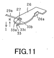
- the retainer 33 Since the bend 33c of the retainer 33 makes an angle of ⁇ 1 with the direction of extension of the first arm 29a, the retainer 33 may be prohibited from being disengaged from the retention opening 27 of the retainer 33 even when the shutter member 15 has made opening/closure movement. That is, the torsion coil spring 29, the retainer 33 of which is bent at the distal end thereof, has the bend 33c extending along the lower surface of the coil spring mounting piece 26, as shown in Fig.11.
- the second arm 29b of the torsion coil spring 29 includes a second coil 31 c for having the torsion coil spring 29 rotationally engaged with the cartridge body member 5, as shown in Fig.10.
- This second coil 31 is wound a plural number of times in the opposite winding direction to that of the first coil 30 in a direction towards the one end 30a along the direction of thickness of the first coil 30.
- the second coil 31 is rotationally mounted to a support pin 42 protuberantly formed on the inner surface of the cartridge body member 5. While the wire diameter, number of turns or the free extending angle of the second coil 31 may be designed freely, as in the case of the first coil 30, such a torsion coil spring having optimum values of these parameter is desirably used.
- the thickness of the entire torsion coil spring 29 may be suppressed to reduce the size of the cartridge body member 5. That is, if, in a torsion coil spring having plural coils, the winding directions of the respective coils are the same, the second coil 31 is wound from the position of the opposite end 30b of the first coil 30 in the same direction as the first coil, that is, towards the opposite end 30b along the direction of thickness of the first coil 30.
- the thickness of the first coil 30 adds up to that of the second coil 31 c, resulting in the increased overall thickness of the spring and hence the increased thickness of the cartridge body unit in which to accommodate the torsion coil spring.
- the thickness of the disc drive device 50, for which the disc cartridge is inserted/ detached, is also increased.
- the second coil 31 is wound towards the one end 30a of the first coil 30 and hence the overall spring thickness can be suppressed to the thickness of the first coil 30 or to that of the second coil 31.
- the torsion coil spring 29 is provided towards the side of destination of movement of the shutter member 15 in the direction of opening the aperture for an optical head 13. That is, the torsion coil spring 29 is provided towards the upstream side of movement of the shutter member 15 from the position of closing the aperture for an optical head 13 to the position of opening the aperture.
- the upstream side of movement of the shutter member 15 is the direction of movement of the shutter member more and more away from the aperture for an optical head 13.
- the torsion coil spring 29 may be prevented from being protruded into the aperture for an optical head 13 when the aperture for an optical head 13 is opened, and hence the aperture for an optical head 13 may be opened wide apart.
- the upstream side of the movement of the shutter member 15 is the rear side corner thereof opposite to the end of insertion thereof into the disc drive device 50, and hence may be designed as a space with sufficient allowance, thus enabling the torsion coil spring 29 to be arranged efficaciously in the cartridge body member 5.
- the shutter member 15 When in the position of closing the aperture for an optical head 13, the shutter member 15 is biased by the torsion coil spring 29 along the direction indicated by arrow B in Fig.12 to keep the aperture for an optical head 13 closed.
- the shutter opening/closing member 63 provided to the disc drive device 50 and protruded into the transport passageway for the shutter member 15, is intruded into the guide groove 14, formed in the lateral surface 8 of the cartridge body member 5, so as to be abutted against the support piece 17 of the shutter member 15 from the downstream side along the direction of movement of the shutter member 15.
- the shutter opening/closing member 63 collides against the buffering part 20, formed on the support piece 17 of the shutter member 15, the shutter opening/closing member 63 may smoothly ride on the support piece 17 so as to be slid thereon, as the shutter opening/closing member 63 is flexed towards outside of the cartridge body member 5, as it is guided by the smoothly bent buffering part 20.
- the buffering part 20 is smoothly curved, the shock due to collision between the shutter opening/closing member 63 and the shutter member 15 may be absorbed and hence there is no catch by the end of the support piece 17 of the shutter member 15 to improve the sense of insertion of the disc cartridge into the disc drive device.
- deterioration or wear of colliding parts or generation of dust and dirt, otherwise caused by collision of the shutter opening/closing member 63 and the shutter member 15, may be prohibited from occurrence.
- the shutter opening/closing member 63 slid along the support piece 17, is intruded into the engagement opening 17a, formed at a mid part of the support piece 17, so as to be engaged with the shutter member 15.
- the shutter member 15 is also abutted by a shutter opening operating member, not shown, such that its movement relative to the cartridge body member 5 transported into the inside of the main body unit of the apparatus is regulated by the shutter opening/closing member 63 and by the shutter opening operating member. Hence, the shutter member is moved relative to the cartridge body unit, in the direction indicated by arrow A in Fig.1, to open the aperture for an optical head 13.
- the torsion coil spring 29 biases the shutter member 15 for movement along the direction of arrow A in Fig.13 to cause movement of the shutter member 15 in the direction of arrow A in Fig.13 for opening the aperture for an optical head 13 to maintain the shutter member 15 in the position of opening the aperture for an optical head 13.
- the first coil 30 at the mid part of the torsion coil spring 29 is also moved along the same direction as indicated by arrow B in Fig. 13.
- the biasing direction is reversed.
- the torsion coil spring 29 biases the shutter member 15 along the direction indicated by arrow B in Fig.12 to maintain the aperture for an optical head 13 in the closed position.
- the shutter member 15, thus biased by the torsion coil spring 29, is supported in each of the position closing the aperture for an optical head 13 and the position opening the aperture for an optical head 13, under the bias of the torsion coil spring 29, for positively maintaining the state of closing or opening the aperture for an optical head 13.
- the aperture for an optical head may reliably be opened or closed in association with insertion or ejection of the disc cartridge for the disc drive device 50.
- first and second positioning holes 43, 44 engaged by positioning pins provided to the disc drive device 50, as shown in Figs.2 and 3.
- the second positioning hole 44 is formed as an oblong hole, having the width-wise direction perpendicular to the movement direction of the shutter member 15 as a long diameter, for adjusting the engagement position of the positioning pin.
- engagement recesses 45, 46 engaged by parts of a cartridge loading mechanism provided to the disc drive device 50, on which is loaded the disc cartridge 1, as shown in Figs.1 and 2.
- the upper and lower cartridge halves 3, 4 are formed by e.g. injection molding of e.g. polycarbonate, and the optical disc 2 as well as the torsion coil spring 29, is housed in position.
- the upper and lower cartridge halves 3, 4 are then abutted and connected to each other and the shutter member 15 is then mounted in position.
- the lower cartridge half 4 is secured to a jig, not shown, and the support pin 42, mounted upright on the lower cartridge half 4, is rotationally introduced into the second coil 31 of the torsion coil spring 29.
- the upper cartridge half 3 is abutted against and ultrasonically welded to the lower cartridge half 4, whereby the support pin 42 is carried by a bearing part 41 provided to the upper cartridge half 3 and the torsion coil spring 29 is rotatably housed within the cartridge body member 5.
- the second coil 31 of the torsion coil spring 29 is rotatably carried by the support pin 42, so that the retainer 33 may now be protruded outwards via the lateral side 8 of the cartridge body member 5 formed with the slide guide part 18, as shown in Fig.14.
- the shutter member 15 is formed by punching and bending a thin metal sheet, or on molding a synthetic resin material, as described above. This shutter member 15 is mounted to the slide guide part 18, formed in the lateral side 8 of the cartridge body member 5, after the retainer 33 of the torsion coil spring 29, protruded from the lateral side 8 of the cartridge body member 5, is mounted in position to the coil spring mounting piece 26.
- the shutter part 16 of the shutter member 15 is extended along the shutter slide part 19, provided to the lower cartridge half 4, as the second engagement part 23 and the coil spring mounting piece 26, provided to the connecting part 21, are extended along a tapered surface 35a of a guide rail 35 provided to the upper cartridge half 3.
- the shutter member 15 is connected to the torsion coil spring 29 by the riser 33b of the retainer 33 of the torsion coil spring 29 being inserted via an open end of the retention opening 27 of the coil spring mounting piece 26 extended from the connecting part 21.
- the shutter member 15 is then slidably mounted to the cartridge body member 5, to complete the assembling of the disc cartridge 1, by engaging the first engagement part 22, extended from the connecting part 21 in the engagement groove 24 of the upper cartridge half 3 by the own resiliency, and by positioning the bent part 23a of the second engagement part 23 and the bent part 26a of the coil spring mounting piece 26 on the inner side of the guide rail 35, as shown in Fig.8
- the shutter member 15 may be mounted readily to the cartridge body member 5 by providing the retainer 33 of the torsion coil spring 29 with the riser 33b and by introducing the riser 33b into the retention opening 27, opened at one end, of the coil spring mounting piece 26, to provide for engagement between the torsion coil spring 29 and the shutter member 15. After the engagement is established, the extension 33a or the bend 33c provided to the retainer 33 of the torsion coil spring 29 is abutted against the coil spring mounting piece 26 to prohibit the torsion coil spring 29 and the shutter member 15 from becoming disengaged readily from each other.
- the disc cartridge 1 houses therein an optical disc 2 having recorded thereon program data or video data for running e.g. a television game.
- a disc drive device employing the disc cartridge 1, having housed therein the optical disc 2 according to the present invention, a disc drive device 50 including a disc drive device 51 and a display unit 52, as shown in Fig.15, is used.
- the disc drive device 51 is loaded with the disc cartridge 1 and has enclosed therein a disc drive unit for reproducing at least data recorded on the optical disc 2, and the display unit 52 is adapted for demonstrating picture data or letter/character data reproduced from the optical disc 2.
- a cartridge loading mechanism including a cartridge holder for loading the disc cartridge to the disc drive unit, although the cartridge loading mechanism is not shown.
- a cartridge insertion/ ejection opening 53 for introducing the disc cartridge 1 into the cartridge holder and for ejecting the disc cartridge 1 loaded on the cartridge holder.
- the cartridge insertion/ ejection opening 53 is formed as an opening just large enough to permit insertion/ ejection of the disc cartridge 1, and has a width W2 slightly larger than the width W1 of the disc cartridge 1 and a height H2 only slightly larger than the width W1 of the disc cartridge 1 introduced therein.
- the cartridge holder 54 is arranged facing the cartridge insertion/ ejection opening 53 in the main body unit of an apparatus 51.
- an ejection button 55 for ejecting the disc cartridge 1 held in the cartridge holder 54.
- buttons 56, 57 for actuating a control switch used in playing e.g. a television game.
- a control key 58 for scrolling an image demonstrated on the display unit 52 and a loudspeaker 59 for outputting audio signals reproduced from the optical disc 2.
- control buttons such as playback buttons, or a power supply switch actuating button, for controlling the disc drive unit, although these buttons are not shown.
- the display unit 52 is rotatably mounted, via a hinge unit 60, to the main body unit of an apparatus 51, on the back surface side of the main body unit of an apparatus 51, opposite to the front side surface provided with the cartridge inserting/ ejecting opening 53.
- the display unit 52 may be rotated towards the main body unit of an apparatus 51 so as to be superposed on the upper surface thereof, and is formed using a liquid crystal display panel.
- the disc cartridge 1 In loading the disc cartridge 1 on the disc drive device 50, the disc cartridge 1 is inserted via cartridge insertion/ ejection opening 53 into the main body unit of an apparatus 51, with the foremost side thereof carrying the arcuate section 7 as an inserting end, and is held by the cartridge holder 54, as shown in Fig.15.
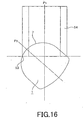
- the disc cartridge 1 since the inserting side of the disc cartridge of the present invention into the cartridge inserting/ ejecting opening 53 is formed as the approximately semicircular arcuate section 7, the disc cartridge 1 may smoothly be introduced into the cartridge inserting/ ejecting opening 53 and positively held by the cartridge holder 54, even in case a width-wise centerline P2 of the disc cartridge is appreciably tilted relative to a width-wise centerline P1 of the cartridge inserting/ejecting opening 53.
- the disc cartridge 1, having the inserting end formed as the substantially semicircular arcuate section 7, may be introduced into the main body unit of an apparatus 51 via the semicircular arcuate section 7, even in case the width-wise centerline P2 of the disc cartridge is inclined by up to approximately 45° towards left or right relative to the width-wise centerline P1 of the cartridge inserting/ ejecting opening 53, as shown in Figs.16 and 17.
- the disc cartridge 1 in the course of insertion into the cartridge inserting/ ejecting opening 53, the disc cartridge 1 is rotated, with the portion of the arcuate section 7 thereof, abutted against one or the other lateral side of the cartridge inserting/ ejecting opening 53, as the center of rotation, so that the centerlines P1, P2 will be brought into coincidence with each other, as shown in Fig.18, such as to readily correct the orientation of the disc cartridge.
- the disc cartridge 1 according to the present invention may positively be loaded in position on the cartridge holder 54 even in case of severe deviation of the direction of insertion thereof into the cartridge inserting/ ejecting opening 53.
- the shutter opening/closing member 63 With the disc cartridge 1, inserted into the cartridge holder 54, the shutter opening/closing member 63, arranged in the cartridge holder 54, is introduced into the disc cartridge via guide groove 14 in its lateral side 8 into abutment against the shutter member 15.
- the shutter member is flexed along the direction indicated by arrow D in Fig.5, by the inclined abutment surface 64a of the engagement part 64 abutting against the support piece 17 of the shutter member 15.
- the shutter opening/closing member 63 is engaged with the shutter member 15 by the engagement part 64 sliding along the support piece 17 so as to be intruded into the engagement opening 17a.
- the shutter opening/closing member 63 may be abutted against the buffering part 20 and guided by the moderately bent or tapered buffering part 20 so as to ride smoothly on the support piece 17. Consequently, the disc cartridge 1 may be inserted with a smooth sense of insertion into the disc drive device, with there being no catch due to collision between the end of the support piece 17 of the shutter member 15 and the shutter opening/closing member 63 of the disc drive device 50. In addition, deterioration or wear of colliding parts or generation of dust and dirt may be prohibited by absorbing the shock of collision between the shutter member 15 and the shutter opening/closing member 63.
- the shutter member 15 is abutted against a shutter opening member, not shown, and has its movement regulated by the shutter opening/closing member 63 and the shutter opening member, such that the shutter member 15 is moved relative to the cartridge body member 5, transported into the disc drive device 50, along the direction indicated by arrow A in Fig.1, thereby opening the aperture for an optical head 13.
- the cartridge body member 5 of the disc cartridge 1 is moved along the direction indicated by arrow E in Fig.18, in which the cartridge body member 5 opens the aperture for an optical head 13, the torsion coil spring 29 is biased, as shown in Fig.13 and 19.
- the biasing direction of the torsion coil spring 29 is reversed, such that the shutter member 15 is moved along the direction indicated by arrow F in Fig.18, which is the reverse of the movement direction of the cartridge body member 5, thereby opening the aperture for an optical head 13, as shown in Figs. 13 and 19 . Since the shutter member 15 is biased by the torsion coil spring 29 in the direction of opening the aperture for an optical head 13, the aperture for an optical head may positively be maintained in the opened state.
- an ejection button 55 is pressed. By actuating the ejection button 55, the operation for ejecting the disc cartridge 1, loaded on the cartridge loading unit, is carried out. When the ejecting operation is carried out, the disc cartridge 1 is transported towards the cartridge inserting/ ejecting opening 53.
- the cartridge body member 5 After the operation of closing the aperture for an optical head 13 and disengaging the shutter opening/closing member 63 from the shutter member 15, the cartridge body member 5 is ejected from the cartridge inserting/ ejecting opening 53 to complete the operation of ejecting the disc cartridge 1 loaded on the disc drive device 50.
- the present invention has been explained with reference to a disc cartridge having a semicircular shaped inserting end for reducing the cartridge size.
- the present invention is, however, not limited to the above-described disc cartridge and may directly be applied to a disc cartridge having a rectangular profile or to a disc cartridge having a recording and/or reproducing aperture on each of the upper and lower sides of the cartridge body unit with advantages similar to those of the above-described disc cartridge.
- the present invention may be broadly applied to a disc cartridge having a shutter member adapted for opening/closing a recording and/or reproducing aperture provided to the cartridge body unit.
Landscapes
- Feeding And Guiding Record Carriers (AREA)
Abstract
A disc cartridge includes a cartridge body unit having an optical disc (2) rotatably housed in it and provided with a recording and/or reproducing aperture (13) for exposing a part of the disc to outside, and a shutter member (15) slidably carried by the cartridge body member (5). A shutter opening/closing member (63) provided to a disc drive device (50) slides on the shutter member. The shutter member also includes an engagement opening (17a) engaged by the shutter opening/closing member. The shutter member operates for opening/closing the recording and/or reproducing aperture. The shutter member includes a collision buffering part (20) for absorbing the shock of collision against the shutter opening/closing member.
Description
- This invention relates to a disc cartridge having housed therein a disc, such as an optical disc, used as an information recording medium.
- This application claims priority of
Japanese Patent Application No.2004-003445, filed in Japan on January 8, 2004 - Up to now, a disc cartridge, which has rotationally housed therein a disc, such as an optical disc, used as an information recording medium, and which is loaded on a recording and/or reproducing apparatus as the disc is housed therein, has been put to extensive use. This sort of the disc cartridge protects the disc-shaped recording medium by housing it in a cartridge body member, while enabling facilitated insertion/ detachment of the disc for a recording and/or reproducing apparatus.
- Since the disc cartridge is designed to enable the disc to be loaded on the recording and/or reproducing apparatus, as the disc remains housed in the cartridge body member, there is formed in the cartridge body member a recording and/or reproducing aperture for exposing a part of the disc to outside across the inner and outer rims of the disc. A head part for recording and/or reproduction, such as an optical pickup, mounted to the recording and/or reproducing apparatus, faces the disc via this recording and/or reproducing aperture, and scans the signal recording area of the disc to record and/or reproduce the information signals.
- Thus, the disc cartridge, having the disc housed therein, is provided with a shutter member for closing the recording and/or reproducing aperture. This shutter member includes a rectangular flat-plate shaped shutter part, having the dimension sufficient to close the recording and/or reproducing aperture, and a
support part 101 of a U-shaped cross-section, formed towards the proximal end of the shutter part. The shutter member has its support part introduced into a groove-shaped slide guide formed in the cartridge body unit, and hence the shutter member is slidable along a lateral surface of the cartridge body unit. In this manner, the shutter member may be slid so that its shutter part may open/close the recording and/or reproducing aperture. - The shutter member includes, in a side of the support part thereof facing a lateral side of the cartridge body unit, a shutter opening/closing opening into which is inserted a shutter opening/
closing member 100 adapted for opening/closing the shutter member. This shutter opening/closing member, introduced into the shutter opening/closing opening, is provided to a main apparatus body unit of the disc recording and/or reproducing apparatus, and is formed by, for example, an elastic spring, exhibiting the flexibility. Referring to Fig.20, the shutter opening/closing member 100 includes a substantially chevron-shaped retention part 102 protruded on the movement trajectory of the shutter member for holding the so intruded disc cartridge in order to watch the intrusion of the disc cartridge. As the cartridge body unit is transported, thisretention part 102 is abutted against the foremost part of thesupport part 101 of the shutter member to flex the shutter opening/closing member 100. Thus, the shutter opening/closing member rides on thesupport part 101 to be slid thereon for intrusion into and engagement with the shutter opening/closing opening. - In this manner, the shutter opening/closing opening is regulated in the movement thereof along the slide guide part provided to the cartridge body unit to inhibit intrusion of the shutter member into the main apparatus body unit. Hence, the shutter member is moved relative to the cartridge body unit of the disc cartridge transported further into the main apparatus body unit, thereby opening the recording and/or reproducing aperture. When the disc cartridge is moved in the direction of being ejected from the disc recording and/or reproducing apparatus, the shutter member, engaged by the shutter opening/
closing member 100 and thereby prohibited from being moved further, is moved relative to the cartridge body unit of the disc cartridge being transported to outside the main apparatus body unit, such as to close the recording and/or reproducing opening. When the cartridge body unit is ejected to outside the recording and/or reproducing apparatus, the shutter opening/closing member 100 is flexed to outside the cartridge body unit, due to the sliding of the shutter opening/closing opening, and hence the retention part is receded from the shutter opening/closing opening. - With the above-described state-of-the art disc cartridge, the foremost part of the
support part 101 of the shutter member, which is the contact point of the shutter opening/closing member 100 with the shutter member, is square-shaped, with the consequence that theretention part 102 is abutted against the distal end of thesupport part 101 to interfere with smooth insertion and worsen the sense of insertion of the disc cartridge. In addition, theretention part 102 of the shutter opening/closing member 100 and thesupport part 101 of the shutter member, colliding against each other, tend to deteriorate or cause wear of the two components, while dust and dirt also tend to be produced. - It is therefore an object of the present invention to provide a novel disc cartridge whereby the aforementioned problems of the conventional disc cartridge may be resolved.
- It is another object of the present invention to provide a novel disc cartridge whereby the sense of insertion operation thereof into the disc recording and/or reproducing apparatus may be improved.
- It is yet another object of the present invention to provide a novel disc cartridge whereby it is possible to protect the shutter member adapted for opening/closing the recording and/or reproducing aperture.
- The disc cartridge according to the present invention includes a disc, a cartridge body unit having the disc rotatably housed therein and including a recording and/or reproducing aperture for exposing a part of the disc to outside, and a shutter member slidably carried by the cartridge body unit, The shutter member includes a shutter opening/closing member provided to a recording and/or reproducing apparatus for sliding on the shutter member. The shutter member also includes an engagement opening engaged by the shutter opening/closing member. The shutter member operates for opening/closing the recording and/or reproducing aperture. The shutter member includes a collision buffering part for absorbing the shock of collision against the shutter opening/closing member.
- When the disc cartridge according to the present invention is inserted into the recording and/or reproducing apparatus, the shutter opening/closing member, provided to the recording and/or reproducing apparatus, is abutted against the collision buffering part and, by being guided by this collision buffering part, smoothly rides on the shutter member so as to be slid thereon. Consequently, there is no catch between the end of the shutter member and the shutter opening/closing member of the recording and/or reproducing apparatus, thereby improving the sense of an inserting operation into the recording and/or reproducing apparatus and also protecting the shutter member and the shutter opening/closing member.
- Other objects and specified advantages of the present invention will become more apparent from the following explanation of the preferred embodiments thereof especially when read in conjunction with the drawings.
-
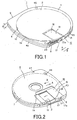
- Fig.1 is a perspective view of the disc cartridge of the present invention, looking from the upper cartridge half side.
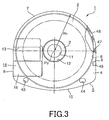
- Fig.2 is a perspective view of the disc cartridge of the present invention, looking from the lower cartridge half side.
- Fig.3 is a plan view of the disc cartridge of the present invention, looking from the lower cartridge half side.
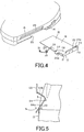
- Fig.4 is a perspective view showing the shutter member and the cartridge body unit carrying the shutter member.
- Fig.5 is a plan view showing the manner the shutter opening/closing member is abutted against the buffering part of the shutter member.
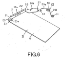
- Fig.6 is a perspective view showing the shutter member and a torsion coil spring mounted to this shutter member.
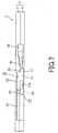
- Fig.7 is a side view showing the lateral side of the disc cartridge of the present invention carrying the shutter member.
- Fig.8 is a cross-sectional view showing the state of mounting the shutter member to the cartridge body unit.
- Fig.9 is a plan view showing another example of the shutter member of the disc cartridge embodying the present invention.
- Fig.10A is a plan view showing a torsion coil spring biasing the shutter member and Fig. 10B is a front view thereof.
- Fig.1 is a perspective view showing the torsion coil spring retained by the shutter member.
- Fig.12 is a plan view showing the disc cartridge with the aperture for a head being closed by the shutter member.
- Fig. 13 is a plan view showing the disc cartridge with the aperture for a head being opened by the shutter member.
- Fig.14 shows the manner of mounting the shutter member to the cartridge body unit.
- Fig.15 is a perspective view showing an example of a disc drive device employing a disc cartridge according to the present invention.
- Fig.16 is a plan view showing the state in which the disc cartridge is being introduced at an inclined state relative to the cartridge inserting/ ejection opening of the disc drive device.
- Fig.17 is a plan view showing the state in which the disc cartridge is being introduced in an inclined state in another direction relative to the cartridge inserting/ejection opening of the disc drive device.
- Fig.18 is a plan view showing the state the disc cartridge has been introduced with a controlled orientation into a cartridge holder.
- Fig.19 is a plan view showing the state the disc cartridge has been inserted into the cartridge holder, the shutter member is moved and the aperture for a head has been opened.
- Fig.20 is a plan view showing a shutter member of a conventional disc cartridge.
- Referring to the drawings, preferred embodiments of the present invention are explained in detail.
- A
disc cartridge 1 of the present embodiment has rotationally housed therein anoptical disc 2, as a disc used as an information recording medium. Referring to Figs.1 and 2, thedisc cartridge 1 includes acartridge body member 5, composed of paired upper andlower halves 3 and 4, abutted and connected together. Theoptical disc 2 is rotationally housed within thiscartridge body member 5. - The
disc cartridge 1 according to the present invention has housed therein theoptical disc 2, carrying video data or program data for playing a television game, and is formed to an extremely small size. Thisdisc cartridge 1 has housed therein a small-sizedoptical disc 2, with a diameter of approximately 60 mm, and is formed to a size that can be held in one's palm. - An upper cartridge half 3 and a
lower cartridge half 4, forming thecartridge body member 5 for housing theoptical disc 2, are formed by molding a synthetic resin material, and are abutted and connected to each other to form thecartridge body member 5. On the outer rims of the upper andlower cartridge halves 3, 4 are formed upstandingperipheral wall sections lower cartridge halves 3, 4 to each other to form adisc housing 6. Meanwhile, the upper andlower cartridge halves 3, 4 are coupled together by welding weld projections on the facing inner surfaces thereof by a welding technique, such as ultrasonic welding, to complete thecartridge body member 5. - The
cartridge body member 5, making up thedisc cartridge 1, has a forward surface, as an inserting end side of thedisc cartridge 1 into adisc drive device 50, in the form of anarcuate section 7, as shown in Figs.1 and 3. Thearcuate section 7 is formed to a substantially semi-circular shape, with a constant radius R1, having the center of theoptical disc 2, housed within thedisc housing 6 of thecartridge body member 5, as a center PO, as shown in Fig.2. That is, thearcuate section 7 is formed as a semi-circle facing a semi-circle of theoptical disc 2 housed within thecartridge body member 5. - The facing lateral surfaces of the
cartridge body member 5, continuing to thearcuate section 7 thereof, are formed as lateral sides parallel to each other, while the back surface thereof, lying on the opposite side of thearcuate section 7, is formed with a smoothly continuouslycurved section 10. - The
disc cartridge 1 according to the present invention has its front side, as an inserting end side, as the substantially semi-circulararcuate section 7, more strongly curved than the remaining surfaces, so that, when thedisc cartridge 1 is inserted or ejected by a slot-in system via a cartridge inserting/ ejecting opening, formed in the disc drive device, the direction of insertion of the disc cartridge into the device can be discerned readily. In particular, with thedisc cartridge 1 reduced in size so that it can be held in one's palm, the inserting direction can be discriminated with the feeling of the hand holding thedisc cartridge 1. In addition, thepresent disc cartridge 1 can be inserted into the disc drive device of the slot-in type not only extremely readily but highly reliably, as will be explained later. - Moreover, with the
disc cartridge 1, embodying the present invention, in which the inserting end side thereof is the substantially semi-circulararcuate section 7, with the back surface thereof, opposite to the arcuate section, being thecurved section 10, the disc cartridge may further be reduced in size as compared to theoptical disc 2 housed therein. - Centrally of the
lower cartridge half 4, forming the lower surface of thecartridge body member 5, there is formed a circular center opening 12 for exposing to outside acenter opening 11, formed in the center of theoptical disc 2, housed in thecartridge body member 5, and a neighboring area thereof, as shown in Figs.2 and 3. Into thecenter opening 12 is intruded a part of the disc rotating driving mechanism, provided to the disc drive device, adapted for loading thedisc cartridge 1 thereon, such as a turntable. - In the
lower cartridge half 4, forming the lower surface side of thecartridge body member 5, there is formed an aperture for anoptical head 13, as a recording and/or reproducing aperture, as shown in Figs.2 and 3. The aperture for anoptical head 13 is formed in onelateral surface 8 of thecartridge body member 5 to a rectangular shape and to a size sufficient to permit part of the signal recording area of theoptical disc 2 in thecartridge body member 5 to be exposed to outside across the inner and outer rims of the disc. That is, the aperture for anoptical head 13 is formed in thelateral side 8 which is the rectilinear planar surface other than the forward surface of thecartridge body member 5 in which has been formed thearcuate section 7. This aperture for anoptical head 13 is closed by ashutter member 15 which will be explained subsequently. - In the
lateral surface 8 of thecartridge body member 5, in which is opened one longitudinal end of the aperture for anoptical head 13, there is formed aguide groove 14, in which is guided a shutter opening member, as will be explained subsequently. When thedisc cartridge 1 is introduced into the disc drive device, the shutter opening member, formed on the disc drive device, is intruded into theguide groove 14 to abut the shutter opening member against theshutter member 15 to open the aperture for anoptical head 13. - The
shutter member 15 for opening/ closing the aperture for anoptical head 13 is formed by punching and bending a thin metal sheet or on molding the synthetic resin material. Theshutter member 15 includes a rectangular flat-plate-shapedshutter part 16, formed to a rectangular shape of a dimension large enough to close the aperture for anoptical head 13, and asupport piece 17 formed on the proximal end of theshutter part 16 to a U-shaped cross-section. - The
shutter member 15 supports the upper cartridge half 3 of thecartridge body member 5 by thesupport piece 17 so that the shutter member is carried for movement in the directions of arrows A and B in Fig.2 for opening/closing the aperture for anoptical head 13. That is, theshutter member 15 is mounted for movement to thecartridge body member 5, as thesupport piece 17 supports aslide guide part 18 formed by a fraction of the upstandingperipheral wall section 3 a of the upper cartridge half 3, as shown in Fig.4. Theshutter member 15 is slid in a direction of opening or closing the aperture for anoptical head 13, as thecartridge body member 5 is transported, by thesupport piece 17 engaging with a shutter opening/closingmember 63 provided to thedisc drive device 50. - The shutter opening/closing
member 63, engaged by theshutter member 15, is now explained. The shutter opening/closingmember 63 is engaged by theshutter member 15 to regulate the movement thereof to cause movement of theshutter member 15 relative to thecartridge body member 5 to close the aperture for anoptical head 13. The shutter opening/closingmember 63 is provided to acartridge holder 54 of thedisc drive device 50, as later explained, and is an elastic spring, exhibiting flexibility, as shown in Fig.5. The shutter opening/closingmember 63 is bent substantially to a chevron shape for protruding towards thecartridge body member 5, or is bent to form a chevron shaped cross-section, for defining anengagement part 64 adapted for engaging with theshutter member 15. - This
engagement part 64 is made up by aninclined abutment surface 64a, and aninclined thrust surface 64b. Theinclined abutment surface 64a is provided to the cartridge inserting/ ejectingopening 53 formed in thedisc drive device 50 and is abutted by theshutter member 15 of thedisc cartridge 1 transported into the inside of a main body unit of anapparatus 51. Theinclined thrust surface 64b is provided to a part of thedisc drive device 50 opposite to the cartridge inserting/ ejectingopening 53 and is thrust by theshutter member 15 of thedisc cartridge 1 being ejected to outside the main body unit of the apparatus. - This shutter opening/closing
member 63 watches thedisc cartridge 1 being transported, as theengagement part 64 thereof is protruded at all times into the movement trajectory of thecartridge body member 5. When thedisc cartridge 1 is inserted into thecartridge holder 54 of thedisc drive device 50 and transported to the loading position, theengagement part 64 is intruded into theguide groove 14 formed in thelateral surface 8 of thecartridge body member 5, and is flexed in a direction indicated by arrow D in Fig.5, by theinclined abutment surface 64a being abutted by thesupport piece 17 of theshutter member 15. The shutter opening/closingmember 63 is engaged with theshutter member 15, by theengagement part 64 sliding on thesupport piece 17, and intruding into anengagement opening 17a, as later explained. When thedisc cartridge 1 has been transported to outside thedisc drive device 50, theinclined thrust surface 64b of theengagement part 64 is thrust by theengagement opening 17a, so that the shutter opening/closingmember 63 becomes flexed in the direction indicated by arrow D in Fig.5. Theengagement part 64 is projected to outside theengagement opening 17a, so that the shutter opening/closingmember 63 is disengaged from theshutter member 15. - Referring to Figs.4 and 6, the
support piece 17 of theshutter member 15, engaged by the shutter opening/closingmember 63, is provided with a connectingpart 21, formed as one with and upright from the proximal end of theshutter part 16, and afirst engagement part 22 is formed by bending the foremost part of the connectingpart 21 towards theshutter part 16. On the downstream side of the connectingpart 21 along the direction of movement of theshutter member 15, there is formed asecond engagement part 23 by bending the connecting part in the form of an upper case letter L at a lower level than thefirst engagement part 22. The foremost portion of thesecond engagement part 23 is bent in the form of an upper case letter L towards thefirst engagement part 22 to form abent part 23a. - On the downstream side end of the
support piece 17, along the direction of movement of theshutter member 15, there is formed abuffering part 20 for absorbing the shock produced on abutment on the support piece by the shutter opening/closingmember 63 provided in thedisc drive device 50. Thebuffering part 20 is moderately bent so as to be curved from the end part of thesupport piece 17 towards the distal end of theshutter part 16. Hence, in inserting thedisc cartridge 1 into thedisc drive device 50, the shutter opening/closingmember 63, provided to the disc drive device, may be abutted against and guided by the moderatelybent buffering part 20 so as to ride smoothly on thesupport piece 17. Consequently, thedisc cartridge 1 may be inserted with a smooth sense of insertion into thedisc drive device 50, with there being no catch due to collision between the end of thesupport piece 17 of theshutter member 15 and the shutter opening/closingmember 63 of thedisc drive device 50. In addition, deterioration or wear of colliding parts or generation of dust and dirt may be prohibited by absorbing the shock of collision between theshutter member 15 and the shutter opening/closingmember 63. - In a mid portion of the
support piece 17 along the sliding direction of theshutter member 15, there is formed anengagement opening 17a engaged by the shutter opening/closingmember 63 at the time of insertion of the cartridge body member. Theengagement opening 17a provides for engagement between theshutter member 15 and the shutter opening/closingmember 63 by being engaged by the shutter opening/closingmember 63 which is slid along thesupport piece 17 as it is guided by thebuffering part 20. By theshutter member 15 engaging with the shutter opening/closingmember 63, the movement of theshutter member 15 is regulated, such that theshutter member 15 is moved relative to thecartridge body member 5 in a direction of closing the aperture for anoptical head 13. - Upstream of the movement direction of the
shutter member 15, the connectingpart 21 is provided with a coilspring mounting piece 26 having aretention opening 27 for engaging with and retaining atorsion coil spring 29 as later explained. Similarly to thesecond engagement part 23, the coilspring mounting piece 26 is formed with abent part 26a having the form of an upper case letter L, with the foremost part thereof protruding towards thefirst engagement part 22. - Into this
retention opening 27 is inserted and retained, from an opening end thereof, aretention part 33, provided to afirst arm section 29a of atorsion coil spring 29, as later explained, for interconnecting theshutter member 15 and thetorsion coil spring 29. - The
shutter member 15 is mounted on thecartridge body member 5 with theshutter part 16 extending over the aperture for anoptical head 13, as shown in Fig.2. At this time, thesupport piece 17 of theshutter member 15 is held sandwiched at the first andsecond engagement parts spring mounting piece 26, with thefirst engagement part 22 provided to thesupport piece 17 engaging in anengagement groove 24 formed in the lateral surface of theslide guide part 18, and with thebent parts second engagement part 23 and in the coilspring mounting piece 26, respectively, engaging with the foremost parts of theslide guide part 18, respectively, as shown in Figs.6, 7 and 8. Theshutter member 15, carried in this manner, is moved along the direction indicated by arrows A and B in Fig.2, for opening/closing the aperture for anoptical head 13, as the shutter member is guided by thesupport piece 17. - A recessed
shutter slide part 19 is formed in an area of thelower cartridge half 4 through which is moved theshutter part 16. Theshutter slide part 19 is formed to a depth such that theshutter part 16 is not protruded from the surface of thecartridge body member 5. - In a portion of the upstanding
peripheral wall section 4a of thelower cartridge half 4 of the present embodiment of thedisc cartridge 1, facing the aperture for anoptical head 13, there is formed a cut-out 25, as shown in Figs.4 and 8. That is, the aperture for anoptical head 13 is opened in an area extending across the inner and outer rims of thecartridge body member 5. - At least a portion of the
slide guide part 18 in the upper cartridge half 3, facing the aperture for anoptical head 13, is of a height H1, such that, when theoptical disc 2 in thedisc cartridge 1, loaded in position along the height-wise direction in a cartridge loading unit in thedisc drive device 50, has been loaded in position on the turntable, the slide guide part is not protruded from alower surface 2a of theoptical disc 2 facing thelower cartridge half 4, as shown in Fig.8. - With the
disc cartridge 1, constructed as described above, when theshutter member 15 is moved to open the aperture for anoptical head 13, the entire optical pickup, operating as a head for reading out information signals recorded on theoptical disc 2, may be positioned within thecartridge body member 5. In addition, when the optical pickup has been moved to a position in which the optical pickup scans the outer rim of the optical disc, the objective lens, condensing the laser beam scanning the signal recording area of theoptical disc 2, may be positioned within thecartridge body member 5, with the remaining optical block components being located outside thecartridge body member 5. - The result is that, with the disc cartridge according to the present invention, the optical pickup may be positioned across the inner and outer rims of the
cartridge body member 5, as the optical pickup is kept close to theoptical disc 2. Consequently, the signal recording area may be formed up to the outer rim of theoptical disc 2, thereby increasing the recording capacity of the optical disc. Moreover, since the optical pickup can be kept close to theoptical disc 2, the numerical aperture NA of the objective lens may be increased to reduce the beam spot of the laser beam condensed on the signal recording surface of theoptical disc 2, with the result that the information signals recorded on theoptical disc 2 may be increased in recording density. Additionally, since it is possible to increase the recording capacity as well as the recording density, theoptical disc 2 in need of a preset value of the recording capacity may be reduced in size. Since the optical pickup may be positioned across the inner and outer rims of thecartridge body member 5 to scan theoptical disc 2, it is possible to reduce the size of thecartridge body member 5 and hence also thedisc drive device 50 employing thiscartridge body member 5. - With the
disc cartridge 1 of the present invention, theshutter member 15, opening/closing the aperture for anoptical head 13, is mounted for movement along the planarlateral surface 8 of thecartridge body member 5, as shown in Figs. 1 and 2. Thus, theshutter member 15 is able to move rectilinearly with thesupport piece 17 lying along the planarlateral surface 8, thus assuring stable movement of the shutter member. - Since the aperture for an
optical head 13 is formed facing the planarlateral surface 8 of thecartridge body member 5, the portion of thelower cartridge half 4 carrying the cut-out 25 may also present a rectilinear surface. Thus, even though the cut-out 25 is formed and thelateral surface 8 facing the outside of thecartridge body member 5 is opened, the aperture for anoptical head 13 in its entirety may positively be closed by theshutter member 15, which is rectangular in profile and which is provided with therectilinear support piece 17 having a U-shaped cross-section. - The method for forming a buffering part of the
shutter member 15 in thedisc cartridge 1 according to the present invention is now explained. In the following explanation, the parts or components which are the same as those of thedisc cartridge 1 are depicted by the same reference numerals and the corresponding explanation is omitted for simplicity. - A
buffering part 40 is formed at the downstream side end along the movement direction of theshutter member 15 adapted for opening/closing the aperture for anoptical head 13 of thecartridge body member 5. Thebuffering part 40 is tapered by chamfering the end at an outer lateral side corner of thesupport piece 17, as shown in Fig.9. Hence, when thedisc cartridge 1 is introduced into thedisc drive device 50, the shutter opening/closingmember 63, provided to the disc drive device, may smoothly ride on thesupport piece 17, by being abutted against and guided along the taperedbuffering part 40. Consequently, thedisc cartridge 1 may be inserted with a smooth sense of insertion into thedisc drive device 50, with there being no catch due to collision between the end of thesupport piece 17 of theshutter member 15 and the shutter opening/closingmember 63 of thedisc drive device 50. In addition, deterioration or wear of colliding parts or generation of dust and dirt may be prohibited by buffering the collision between theshutter member 15 and the shutter opening/closingmember 63. - The
torsion coil spring 29 is now explained. Thistorsion coil spring 29 causes movement of theshutter member 15 in a direction of opening/closing the aperture for anoptical head 13, while holding theshutter member 15 in the position of opening or closing the aperture for anoptical head 13. Thetorsion coil spring 29 has its one end retained by theshutter member 15, while having its other end rotationally engaged with thecartridge body member 5. Thetorsion coil spring 29 rotationally biases theshutter member 15 in the direction of opening or closing the aperture for anoptical head 13 depending on the position of movement of theshutter member 15 relative to thecartridge body member 5. - Referring to Figs.10A and 10B, the
torsion coil spring 29 is made up by afirst arm 29a and asecond arm 29b on both sides of afirst coil 30 at a mid part thereof. The first andsecond arms shutter member 15 and are carried by a portion of thecartridge body member 5, respectively. - The
first coil 30 is formed to a preset thickness, by being wound several turns, with thefirst arm 29a and thesecond arm 29b extending from oneend 30a and theopposite end 30b along the direction of thickness thereof, respectively. While the wire diameter, number of turns or the free extending angle of thefirst coil 30 may be designed freely, such a torsion coil spring having optimum values of these parameter is most preferred. - The
first arm 29a, extended from thefirst coil 30, is provided at the distal end thereof with aretainer 33 adapted to be retained by theshutter member 15. Theretainer 33 is made up by anextension 33a, extended from the distal end of thefirst arm 29a, ariser 33b bent at substantially a right angle to the extending direction of theextension 33a, along the winding direction of thefirst coil 30, and abend 33c extending from the distal end of theriser 33b approximately parallel to thefirst arm 29a. The retainer is formed in its entirety substantially to a U-shape. Thebend 33c of theretainer 33 makes a preset angle θ1 with respect to the direction of extension of thefirst arm 29a. Thisretainer 33 has itsriser 33b introduced into theretention opening 27 bored in the distal end part of the coilspring mounting piece 26 of theshutter member 15, via an open end thereof, and is retained thereby to get thetorsion coil spring 29 carried by theshutter member 15. - Since the
bend 33c of theretainer 33 makes an angle of θ1 with the direction of extension of thefirst arm 29a, theretainer 33 may be prohibited from being disengaged from theretention opening 27 of theretainer 33 even when theshutter member 15 has made opening/closure movement. That is, thetorsion coil spring 29, theretainer 33 of which is bent at the distal end thereof, has thebend 33c extending along the lower surface of the coilspring mounting piece 26, as shown in Fig.11. Hence, even when thetorsion coil spring 29 is swung along the direction indicated by arrow H in Fig.11, or when theshutter member 15 is swung in the direction of arrow H in Fig.11, during the opening/closing movement of theshutter member 15, thebend 33c of theretainer 33 is abutted against the lower surface of the coilspring mounting piece 26 to prevent thetorsion coil spring 29 and theshutter member 15 from becoming disengaged from each other. - The
second arm 29b of thetorsion coil spring 29 includes a second coil 31 c for having thetorsion coil spring 29 rotationally engaged with thecartridge body member 5, as shown in Fig.10. Thissecond coil 31 is wound a plural number of times in the opposite winding direction to that of thefirst coil 30 in a direction towards the oneend 30a along the direction of thickness of thefirst coil 30. Thesecond coil 31 is rotationally mounted to asupport pin 42 protuberantly formed on the inner surface of thecartridge body member 5. While the wire diameter, number of turns or the free extending angle of thesecond coil 31 may be designed freely, as in the case of thefirst coil 30, such a torsion coil spring having optimum values of these parameter is desirably used. - Since the
first coil 30 and thesecond coil 31 of thetorsion coil spring 29 are wound a plural number of times in opposite directions to each other, the thickness of the entiretorsion coil spring 29 may be suppressed to reduce the size of thecartridge body member 5. That is, if, in a torsion coil spring having plural coils, the winding directions of the respective coils are the same, thesecond coil 31 is wound from the position of theopposite end 30b of thefirst coil 30 in the same direction as the first coil, that is, towards theopposite end 30b along the direction of thickness of thefirst coil 30. Thus, the thickness of thefirst coil 30 adds up to that of the second coil 31 c, resulting in the increased overall thickness of the spring and hence the increased thickness of the cartridge body unit in which to accommodate the torsion coil spring. The thickness of thedisc drive device 50, for which the disc cartridge is inserted/ detached, is also increased. - With the
torsion coil spring 29, in which thefirst coil 30 and the second coil 31c are opposite in the winding directions thereof, thesecond coil 31 is wound towards the oneend 30a of thefirst coil 30 and hence the overall spring thickness can be suppressed to the thickness of thefirst coil 30 or to that of thesecond coil 31. - Referring to Fig.12, the
torsion coil spring 29 is provided towards the side of destination of movement of theshutter member 15 in the direction of opening the aperture for anoptical head 13. That is, thetorsion coil spring 29 is provided towards the upstream side of movement of theshutter member 15 from the position of closing the aperture for anoptical head 13 to the position of opening the aperture. - Meanwhile, the upstream side of movement of the
shutter member 15 is the direction of movement of the shutter member more and more away from the aperture for anoptical head 13. Thus, by providing thetorsion coil spring 29 on this upstream side, thetorsion coil spring 29 may be prevented from being protruded into the aperture for anoptical head 13 when the aperture for anoptical head 13 is opened, and hence the aperture for anoptical head 13 may be opened wide apart. - In addition, in the
disc cartridge 1 of the present embodiment, the upstream side of the movement of theshutter member 15 is the rear side corner thereof opposite to the end of insertion thereof into thedisc drive device 50, and hence may be designed as a space with sufficient allowance, thus enabling thetorsion coil spring 29 to be arranged efficaciously in thecartridge body member 5. - When in the position of closing the aperture for an
optical head 13, theshutter member 15 is biased by thetorsion coil spring 29 along the direction indicated by arrow B in Fig.12 to keep the aperture for anoptical head 13 closed. When thedisc cartridge 1 is inserted into thedisc drive device 50 and loaded by the cartridge holder, the shutter opening/closingmember 63, provided to thedisc drive device 50 and protruded into the transport passageway for theshutter member 15, is intruded into theguide groove 14, formed in thelateral surface 8 of thecartridge body member 5, so as to be abutted against thesupport piece 17 of theshutter member 15 from the downstream side along the direction of movement of theshutter member 15. When the shutter opening/closingmember 63 collides against the bufferingpart 20, formed on thesupport piece 17 of theshutter member 15, the shutter opening/closingmember 63 may smoothly ride on thesupport piece 17 so as to be slid thereon, as the shutter opening/closingmember 63 is flexed towards outside of thecartridge body member 5, as it is guided by the smoothly bent bufferingpart 20. - Since the
buffering part 20 is smoothly curved, the shock due to collision between the shutter opening/closingmember 63 and theshutter member 15 may be absorbed and hence there is no catch by the end of thesupport piece 17 of theshutter member 15 to improve the sense of insertion of the disc cartridge into the disc drive device. In addition, deterioration or wear of colliding parts or generation of dust and dirt, otherwise caused by collision of the shutter opening/closingmember 63 and theshutter member 15, may be prohibited from occurrence. - The shutter opening/closing
member 63, slid along thesupport piece 17, is intruded into theengagement opening 17a, formed at a mid part of thesupport piece 17, so as to be engaged with theshutter member 15. Theshutter member 15 is also abutted by a shutter opening operating member, not shown, such that its movement relative to thecartridge body member 5 transported into the inside of the main body unit of the apparatus is regulated by the shutter opening/closingmember 63 and by the shutter opening operating member. Hence, the shutter member is moved relative to the cartridge body unit, in the direction indicated by arrow A in Fig.1, to open the aperture for anoptical head 13. - When the
shutter member 15 is moved relative to thecartridge body member 5 in the direction indicated by arrow A in Fig.1, the position of thefirst coil 30 of thetorsion coil spring 29, formed at a non-stationary center, is moved along the direction of arrow A along the direction of movement of theshutter member 15, with thesupport pin 42, about which is rotationally engaged thesecond coil 31, as the center of rotation. When thefirst coil 30 is further moved in the direction of arrow A until it has moved beyond the position of thesupport pin 42, the biasing direction of thetorsion coil spring 29 is inverted. When inverted in the biasing direction, thetorsion coil spring 29 biases theshutter member 15 for movement along the direction of arrow A in Fig.13 to cause movement of theshutter member 15 in the direction of arrow A in Fig.13 for opening the aperture for anoptical head 13 to maintain theshutter member 15 in the position of opening the aperture for anoptical head 13. - When the
disc cartridge 1, held in the position in which theshutter member 15 has opened the aperture for anoptical head 13, is taken to outside thedisc drive device 50, by way of performing the disc cartridge ejection operation, thecartridge body member 5 is transported to outside thedisc drive device 50. Theshutter member 15, the movement of which relative to thecartridge body member 5 is regulated by engagement by the shutter opening/closingmember 63, is moved relative to thecartridge body member 5, along the direction indicated by arrow B in Fig.13, by an operation which is the reverse of the operation of insertion already described. - When the
shutter member 15 is moved along the direction indicated by arrow B in Fig. 13, thefirst coil 30 at the mid part of thetorsion coil spring 29 is also moved along the same direction as indicated by arrow B in Fig. 13. When theshutter member 15 is moved further along the direction indicated by arrow B, and thefirst coil 30 has traveled beyond the position of thesupport pin 42, lying along the direction of movement of theshutter member 15, the biasing direction is reversed. When the biasing direction is reversed, thetorsion coil spring 29 biases theshutter member 15 along the direction indicated by arrow B in Fig.12 to maintain the aperture for anoptical head 13 in the closed position. - The
shutter member 15, thus biased by thetorsion coil spring 29, is supported in each of the position closing the aperture for anoptical head 13 and the position opening the aperture for anoptical head 13, under the bias of thetorsion coil spring 29, for positively maintaining the state of closing or opening the aperture for anoptical head 13. - On the other hand, since there is no necessity of providing the mechanism for holding the
shutter member 15 at the position of opening the aperture for anoptical head 13, against the bias of the biasing member, it is possible to simplify the mechanism of thedisc drive device 50 and to reduce the size of the apparatus. - Moreover, with the
disc cartridge 1, since theshutter member 15 is moved by thetorsion coil spring 29 in the direction of opening or closing the aperture for anoptical head 13, depending on the position of theshutter member 15 relative to the aperture for anoptical head 13 provided to thecartridge body member 5, the aperture for an optical head may reliably be opened or closed in association with insertion or ejection of the disc cartridge for thedisc drive device 50. - In addition, with the
present disc cartridge 1, since theshutter member 15 is biased by thetorsion coil spring 29 into movement towards the side of opening the aperture for anoptical head 13, there is no necessity of providing an overstroke for causing movement of opening the aperture for anoptical head 13, with the result that only a small area for movement for theshutter member 15 is sufficient, so that thedisc cartridge 1 itself may be reduced in size. - It is noted that, on both sides of the back surface of the
disc cartridge 1, formed as thecurved section 10, there are formed, in the lower surface of thecartridge body member 5, first and second positioning holes 43, 44, engaged by positioning pins provided to thedisc drive device 50, as shown in Figs.2 and 3. Thesecond positioning hole 44 is formed as an oblong hole, having the width-wise direction perpendicular to the movement direction of theshutter member 15 as a long diameter, for adjusting the engagement position of the positioning pin. - In opposite
lateral sides arcuate section 7 of thecartridge body member 5, there are formed engagement recesses 45, 46 engaged by parts of a cartridge loading mechanism provided to thedisc drive device 50, on which is loaded thedisc cartridge 1, as shown in Figs.1 and 2. - In addition, there is formed, in the opposite
lateral side 9 of thearcuate section 7 of thecartridge body member 5, there is formed anengagement recess 47 for ejection, engaged by a part of an ejection mechanism provided to thedisc drive device 50, as shown in Fig.2. - In the
lateral sides cartridge body member 5, there are formed discrimination holes or recesses for discriminating the sort of the optical disc, housed in the cartridge body unit, as necessary. - With the
disc cartridge 1, constructed as described above, the upper andlower cartridge halves 3, 4 are formed by e.g. injection molding of e.g. polycarbonate, and theoptical disc 2 as well as thetorsion coil spring 29, is housed in position. The upper andlower cartridge halves 3, 4 are then abutted and connected to each other and theshutter member 15 is then mounted in position. - Specifically, the
lower cartridge half 4 is secured to a jig, not shown, and thesupport pin 42, mounted upright on thelower cartridge half 4, is rotationally introduced into thesecond coil 31 of thetorsion coil spring 29. The upper cartridge half 3 is abutted against and ultrasonically welded to thelower cartridge half 4, whereby thesupport pin 42 is carried by a bearingpart 41 provided to the upper cartridge half 3 and thetorsion coil spring 29 is rotatably housed within thecartridge body member 5. At this time, thesecond coil 31 of thetorsion coil spring 29 is rotatably carried by thesupport pin 42, so that theretainer 33 may now be protruded outwards via thelateral side 8 of thecartridge body member 5 formed with theslide guide part 18, as shown in Fig.14. - The
shutter member 15 is formed by punching and bending a thin metal sheet, or on molding a synthetic resin material, as described above. Thisshutter member 15 is mounted to theslide guide part 18, formed in thelateral side 8 of thecartridge body member 5, after theretainer 33 of thetorsion coil spring 29, protruded from thelateral side 8 of thecartridge body member 5, is mounted in position to the coilspring mounting piece 26. - Specifically, the
shutter part 16 of theshutter member 15 is extended along theshutter slide part 19, provided to thelower cartridge half 4, as thesecond engagement part 23 and the coilspring mounting piece 26, provided to the connectingpart 21, are extended along atapered surface 35a of aguide rail 35 provided to the upper cartridge half 3. Theshutter member 15 is connected to thetorsion coil spring 29 by theriser 33b of theretainer 33 of thetorsion coil spring 29 being inserted via an open end of theretention opening 27 of the coilspring mounting piece 26 extended from the connectingpart 21. Theshutter member 15 is then slidably mounted to thecartridge body member 5, to complete the assembling of thedisc cartridge 1, by engaging thefirst engagement part 22, extended from the connectingpart 21 in theengagement groove 24 of the upper cartridge half 3 by the own resiliency, and by positioning thebent part 23a of thesecond engagement part 23 and thebent part 26a of the coilspring mounting piece 26 on the inner side of theguide rail 35, as shown in Fig.8 - The
shutter member 15 may be mounted readily to thecartridge body member 5 by providing theretainer 33 of thetorsion coil spring 29 with theriser 33b and by introducing theriser 33b into theretention opening 27, opened at one end, of the coilspring mounting piece 26, to provide for engagement between thetorsion coil spring 29 and theshutter member 15. After the engagement is established, theextension 33a or thebend 33c provided to theretainer 33 of thetorsion coil spring 29 is abutted against the coilspring mounting piece 26 to prohibit thetorsion coil spring 29 and theshutter member 15 from becoming disengaged readily from each other. - An example of a disc drive device for recording and/or reproducing information signals for the
optical disc 2, housed in thedisc cartridge 1, described above, is now explained. - The
disc cartridge 1 according to the present invention houses therein anoptical disc 2 having recorded thereon program data or video data for running e.g. a television game. Thus, as a disc drive device, employing thedisc cartridge 1, having housed therein theoptical disc 2 according to the present invention, adisc drive device 50 including adisc drive device 51 and adisplay unit 52, as shown in Fig.15, is used. Thedisc drive device 51 is loaded with thedisc cartridge 1 and has enclosed therein a disc drive unit for reproducing at least data recorded on theoptical disc 2, and thedisplay unit 52 is adapted for demonstrating picture data or letter/character data reproduced from theoptical disc 2. - In the
disc drive device 51 of thedisc drive device 50, having enclosed therein the disc drive unit, shown in Fig.15, there is provided a cartridge loading mechanism including a cartridge holder for loading the disc cartridge to the disc drive unit, although the cartridge loading mechanism is not shown. In the front surface of thedisc drive device 51, forming its one lateral side, there is formed a cartridge insertion/ ejection opening 53 for introducing thedisc cartridge 1 into the cartridge holder and for ejecting thedisc cartridge 1 loaded on the cartridge holder. The cartridge insertion/ ejection opening 53 is formed as an opening just large enough to permit insertion/ ejection of thedisc cartridge 1, and has a width W2 slightly larger than the width W1 of thedisc cartridge 1 and a height H2 only slightly larger than the width W1 of thedisc cartridge 1 introduced therein. Thecartridge holder 54 is arranged facing the cartridge insertion/ ejection opening 53 in the main body unit of anapparatus 51. - Towards one side of the front surface of the main body unit of an
apparatus 51, there is mounted anejection button 55 for ejecting thedisc cartridge 1 held in thecartridge holder 54. - Towards one side of the upper surface of the main body unit of an
apparatus 51, there are provided operatingbuttons apparatus 51, there are provided acontrol key 58 for scrolling an image demonstrated on thedisplay unit 52 and aloudspeaker 59 for outputting audio signals reproduced from theoptical disc 2. - On the main body unit of an
apparatus 51, there are mounted e.g. control buttons, such as playback buttons, or a power supply switch actuating button, for controlling the disc drive unit, although these buttons are not shown. - The
display unit 52 is rotatably mounted, via ahinge unit 60, to the main body unit of anapparatus 51, on the back surface side of the main body unit of anapparatus 51, opposite to the front side surface provided with the cartridge inserting/ ejectingopening 53. Thedisplay unit 52 may be rotated towards the main body unit of anapparatus 51 so as to be superposed on the upper surface thereof, and is formed using a liquid crystal display panel. - The state in which the
disc cartridge 1 according to the present invention is loaded on the above-describeddisc drive device 50 is now explained. - In loading the
disc cartridge 1 on thedisc drive device 50, thedisc cartridge 1 is inserted via cartridge insertion/ ejection opening 53 into the main body unit of anapparatus 51, with the foremost side thereof carrying thearcuate section 7 as an inserting end, and is held by thecartridge holder 54, as shown in Fig.15. - Meanwhile, since the inserting side of the disc cartridge of the present invention into the cartridge inserting/ ejecting
opening 53 is formed as the approximately semicirculararcuate section 7, thedisc cartridge 1 may smoothly be introduced into the cartridge inserting/ ejectingopening 53 and positively held by thecartridge holder 54, even in case a width-wise centerline P2 of the disc cartridge is appreciably tilted relative to a width-wise centerline P1 of the cartridge inserting/ejectingopening 53. - That is, the
disc cartridge 1, having the inserting end formed as the substantially semicirculararcuate section 7, may be introduced into the main body unit of anapparatus 51 via the semicirculararcuate section 7, even in case the width-wise centerline P2 of the disc cartridge is inclined by up to approximately 45° towards left or right relative to the width-wise centerline P1 of the cartridge inserting/ ejectingopening 53, as shown in Figs.16 and 17. In such case, in the course of insertion into the cartridge inserting/ ejectingopening 53, thedisc cartridge 1 is rotated, with the portion of thearcuate section 7 thereof, abutted against one or the other lateral side of the cartridge inserting/ ejectingopening 53, as the center of rotation, so that the centerlines P1, P2 will be brought into coincidence with each other, as shown in Fig.18, such as to readily correct the orientation of the disc cartridge. Thus, thedisc cartridge 1 according to the present invention may positively be loaded in position on thecartridge holder 54 even in case of severe deviation of the direction of insertion thereof into the cartridge inserting/ ejectingopening 53. - With the
disc cartridge 1, inserted into thecartridge holder 54, the shutter opening/closingmember 63, arranged in thecartridge holder 54, is introduced into the disc cartridge viaguide groove 14 in itslateral side 8 into abutment against theshutter member 15. The shutter member is flexed along the direction indicated by arrow D in Fig.5, by theinclined abutment surface 64a of theengagement part 64 abutting against thesupport piece 17 of theshutter member 15. The shutter opening/closingmember 63 is engaged with theshutter member 15 by theengagement part 64 sliding along thesupport piece 17 so as to be intruded into theengagement opening 17a. - At this time, the shutter opening/closing
member 63 may be abutted against the bufferingpart 20 and guided by the moderately bent or taperedbuffering part 20 so as to ride smoothly on thesupport piece 17. Consequently, thedisc cartridge 1 may be inserted with a smooth sense of insertion into the disc drive device, with there being no catch due to collision between the end of thesupport piece 17 of theshutter member 15 and the shutter opening/closingmember 63 of thedisc drive device 50. In addition, deterioration or wear of colliding parts or generation of dust and dirt may be prohibited by absorbing the shock of collision between theshutter member 15 and the shutter opening/closingmember 63. - The
shutter member 15 is abutted against a shutter opening member, not shown, and has its movement regulated by the shutter opening/closingmember 63 and the shutter opening member, such that theshutter member 15 is moved relative to thecartridge body member 5, transported into thedisc drive device 50, along the direction indicated by arrow A in Fig.1, thereby opening the aperture for anoptical head 13. - If, with the movement of the
shutter member 15 regulated, as described above, thecartridge body member 5 of thedisc cartridge 1 is moved along the direction indicated by arrow E in Fig.18, in which thecartridge body member 5 opens the aperture for anoptical head 13, thetorsion coil spring 29 is biased, as shown in Fig.13 and 19. If thetorsion coil spring 29 is biased such that thecartridge body member 5 is moved along the direction indicated by arrow E in Fig.18 and thefirst coil 30 has traveled past the position of thesupport pin 42, located to a downstream side along the direction of movement of theshutter member 15, the biasing direction of thetorsion coil spring 29 is reversed, such that theshutter member 15 is moved along the direction indicated by arrow F in Fig.18, which is the reverse of the movement direction of thecartridge body member 5, thereby opening the aperture for anoptical head 13, as shown in Figs. 13 and 19 . Since theshutter member 15 is biased by thetorsion coil spring 29 in the direction of opening the aperture for anoptical head 13, the aperture for an optical head may positively be maintained in the opened state. - The
disc cartridge 1, inserted into thecartridge holder 54, as the aperture for anoptical head 13 has been opened, is loaded in position on the cartridge loading unit provided in thedisc drive device 50. At this time, theoptical disc 2 is loaded in position on the disc drive device. The disc drive device is then actuated for reproducing program data recorded on the optical disc for running the program. - If, after reproducing the
optical disc 2, thedisc cartridge 1, loaded on thedisc drive device 50, is ejected, anejection button 55 is pressed. By actuating theejection button 55, the operation for ejecting thedisc cartridge 1, loaded on the cartridge loading unit, is carried out. When the ejecting operation is carried out, thedisc cartridge 1 is transported towards the cartridge inserting/ ejectingopening 53. - When the
disc cartridge 1 has been transported towards the cartridge inserting/ ejectingopening 53, theshutter member 15, the movement of which is regulated by the shutter opening/closingmember 63, is slid along the direction indicated by arrow B in Fig.1, relative to thecartridge body member 5, for closing the aperture for anoptical head 13. Theshutter member 15, slid along the direction indicated by arrow Bin Fig.1 relative to thecartridge body member 5, is biased along the direction indicated by arrow B by thetorsion coil spring 29, having the biasing direction reversed, for maintaining the closed state of the aperture for anoptical head 13. - When the
shutter member 15 has its sliding regulated by abutment against the end of theslide unit part 19 towards thearcuate section 7, theinclined thrust surface 64b of theengagement part 64 of the shutter opening/closingmember 63 is thrust by the end towards thearcuate section 7 of theengagement opening 17a, so that the shutter opening/closingmember 63 is flexed along the direction indicated by arrow D in Fig.5. Theengagement part 64 is ejected from theengagement opening 17a, whereby the shutter opening/closingmember 63 is disengaged from theshutter member 15. - After the operation of closing the aperture for an
optical head 13 and disengaging the shutter opening/closingmember 63 from theshutter member 15, thecartridge body member 5 is ejected from the cartridge inserting/ ejectingopening 53 to complete the operation of ejecting thedisc cartridge 1 loaded on thedisc drive device 50. - The present invention has been explained with reference to a disc cartridge having a semicircular shaped inserting end for reducing the cartridge size. The present invention is, however, not limited to the above-described disc cartridge and may directly be applied to a disc cartridge having a rectangular profile or to a disc cartridge having a recording and/or reproducing aperture on each of the upper and lower sides of the cartridge body unit with advantages similar to those of the above-described disc cartridge.
- In short, the present invention may be broadly applied to a disc cartridge having a shutter member adapted for opening/closing a recording and/or reproducing aperture provided to the cartridge body unit.
- The present invention is not limited to the above embodiments explained with reference to the drawings and may encompass various changes, substitutions or equivalents without departing from the scope of the invention as defined in the claims.
Claims (8)
- A disc cartridge comprising
a disc;
a cartridge body unit having said disc rotatably housed therein and including a recording and/or reproducing aperture for exposing a part of said disc to outside; and
a shutter member slidably carried by said cartridge body unit;
a shutter opening/closing member provided to a recording and/or reproducing apparatus sliding on said shutter member, said shutter member also including an engagement opening engaged by said shutter opening/closing member, said shutter member operating for opening/closing said recording and/or reproducing aperture;
said shutter member including a collision buffering part for absorbing the shock of collision against said shutter opening/closing member. - The disc cartridge according to claim 1 wherein said collision buffering part is a bend.
- The disc cartridge according to claim 1 wherein said collision buffering part is a chamfered part.
- The disc cartridge according to claim 1 wherein said collision buffering part is formed at a location struck by said shutter opening/closing member when the disc cartridge is loaded on said recording and/or reproducing apparatus.
- The disc cartridge according to claim 1 wherein said collision buffering part is formed at a downstream side end along the sliding direction of said shutter member when the shutter member is slid in the direction of opening said recording and/or reproducing aperture.
- The disc cartridge according to claim 5 wherein said engagement opening is formed on the more upstream side along the sliding direction of said shutter member than said collision buffering part.
- The disc cartridge according to claim 1 wherein an inserting end of said cartridge body unit into said recording and/or reproducing apparatus is arcuate-shaped.
- The disc cartridge according to claim 6 wherein, when the disc cartridge is loaded on said recording and/or reproducing apparatus, said shutter member begins sliding in the direction of opening said recording and/or reproducing aperture when said shutter opening/closing member collides against said collision buffering part so as to be then engaged with said engagement hole.
Applications Claiming Priority (2)
| Application Number | Priority Date | Filing Date | Title |
|---|---|---|---|
| JP2004003445A JP2005196900A (en) | 2004-01-08 | 2004-01-08 | Disc cartridge |
| PCT/JP2004/019008 WO2005066957A1 (en) | 2004-01-08 | 2004-12-20 | Disc cartridge |
Publications (2)
| Publication Number | Publication Date |
|---|---|
| EP1703510A1 true EP1703510A1 (en) | 2006-09-20 |
| EP1703510A4 EP1703510A4 (en) | 2008-10-29 |
Family
ID=34747078
Family Applications (1)
| Application Number | Title | Priority Date | Filing Date |
|---|---|---|---|
| EP04807365A Withdrawn EP1703510A4 (en) | 2004-01-08 | 2004-12-20 | DISC CARTRIDGE |
Country Status (7)
| Country | Link |
|---|---|
| US (1) | US7188351B2 (en) |
| EP (1) | EP1703510A4 (en) |
| JP (1) | JP2005196900A (en) |
| KR (1) | KR20060119703A (en) |
| CN (1) | CN1757072A (en) |
| TW (1) | TWI265487B (en) |
| WO (1) | WO2005066957A1 (en) |
Families Citing this family (3)
| Publication number | Priority date | Publication date | Assignee | Title |
|---|---|---|---|---|
| JP2005322288A (en) | 2004-05-07 | 2005-11-17 | Sony Corp | Disc recording and / or playback device |
| JP4168971B2 (en) | 2004-05-10 | 2008-10-22 | ソニー株式会社 | Disc recording and / or playback device |
| JP4281681B2 (en) * | 2004-12-10 | 2009-06-17 | ソニー株式会社 | Disc cartridge and shutter assembly method |
Family Cites Families (8)
| Publication number | Priority date | Publication date | Assignee | Title |
|---|---|---|---|---|
| JPH0739100Y2 (en) * | 1988-04-04 | 1995-09-06 | 日立マクセル株式会社 | Disk Cartridge |
| US5289457A (en) * | 1988-04-28 | 1994-02-22 | Dai Nippon Insatsu Kabushiki Kaisha | Disc cartridge with bent spring design for closing a closure shutter |
| JPH02110069U (en) * | 1989-02-13 | 1990-09-03 | ||
| JP3380928B2 (en) | 1994-03-31 | 2003-02-24 | ソニー株式会社 | Recording medium storage cartridge and method of manufacturing recording medium storage cartridge |
| US6542459B2 (en) * | 1998-05-28 | 2003-04-01 | Tdk Corporation | Cartridge and manufacturing method thereof |
| JP3515002B2 (en) | 1998-05-28 | 2004-04-05 | Tdk株式会社 | Cartridge and manufacturing method thereof |
| US6577592B1 (en) * | 1999-04-30 | 2003-06-10 | Sony Corporation | Disc cartridge |
| JP2002056601A (en) | 1999-11-12 | 2002-02-22 | Sony Corp | Disk cartridge device and disk cartridge |
-
2004
- 2004-01-08 JP JP2004003445A patent/JP2005196900A/en active Pending
- 2004-12-20 EP EP04807365A patent/EP1703510A4/en not_active Withdrawn
- 2004-12-20 KR KR1020057016681A patent/KR20060119703A/en not_active Ceased
- 2004-12-20 CN CNA200480006005XA patent/CN1757072A/en active Pending
- 2004-12-20 US US10/545,403 patent/US7188351B2/en not_active Expired - Fee Related
- 2004-12-20 WO PCT/JP2004/019008 patent/WO2005066957A1/en not_active Ceased
-
2005
- 2005-01-07 TW TW094100419A patent/TWI265487B/en not_active IP Right Cessation
Also Published As
| Publication number | Publication date |
|---|---|
| JP2005196900A (en) | 2005-07-21 |
| TWI265487B (en) | 2006-11-01 |
| KR20060119703A (en) | 2006-11-24 |
| US7188351B2 (en) | 2007-03-06 |
| EP1703510A4 (en) | 2008-10-29 |
| TW200535802A (en) | 2005-11-01 |
| CN1757072A (en) | 2006-04-05 |
| WO2005066957A1 (en) | 2005-07-21 |
| US20060080698A1 (en) | 2006-04-13 |
Similar Documents
| Publication | Publication Date | Title |
|---|---|---|
| US7188351B2 (en) | Disc cartridge | |
| US7555763B2 (en) | Disk cartridge | |
| CN100583280C (en) | Shutter device for disk cartridge, and disk recording and/or reproducing apparatus | |
| EP1699050B1 (en) | Disk cartridge, and recording and/or reproducing device | |
| US7526783B2 (en) | Disk cartridge | |
| JP4423943B2 (en) | Disc cartridge | |
| JP4423944B2 (en) | Disc cartridge | |
| US6871354B2 (en) | Disc cartridge, optical disk device, and method for information recording and reproducing | |
| JP4706185B2 (en) | Disc cartridge | |
| EP1650762B1 (en) | Disk cartridge, and disk recording and/or reproducing device | |
| CN1327441C (en) | Disk storage case and recording and/or reproducing device | |
| CN1327442C (en) | Disk cartridge | |
| JP2005259324A (en) | Disc cartridge and disc recording and / or reproducing apparatus | |
| JPH08106772A (en) | Shutter at cartridge insertion port | |
| JP2005063635A (en) | Disc cartridge | |
| JPH07130120A (en) | Shutter member, method for manufacturing the same, and disk cartridge using the shutter member |
Legal Events
| Date | Code | Title | Description |
|---|---|---|---|
| PUAI | Public reference made under article 153(3) epc to a published international application that has entered the european phase |
Free format text: ORIGINAL CODE: 0009012 |
|
| 17P | Request for examination filed |
Effective date: 20050812 |
|
| AK | Designated contracting states |
Kind code of ref document: A1 Designated state(s): AT DE FR GB |
|
| DAX | Request for extension of the european patent (deleted) | ||
| RBV | Designated contracting states (corrected) |
Designated state(s): AT DE FR GB |
|
| A4 | Supplementary search report drawn up and despatched |
Effective date: 20080925 |
|
| 17Q | First examination report despatched |
Effective date: 20090227 |
|
| STAA | Information on the status of an ep patent application or granted ep patent |
Free format text: STATUS: THE APPLICATION IS DEEMED TO BE WITHDRAWN |
|
| 18D | Application deemed to be withdrawn |
Effective date: 20100721 |