EP1703502A2 - Scanner for optical storage media - Google Patents
Scanner for optical storage media Download PDFInfo
- Publication number
- EP1703502A2 EP1703502A2 EP06300166A EP06300166A EP1703502A2 EP 1703502 A2 EP1703502 A2 EP 1703502A2 EP 06300166 A EP06300166 A EP 06300166A EP 06300166 A EP06300166 A EP 06300166A EP 1703502 A2 EP1703502 A2 EP 1703502A2
- Authority
- EP
- European Patent Office
- Prior art keywords
- scanner
- adhesive
- objective lens
- optical storage
- storage media
- Prior art date
- Legal status (The legal status is an assumption and is not a legal conclusion. Google has not performed a legal analysis and makes no representation as to the accuracy of the status listed.)
- Withdrawn
Links
- 230000003287 optical effect Effects 0.000 title claims abstract description 27
- 239000000853 adhesive Substances 0.000 claims abstract description 30
- 230000001070 adhesive effect Effects 0.000 claims abstract description 30
- 229920002379 silicone rubber Polymers 0.000 description 2
- 239000004945 silicone rubber Substances 0.000 description 2
- 239000011324 bead Substances 0.000 description 1
- 238000013016 damping Methods 0.000 description 1
- 239000000463 material Substances 0.000 description 1
- 239000011435 rock Substances 0.000 description 1
Images

Classifications
-
- A—HUMAN NECESSITIES
- A01—AGRICULTURE; FORESTRY; ANIMAL HUSBANDRY; HUNTING; TRAPPING; FISHING
- A01G—HORTICULTURE; CULTIVATION OF VEGETABLES, FLOWERS, RICE, FRUIT, VINES, HOPS OR SEAWEED; FORESTRY; WATERING
- A01G13/00—Protection of plants
- A01G13/30—Ground coverings
-
- G—PHYSICS
- G11—INFORMATION STORAGE
- G11B—INFORMATION STORAGE BASED ON RELATIVE MOVEMENT BETWEEN RECORD CARRIER AND TRANSDUCER
- G11B7/00—Recording or reproducing by optical means, e.g. recording using a thermal beam of optical radiation by modifying optical properties or the physical structure, reproducing using an optical beam at lower power by sensing optical properties; Record carriers therefor
- G11B7/12—Heads, e.g. forming of the optical beam spot or modulation of the optical beam
- G11B7/22—Apparatus or processes for the manufacture of optical heads, e.g. assembly
-
- G—PHYSICS
- G11—INFORMATION STORAGE
- G11B—INFORMATION STORAGE BASED ON RELATIVE MOVEMENT BETWEEN RECORD CARRIER AND TRANSDUCER
- G11B7/00—Recording or reproducing by optical means, e.g. recording using a thermal beam of optical radiation by modifying optical properties or the physical structure, reproducing using an optical beam at lower power by sensing optical properties; Record carriers therefor
- G11B7/12—Heads, e.g. forming of the optical beam spot or modulation of the optical beam
- G11B7/121—Protecting the head, e.g. against dust or impact with the record carrier
-
- G—PHYSICS
- G11—INFORMATION STORAGE
- G11B—INFORMATION STORAGE BASED ON RELATIVE MOVEMENT BETWEEN RECORD CARRIER AND TRANSDUCER
- G11B7/00—Recording or reproducing by optical means, e.g. recording using a thermal beam of optical radiation by modifying optical properties or the physical structure, reproducing using an optical beam at lower power by sensing optical properties; Record carriers therefor
- G11B7/12—Heads, e.g. forming of the optical beam spot or modulation of the optical beam
- G11B7/135—Means for guiding the beam from the source to the record carrier or from the record carrier to the detector
- G11B7/1372—Lenses
- G11B7/1374—Objective lenses
Definitions
- the present invention relates to a scanner for optical storage media, and to an appliance for reading from and/or writing to optical storage media which uses a scanner such as this.
- Scanners for optical storage media such as CDs (compact discs) or DVDs (digital versatile discs) normally use an actuator to control the spatial position of a scanning or writing beam.
- an actuator to control the spatial position of a scanning or writing beam.
- a control loop for the actuator is disturbed and the actuator collides with the storage medium in an uncontrolled manner.
- lens protection is frequently provided.
- One such means of lens protection is known, for example, from JP 2003-338063 .
- the lens protection is normally composed of a hard material. This has the disadvantage that it provides protection exclusively for the objective lens, and that the optical storage medium is still scratched. The scratches are produced radially, thus making further reading more difficult.
- One object of the invention is to propose an optical scanner in which damage to the optical storage medium and to the objective lens is prevented, and which can be produced easily.
- a scanner for optical storage media having an objective lens which is mounted in a lens holder by means of an adhesive, in which the adhesive is designed to provide protection for the objective lens.
- the objective lens is adhesively bonded to the lens holder.
- a small amount of excess adhesive protects the optical storage medium and the objective lens against being damaged in the event of collisions.
- no additional parts are required for protection of the objective lens, thus resulting in cost savings.
- the solution according to the invention reduces the mass of the actuator, thus making it possible to achieve faster scanning of an optical storage medium.
- the lens holder advantageously has adhesive pockets, which are adjacent to the objective lens, for holding the adhesive. This on the one hand results in reliable attachment of the objective lens, while on the other hand fixing the adhesive which is used for protection precisely in position.
- Optimum protection of the objective lens and of the optical storage medium is achieved by the adhesive projecting beyond the lens holder and the objective lens.
- the objective lens is preferably adhesively bonded to the lens holder by means of a soft adhesive.
- a soft adhesive damps the natural frequencies of the lens holder, so that the lens is decoupled from the natural frequencies of the lens holder.
- a scanner according to the invention is preferably used in an appliance for reading from and/or writing to optical storage media.
- Figure 1 shows a scanner 1 for optical storage media according to the prior art.
- the scanner 1 has a lens holder 2 for holding an objective lens 3, which is mounted in an opening in the lens holder 2.
- Three balls 4 composed of silicone rubber, which are pressed into associated cutouts 5 in the lens holder 2, act as protection against collisions between the objective lens 3 and an optical storage medium (not illustrated). Further elements of a scanner are known to those skilled in the art, and will not be explained any further here.
- FIG. 2 shows a scanner 1 according to the invention for optical storage media.
- an objective lens 3 is mounted in an opening in a lens holder 2.
- the mounting takes place by means of a soft adhesive, which is inserted into funnel-shaped adhesive pockets 6.
- the adhesive pockets 6 are designed such that they extend to the edge of the objective lens 3. If the adhesive pockets 6 are filled with a small amount of excess adhesive, then the projecting adhesive protects the optical storage medium and the objective lens 3 against being damaged by any collisions with the optical storage medium.
- a soft adhesive is World Rock No. 8799 from Kyoritsu Chemical Co., Ltd with a hardness of 70 Shore A.
- Two diagonal adhesion points are used in Figure 2. This is because the magnetic return paths of the actuator are arranged at the sides, so that there is insufficient space. If the space conditions are different, it is, however, likewise possible to use a greater number of adhesion points.
- One advantage of three or four adhesion points is that the objective lens 3 is held more reliably on all axes. However, this involves greater weight and additional costs. It is particularly advantageous to use three raised adhesion points as a compromise between weight, costs and reliability of the mounting. Furthermore, of course, it is possible for only some of the existing adhesion points to provide protection for the objective lens 3, for example two raised adhesion points of a total of four adhesion points. A circumferential adhesion bead is also possible.
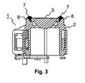
- Figure 3 shows a section illustration of the scanner 1.
- a section profile at 45 degrees has been chosen so that the adhesive pockets 6 can be seen. This illustrates well how the adhesive 7 in the adhesive pockets 6 projects beyond the lens holder 2 and the objective lens 3 in order to fit the objective lens 3, and is thus used for protection in the event of collisions.
- the objective lens 3 rests relatively loosely on the edge, but is not mechanically connected. This in itself results in a high degree of decoupling.
- the soft adhesive 7 acts as damping. Even better decoupling is achieved by attachment of the objective lens in such a way that it is does not rest thereon, but is held exclusively by the adhesive 7.
Landscapes
- Physics & Mathematics (AREA)
- Optics & Photonics (AREA)
- Health & Medical Sciences (AREA)
- General Health & Medical Sciences (AREA)
- Toxicology (AREA)
- Life Sciences & Earth Sciences (AREA)
- Environmental Sciences (AREA)
- Optical Head (AREA)
- Lenses (AREA)
- Lens Barrels (AREA)
Abstract
Description
- The present invention relates to a scanner for optical storage media, and to an appliance for reading from and/or writing to optical storage media which uses a scanner such as this.
- Scanners for optical storage media, such as CDs (compact discs) or DVDs (digital versatile discs) normally use an actuator to control the spatial position of a scanning or writing beam. During reproduction from or recording on optical storage media by such an optical scanner there is a risk that a control loop for the actuator is disturbed and the actuator collides with the storage medium in an uncontrolled manner. In order to prevent an objective lens which is attached to the actuator being damaged in a collision such as this, for example by being scratched, lens protection is frequently provided. One such means of lens protection is known, for example, from
JP 2003-338063 - The lens protection is normally composed of a hard material. This has the disadvantage that it provides protection exclusively for the objective lens, and that the optical storage medium is still scratched. The scratches are produced radially, thus making further reading more difficult.
-
US 2001/0019534 discloses objective lens stoppers in the form of balls composed of silicone rubber, which are pressed into associated cutouts in the actuator. This solution is illustrated in Figure 1, but has the disadvantage that additional parts must be used. - One object of the invention is to propose an optical scanner in which damage to the optical storage medium and to the objective lens is prevented, and which can be produced easily.
- According to the invention, this object is achieved by a scanner for optical storage media, having an objective lens which is mounted in a lens holder by means of an adhesive, in which the adhesive is designed to provide protection for the objective lens. The objective lens is adhesively bonded to the lens holder. A small amount of excess adhesive protects the optical storage medium and the objective lens against being damaged in the event of collisions. At the same time, no additional parts are required for protection of the objective lens, thus resulting in cost savings. Furthermore, the solution according to the invention reduces the mass of the actuator, thus making it possible to achieve faster scanning of an optical storage medium.
- The lens holder advantageously has adhesive pockets, which are adjacent to the objective lens, for holding the adhesive. This on the one hand results in reliable attachment of the objective lens, while on the other hand fixing the adhesive which is used for protection precisely in position.
- Optimum protection of the objective lens and of the optical storage medium is achieved by the adhesive projecting beyond the lens holder and the objective lens.
- The objective lens is preferably adhesively bonded to the lens holder by means of a soft adhesive. Although a hard adhesive may also be used, a soft adhesive damps the natural frequencies of the lens holder, so that the lens is decoupled from the natural frequencies of the lens holder.
- A scanner according to the invention is preferably used in an appliance for reading from and/or writing to optical storage media.
- In order to assist understanding, the invention will be explained with reference to Figures 1 to 3 in the following text. Identical reference symbols in this case denote identical elements. In the figures:
- Figure 1
- shows a scanner for optical storage media according to the prior art;
- Figure 2
- shows a scanner according to the invention for optical storage media; and
- Figure 3
- shows a section illustration of the scanner shown in Figure 2.
- Figure 1 shows a
scanner 1 for optical storage media according to the prior art. Thescanner 1 has alens holder 2 for holding anobjective lens 3, which is mounted in an opening in thelens holder 2. Threeballs 4 composed of silicone rubber, which are pressed into associatedcutouts 5 in thelens holder 2, act as protection against collisions between theobjective lens 3 and an optical storage medium (not illustrated). Further elements of a scanner are known to those skilled in the art, and will not be explained any further here. - Figure 2 shows a
scanner 1 according to the invention for optical storage media. In this case as well, anobjective lens 3 is mounted in an opening in alens holder 2. The mounting takes place by means of a soft adhesive, which is inserted into funnel-shapedadhesive pockets 6. Theadhesive pockets 6 are designed such that they extend to the edge of theobjective lens 3. If theadhesive pockets 6 are filled with a small amount of excess adhesive, then the projecting adhesive protects the optical storage medium and theobjective lens 3 against being damaged by any collisions with the optical storage medium. One example of a soft adhesive is World Rock No. 8799 from Kyoritsu Chemical Co., Ltd with a hardness of 70 Shore A. - Two diagonal adhesion points are used in Figure 2. This is because the magnetic return paths of the actuator are arranged at the sides, so that there is insufficient space. If the space conditions are different, it is, however, likewise possible to use a greater number of adhesion points. One advantage of three or four adhesion points is that the
objective lens 3 is held more reliably on all axes. However, this involves greater weight and additional costs. It is particularly advantageous to use three raised adhesion points as a compromise between weight, costs and reliability of the mounting. Furthermore, of course, it is possible for only some of the existing adhesion points to provide protection for theobjective lens 3, for example two raised adhesion points of a total of four adhesion points. A circumferential adhesion bead is also possible. - Figure 3 shows a section illustration of the
scanner 1. A section profile at 45 degrees has been chosen so that theadhesive pockets 6 can be seen. This illustrates well how the adhesive 7 in theadhesive pockets 6 projects beyond thelens holder 2 and theobjective lens 3 in order to fit theobjective lens 3, and is thus used for protection in the event of collisions. Theobjective lens 3 rests relatively loosely on the edge, but is not mechanically connected. This in itself results in a high degree of decoupling. Thesoft adhesive 7 acts as damping. Even better decoupling is achieved by attachment of the objective lens in such a way that it is does not rest thereon, but is held exclusively by the adhesive 7.
Claims (6)
- Scanner (1) for optical storage media, having an objective lens (3) which is mounted in a lens holder (2) by means of an adhesive (7), characterized in that the adhesive (7) is designed to provide protection for the objective lens (3).
- Scanner (1) according to Claim 1 with the lens holder having adhesive pockets (6), which are adjacent to the objective lens (3), for holding the adhesive (7).
- Scanner (1) according to Claim 1 or 2, with the adhesive (7) projecting beyond the lens holder (2) and the objective lens (3).
- Scanner (1) according to one of Claims 1 to 3, with the adhesive (7) being soft.
- Scanner (1) according to one of Claims 1 to 4, with the objective lens (3) being adhesively bonded to the lens holder (2) in such a way that it is decoupled from the natural frequencies of the lens holder (2).
- Appliance for reading from and/or writing to optical storage media, characterized in that the appliance has an optical scanner (1) according to one of Claims 1 to 5.
Applications Claiming Priority (1)
| Application Number | Priority Date | Filing Date | Title |
|---|---|---|---|
| DE102005013069A DE102005013069A1 (en) | 2005-03-18 | 2005-03-18 | Scanner for optical storage media |
Publications (2)
| Publication Number | Publication Date |
|---|---|
| EP1703502A2 true EP1703502A2 (en) | 2006-09-20 |
| EP1703502A3 EP1703502A3 (en) | 2007-04-18 |
Family
ID=36763756
Family Applications (1)
| Application Number | Title | Priority Date | Filing Date |
|---|---|---|---|
| EP06300166A Withdrawn EP1703502A3 (en) | 2005-03-18 | 2006-02-27 | Scanner for optical storage media |
Country Status (7)
| Country | Link |
|---|---|
| US (1) | US20060209639A1 (en) |
| EP (1) | EP1703502A3 (en) |
| JP (1) | JP2006260761A (en) |
| KR (1) | KR20060101289A (en) |
| CN (1) | CN1835097A (en) |
| DE (1) | DE102005013069A1 (en) |
| TW (1) | TW200641831A (en) |
Families Citing this family (4)
| Publication number | Priority date | Publication date | Assignee | Title |
|---|---|---|---|---|
| JP4850256B2 (en) * | 2006-11-29 | 2012-01-11 | 三菱電機株式会社 | Objective lens driving device and manufacturing method thereof |
| JP4378403B2 (en) * | 2007-09-13 | 2009-12-09 | キヤノン株式会社 | Optical pickup and optical disc apparatus |
| JP2011003252A (en) * | 2009-06-22 | 2011-01-06 | Hitachi Media Electoronics Co Ltd | Optical pickup device |
| CN103217225A (en) * | 2013-03-18 | 2013-07-24 | 中国科学院长春光学精密机械与物理研究所 | Supporting structure of point diffraction interferometer small hole plate |
Family Cites Families (6)
| Publication number | Priority date | Publication date | Assignee | Title |
|---|---|---|---|---|
| JPH07272302A (en) * | 1994-03-31 | 1995-10-20 | Matsushita Electric Ind Co Ltd | Objective lens device |
| US6327241B1 (en) * | 1997-04-08 | 2001-12-04 | Seagate Technology Llc | Optical data storage system with lens mount |
| JP3253558B2 (en) * | 1997-05-19 | 2002-02-04 | 株式会社三協精機製作所 | Objective lens drive |
| JP3986324B2 (en) * | 2002-02-22 | 2007-10-03 | アルパイン株式会社 | Bonding structure of objective lens and lens holder |
| JP4278364B2 (en) * | 2002-11-08 | 2009-06-10 | パイオニア株式会社 | Actuator for pickup device |
| JP3834816B2 (en) * | 2003-04-24 | 2006-10-18 | 船井電機株式会社 | Objective lens unit |
-
2005
- 2005-03-18 DE DE102005013069A patent/DE102005013069A1/en not_active Withdrawn
-
2006
- 2006-02-24 CN CNA2006100514123A patent/CN1835097A/en active Pending
- 2006-02-27 EP EP06300166A patent/EP1703502A3/en not_active Withdrawn
- 2006-03-03 TW TW095107090A patent/TW200641831A/en unknown
- 2006-03-14 KR KR1020060023581A patent/KR20060101289A/en not_active Withdrawn
- 2006-03-15 US US11/376,347 patent/US20060209639A1/en not_active Abandoned
- 2006-03-20 JP JP2006076508A patent/JP2006260761A/en not_active Withdrawn
Also Published As
| Publication number | Publication date |
|---|---|
| KR20060101289A (en) | 2006-09-22 |
| JP2006260761A (en) | 2006-09-28 |
| EP1703502A3 (en) | 2007-04-18 |
| CN1835097A (en) | 2006-09-20 |
| DE102005013069A1 (en) | 2006-09-28 |
| TW200641831A (en) | 2006-12-01 |
| US20060209639A1 (en) | 2006-09-21 |
Similar Documents
| Publication | Publication Date | Title |
|---|---|---|
| US6249432B1 (en) | Vibration dampening system for removable hard disk drive carriers | |
| US6961212B1 (en) | Shock isolation bearings and travel limit gaps in a spindle motor and disk drive using the same | |
| JP4880882B2 (en) | Disk drive mounting structure | |
| EP0929069A1 (en) | Suspension assembly | |
| JP2007505425A (en) | Disk drive unit mounting base, holding device, and disk drive unit mounting method | |
| US20060209639A1 (en) | Scanner for optical storage media | |
| US20080112125A1 (en) | Portable hard drive with axis specific shock absorption | |
| EP1542213A3 (en) | Optical pickup actuator | |
| US7404197B2 (en) | Disk drive | |
| JP4884479B2 (en) | Disk unit | |
| JP2005038538A (en) | Buffer component for external storage device | |
| JPWO2011121904A1 (en) | Magnetic disk unit | |
| JP4843350B2 (en) | Disk drive | |
| KR100585134B1 (en) | Disk holder and disk tray provided with the same | |
| US8495668B2 (en) | Spindle motor attachment structure for a disc drive apparatus | |
| CN101206880A (en) | CD drive | |
| JP2004239312A (en) | Buffer mechanism and recording and / or reproducing device | |
| KR20130014186A (en) | Pickup damper and disk drive having the same | |
| JP4445964B2 (en) | Recording medium driving device | |
| KR20070006413A (en) | Disk scratch protection | |
| US20130014134A1 (en) | Apparatus for clamping optical disc | |
| JPH0684275A (en) | Optical disk device protection cartridge | |
| JP2006236407A (en) | Optical disk device | |
| JP2009223973A (en) | Tool | |
| JP2009277318A (en) | Optical pickup |
Legal Events
| Date | Code | Title | Description |
|---|---|---|---|
| PUAI | Public reference made under article 153(3) epc to a published international application that has entered the european phase |
Free format text: ORIGINAL CODE: 0009012 |
|
| AK | Designated contracting states |
Kind code of ref document: A2 Designated state(s): AT BE BG CH CY CZ DE DK EE ES FI FR GB GR HU IE IS IT LI LT LU LV MC NL PL PT RO SE SI SK TR |
|
| AX | Request for extension of the european patent |
Extension state: AL BA HR MK YU |
|
| PUAL | Search report despatched |
Free format text: ORIGINAL CODE: 0009013 |
|
| AK | Designated contracting states |
Kind code of ref document: A3 Designated state(s): AT BE BG CH CY CZ DE DK EE ES FI FR GB GR HU IE IS IT LI LT LU LV MC NL PL PT RO SE SI SK TR |
|
| AX | Request for extension of the european patent |
Extension state: AL BA HR MK YU |
|
| AKX | Designation fees paid | ||
| STAA | Information on the status of an ep patent application or granted ep patent |
Free format text: STATUS: THE APPLICATION IS DEEMED TO BE WITHDRAWN |
|
| 18D | Application deemed to be withdrawn |
Effective date: 20071019 |
|
| REG | Reference to a national code |
Ref country code: DE Ref legal event code: 8566 |