EP1702685A1 - Fluid nozzle assemblies - Google Patents
Fluid nozzle assemblies Download PDFInfo
- Publication number
- EP1702685A1 EP1702685A1 EP05270005A EP05270005A EP1702685A1 EP 1702685 A1 EP1702685 A1 EP 1702685A1 EP 05270005 A EP05270005 A EP 05270005A EP 05270005 A EP05270005 A EP 05270005A EP 1702685 A1 EP1702685 A1 EP 1702685A1
- Authority
- EP
- European Patent Office
- Prior art keywords
- fluid
- nozzle
- outlet
- under pressure
- ducts
- Prior art date
- Legal status (The legal status is an assumption and is not a legal conclusion. Google has not performed a legal analysis and makes no representation as to the accuracy of the status listed.)
- Withdrawn
Links
- 239000012530 fluid Substances 0.000 title claims abstract description 97
- 238000000429 assembly Methods 0.000 title description 4
- 230000000712 assembly Effects 0.000 title description 4
- 230000000694 effects Effects 0.000 claims abstract description 17
- 239000003973 paint Substances 0.000 claims description 15
- 239000000203 mixture Substances 0.000 claims description 13
- XLYOFNOQVPJJNP-UHFFFAOYSA-N water Substances O XLYOFNOQVPJJNP-UHFFFAOYSA-N 0.000 claims description 12
- 238000000034 method Methods 0.000 claims description 7
- HSFWRNGVRCDJHI-UHFFFAOYSA-N alpha-acetylene Natural products C#C HSFWRNGVRCDJHI-UHFFFAOYSA-N 0.000 claims description 5
- QVGXLLKOCUKJST-UHFFFAOYSA-N atomic oxygen Chemical compound [O] QVGXLLKOCUKJST-UHFFFAOYSA-N 0.000 claims description 5
- 125000002534 ethynyl group Chemical group [H]C#C* 0.000 claims description 5
- 239000001301 oxygen Substances 0.000 claims description 5
- 229910052760 oxygen Inorganic materials 0.000 claims description 5
- 239000007789 gas Substances 0.000 claims description 4
- 125000006850 spacer group Chemical group 0.000 claims description 3
- 239000012159 carrier gas Substances 0.000 claims description 2
- 238000005520 cutting process Methods 0.000 abstract description 15
- 238000003466 welding Methods 0.000 abstract description 11
- 238000005507 spraying Methods 0.000 abstract description 9
- QFXZANXYUCUTQH-UHFFFAOYSA-N ethynol Chemical group OC#C QFXZANXYUCUTQH-UHFFFAOYSA-N 0.000 description 6
- 238000004140 cleaning Methods 0.000 description 5
- 238000005192 partition Methods 0.000 description 4
- 238000000576 coating method Methods 0.000 description 3
- 238000002474 experimental method Methods 0.000 description 3
- 238000004519 manufacturing process Methods 0.000 description 3
- 239000000463 material Substances 0.000 description 2
- 238000010422 painting Methods 0.000 description 2
- 239000011248 coating agent Substances 0.000 description 1
- 239000000470 constituent Substances 0.000 description 1
- 238000005260 corrosion Methods 0.000 description 1
- 239000002173 cutting fluid Substances 0.000 description 1
- 239000003599 detergent Substances 0.000 description 1
- 238000005530 etching Methods 0.000 description 1
- 238000012986 modification Methods 0.000 description 1
- 230000004048 modification Effects 0.000 description 1
- 238000007592 spray painting technique Methods 0.000 description 1
Images

Classifications
-
- B—PERFORMING OPERATIONS; TRANSPORTING
- B05—SPRAYING OR ATOMISING IN GENERAL; APPLYING FLUENT MATERIALS TO SURFACES, IN GENERAL
- B05B—SPRAYING APPARATUS; ATOMISING APPARATUS; NOZZLES
- B05B7/00—Spraying apparatus for discharge of liquids or other fluent materials from two or more sources, e.g. of liquid and air, of powder and gas
- B05B7/02—Spray pistols; Apparatus for discharge
- B05B7/06—Spray pistols; Apparatus for discharge with at least one outlet orifice surrounding another approximately in the same plane
-
- B—PERFORMING OPERATIONS; TRANSPORTING
- B05—SPRAYING OR ATOMISING IN GENERAL; APPLYING FLUENT MATERIALS TO SURFACES, IN GENERAL
- B05B—SPRAYING APPARATUS; ATOMISING APPARATUS; NOZZLES
- B05B7/00—Spraying apparatus for discharge of liquids or other fluent materials from two or more sources, e.g. of liquid and air, of powder and gas
- B05B7/02—Spray pistols; Apparatus for discharge
- B05B7/06—Spray pistols; Apparatus for discharge with at least one outlet orifice surrounding another approximately in the same plane
- B05B7/062—Spray pistols; Apparatus for discharge with at least one outlet orifice surrounding another approximately in the same plane with only one liquid outlet and at least one gas outlet
- B05B7/066—Spray pistols; Apparatus for discharge with at least one outlet orifice surrounding another approximately in the same plane with only one liquid outlet and at least one gas outlet with an inner liquid outlet surrounded by at least one annular gas outlet
-
- B—PERFORMING OPERATIONS; TRANSPORTING
- B05—SPRAYING OR ATOMISING IN GENERAL; APPLYING FLUENT MATERIALS TO SURFACES, IN GENERAL
- B05B—SPRAYING APPARATUS; ATOMISING APPARATUS; NOZZLES
- B05B7/00—Spraying apparatus for discharge of liquids or other fluent materials from two or more sources, e.g. of liquid and air, of powder and gas
- B05B7/02—Spray pistols; Apparatus for discharge
- B05B7/08—Spray pistols; Apparatus for discharge with separate outlet orifices, e.g. to form parallel jets, i.e. the axis of the jets being parallel, to form intersecting jets, i.e. the axis of the jets converging but not necessarily intersecting at a point
Definitions
- This invention is concerned with nozzle assemblies for use in directing fluids under high pressure and is especially though not exclusively concerned with such assemblies used in the industrial environment for the purposes of, for example, paint spraying, welding and cutting by the use of oxyacetylene, tools, plasma jet tools and the like, cutting by the use of super high pressure fluids, cleaning and like operations.
- each welding or cutting or painting tool is mounted on complex armature arrangements which enable the ultimate nozzle head to be manipulated to whatever position and attitude is required of it to carry out its appropriate function. Movement of each armature needs to be controlled to achieve this.
- a typical vehicle body part for example, needs to be shaped before it can be welded to other components, and the resultant structure cleaned at each stage as necessary.
- the welding and cleaning tools need to be computer controlled in order to ensure that the surfaces are properly prepared prior to entry into the paint stage.
- body parts are then required to be degreased, treated with anti-corrosion coating and then given final paint coatings, all of which require precise computer control of the various welding, cleaning, spraying and painting tools of a fully automated production line to achieve the desired result.
- high pressure fluid is also used as a cutting/etching medium and for removing unwanted coatings or other materials from surfaces, and in both such uses, a nozzle assembly is required to be physically moved in order to cut or clean as the case may be. In both instances, in the industrial environment, precise positioning of the nozzle assembly is again required and usually by computer controlled arrangements.
- the present invention seeks to simplify these systems by providing a nozzle assembly that itself can direct fluid in a desired direction thereby at least reducing the complexity of current fluid delivery systems.
- a fluid directing nozzle assembly comprising a nozzle head or member having an outlet through which a first fluid under pressure is directed in use, a sleeve surrounding said nozzle and defining therewith an annular conduit, spacer elements supporting the sleeve in spaced relationship to the nozzle outlet, and the conduit providing a plurality of separated ducts each having an outlet adjacent the outlet of the nozzle, each duct having a vane associated therewith, each vane being movably mounted on the sleeve and having a Coanda effect surface which is curved outwardly from the direction of said first fluid under pressure issuing from the nozzle outlet, the nozzle member being couplable to a source of said first under pressure and each duct being couplable to a, second, source of fluid under greater pressure than the fluid to be directed through the nozzle outlet.
- a nozzle assembly there may be as many or as few ducts as are required to control both the accuracy and the rate of delivery of fluid through the nozzle.
- all that is required of the nozzle assembly is that fluid is directed in one or other of the four possible orthogonal directions, which may be characterised as up, down, left and right, then only four ducts will be required.
- linear movement of the fluid as with a high pressure cutting tool, is all that is required, then it may be sufficient to provide a pair of opposed ducts that can be used to direct the fluid along a single linear path.
- Other arrangements of ducts can be determined depending upon the degree of accuracy required.
- Each vane is preferably pivotably mounted on the sleeve so that its influence can be varied to adjust the angle at which fluid can be directed from the nozzle.
- each vane is flexible and has a contour that can be varied to change the shape of its Coanda effect surface.
- the present invention further provides in another aspect, a system for directing fluid onto a surface, the system comprising a fluid directing nozzle assembly according to the present invention, a first source of fluid under pressure coupled to the nozzle outlet, a second source of fluid under pressure coupled to said plurality of separated ducts, the second source being arranged to deliver fluid through said ducts at a greater velocity than fluid delivered through the nozzle outlet whereby fluid directed through the ducts experiences a Coanda effect as it exits the ducts to control directing of fluid issuing from the nozzle outlet.
- the nozzle assembly may be adapted to deliver a gaseous fluid through the nozzle outlet, as in the case of the use of the nozzle assembly in for example an oxyacetylene cutting or welding system, where the gas is a mixture of oxygen and acetylene, and the system comprises means for controlling the relative amounts of oxygen and acetylene delivered to the nozzle outlet and the rate of delivery of one or both gases.
- a nozzle assembly according to the present invention may be used to direct a plasma jet for the purpose of cutting or welding.
- the nozzle assembly is adapted to deliver a mixture of paint and carrier gas or water under pressure.
- the nozzle assembly may be adapted to deliver water under pressure, and, in the case of a fluid cutting system wherein the cutting fluid, typically oil or water, may be delivered at pressures of 300MPa or greater. In the case of cleaning applications, the nozzle assembly may be adapted to deliver a mixture of water under pressure and a detergent fluid medium.
- the nozzle assembly is preferably mounted to be pivotable on a movable arm such that the nozzle assembly can be moved across a surface to be treated.
- the movement of any movable arm and of any vane would of course be computer controlled in an automated system.
- the provision of a nozzle assembly according to the present invention would allow for a wider range of coverage of a paint spraying from a single position of the nozzle assembly without the necessity of moving the nozzle assembly itself. Consequently, the mounting the nozzle assembly and therefore of the system can be simplified.
- the present invention further provides in another aspect, a method of delivering a, first, fluid under pressure at a target surface, the method comprising directing the, first, fluid under pressure at the target surface from an outlet nozzle and, as required, directing a second fluid from a second outlet closely adjacent said outlet nozzle alongside the first fluid under pressure, said second outlet being formed as a plurality of ducts around the outlet nozzle and having a vane providing a Coanda effect surface mounted on the outlet of each respective duct to deflect second fluid exiting through a duct away from direction of first fluid exiting from the outlet nozzle and thereby induce first fluid exiting from the outlet nozzle to be deflected in the same direction as the second fluid exiting from the duct, the second fluid, on exit from a duct, being at a greater velocity than the first fluid exiting from the nozzle outlet.
- the first fluid may, as stated above, be a gaseous fluid medium, such as an oxy-acetylene mixture or a plasma jet with the second fluid being air, or, in a second, paint spraying embodiment of the invention, the first fluid is a sprayable paint and the second fluid is air.
- a gaseous fluid medium such as an oxy-acetylene mixture or a plasma jet with the second fluid being air
- the first fluid is a sprayable paint and the second fluid is air.
- the nozzle assembly shown therein generally at 10 is specifically described hereinafter as suitable for use in paint spraying, as an example of directing a fluid medium which has two constituents. It may equally well be useful in principle, and with appropriate modifications to the design, dimensions and materials employed in manufacture of the nozzle assembly, for directing a mixture of gases, such as oxygen and acetylene, as would be used in an oxy-acetylene welding tool or an oxy-acetylene cutting tool.
- gases such as oxygen and acetylene
- the nozzle assembly 10 has a general axis of symmetry X - X and comprises a nozzle member 12 providing an outlet 14 through which fluidised paint under pressure can be pumped from a source thereof under pressure at a target surface when the spraying system of which the nozzle assembly forms a part is in use.
- the nozzle member is surrounded by a sleeve 16 and defines therewith an annular conduit 18.
- Spacer elements 20 ( Figure 3) support the sleeve in spaced relationship to the nozzle outlet, and sufficiently removed from the nozzle outlet 14 that they have no effect on the flow through the conduit 18.
- an, outer, housing 22 Surrounding the sleeve 16 is an, outer, housing 22 which is spaced from the sleeve by partition walls 24 ( Figure 3) which extend along the annular passage 26 defined between the sleeve 16 and the housing.
- the partition walls 24 extend the length of the housing and sleeve and divide the passage 26 into a plurality of separated ducts 28 each having an outlet 30 adjacent the outlet of the nozzle.
- four such ducts are shown though it will be appreciated that in practice and depending upon the intended function of the nozzle assembly, there may be as few as a pair of opposed ducts though for 360 degree control of direction, as described below, a minimum of three ducts is required.
- Each duct has a vane 32 associated therewith, each vane 32 being pivotably and movably mounted on the outer housing 22 and having a Coanda effect surface 34 which is curved outwardly from the direction of said first fluid under pressure issuing from the nozzle outlet 14.
- the vanes 32 are connected to and controlled by remote means (not shown) which can vary the angle of each vane relative to the direction of flow of fluid through the nozzle assembly. In of for an assembly plant or production line such as a white goods or vehicle assembly line, the remote means will be computer controlled.
- the nozzle assembly is couplable to a supply of a first component of the first fluid (e.g.
- paint to be delivered under pressure to the nozzle outlet 14 while the conduit 18 is couplable to a supply of a second component of the first fluid (e.g. air or water under pressure).
- the two components are admixed immediately downstream of the nozzle outlet 14 as is well known.
- the function of the ducts 28 is to permit air under pressure to flow therethrough to influence the direction of the fluid mixture emanating from the nozzle assembly. To this end, the supply of air through one or more of the ducts 28 is under greater pressure than the fluid mixture so that it exhausts from the or each duct 28 at a greater velocity then the fluid mixture from the nozzle assembly.
- gates 36 can be provided in the ducts 28, the position of the gates being remotely controllable between a first position in which the associated duct 28 is fully open and a second position in which the duct is fully closed. By adjusting the position of any gate, it is possible to control both the pressure and the rate of flow of the secondary flow.
- a supply of paint can be considered as being delivered via the nozzle outlet 14 and admixed with air under pressure delivered via the conduit 18. If then, a supply of air under pressure is coupled via the left hand duct 28, with the gate 36 fully open, that air supply, providing a secondary flow, is entrained by the Coanda effect to follow the curvature of the surface 34 of the associated vane 32 and is directed upwardly and to the left viewing Figure 1. The resultant pressure gradient caused by this deflection then causes the fluid mixture from the outlet 14 and conduit 18 also to be deflected in the same direction as the secondary fluid.
- the angle of deflection of the main fluid flow through the main outlet can be varied without moving the nozzle assembly.
- the quantity of paint delivered through the outlet 14 can also be varied by positioning a needle valve member 40 in the outlet 14, the needle valve member being of varying thickness so that it can be moved along the axis X - X to restrict the outlet 14.
- FIG 4 there is shown therein a nozzle assembly according to the present invention which is designed for directing a single fluid, such as water, under pressure.
- This assembly is similar to that of Figures 1 to 3 except that it excludes the conduit 18.
- water under pressure which for a water jet cutting tool may be a very high pressure
- a nozzle outlet 50 of a nozzle member 52 similar to outlet 14 of nozzle member 12 of Figure 1.
- the nozzle member 52 is coaxial with an outer housing 54 which is mounted in spaced relationship to the nozzle member 52 by a plurality of partitions (not shown) similar to the partitions 24 of the embodiment of Figure 1.
- a plurality of vanes 56 is mounted on the outlet end of the housing 54 and these are adjustable in the same manner as those described with reference to the embodiment of Figures 1 to 3, and will therefore not be further described.
- Each of the ducts is also provided with a gate 58 for varying and controlling flow of water/air as the case may be through that duct to control the direction of the primary fluid flow through the nozzle outlet 50.
Landscapes
- Nozzles (AREA)
Abstract
The invention relates to use of the Coanda effect in directing fluids such as may be used in cutting, spraying and welding tools, and so obviates the need for sophisticated complex mounting arrangements providing for 360 degree movement in three dimensions as are required by fully automated assembly plants. It achieves this by surrounding the outlet nozzle jet with two or more ducts (28) through which a secondary or auxiliary fluid can be delivered while the primary fluid is directed through the outlet nozzle jet. At the outlet end of each duct is provided a vane (32) that has a Coanda effect surface that can direct the flow of the secondary or auxiliary fluid around the surface and thereby direct the primary fluid in the same direction. Direction of the primary fluid can thereby be adjusted by varying the secondary fluid flow and by adjustment of the attitude of any vane (32).
Description
- This invention is concerned with nozzle assemblies for use in directing fluids under high pressure and is especially though not exclusively concerned with such assemblies used in the industrial environment for the purposes of, for example, paint spraying, welding and cutting by the use of oxyacetylene, tools, plasma jet tools and the like, cutting by the use of super high pressure fluids, cleaning and like operations.
- In modern automated systems such as may be used in assembly plants (e.g. vehicle, white goods and the like), the operations of welding, cutting and spray painting are commonly computer controlled on a totally automated assembly line. Each welding or cutting or painting tool is mounted on complex armature arrangements which enable the ultimate nozzle head to be manipulated to whatever position and attitude is required of it to carry out its appropriate function. Movement of each armature needs to be controlled to achieve this.
- A typical vehicle body part, for example, needs to be shaped before it can be welded to other components, and the resultant structure cleaned at each stage as necessary.
- At each stage of the assembly, the welding and cleaning tools need to be computer controlled in order to ensure that the surfaces are properly prepared prior to entry into the paint stage.
- Subsequent to assembly, body parts are then required to be degreased, treated with anti-corrosion coating and then given final paint coatings, all of which require precise computer control of the various welding, cleaning, spraying and painting tools of a fully automated production line to achieve the desired result.
- It is an object of the present invention to reduce the complexity of these systems.
- In addition, high pressure fluid is also used as a cutting/etching medium and for removing unwanted coatings or other materials from surfaces, and in both such uses, a nozzle assembly is required to be physically moved in order to cut or clean as the case may be. In both instances, in the industrial environment, precise positioning of the nozzle assembly is again required and usually by computer controlled arrangements.
- The present invention seeks to simplify these systems by providing a nozzle assembly that itself can direct fluid in a desired direction thereby at least reducing the complexity of current fluid delivery systems.
- The present invention provides in one aspect, a fluid directing nozzle assembly comprising a nozzle head or member having an outlet through which a first fluid under pressure is directed in use, a sleeve surrounding said nozzle and defining therewith an annular conduit, spacer elements supporting the sleeve in spaced relationship to the nozzle outlet, and the conduit providing a plurality of separated ducts each having an outlet adjacent the outlet of the nozzle, each duct having a vane associated therewith, each vane being movably mounted on the sleeve and having a Coanda effect surface which is curved outwardly from the direction of said first fluid under pressure issuing from the nozzle outlet, the nozzle member being couplable to a source of said first under pressure and each duct being couplable to a, second, source of fluid under greater pressure than the fluid to be directed through the nozzle outlet.
- In a nozzle assembly according to the present invention, there may be as many or as few ducts as are required to control both the accuracy and the rate of delivery of fluid through the nozzle. Thus, if all that is required of the nozzle assembly is that fluid is directed in one or other of the four possible orthogonal directions, which may be characterised as up, down, left and right, then only four ducts will be required. On the other hand, if linear movement of the fluid, as with a high pressure cutting tool, is all that is required, then it may be sufficient to provide a pair of opposed ducts that can be used to direct the fluid along a single linear path. Other arrangements of ducts can be determined depending upon the degree of accuracy required.
- Each vane is preferably pivotably mounted on the sleeve so that its influence can be varied to adjust the angle at which fluid can be directed from the nozzle. In a further embodiment of the invention, it is also foreseen that each vane is flexible and has a contour that can be varied to change the shape of its Coanda effect surface.
- The present invention further provides in another aspect, a system for directing fluid onto a surface, the system comprising a fluid directing nozzle assembly according to the present invention, a first source of fluid under pressure coupled to the nozzle outlet, a second source of fluid under pressure coupled to said plurality of separated ducts, the second source being arranged to deliver fluid through said ducts at a greater velocity than fluid delivered through the nozzle outlet whereby fluid directed through the ducts experiences a Coanda effect as it exits the ducts to control directing of fluid issuing from the nozzle outlet.
- The nozzle assembly may be adapted to deliver a gaseous fluid through the nozzle outlet, as in the case of the use of the nozzle assembly in for example an oxyacetylene cutting or welding system, where the gas is a mixture of oxygen and acetylene, and the system comprises means for controlling the relative amounts of oxygen and acetylene delivered to the nozzle outlet and the rate of delivery of one or both gases. As a further alternative, a nozzle assembly according to the present invention may be used to direct a plasma jet for the purpose of cutting or welding.
- Alternatively, the nozzle assembly is adapted to deliver a mixture of paint and carrier gas or water under pressure.
- Where the system is intended for use as a cleaning or fluid cutting system, the nozzle assembly may be adapted to deliver water under pressure, and, in the case of a fluid cutting system wherein the cutting fluid, typically oil or water, may be delivered at pressures of 300MPa or greater. In the case of cleaning applications, the nozzle assembly may be adapted to deliver a mixture of water under pressure and a detergent fluid medium.
- In a system according to the invention the nozzle assembly is preferably mounted to be pivotable on a movable arm such that the nozzle assembly can be moved across a surface to be treated. The movement of any movable arm and of any vane would of course be computer controlled in an automated system. However, the provision of a nozzle assembly according to the present invention would allow for a wider range of coverage of a paint spraying from a single position of the nozzle assembly without the necessity of moving the nozzle assembly itself. Consequently, the mounting the nozzle assembly and therefore of the system can be simplified.
- The present invention further provides in another aspect, a method of delivering a, first, fluid under pressure at a target surface, the method comprising directing the, first, fluid under pressure at the target surface from an outlet nozzle and, as required, directing a second fluid from a second outlet closely adjacent said outlet nozzle alongside the first fluid under pressure, said second outlet being formed as a plurality of ducts around the outlet nozzle and having a vane providing a Coanda effect surface mounted on the outlet of each respective duct to deflect second fluid exiting through a duct away from direction of first fluid exiting from the outlet nozzle and thereby induce first fluid exiting from the outlet nozzle to be deflected in the same direction as the second fluid exiting from the duct, the second fluid, on exit from a duct, being at a greater velocity than the first fluid exiting from the nozzle outlet.
- In carrying out a method according to one embodiment, the first fluid may, as stated above, be a gaseous fluid medium, such as an oxy-acetylene mixture or a plasma jet with the second fluid being air, or, in a second, paint spraying embodiment of the invention, the first fluid is a sprayable paint and the second fluid is air.
- There now follows a detailed description which is to be read with reference to the accompanying drawing of two embodiments of nozzle assemblies according to the present invention, for use in systems according to the present invention and for carrying out methods according to the present invention.
- In the accompanying drawings:
- Figure 1 is a diagrammatic exaggerated cross-section of a nozzle assembly which can be used for spraying a mixture of fluids (e.g. paint) onto a surface;
- Figure 2 is an end view of the nozzle assembly shown in Figure 1;
- Figure 3 is a cross-sectional view taken on the line A - A of Figure 1; and
- Figure 4 is a diagrammatic exaggerated illustration of a nozzle assembly which can be used for controlling the direction of water under pressure.
- Referring to Figure 1, the nozzle assembly shown therein generally at 10 is specifically described hereinafter as suitable for use in paint spraying, as an example of directing a fluid medium which has two constituents. It may equally well be useful in principle, and with appropriate modifications to the design, dimensions and materials employed in manufacture of the nozzle assembly, for directing a mixture of gases, such as oxygen and acetylene, as would be used in an oxy-acetylene welding tool or an oxy-acetylene cutting tool.
- The
nozzle assembly 10 has a general axis of symmetry X - X and comprises anozzle member 12 providing anoutlet 14 through which fluidised paint under pressure can be pumped from a source thereof under pressure at a target surface when the spraying system of which the nozzle assembly forms a part is in use. The nozzle member is surrounded by asleeve 16 and defines therewith anannular conduit 18. Spacer elements 20 (Figure 3) support the sleeve in spaced relationship to the nozzle outlet, and sufficiently removed from thenozzle outlet 14 that they have no effect on the flow through theconduit 18. Surrounding thesleeve 16 is an, outer,housing 22 which is spaced from the sleeve by partition walls 24 (Figure 3) which extend along the annular passage 26 defined between thesleeve 16 and the housing. Thepartition walls 24 extend the length of the housing and sleeve and divide the passage 26 into a plurality ofseparated ducts 28 each having anoutlet 30 adjacent the outlet of the nozzle. In the embodiment shown in Figures 1 to 3, four such ducts are shown though it will be appreciated that in practice and depending upon the intended function of the nozzle assembly, there may be as few as a pair of opposed ducts though for 360 degree control of direction, as described below, a minimum of three ducts is required. If greater control of direction is needed, then more than four ducts can be provided. Each duct has avane 32 associated therewith, eachvane 32 being pivotably and movably mounted on theouter housing 22 and having aCoanda effect surface 34 which is curved outwardly from the direction of said first fluid under pressure issuing from thenozzle outlet 14. Thevanes 32 are connected to and controlled by remote means (not shown) which can vary the angle of each vane relative to the direction of flow of fluid through the nozzle assembly. In of for an assembly plant or production line such as a white goods or vehicle assembly line, the remote means will be computer controlled. The nozzle assembly is couplable to a supply of a first component of the first fluid (e.g. paint) to be delivered under pressure to thenozzle outlet 14 while theconduit 18 is couplable to a supply of a second component of the first fluid (e.g. air or water under pressure). The two components are admixed immediately downstream of thenozzle outlet 14 as is well known. - The function of the
ducts 28 is to permit air under pressure to flow therethrough to influence the direction of the fluid mixture emanating from the nozzle assembly. To this end, the supply of air through one or more of theducts 28 is under greater pressure than the fluid mixture so that it exhausts from the or eachduct 28 at a greater velocity then the fluid mixture from the nozzle assembly. - We have found by experiment that it is possible to influence the direction of a primary fluid flow by generating a secondary flow of fluid between the primary fluid flow and a Coanda effect surface, where the secondary fluid flow is caused to have a higher velocity than that of the primary fluid flow.
- In all aspects of the present invention, we have also determined from experiment that a number of curvatures can be adopted for the Coanda surface but that an optimum curvature for the Coanda surface is that of a section of a logarithmic spiral, which has a polar equation given by

or by the cartesian co-ordinates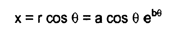

where r is the radius of the curve and a and b are constants. - In carrying out experiments, we have also determined that it is possible to effect a 30 degree vectoring of the primary fluid flow when the ratio of pressure of the secondary flow to that of the primary flow is between about 1.6 and 2.0.
- To control fluid flow through the ducts,
gates 36 can be provided in theducts 28, the position of the gates being remotely controllable between a first position in which the associatedduct 28 is fully open and a second position in which the duct is fully closed. By adjusting the position of any gate, it is possible to control both the pressure and the rate of flow of the secondary flow. - By way of explanation, and referring to Figure 1, a supply of paint can be considered as being delivered via the
nozzle outlet 14 and admixed with air under pressure delivered via theconduit 18. If then, a supply of air under pressure is coupled via theleft hand duct 28, with thegate 36 fully open, that air supply, providing a secondary flow, is entrained by the Coanda effect to follow the curvature of thesurface 34 of the associatedvane 32 and is directed upwardly and to the left viewing Figure 1. The resultant pressure gradient caused by this deflection then causes the fluid mixture from theoutlet 14 andconduit 18 also to be deflected in the same direction as the secondary fluid. - By varying the pressure of the air delivered via the
duct 28, the angle of deflection of the main fluid flow through the main outlet can be varied without moving the nozzle assembly. In consequence, it is possible to employ a nozzle assembly according to the present invention for spraying curved surfaces where previously it would have been necessary to physically move the nozzle assembly. - The quantity of paint delivered through the
outlet 14 can also be varied by positioning aneedle valve member 40 in theoutlet 14, the needle valve member being of varying thickness so that it can be moved along the axis X - X to restrict theoutlet 14. - Where a nozzle assembly similar to that described with reference to Figures 1 to 3 is used as the cutting or welding tip of an oxyacetylene tool or a plasma jet, it will be appreciated that the position of the cutting or welding tip of the flame or jet can be similarly varied by ducting air through one or other of the
ducts 28. - Referring now to Figure 4, there is shown therein a nozzle assembly according to the present invention which is designed for directing a single fluid, such as water, under pressure. This assembly is similar to that of Figures 1 to 3 except that it excludes the
conduit 18. - In carrying out a method according to the invention, water under pressure, which for a water jet cutting tool may be a very high pressure, is conventionally ejected through a
nozzle outlet 50 of anozzle member 52, similar tooutlet 14 ofnozzle member 12 of Figure 1. Thenozzle member 52 is coaxial with anouter housing 54 which is mounted in spaced relationship to thenozzle member 52 by a plurality of partitions (not shown) similar to thepartitions 24 of the embodiment of Figure 1. A plurality ofvanes 56 is mounted on the outlet end of thehousing 54 and these are adjustable in the same manner as those described with reference to the embodiment of Figures 1 to 3, and will therefore not be further described. Each of the ducts is also provided with agate 58 for varying and controlling flow of water/air as the case may be through that duct to control the direction of the primary fluid flow through thenozzle outlet 50.
Claims (10)
- A fluid directing nozzle assembly comprising a nozzle member having an outlet through which a first fluid under pressure is directed in use, a sleeve surrounding said nozzle and defining therewith an annular conduit, spacers elements supporting the sleeve in spaced relationship to the nozzle outlet, and the conduit providing a plurality of separated ducts each having an outlet adjacent the outlet of the nozzle, each duct having a vane associated therewith, each vane being movably mounted on the sleeve and having a Coanda effect surface which is curved outwardly from the direction of said first fluid under pressure issuing from the nozzle outlet, the nozzle member being couplable to a source of said first under pressure and each duct being couplable to a, second, source of fluid under greater pressure than the fluid to be directed through the nozzle outlet.
- A nozzle assembly according to claim 1 wherein each vane is flexible and has a contour that can be varied to change the shape of its Coanda effect surface.
- A system for directing fluid onto a surface, the system comprising a fluid directing nozzle assembly according to claim 1 or claim 2, a first source of fluid under pressure coupled to the nozzle outlet, a second source of fluid under pressure coupled to said plurality of separated ducts, the second source being arranged to deliver fluid through said ducts at a greater velocity than fluid delivered through the nozzle outlet whereby fluid directed through the ducts experiences a Coanda effect as it exits the ducts to control directing of fluid issuing from the nozzle outlet.
- A system according to claim 3 wherein each vane is independently movable to vary the effect on fluid from the second source flowing over the Coanda effect surface and thereby vary the direction at which fluid issuing from the nozzle outlet can be directed.
- A system according to claim 3 or claim 4 wherein the fluid is a mixture of oxygen and acetylene, and the system comprises means for controlling the relative amounts of oxygen and acetylene delivered to the nozzle outlet and the rate of delivery of one or both gases.
- A system according to claim 3 or claim 4 wherein the nozzle assembly is adapted to deliver a mixture of paint and carrier gas under pressure.
- A system according to claim 3 or claim 4 wherein the nozzle assembly is adapted to deliver a mixture of paint and water under pressure.
- A system according to claim 3 or claim 4 wherein the nozzle assembly is adapted to deliver water under pressure.
- A system according to any one of claims 5 to 8 wherein the nozzle assembly is mounted to be pivotable on a movable arm such that the nozzle assembly can be moved across a surface to be treated.
- A method of delivering a, first, fluid under pressure at a target surface, the method comprising directing the, first, fluid under pressure at the target surface from an outlet nozzle and, as required, directing a second fluid from a second outlet closely adjacent said outlet nozzle alongside the first fluid under pressure, said second outlet being formed as a plurality of ducts around the outlet nozzle and having a vane providing a Coanda effect surface mounted on the outlet of each respective duct to deflect second fluid exiting through a duct away from direction of first fluid exiting from the outlet nozzle and thereby induce first fluid exiting from the outlet nozzle to be deflected in the same direction as the second fluid exiting from the duct, the second fluid, on exit from a duct, being at a greater velocity than the first fluid exiting from the nozzle outlet.
Priority Applications (1)
| Application Number | Priority Date | Filing Date | Title |
|---|---|---|---|
| EP05270005A EP1702685A1 (en) | 2005-03-17 | 2005-03-17 | Fluid nozzle assemblies |
Applications Claiming Priority (1)
| Application Number | Priority Date | Filing Date | Title |
|---|---|---|---|
| EP05270005A EP1702685A1 (en) | 2005-03-17 | 2005-03-17 | Fluid nozzle assemblies |
Publications (1)
| Publication Number | Publication Date |
|---|---|
| EP1702685A1 true EP1702685A1 (en) | 2006-09-20 |
Family
ID=34941859
Family Applications (1)
| Application Number | Title | Priority Date | Filing Date |
|---|---|---|---|
| EP05270005A Withdrawn EP1702685A1 (en) | 2005-03-17 | 2005-03-17 | Fluid nozzle assemblies |
Country Status (1)
| Country | Link |
|---|---|
| EP (1) | EP1702685A1 (en) |
Cited By (3)
| Publication number | Priority date | Publication date | Assignee | Title |
|---|---|---|---|---|
| WO2023158868A1 (en) * | 2022-02-21 | 2023-08-24 | Cold Jet, Llc | Method and apparatus for minimizing ice build up within blast nozzle and at exit |
| JP2024515551A (en) * | 2021-04-05 | 2024-04-10 | ザイノン・テクノロジーズ・エルエルシー | Method for non-contact cleaning of optical fiber connectors and endfaces - Patents.com |
| RU2844902C2 (en) * | 2022-02-21 | 2025-08-11 | Колд Джет, Ллк | Method and apparatus for minimizing ice formation within a blasting nozzles and at an outlet |
Citations (4)
| Publication number | Priority date | Publication date | Assignee | Title |
|---|---|---|---|---|
| US2613995A (en) * | 1944-04-24 | 1952-10-14 | Reinhold Charles | Spray gun for paints and other liquids |
| US2812636A (en) * | 1950-06-16 | 1957-11-12 | Snecma | Process and device for deflecting jets |
| DE2421401A1 (en) * | 1974-05-03 | 1975-11-13 | Benecke Gmbh J | Laying of continuous filaments - uses curved guide shells to deflect course of filaments and carrier stream |
| SU968296A1 (en) * | 1981-03-19 | 1982-10-23 | Харьковский Ордена Ленина Авиационный Институт Им.Н.Е.Жуковского | Apparatus for thermal breaking of rock by high-temperature gas jet |
-
2005
- 2005-03-17 EP EP05270005A patent/EP1702685A1/en not_active Withdrawn
Patent Citations (4)
| Publication number | Priority date | Publication date | Assignee | Title |
|---|---|---|---|---|
| US2613995A (en) * | 1944-04-24 | 1952-10-14 | Reinhold Charles | Spray gun for paints and other liquids |
| US2812636A (en) * | 1950-06-16 | 1957-11-12 | Snecma | Process and device for deflecting jets |
| DE2421401A1 (en) * | 1974-05-03 | 1975-11-13 | Benecke Gmbh J | Laying of continuous filaments - uses curved guide shells to deflect course of filaments and carrier stream |
| SU968296A1 (en) * | 1981-03-19 | 1982-10-23 | Харьковский Ордена Ленина Авиационный Институт Им.Н.Е.Жуковского | Apparatus for thermal breaking of rock by high-temperature gas jet |
Non-Patent Citations (1)
| Title |
|---|
| DATABASE WPI Section PQ Week 198335, Derwent World Patents Index; Class Q49, AN 1983-751682, XP002342991 * |
Cited By (4)
| Publication number | Priority date | Publication date | Assignee | Title |
|---|---|---|---|---|
| JP2024515551A (en) * | 2021-04-05 | 2024-04-10 | ザイノン・テクノロジーズ・エルエルシー | Method for non-contact cleaning of optical fiber connectors and endfaces - Patents.com |
| WO2023158868A1 (en) * | 2022-02-21 | 2023-08-24 | Cold Jet, Llc | Method and apparatus for minimizing ice build up within blast nozzle and at exit |
| TWI884422B (en) * | 2022-02-21 | 2025-05-21 | 美商冷卻噴射公司 | Method and apparatus for minimizing ice build up within blast nozzle and at exit |
| RU2844902C2 (en) * | 2022-02-21 | 2025-08-11 | Колд Джет, Ллк | Method and apparatus for minimizing ice formation within a blasting nozzles and at an outlet |
Similar Documents
| Publication | Publication Date | Title |
|---|---|---|
| EP1700638B1 (en) | Nozzle for cold spray and cold spray apparatus using the same | |
| US7563322B2 (en) | Method and apparatus for online flow control over the span of a high aspect ratio slot jet | |
| CN101024881B (en) | Nozzles for Laser Net Shaping | |
| US9089724B2 (en) | Mist generating apparatus | |
| JP3927287B2 (en) | Oxygen fuel burner | |
| EP0575669B1 (en) | Atomizers and nozzle inserts therefor | |
| US10610998B2 (en) | Slurry blasting assembly | |
| US11745195B2 (en) | Spray nozzle device for delivering a restorative coating through a hole in a case of a turbine engine | |
| EP0875705B1 (en) | Flow diffuser and valve | |
| US6978942B2 (en) | Shockwave injector nozzle | |
| CN110434767B (en) | Double-sided peening of BLISK airfoils | |
| EP0444767A2 (en) | An apparatus and method for atomising a liquid | |
| EP1998035B1 (en) | Fluidic vectoring for exhaust nozzle | |
| AU682925B2 (en) | Steam conditioning butterfly valve | |
| CN118023007A (en) | Force Balance Spray Nozzle Device | |
| JP6046730B2 (en) | Spraying device with curved passage | |
| CN106714976A (en) | Dust and gas ejection valve | |
| US9731305B2 (en) | Nozzle apparatus and method | |
| GB2167320A (en) | A spray control system | |
| US9839988B2 (en) | Blast processing device and blast processing method | |
| KR102475416B1 (en) | Apparatus and method for edge processing of substrate sheets | |
| US11624442B2 (en) | Push-down-to-open high recovery choke valves | |
| JPH07545U (en) | High pressure water jet nozzle cartridge | |
| US20240157382A1 (en) | Spray nozzle device for delivering a restorative coating through a hole in a case of a turbine engine | |
| US6155501A (en) | Colliding-jet nozzle and method of manufacturing same |
Legal Events
| Date | Code | Title | Description |
|---|---|---|---|
| PUAI | Public reference made under article 153(3) epc to a published international application that has entered the european phase |
Free format text: ORIGINAL CODE: 0009012 |
|
| AK | Designated contracting states |
Kind code of ref document: A1 Designated state(s): AT BE BG CH CY CZ DE DK EE ES FI FR GB GR HU IE IS IT LI LT LU MC NL PL PT RO SE SI SK TR |
|
| AX | Request for extension of the european patent |
Extension state: AL BA HR LV MK YU |
|
| AKX | Designation fees paid | ||
| REG | Reference to a national code |
Ref country code: DE Ref legal event code: 8566 |
|
| STAA | Information on the status of an ep patent application or granted ep patent |
Free format text: STATUS: THE APPLICATION IS DEEMED TO BE WITHDRAWN |
|
| 18D | Application deemed to be withdrawn |
Effective date: 20070321 |