EP1701769B1 - Shoe for deep-water-running exercise - Google Patents
Shoe for deep-water-running exercise Download PDFInfo
- Publication number
- EP1701769B1 EP1701769B1 EP04815943A EP04815943A EP1701769B1 EP 1701769 B1 EP1701769 B1 EP 1701769B1 EP 04815943 A EP04815943 A EP 04815943A EP 04815943 A EP04815943 A EP 04815943A EP 1701769 B1 EP1701769 B1 EP 1701769B1
- Authority
- EP
- European Patent Office
- Prior art keywords
- drag
- shoe
- foot
- generating elements
- foundation
- Prior art date
- Legal status (The legal status is an assumption and is not a legal conclusion. Google has not performed a legal analysis and makes no representation as to the accuracy of the status listed.)
- Expired - Lifetime
Links
- 230000033001 locomotion Effects 0.000 claims abstract description 35
- XLYOFNOQVPJJNP-UHFFFAOYSA-N water Substances O XLYOFNOQVPJJNP-UHFFFAOYSA-N 0.000 claims abstract description 33
- 210000002683 foot Anatomy 0.000 claims description 35
- 238000000034 method Methods 0.000 claims description 9
- 210000003423 ankle Anatomy 0.000 claims description 8
- 210000004744 fore-foot Anatomy 0.000 claims description 5
- 210000000474 heel Anatomy 0.000 claims description 3
- 210000000452 mid-foot Anatomy 0.000 claims description 3
- 230000000694 effects Effects 0.000 description 5
- 239000000463 material Substances 0.000 description 5
- 238000012549 training Methods 0.000 description 5
- 208000027418 Wounds and injury Diseases 0.000 description 4
- 230000008901 benefit Effects 0.000 description 4
- 230000006378 damage Effects 0.000 description 4
- 239000012530 fluid Substances 0.000 description 4
- 208000014674 injury Diseases 0.000 description 4
- 230000005021 gait Effects 0.000 description 3
- 210000002414 leg Anatomy 0.000 description 3
- 210000003371 toe Anatomy 0.000 description 3
- 230000007423 decrease Effects 0.000 description 2
- 230000003247 decreasing effect Effects 0.000 description 2
- 238000011160 research Methods 0.000 description 2
- 239000013589 supplement Substances 0.000 description 2
- ZAMOUSCENKQFHK-UHFFFAOYSA-N Chlorine atom Chemical compound [Cl] ZAMOUSCENKQFHK-UHFFFAOYSA-N 0.000 description 1
- 238000013459 approach Methods 0.000 description 1
- 210000000544 articulatio talocruralis Anatomy 0.000 description 1
- 230000005540 biological transmission Effects 0.000 description 1
- 230000037396 body weight Effects 0.000 description 1
- 238000006243 chemical reaction Methods 0.000 description 1
- 229910052801 chlorine Inorganic materials 0.000 description 1
- 239000000460 chlorine Substances 0.000 description 1
- 238000010276 construction Methods 0.000 description 1
- 238000006073 displacement reaction Methods 0.000 description 1
- 239000004744 fabric Substances 0.000 description 1
- 239000006260 foam Substances 0.000 description 1
- 210000004394 hip joint Anatomy 0.000 description 1
- 230000003155 kinesthetic effect Effects 0.000 description 1
- 210000003127 knee Anatomy 0.000 description 1
- 210000000629 knee joint Anatomy 0.000 description 1
- 230000003278 mimic effect Effects 0.000 description 1
- 238000012986 modification Methods 0.000 description 1
- 230000004048 modification Effects 0.000 description 1
- 210000002346 musculoskeletal system Anatomy 0.000 description 1
- 230000008447 perception Effects 0.000 description 1
- 230000002265 prevention Effects 0.000 description 1
- 230000003252 repetitive effect Effects 0.000 description 1
- 238000004088 simulation Methods 0.000 description 1
- 239000007787 solid Substances 0.000 description 1
- 239000000126 substance Substances 0.000 description 1
Images


Classifications
-
- A—HUMAN NECESSITIES
- A63—SPORTS; GAMES; AMUSEMENTS
- A63B—APPARATUS FOR PHYSICAL TRAINING, GYMNASTICS, SWIMMING, CLIMBING, OR FENCING; BALL GAMES; TRAINING EQUIPMENT
- A63B21/00—Exercising apparatus for developing or strengthening the muscles or joints of the body by working against a counterforce, with or without measuring devices
- A63B21/00058—Mechanical means for varying the resistance
- A63B21/00065—Mechanical means for varying the resistance by increasing or reducing the number of resistance units
-
- A—HUMAN NECESSITIES
- A43—FOOTWEAR
- A43B—CHARACTERISTIC FEATURES OF FOOTWEAR; PARTS OF FOOTWEAR
- A43B5/00—Footwear for sporting purposes
- A43B5/08—Bathing shoes ; Aquatic sports shoes
-
- A—HUMAN NECESSITIES
- A63—SPORTS; GAMES; AMUSEMENTS
- A63B—APPARATUS FOR PHYSICAL TRAINING, GYMNASTICS, SWIMMING, CLIMBING, OR FENCING; BALL GAMES; TRAINING EQUIPMENT
- A63B21/00—Exercising apparatus for developing or strengthening the muscles or joints of the body by working against a counterforce, with or without measuring devices
- A63B21/008—Exercising apparatus for developing or strengthening the muscles or joints of the body by working against a counterforce, with or without measuring devices using hydraulic or pneumatic force-resisters
- A63B21/0084—Exercising apparatus for developing or strengthening the muscles or joints of the body by working against a counterforce, with or without measuring devices using hydraulic or pneumatic force-resisters by moving the surrounding water
-
- A—HUMAN NECESSITIES
- A63—SPORTS; GAMES; AMUSEMENTS
- A63B—APPARATUS FOR PHYSICAL TRAINING, GYMNASTICS, SWIMMING, CLIMBING, OR FENCING; BALL GAMES; TRAINING EQUIPMENT
- A63B21/00—Exercising apparatus for developing or strengthening the muscles or joints of the body by working against a counterforce, with or without measuring devices
- A63B21/40—Interfaces with the user related to strength training; Details thereof
- A63B21/4001—Arrangements for attaching the exercising apparatus to the user's body, e.g. belts, shoes or gloves specially adapted therefor
- A63B21/4011—Arrangements for attaching the exercising apparatus to the user's body, e.g. belts, shoes or gloves specially adapted therefor to the lower limbs
- A63B21/4015—Arrangements for attaching the exercising apparatus to the user's body, e.g. belts, shoes or gloves specially adapted therefor to the lower limbs to the foot
-
- A—HUMAN NECESSITIES
- A63—SPORTS; GAMES; AMUSEMENTS
- A63B—APPARATUS FOR PHYSICAL TRAINING, GYMNASTICS, SWIMMING, CLIMBING, OR FENCING; BALL GAMES; TRAINING EQUIPMENT
- A63B21/00—Exercising apparatus for developing or strengthening the muscles or joints of the body by working against a counterforce, with or without measuring devices
- A63B21/40—Interfaces with the user related to strength training; Details thereof
- A63B21/4023—Interfaces with the user related to strength training; Details thereof the user operating the resistance directly, without additional interface
- A63B21/4025—Resistance devices worn on the user's body
Definitions
- This invention relates to an apparatus for wearing on a user's foot during the exercise known as deep water running (DWR) to simulate running on land.
- DWR deep water running
- Running has been described as "essentially a series of collisions with the ground,” and these collisions typically exhibit vertical ground reaction forces (VGRF) of 1.5 to 3 times the runner's body weight.
- VGRF vertical ground reaction forces
- a known method of decreasing the running impact forces and the negative effects of excessive mileage is to supplement a runner's training program with deep-water running (DWR) in a pool.
- This mode of training allows the runner to mimic the terrestrial running style in the pool while typically using a buoyancy device, e.g., AquaJogger®, to support the runner's weight.
- a buoyancy device e.g., AquaJogger®
- DWR training method decreases spinal and joint compressive loading, which decreases the likelihood of incurring running-related injuries.
- a rationale for deep-water running (DWR) is that it allows the runner to train with movements similar to that found on land without incurring the impact forces, which greatly reduces the repetitive loading of the musculoskeletal system.
- Rehabilitation after injury, rather than prevention, is the most common use of deep water running.
- US-A-4,813,668 discloses an aquatic exercise boot provided for interchangeable and comfortable use by men, women and children alike.
- the aquatic exercise boot permits a large range of movement and increased resistive forces, torque and torsion.
- the aquatic exercise boot serves as fluid resistors to water flow as the aquatic boot is moved through the water.
- the aquatic exercise boot can have an ankle assembly with an expansion joint and pivotable side fins, a leg assembly with a calf-engaging clam shell and an aquatic leg section, and a foot assembly with an aquatic foot section and a curved aquatic sole.
- CA-A-961,063 discloses shoes for walking on the surface of water as a sport or recreation. These are primarily of a foam plastic, streamlined, solid throughout pontoon for each foot of the wearer.
- the pontoons are provided with flexible fins which are wrapped around the sides and bottom of, and attached to, the pontoon. These fins open up to resist backward motion thereby providing traction, and close against the bottom and sides of the pontoon to reduce drag during the forward motion. Also, when the fins are closed, folds are formed at the bottom corners of the pontoon to provide additional stability.
- the present invention is directed to apparatus as set out in the accompanying claim 1. Preferred feature of the apparatus are set out in the subordinate claims 2 to 10.
- the present invention extends to a method as set out in the accompanying claim 11. A preferred aspect of the method is set out in the accompanying subordinate claim 12.
- a shoe is particularly designed for use in DWR exercise to enhance the effects of the accommodating resistance provided by the water when the foot is moving from the anterior (front) to the posterior (back) portion of the gait.
- the unique construction of the shoe in accordance with the invention allows the runner to maintain proper running technique throughout the normal range of motion and to benefit from enhanced resistance in the appropriate planes of motion and minimal drag when appropriate.
- shoe means any article that is attached to a user's foot and includes that commonly known as a sandal, or a sock, or other similar articles.
- the shoe according to the invention utilize the accommodating resistance properties of water by increasing or decreasing drag to maximize resistance in the appropriate planes of motion inherent in a running gait. Increased overall benefit to the runner and an improved "feel" of the DWR exercise are achieved. Applicants' research also suggests that wearing a shoe during DWR enhances kinesthetic perception and further helps the runner achieve a gait during DWR that is more similar to that of land-based running.
- enhanced resistance is achieved by attaching three small scoops to each side of the shoe at the forefoot, mid-foot, and heel areas of the shoe.
- the scoops create fluid drag, and the size, configuration, and placement of the scoops are important to the effective operation of the shoe in DWR.
- the scoops must be configured and placed such that they conform both to the characteristics of the shoe and to the user's foot.
- the scoops are generally placed on the sides of the shoe, and the front part of the side of a shoe generally tapers downward such that the sides are shorter in that part of the shoe. Accordingly, the height of the scoop in the forward part of the shoe is often limited.
- the characteristics of the users foot affect the size and placement of the scoops and the materials from which the scoops may made. In particular, the foot articulates at the ankle and the ball, which means that rigid scoops that will restrict that motion must be avoided.
- the size and placement of the scoops affects the stability of the shoe during the running motion. Instability of the shoe, in turn, is transmitted to the runner and has a significant impact on its feel and its ability to simulate running on land. In addition, instability of the shoe results in transmission of forces to the runner, which could affect the runner's hip, knee, and ankle joints.
- a DWR shoe has more than one scoop attached to each side of the shoe such that they are generally symmetrical with respect to a vertical plane passing through the longitudinal axis of the shoe.
- One objective in placing the scoops in a symmetrical fashion is to ensure that the forces arising from fluid drag on both sides of the shoe are approximately equal.
- This approach generally is more effective in simulating land running. While the main purpose of the invention is the simulation of land or treadmill running, it is within the contemplation of the invention to arrange the scoops in an asymmetrical fashion, for example, for rehabilitation.
- Applicants have found that placing a single scoop, or fin, on the shoe or a single scoop on each respective side of the shoe generates flutter in the shoe as it moves through the water. This flutter is substantially eliminated by the use of more than one scoop longitudinally arranged on the side of the shoe. Further, a shoe with a single scoop could lead to hyperextension of the runner's knee.
- the fins may be configured to create different amounts of drag, and applicants have found it generally advantageous for the scoop located nearest the back of the shoe to create the largest amount of drag.
- the use of the largest scoop at the rear of the shoe is advantageous because the rear part of the shoe is better able to accommodate a large scoop and also because that places the most drag at the runner's heel, which further assists in simulating the feel of land-based running.
- the shape and size of a scoop are primary factors affecting the drag it produces during the forward and aft movements. Because the foot does not move strictly linearly (see figure 1 ) the shape affects the drag applied to the shoe in a variety of directions. It will also be appreciated that the movement of a runner's foot is rather complex because in normal running the foot rotates as the toes come up during the forward motion and then rotates down during the rearward motion.
- the scoops are generally conical with the front surfaces of the scoops sloping toward the side of the shoe from the back to the front. This configuration reduces drag in the forward direction while providing desired drag in the aft direction.
- the scoops in the front of the shoe are smaller than those at the rear. This assists in reducing flutter it is believed by reducing the effects of twisting (torsion) forces on the front of the foot by scoops that are too wide.
- Configuring the scoops with tapered front surfaces also allows the water to flow around the rear scoop and engage the scoop in front of it with less turbulence. Further, this reduces the shadowing of a forward scoop by a rearward one. Thus, the majority of the drag is provided by the rearmost scoop, and the drag provided by the foremost scoop is the least.
- the scoops are located on the shoe in a lower position of the sidewall. This places the drag forces lower on the shoe to further assist in simulating the application of forces that arise during land running.
- An object of this invention is to provide a shoe that simulates land-based running.
- Another object of this invention is to provide a shoe for use in DWR exercising.
- a further object of this invention is to provide a shoe having several elements that create fluid arranged on a shoe for creating drag simulating land-based running.
- Figure 1 is a plot showing the typical motion of a foot during dry-land running on a treadmill
- Figure 2 is a plot showing typical motion of a foot during deep water running with the article of the invention.
- Figure 3 is a bottom perspective view of a DWR shoe according to the invention.
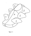
- Figure 4 is a top perspective view of the shoe shown in figure 3 .
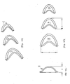
- FIGS 4a, 4b, and 4c illustrate preferred configurations and arrangements of the scoops.
- the present invention is a shoe, as defined above, for use in deep water running (DWR).
- Figure 1 illustrates the motion of the ankle of a runner when running on a treadmill.
- the curve 2 illustrates motion in a vertical plane when the runner is viewed from the right side, and the treadmill is moving from right to left: It will be appreciated that the bottom, somewhat linear portion, 4 of the graph represents movement of the foot when in contact with the treadmill.
- Figure 2 illustrates motion of the ankle of a runner wearing a shoe according to the invention. It will be appreciated that the curve 6 approximates the motion shown in figure 1 .
- the portion 8 of the graph 6 represents that part of the motion of the foot during which increased resistance is provided by the shoe of the invention.
- the foundation of the shoe preferably resembles a standard running shoe.
- the materials are selected for use in water, such as materials that are less susceptible to chemical attack from chlorine.
- the shoe may have a fabric upper and an elastomeric sole and may also be provided with one or more openings or the like to allow water to drain out of the shoe after use. Attached to the foundation along each side of the shoe are scoop-shaped protrusions. These protrusions are shaped to minimize hydrodynamic drag on the foot as it moves forward through the water. This shape also maximizes the drag as the runner moves his foot back though the water. Optimally the drag when moving in the backwards direction is 25%-30% greater than when moving in the forward direction.
- the scoop shape, size, material and position on the foundation are important to the performance of the device.
- the preferred embodiment of the invention uses three scoops per side, lined up in a row from the toe of the foundation to the heel.
- the scoop located nearest the heel is the largest of the three.
- the center scoop, located near the arch, is somewhat smaller.
- the scoop nearest the toe is the smallest.
- the scoop material is a semi-rigid plastic, which can be formed to the desired shape and affixed to the side of the foundation.
- FIGS 3 and 4 are perspective views of a shoe,2 according to the invention.
- a shoe foundation 10 may be formed in any of several shapes, a typical running shoe being illustrated. As noted above, however, the foundation may be in the form of a sock, a sandal, a boot, or the like. Preferably, however, the foundation is relatively small and light to provide the feel of a running shoe to simulate land running.
- the shoe according to the invention includes a plurality of scoops 12 attached to the sides of the shoe for the purpose of providing drag during the rearward movement of the shoe.
- Figures 4a, 4b, and 4c illustrate preferred scoops for use with a shoe of the invention.
- Figure 4a is a perspective view of three scoops 14, 16, and 18, which are preferably arranged in a line as shown on a shoe.
- Scoop 14 would be placed at the rear of the shoe and is the largest of the three scoops.
- Scoop 14 is preferably placed at the rear of the shoe and may be placed at the heel so that the rearmost part of the scoop 14 is flush with the rear of the shoe.
- This configuration allows the scoop to engage the water without the effects of turbulence created by the water flowing around the shoe before engaging the scoop.
- this scoop can be configured to provide the largest degree of drag.
- Scoop 16 is smaller that scoop 14 and scoop 18 is smaller than scoop 16.
- the scoops are attached to the sides of the shoe. This applies the drag forces to the side of the user's foot near the bottom of the shoe to simulate the forces applied by contact with the ground in land-based running.
- the scoops are preferably placed on the side of the shoe well below the ankle, and in some instances my actually extend onto the bottom (sole) of the shoe.
- Figure 4b is a side view of the scoops shown in figure 4a and figure 4c is an end view. These figures show some of the relevant dimensions of the scoops. Dimension "A” of figure 4c is the depth of a scoop, “B” is the height of a scoop, and “C” is the length of a scoop and “D” is the spacing between adjacent scoops.
- a shoe has 2 to 4 scoops arranged longitudinally on each side of a shoe, and preferably has three such scoops on each side. It is within the contemplation of the invention to provide a different number of scoops on each respective side, but in the preferred embodiment the scoops are symmetrical about a vertical plane.
- the depth of the scoops (“A") may be in the range of from about 6mm to about 40mm and more preferably in the range of from about 9mm to about 22mm.
- the height of the scoops (“B”) may be in the range of from about 19mm to about 75mm and more preferably from about 25mm to about 63mm.
- the lengths of the scoops may be in the range of from about 12mm to about 50mm and more preferably from about 18mm to about 45mm.
- the spacing of the scoops may be in the range of from about 50mm to about 75mm and preferably about 57mm.
- five scoops of generally arcuate cross section, tapered configuration are configured as set forth in the following table, and the three largest scoops are used for larger shoes (e.g., sizes 13, 14), the three smallest scoops are used for smaller shoes, and intermediate scoops are used with shoes of intermediate size.
- the difference in drag between a scoop and the adjacent scoop may be in the range of 10% to 20%.
- a typical running shoe without scoops provides about eleven percent more drag during rearward motion than in forward motion, when the average velocity of the foot is about 1.097 metres/second (3.6 ft./sec).
- the scoops of Table A attached to the sides of the shoe, the scoops produce 12% to 33% more drag in the rearward direction when the average velocity of about 1.097 metres/second (3.6 ft./sec).
- the scoops provide about 28% percent increased drag during rearward movement.
- scoops to provide the desired degree of increased drag as described above
- other elements may be provided with similar effect. It is not necessary to use a hollow "scoop" as such, and it may be possible to use other drag- creating elements, such as a flat or slightly curved paddle, or the like, that extends outward from the sides of the shoe.
- the front of such an element may include a fairing or similar structure to reduce the drag during forward motion of the foot.
- An advantage of a scoop is that it is conveniently attached to the shoe by stitching and may be conformed to the shape of other structures on the shoe whereby the same stitching is used for the scoop as well as for the other structures.
Landscapes
- Health & Medical Sciences (AREA)
- General Health & Medical Sciences (AREA)
- Physical Education & Sports Medicine (AREA)
- Life Sciences & Earth Sciences (AREA)
- Biophysics (AREA)
- Orthopedic Medicine & Surgery (AREA)
- Footwear And Its Accessory, Manufacturing Method And Apparatuses (AREA)
Abstract
Description
- This invention relates to an apparatus for wearing on a user's foot during the exercise known as deep water running (DWR) to simulate running on land.
- Approximately 30 million Americans participate in running as a form of general exercise for fitness and health. It has also been estimated that up to 70% of this population will incur a running-related injury. Running has been described as "essentially a series of collisions with the ground," and these collisions typically exhibit vertical ground reaction forces (VGRF) of 1.5 to 3 times the runner's body weight. These impact forces, as well as training errors resulting from increasing the total volume of mileage too rapidly and/or excessive mileage, are at least partially responsible for the creation of many running-related injuries.
- A known method of decreasing the running impact forces and the negative effects of excessive mileage is to supplement a runner's training program with deep-water running (DWR) in a pool. This mode of training allows the runner to mimic the terrestrial running style in the pool while typically using a buoyancy device, e.g., AquaJogger®, to support the runner's weight. It has been reported that the DWR training method decreases spinal and joint compressive loading, which decreases the likelihood of incurring running-related injuries. A rationale for deep-water running (DWR) is that it allows the runner to train with movements similar to that found on land without incurring the impact forces, which greatly reduces the repetitive loading of the musculoskeletal system. Rehabilitation after injury, rather than prevention, is the most common use of deep water running.
- Despite the increasing use of DWR for rehabilitation and more recently as training to supplement a normal regimen, very little research focuses on the DWR technique. Several sources describe "proper" DWR techniques, but it appears that the most common DWR style is characterized by a high-knee or piston-like leg action. In contrast, the cross-country style is intended to be more like land-based running. The specificity-of-training principle suggests that the movement pattern of DWR should be closely aligned with that of terrestrial running to maximize the benefit to the runner. The cross-country style of DWR is the one most like terrestrial running, particularly in terms of the horizontal ankle displacement.
-
US-A-4,813,668 discloses an aquatic exercise boot provided for interchangeable and comfortable use by men, women and children alike. The aquatic exercise boot permits a large range of movement and increased resistive forces, torque and torsion. The aquatic exercise boot serves as fluid resistors to water flow as the aquatic boot is moved through the water. The aquatic exercise boot can have an ankle assembly with an expansion joint and pivotable side fins, a leg assembly with a calf-engaging clam shell and an aquatic leg section, and a foot assembly with an aquatic foot section and a curved aquatic sole. -
CA-A-961,063 discloses shoes for walking on the surface of water as a sport or recreation. These are primarily of a foam plastic, streamlined, solid throughout pontoon for each foot of the wearer. The pontoons are provided with flexible fins which are wrapped around the sides and bottom of, and attached to, the pontoon. These fins open up to resist backward motion thereby providing traction, and close against the bottom and sides of the pontoon to reduce drag during the forward motion. Also, when the fins are closed, folds are formed at the bottom corners of the pontoon to provide additional stability. - The present invention is directed to apparatus as set out in the accompanying claim 1. Preferred feature of the apparatus are set out in the
subordinate claims 2 to 10. The present invention extends to a method as set out in the accompanying claim 11. A preferred aspect of the method is set out in the accompanyingsubordinate claim 12. - In accordance with the invention, a shoe is particularly designed for use in DWR exercise to enhance the effects of the accommodating resistance provided by the water when the foot is moving from the anterior (front) to the posterior (back) portion of the gait. The unique construction of the shoe in accordance with the invention allows the runner to maintain proper running technique throughout the normal range of motion and to benefit from enhanced resistance in the appropriate planes of motion and minimal drag when appropriate. As used herein, "shoe" means any article that is attached to a user's foot and includes that commonly known as a sandal, or a sock, or other similar articles.
- The shoe according to the invention utilize the accommodating resistance properties of water by increasing or decreasing drag to maximize resistance in the appropriate planes of motion inherent in a running gait. Increased overall benefit to the runner and an improved "feel" of the DWR exercise are achieved. Applicants' research also suggests that wearing a shoe during DWR enhances kinesthetic perception and further helps the runner achieve a gait during DWR that is more similar to that of land-based running.
- In the preferred embodiment, enhanced resistance is achieved by attaching three small scoops to each side of the shoe at the forefoot, mid-foot, and heel areas of the shoe. The scoops create fluid drag, and the size, configuration, and placement of the scoops are important to the effective operation of the shoe in DWR.
- The scoops must be configured and placed such that they conform both to the characteristics of the shoe and to the user's foot. For example, the scoops are generally placed on the sides of the shoe, and the front part of the side of a shoe generally tapers downward such that the sides are shorter in that part of the shoe. Accordingly, the height of the scoop in the forward part of the shoe is often limited. In addition, applicants have found that the characteristics of the users foot affect the size and placement of the scoops and the materials from which the scoops may made. In particular, the foot articulates at the ankle and the ball, which means that rigid scoops that will restrict that motion must be avoided.
- Applicants have further discovered that the size and placement of the scoops affects the stability of the shoe during the running motion. Instability of the shoe, in turn, is transmitted to the runner and has a significant impact on its feel and its ability to simulate running on land. In addition, instability of the shoe results in transmission of forces to the runner, which could affect the runner's hip, knee, and ankle joints.
- In accordance with the invention, a DWR shoe has more than one scoop attached to each side of the shoe such that they are generally symmetrical with respect to a vertical plane passing through the longitudinal axis of the shoe. One objective in placing the scoops in a symmetrical fashion is to ensure that the forces arising from fluid drag on both sides of the shoe are approximately equal. This approach generally is more effective in simulating land running. While the main purpose of the invention is the simulation of land or treadmill running, it is within the contemplation of the invention to arrange the scoops in an asymmetrical fashion, for example, for rehabilitation.
- Applicants have found that placing a single scoop, or fin, on the shoe or a single scoop on each respective side of the shoe generates flutter in the shoe as it moves through the water. This flutter is substantially eliminated by the use of more than one scoop longitudinally arranged on the side of the shoe. Further, a shoe with a single scoop could lead to hyperextension of the runner's knee.
- The use of several scoops spaced along the side of the shoe distributes the drag forces along the foot longitudinally, which reduces flutter in the yaw direction (i.e., about a vertical axis). One reason for this may be that the angle of the foot changes during the running motion, with the foot pointing more upward (dorsiflexed) during the forward part of the motion. It must also be remembered that the scoops create torque on the shoe, and very large scoops are therefore not generally desired for that reason.
- The fins may be configured to create different amounts of drag, and applicants have found it generally advantageous for the scoop located nearest the back of the shoe to create the largest amount of drag. The use of the largest scoop at the rear of the shoe is advantageous because the rear part of the shoe is better able to accommodate a large scoop and also because that places the most drag at the runner's heel, which further assists in simulating the feel of land-based running.
- The shape and size of a scoop are primary factors affecting the drag it produces during the forward and aft movements. Because the foot does not move strictly linearly (see
figure 1 ) the shape affects the drag applied to the shoe in a variety of directions. It will also be appreciated that the movement of a runner's foot is rather complex because in normal running the foot rotates as the toes come up during the forward motion and then rotates down during the rearward motion. In the preferred embodiment the scoops are generally conical with the front surfaces of the scoops sloping toward the side of the shoe from the back to the front. This configuration reduces drag in the forward direction while providing desired drag in the aft direction. - Preferably the scoops in the front of the shoe are smaller than those at the rear. This assists in reducing flutter it is believed by reducing the effects of twisting (torsion) forces on the front of the foot by scoops that are too wide.
- Configuring the scoops with tapered front surfaces also allows the water to flow around the rear scoop and engage the scoop in front of it with less turbulence. Further, this reduces the shadowing of a forward scoop by a rearward one. Thus, the majority of the drag is provided by the rearmost scoop, and the drag provided by the foremost scoop is the least.
- In the preferred embodiment, the scoops are located on the shoe in a lower position of the sidewall. This places the drag forces lower on the shoe to further assist in simulating the application of forces that arise during land running.
- An object of this invention is to provide a shoe that simulates land-based running.
- Another object of this invention is to provide a shoe for use in DWR exercising.
- A further object of this invention is to provide a shoe having several elements that create fluid arranged on a shoe for creating drag simulating land-based running.
-
Figure 1 is a plot showing the typical motion of a foot during dry-land running on a treadmill -
Figure 2 is a plot showing typical motion of a foot during deep water running with the article of the invention. -
Figure 3 is a bottom perspective view of a DWR shoe according to the invention. -
Figure 4 is a top perspective view of the shoe shown infigure 3 . -
Figures 4a, 4b, and 4c illustrate preferred configurations and arrangements of the scoops. - The present invention is a shoe, as defined above, for use in deep water running (DWR).
Figure 1 illustrates the motion of the ankle of a runner when running on a treadmill. Thecurve 2 illustrates motion in a vertical plane when the runner is viewed from the right side, and the treadmill is moving from right to left: It will be appreciated that the bottom, somewhat linear portion, 4 of the graph represents movement of the foot when in contact with the treadmill. -
Figure 2 illustrates motion of the ankle of a runner wearing a shoe according to the invention. It will be appreciated that thecurve 6 approximates the motion shown infigure 1 . The portion 8 of thegraph 6 represents that part of the motion of the foot during which increased resistance is provided by the shoe of the invention. - When worn by the user while running in deep water to simulate land-based running, the shoe provides low-impact water exercise. The foundation of the shoe preferably resembles a standard running shoe. The materials are selected for use in water, such as materials that are less susceptible to chemical attack from chlorine. The shoe may have a fabric upper and an elastomeric sole and may also be provided with one or more openings or the like to allow water to drain out of the shoe after use. Attached to the foundation along each side of the shoe are scoop-shaped protrusions. These protrusions are shaped to minimize hydrodynamic drag on the foot as it moves forward through the water. This shape also maximizes the drag as the runner moves his foot back though the water. Optimally the drag when moving in the backwards direction is 25%-30% greater than when moving in the forward direction.
- The scoop shape, size, material and position on the foundation are important to the performance of the device. The preferred embodiment of the invention uses three scoops per side, lined up in a row from the toe of the foundation to the heel. The scoop located nearest the heel is the largest of the three. The center scoop, located near the arch, is somewhat smaller. The scoop nearest the toe is the smallest. The scoop material is a semi-rigid plastic, which can be formed to the desired shape and affixed to the side of the foundation.
-
Figures 3 and4 are perspective views of a shoe,2 according to the invention. Ashoe foundation 10 may be formed in any of several shapes, a typical running shoe being illustrated. As noted above, however, the foundation may be in the form of a sock, a sandal, a boot, or the like. Preferably, however, the foundation is relatively small and light to provide the feel of a running shoe to simulate land running. The shoe according to the invention includes a plurality ofscoops 12 attached to the sides of the shoe for the purpose of providing drag during the rearward movement of the shoe. -
Figures 4a, 4b, and 4c illustrate preferred scoops for use with a shoe of the invention.Figure 4a is a perspective view of threescoops 14, 16, and 18, which are preferably arranged in a line as shown on a shoe. Scoop 14 would be placed at the rear of the shoe and is the largest of the three scoops. Scoop 14 is preferably placed at the rear of the shoe and may be placed at the heel so that the rearmost part of the scoop 14 is flush with the rear of the shoe. This configuration allows the scoop to engage the water without the effects of turbulence created by the water flowing around the shoe before engaging the scoop. Thus, this scoop can be configured to provide the largest degree of drag.Scoop 16 is smaller that scoop 14 and scoop 18 is smaller thanscoop 16. - It will be appreciated that in the preferred embodiment, the scoops are attached to the sides of the shoe. This applies the drag forces to the side of the user's foot near the bottom of the shoe to simulate the forces applied by contact with the ground in land-based running. Thus, the scoops are preferably placed on the side of the shoe well below the ankle, and in some instances my actually extend onto the bottom (sole) of the shoe.
-
Figure 4b is a side view of the scoops shown infigure 4a and figure 4c is an end view. These figures show some of the relevant dimensions of the scoops. Dimension "A" offigure 4c is the depth of a scoop, "B" is the height of a scoop, and "C" is the length of a scoop and "D" is the spacing between adjacent scoops. - In the preferred embodiment, a shoe has 2 to 4 scoops arranged longitudinally on each side of a shoe, and preferably has three such scoops on each side. It is within the contemplation of the invention to provide a different number of scoops on each respective side, but in the preferred embodiment the scoops are symmetrical about a vertical plane. The depth of the scoops ("A") may be in the range of from about 6mm to about 40mm and more preferably in the range of from about 9mm to about 22mm. The height of the scoops ("B") may be in the range of from about 19mm to about 75mm and more preferably from about 25mm to about 63mm. The lengths of the scoops ("C") may be in the range of from about 12mm to about 50mm and more preferably from about 18mm to about 45mm. The spacing of the scoops may be in the range of from about 50mm to about 75mm and preferably about 57mm.
- In a preferred embodiment, five scoops of generally arcuate cross section, tapered configuration are configured as set forth in the following table, and the three largest scoops are used for larger shoes (e.g., sizes 13, 14), the three smallest scoops are used for smaller shoes, and intermediate scoops are used with shoes of intermediate size. The difference in drag between a scoop and the adjacent scoop may be in the range of 10% to 20%.
TABLE A SCOOP 1 2 3 4 5 "A" 22.1mm 18.1mm 14.6mm 11.5mm 8.9mm "B" 62.7mm 51.6mm 41.3mm 32.9mm 25.2mm "C" 44.4mm 36.4mm 29.2mm 23.3mm 17.9mm - Applicant's have found that a typical running shoe without scoops provides about eleven percent more drag during rearward motion than in forward motion, when the average velocity of the foot is about 1.097 metres/second (3.6 ft./sec). In the preferred embodiment with the scoops of Table A attached to the sides of the shoe, the scoops produce 12% to 33% more drag in the rearward direction when the average velocity of about 1.097 metres/second (3.6 ft./sec). In the preferred embodiment, the scoops provide about 28% percent increased drag during rearward movement.
- It will be appreciated that while the preferred embodiment utilizes scoops to provide the desired degree of increased drag as described above, other elements may be provided with similar effect. It is not necessary to use a hollow "scoop" as such, and it may be possible to use other drag- creating elements, such as a flat or slightly curved paddle, or the like, that extends outward from the sides of the shoe. The front of such an element may include a fairing or similar structure to reduce the drag during forward motion of the foot. An advantage of a scoop is that it is conveniently attached to the shoe by stitching and may be conformed to the shape of other structures on the shoe whereby the same stitching is used for the scoop as well as for the other structures.
- Modifications within the scope of the appended claims will be apparent to those of skill in the art.
Claims (12)
- Apparatus for use in exercising in water comprising a shoe foundation (10) configured to be attached to the foot of a user, the said shoe foundation (10) being configured to extend along the said foot when worn by the said user and comprising forefoot, mid-foot, and heel areas characterized by a plurality of drag-generating elements (12) attached to each side of the said shoe foundation (10) and spaced along the said shoe foundation (10) from the forefoot area to the heel area and below the user's ankle, when the said shoe foundation (10) is worn by the said user, said drag generating elements generating drag forces in water on the said foot during use, wherein the said drag-generating elements (12) generate larger drag forces in water when the said shoe foundation (10) is moved rearward at a given velocity than when moved forward at the said velocity and generate substantially equal drag forces on both sides of the said shoe foundation (10).
- Apparatus according to claim 1 characterized in that the said drag-generating elements (12) provide increased drag for rearward motion in water compared with forward motion of at least 12% when the said velocity averages about 1.097 metres/second (3.6 feet/second).
- Apparatus according to claim 1 or claim 2, characterized in that there are three of the said drag-generating elements (12) on each side of the said shoe foundation (10).
- Apparatus according to any preceding claim, characterized in that a respective rearmost one of the said drag-generating elements (12) is located at the rear of each side of the said shoe foundation (10).
- Apparatus according to claim 4, characterized in that the said rearmost one of the said drag-generating elements (14) is larger than the other drat-generating elements (16, 18) on the same side of the said shoe foundation (10).
- Apparatus according to claim 5, characterized in that it comprises three drag-generating elements (12) on each respective side of the said shoe foundation (10).
- Apparatus according to claim 6, characterized in that a foremost drag-generating element (18) on each respective side of the said shoe foundation (10) is smaller than the other drag-generating elements (14, 16) on the same side of the said shoe foundation (10).
- Apparatus according to any preceding claim, characterized in that each of the said drag-generating elements (12) comprises a scoop (12) having an open end and a tapered front surface.
- Apparatus according to claim 8, characterized in that the depth of the said scoop is from about 6mm to about 40mm, the height of the said scoop is from about 19mm to about 75mm, and the length of the said scoop is from about 12 to about 50mm.
- Apparatus according to claim 9, characterized in that the depth of the said scoop is from about 9mm to about 22mm, the height of the said scoop is from about 25mm to about 63mm, and the length of the said scoop is from about 18mm to about 45mm.
- A method of exercise comprising attaching a shoe foundation (10) to the foot of a user such that the said shoe foundation (10) extends along the said foot and wherein the said shoe foundation (10) comprises forefoot, mid-foot, and heel areas and a plurality of drag-generating elements (12) attached to each side of the said shoe foundation (10) and spaced along the said shoe foundation (10) from the forefoot area to the heel area and below the user's ankle, the said drag-generating elements (12) generating drag forces on the said foot when moved in water during use, the said drag-generating elements (12) generating larger drag forces in water when the said shoe foundation (10) is moved rearward at a given velocity than when moved forward at the said velocity and generate substantially equal drag forces on both sides of the said show foundation (10), and moving the said foot and the shoe foundation (10) forward and rearward in water.
- A method of exercise according to claim 11, characterized in that the said movement of the said foot comprises performing deep water running wherein the said user simulates land based running while the said foot is in water during movement in both the said forward and rearward directions.
Applications Claiming Priority (2)
| Application Number | Priority Date | Filing Date | Title |
|---|---|---|---|
| US53304903P | 2003-12-30 | 2003-12-30 | |
| PCT/US2004/043954 WO2005065784A1 (en) | 2003-12-30 | 2004-12-29 | Shoe for deep-water-running exercise |
Publications (3)
| Publication Number | Publication Date |
|---|---|
| EP1701769A1 EP1701769A1 (en) | 2006-09-20 |
| EP1701769A4 EP1701769A4 (en) | 2008-03-05 |
| EP1701769B1 true EP1701769B1 (en) | 2012-02-22 |
Family
ID=34748846
Family Applications (1)
| Application Number | Title | Priority Date | Filing Date |
|---|---|---|---|
| EP04815943A Expired - Lifetime EP1701769B1 (en) | 2003-12-30 | 2004-12-29 | Shoe for deep-water-running exercise |
Country Status (5)
| Country | Link |
|---|---|
| US (2) | US7794364B2 (en) |
| EP (1) | EP1701769B1 (en) |
| AT (1) | ATE546200T1 (en) |
| ES (1) | ES2382944T3 (en) |
| WO (1) | WO2005065784A1 (en) |
Families Citing this family (11)
| Publication number | Priority date | Publication date | Assignee | Title |
|---|---|---|---|---|
| ATE546200T1 (en) * | 2003-12-30 | 2012-03-15 | Aqx Inc | SHOE FOR RUNNING IN DEEP WATER |
| US9056220B2 (en) * | 2010-04-25 | 2015-06-16 | Erik Richards | Aquatic equilibrium cycle |
| US8790224B1 (en) * | 2010-05-10 | 2014-07-29 | Adam M. Davis | Aquatic exercise system and method |
| US8986170B2 (en) | 2010-08-26 | 2015-03-24 | Aquavolo Llc | Swim training aid apparatus |
| KR101709355B1 (en) * | 2011-04-01 | 2017-02-23 | 형 규 정 | Water shoes |
| FR2976160B1 (en) * | 2011-06-10 | 2015-07-17 | Yves Coffournic | AQUATIC SHOE REHABILITATION, GAME OR SPORT. |
| USD760590S1 (en) | 2013-01-25 | 2016-07-05 | S.C. Johnson & Son, Inc. | Bottle |
| US9364717B2 (en) | 2014-01-16 | 2016-06-14 | Kathleen Davis | Swimming fin |
| EP3223921B1 (en) | 2014-11-24 | 2020-10-07 | Aqua Group Limited | Aqua exercise equipment |
| US10596418B2 (en) * | 2018-04-13 | 2020-03-24 | Aqua Group Limited | Aquatic exercise device |
| ES2735314B2 (en) * | 2019-05-28 | 2021-07-06 | Univ Madrid Politecnica | BRAZA STYLE SWIMMING TRAINING FIN |
Family Cites Families (26)
| Publication number | Priority date | Publication date | Assignee | Title |
|---|---|---|---|---|
| US1494958A (en) * | 1923-05-21 | 1924-05-20 | Alvira G Johnson | Swimming fins |
| US1480366A (en) * | 1923-09-13 | 1924-01-08 | Bergerson William | Swimming and bathing appliance |
| US1843582A (en) * | 1929-11-07 | 1932-02-02 | Schmitt Georg Gustav Emil | Swimming appliance |
| US3783532A (en) * | 1973-05-24 | 1974-01-08 | H Harradine | Water shoes |
| CA961063A (en) | 1973-05-28 | 1975-01-14 | Hubert W. Harradine | Water shoes |
| US4411422A (en) * | 1979-09-28 | 1983-10-25 | Solloway Daniel S | Aquatic exercise assembly |
| US4521011A (en) * | 1981-10-26 | 1985-06-04 | Solloway Daniel S | Hand engageable aquatic exercise assembly |
| USD302197S (en) * | 1986-02-27 | 1989-07-11 | Greeley Patrick M | Water exercising shoe |
| US4813668A (en) * | 1987-07-28 | 1989-03-21 | Solloway Daniel S | Aquatic boot |
| US5031904A (en) * | 1988-06-20 | 1991-07-16 | Solloway Daniel S | Aquatic boot |
| US5096189A (en) * | 1989-11-08 | 1992-03-17 | Robert Beasley | Aquatic exercise device |
| USD320688S (en) * | 1990-01-09 | 1991-10-15 | L.A. Gear, Inc. | Shoe upper |
| USD332691S (en) * | 1990-08-22 | 1993-01-26 | Mercury International Trading Corporation | Ornament for footwear |
| US5087217A (en) * | 1990-09-11 | 1992-02-11 | Tuan C T | Swimming shoe |
| US5102120A (en) * | 1990-12-20 | 1992-04-07 | Ultra-Diamond Company | Hydrotherapy enhancement device |
| US5338275A (en) * | 1993-01-12 | 1994-08-16 | Chek Paul W | Hydro-therapeutic rehab-footgear |
| US5643155A (en) * | 1993-11-02 | 1997-07-01 | Kallassy; Charles | Aquatic exercise device |
| US5490823A (en) * | 1993-12-09 | 1996-02-13 | Awbrey; Brian J. | Water therapy and fitness device |
| US5795204A (en) * | 1997-04-30 | 1998-08-18 | Bruner; Roderick S. | Combination water shoe and swim fin |
| US6109990A (en) * | 1998-06-13 | 2000-08-29 | Lundberg; Leslie C. | Hydrotherapeutic device for the ankle |
| JP3976952B2 (en) * | 1998-07-31 | 2007-09-19 | キヤノン株式会社 | Toner production method |
| KR20010025630A (en) * | 2001-01-12 | 2001-04-06 | 이대희 | Soccer Shoes Equipped Turning Force Grow Device |
| US6871420B2 (en) * | 2001-03-15 | 2005-03-29 | George Shikhashvili | Water shoe |
| US6769202B1 (en) * | 2001-03-26 | 2004-08-03 | Kaj Gyr | Shoe and sole unit therefor |
| USD450917S1 (en) * | 2001-07-17 | 2001-11-27 | Nike, Inc. | Portion of a shoe upper |
| ATE546200T1 (en) * | 2003-12-30 | 2012-03-15 | Aqx Inc | SHOE FOR RUNNING IN DEEP WATER |
-
2004
- 2004-12-29 AT AT04815943T patent/ATE546200T1/en active
- 2004-12-29 WO PCT/US2004/043954 patent/WO2005065784A1/en not_active Ceased
- 2004-12-29 EP EP04815943A patent/EP1701769B1/en not_active Expired - Lifetime
- 2004-12-29 US US10/545,788 patent/US7794364B2/en not_active Expired - Fee Related
- 2004-12-29 ES ES04815943T patent/ES2382944T3/en not_active Expired - Lifetime
-
2010
- 2010-09-09 US US12/878,669 patent/US20110009244A1/en not_active Abandoned
Also Published As
| Publication number | Publication date |
|---|---|
| EP1701769A1 (en) | 2006-09-20 |
| US20110009244A1 (en) | 2011-01-13 |
| WO2005065784A1 (en) | 2005-07-21 |
| ATE546200T1 (en) | 2012-03-15 |
| ES2382944T3 (en) | 2012-06-14 |
| EP1701769A4 (en) | 2008-03-05 |
| US7794364B2 (en) | 2010-09-14 |
| US20060229168A1 (en) | 2006-10-12 |
Similar Documents
| Publication | Publication Date | Title |
|---|---|---|
| US20110009244A1 (en) | Shoe for deep-water-running exercise | |
| US20130291404A1 (en) | Recovery shoe | |
| MXPA01001710A (en) | Sole construction for energy storage and rebound. | |
| CN112218557B (en) | Soles with positioning surfaces for articles of footwear | |
| US5810629A (en) | Swimming aid | |
| JP4072106B2 (en) | Improved swimming training fins | |
| JP2796359B2 (en) | Underwater boots | |
| US7013584B2 (en) | Shock absorbing and pressure reducing insole | |
| KR100798868B1 (en) | Health shoes | |
| JP2001511375A (en) | Device for supporting feet in sports shoes | |
| JP4647322B2 (en) | Shoe sole and shoes equipped with the sole | |
| EP3061361A1 (en) | Shoe with a suspended heel and method for facilitating adaptation to the natural suspended heel running technique | |
| US11325006B2 (en) | Surfing glove | |
| US20120000093A1 (en) | Perfect Gait Shoe | |
| JP2009153990A (en) | Sole and footwear equipped with the same | |
| JP2009101107A (en) | Footwear sole suitable for goose-step type walk | |
| JP4618622B2 (en) | Training shoes | |
| US20220000210A1 (en) | Sole of a shoe having a preferred flexing zone, and shoe having such an outer sole | |
| JP2005169053A (en) | Footwear | |
| US7255619B2 (en) | Variable resistance aquatic device and methods of using the same | |
| KR101138716B1 (en) | Soles for Increasing Energy Consumption and Shoes Therefor | |
| JP3148642U (en) | Shoe insole | |
| US20240225180A1 (en) | Shoe with force defusing and/or force directing constructs | |
| WO2006060861A1 (en) | A swim fin | |
| AU701098C (en) | Swimming aid |
Legal Events
| Date | Code | Title | Description |
|---|---|---|---|
| PUAI | Public reference made under article 153(3) epc to a published international application that has entered the european phase |
Free format text: ORIGINAL CODE: 0009012 |
|
| 17P | Request for examination filed |
Effective date: 20060731 |
|
| AK | Designated contracting states |
Kind code of ref document: A1 Designated state(s): AT BE BG CH CY CZ DE DK EE ES FI FR GB GR HU IE IS IT LI LT LU MC NL PL PT RO SE SI SK TR |
|
| DAX | Request for extension of the european patent (deleted) | ||
| A4 | Supplementary search report drawn up and despatched |
Effective date: 20080206 |
|
| 17Q | First examination report despatched |
Effective date: 20090605 |
|
| GRAP | Despatch of communication of intention to grant a patent |
Free format text: ORIGINAL CODE: EPIDOSNIGR1 |
|
| RIN1 | Information on inventor provided before grant (corrected) |
Inventor name: ANDREWS, JONATHAN, N. Inventor name: BURTON, DAVID, L. Inventor name: THOMAS, JEFFREY, A. Inventor name: KILLGORE, GARRY, L. DR. Inventor name: KENT, JOHN Inventor name: COOPER, STEPHEN, V. |
|
| GRAS | Grant fee paid |
Free format text: ORIGINAL CODE: EPIDOSNIGR3 |
|
| GRAA | (expected) grant |
Free format text: ORIGINAL CODE: 0009210 |
|
| AK | Designated contracting states |
Kind code of ref document: B1 Designated state(s): AT BE BG CH CY CZ DE DK EE ES FI FR GB GR HU IE IS IT LI LT LU MC NL PL PT RO SE SI SK TR |
|
| REG | Reference to a national code |
Ref country code: GB Ref legal event code: FG4D |
|
| REG | Reference to a national code |
Ref country code: DE Ref legal event code: R081 Ref document number: 602004036661 Country of ref document: DE Owner name: AQUASTRENGTH LTD., NZ Free format text: FORMER OWNER: AQX, INC., MCMINNVILLE, OREG., US |
|
| REG | Reference to a national code |
Ref country code: CH Ref legal event code: EP |
|
| REG | Reference to a national code |
Ref country code: AT Ref legal event code: REF Ref document number: 546200 Country of ref document: AT Kind code of ref document: T Effective date: 20120315 |
|
| REG | Reference to a national code |
Ref country code: IE Ref legal event code: FG4D |
|
| REG | Reference to a national code |
Ref country code: DE Ref legal event code: R096 Ref document number: 602004036661 Country of ref document: DE Effective date: 20120419 |
|
| REG | Reference to a national code |
Ref country code: ES Ref legal event code: FG2A Ref document number: 2382944 Country of ref document: ES Kind code of ref document: T3 Effective date: 20120614 |
|
| REG | Reference to a national code |
Ref country code: NL Ref legal event code: VDEP Effective date: 20120222 |
|
| LTIE | Lt: invalidation of european patent or patent extension |
Effective date: 20120222 |
|
| PG25 | Lapsed in a contracting state [announced via postgrant information from national office to epo] |
Ref country code: IS Free format text: LAPSE BECAUSE OF FAILURE TO SUBMIT A TRANSLATION OF THE DESCRIPTION OR TO PAY THE FEE WITHIN THE PRESCRIBED TIME-LIMIT Effective date: 20120622 Ref country code: LT Free format text: LAPSE BECAUSE OF FAILURE TO SUBMIT A TRANSLATION OF THE DESCRIPTION OR TO PAY THE FEE WITHIN THE PRESCRIBED TIME-LIMIT Effective date: 20120222 Ref country code: NL Free format text: LAPSE BECAUSE OF FAILURE TO SUBMIT A TRANSLATION OF THE DESCRIPTION OR TO PAY THE FEE WITHIN THE PRESCRIBED TIME-LIMIT Effective date: 20120222 |
|
| PG25 | Lapsed in a contracting state [announced via postgrant information from national office to epo] |
Ref country code: GR Free format text: LAPSE BECAUSE OF FAILURE TO SUBMIT A TRANSLATION OF THE DESCRIPTION OR TO PAY THE FEE WITHIN THE PRESCRIBED TIME-LIMIT Effective date: 20120523 Ref country code: FI Free format text: LAPSE BECAUSE OF FAILURE TO SUBMIT A TRANSLATION OF THE DESCRIPTION OR TO PAY THE FEE WITHIN THE PRESCRIBED TIME-LIMIT Effective date: 20120222 Ref country code: PT Free format text: LAPSE BECAUSE OF FAILURE TO SUBMIT A TRANSLATION OF THE DESCRIPTION OR TO PAY THE FEE WITHIN THE PRESCRIBED TIME-LIMIT Effective date: 20120622 Ref country code: BE Free format text: LAPSE BECAUSE OF FAILURE TO SUBMIT A TRANSLATION OF THE DESCRIPTION OR TO PAY THE FEE WITHIN THE PRESCRIBED TIME-LIMIT Effective date: 20120222 |
|
| REG | Reference to a national code |
Ref country code: AT Ref legal event code: MK05 Ref document number: 546200 Country of ref document: AT Kind code of ref document: T Effective date: 20120222 |
|
| PG25 | Lapsed in a contracting state [announced via postgrant information from national office to epo] |
Ref country code: CY Free format text: LAPSE BECAUSE OF FAILURE TO SUBMIT A TRANSLATION OF THE DESCRIPTION OR TO PAY THE FEE WITHIN THE PRESCRIBED TIME-LIMIT Effective date: 20120222 |
|
| PG25 | Lapsed in a contracting state [announced via postgrant information from national office to epo] |
Ref country code: EE Free format text: LAPSE BECAUSE OF FAILURE TO SUBMIT A TRANSLATION OF THE DESCRIPTION OR TO PAY THE FEE WITHIN THE PRESCRIBED TIME-LIMIT Effective date: 20120222 Ref country code: SE Free format text: LAPSE BECAUSE OF FAILURE TO SUBMIT A TRANSLATION OF THE DESCRIPTION OR TO PAY THE FEE WITHIN THE PRESCRIBED TIME-LIMIT Effective date: 20120222 Ref country code: SI Free format text: LAPSE BECAUSE OF FAILURE TO SUBMIT A TRANSLATION OF THE DESCRIPTION OR TO PAY THE FEE WITHIN THE PRESCRIBED TIME-LIMIT Effective date: 20120222 Ref country code: CZ Free format text: LAPSE BECAUSE OF FAILURE TO SUBMIT A TRANSLATION OF THE DESCRIPTION OR TO PAY THE FEE WITHIN THE PRESCRIBED TIME-LIMIT Effective date: 20120222 Ref country code: PL Free format text: LAPSE BECAUSE OF FAILURE TO SUBMIT A TRANSLATION OF THE DESCRIPTION OR TO PAY THE FEE WITHIN THE PRESCRIBED TIME-LIMIT Effective date: 20120222 Ref country code: DK Free format text: LAPSE BECAUSE OF FAILURE TO SUBMIT A TRANSLATION OF THE DESCRIPTION OR TO PAY THE FEE WITHIN THE PRESCRIBED TIME-LIMIT Effective date: 20120222 Ref country code: RO Free format text: LAPSE BECAUSE OF FAILURE TO SUBMIT A TRANSLATION OF THE DESCRIPTION OR TO PAY THE FEE WITHIN THE PRESCRIBED TIME-LIMIT Effective date: 20120222 |
|
| PG25 | Lapsed in a contracting state [announced via postgrant information from national office to epo] |
Ref country code: SK Free format text: LAPSE BECAUSE OF FAILURE TO SUBMIT A TRANSLATION OF THE DESCRIPTION OR TO PAY THE FEE WITHIN THE PRESCRIBED TIME-LIMIT Effective date: 20120222 |
|
| PLBE | No opposition filed within time limit |
Free format text: ORIGINAL CODE: 0009261 |
|
| STAA | Information on the status of an ep patent application or granted ep patent |
Free format text: STATUS: NO OPPOSITION FILED WITHIN TIME LIMIT |
|
| 26N | No opposition filed |
Effective date: 20121123 |
|
| PG25 | Lapsed in a contracting state [announced via postgrant information from national office to epo] |
Ref country code: AT Free format text: LAPSE BECAUSE OF FAILURE TO SUBMIT A TRANSLATION OF THE DESCRIPTION OR TO PAY THE FEE WITHIN THE PRESCRIBED TIME-LIMIT Effective date: 20120222 |
|
| REG | Reference to a national code |
Ref country code: DE Ref legal event code: R097 Ref document number: 602004036661 Country of ref document: DE Effective date: 20121123 |
|
| PG25 | Lapsed in a contracting state [announced via postgrant information from national office to epo] |
Ref country code: MC Free format text: LAPSE BECAUSE OF NON-PAYMENT OF DUE FEES Effective date: 20121231 Ref country code: BG Free format text: LAPSE BECAUSE OF FAILURE TO SUBMIT A TRANSLATION OF THE DESCRIPTION OR TO PAY THE FEE WITHIN THE PRESCRIBED TIME-LIMIT Effective date: 20120522 |
|
| REG | Reference to a national code |
Ref country code: CH Ref legal event code: PL |
|
| REG | Reference to a national code |
Ref country code: IE Ref legal event code: MM4A |
|
| REG | Reference to a national code |
Ref country code: FR Ref legal event code: ST Effective date: 20130830 |
|
| PG25 | Lapsed in a contracting state [announced via postgrant information from national office to epo] |
Ref country code: CH Free format text: LAPSE BECAUSE OF NON-PAYMENT OF DUE FEES Effective date: 20121231 Ref country code: IE Free format text: LAPSE BECAUSE OF NON-PAYMENT OF DUE FEES Effective date: 20121229 Ref country code: LI Free format text: LAPSE BECAUSE OF NON-PAYMENT OF DUE FEES Effective date: 20121231 |
|
| PG25 | Lapsed in a contracting state [announced via postgrant information from national office to epo] |
Ref country code: FR Free format text: LAPSE BECAUSE OF NON-PAYMENT OF DUE FEES Effective date: 20130102 |
|
| PG25 | Lapsed in a contracting state [announced via postgrant information from national office to epo] |
Ref country code: TR Free format text: LAPSE BECAUSE OF FAILURE TO SUBMIT A TRANSLATION OF THE DESCRIPTION OR TO PAY THE FEE WITHIN THE PRESCRIBED TIME-LIMIT Effective date: 20120222 |
|
| PG25 | Lapsed in a contracting state [announced via postgrant information from national office to epo] |
Ref country code: LU Free format text: LAPSE BECAUSE OF NON-PAYMENT OF DUE FEES Effective date: 20121229 |
|
| PG25 | Lapsed in a contracting state [announced via postgrant information from national office to epo] |
Ref country code: HU Free format text: LAPSE BECAUSE OF FAILURE TO SUBMIT A TRANSLATION OF THE DESCRIPTION OR TO PAY THE FEE WITHIN THE PRESCRIBED TIME-LIMIT Effective date: 20041229 |
|
| REG | Reference to a national code |
Ref country code: DE Ref legal event code: R082 Ref document number: 602004036661 Country of ref document: DE Representative=s name: MEISSNER, BOLTE & PARTNER GBR, DE Ref country code: DE Ref legal event code: R081 Ref document number: 602004036661 Country of ref document: DE Owner name: AQUASTRENGTH LTD., NZ Free format text: FORMER OWNER: AQX, INC., MCMINNVILLE, OREG., US Ref country code: DE Ref legal event code: R082 Ref document number: 602004036661 Country of ref document: DE Representative=s name: MEISSNER BOLTE PATENTANWAELTE RECHTSANWAELTE P, DE |
|
| REG | Reference to a national code |
Ref country code: GB Ref legal event code: 732E Free format text: REGISTERED BETWEEN 20151015 AND 20151021 |
|
| REG | Reference to a national code |
Ref country code: ES Ref legal event code: PC2A Owner name: AQUASTRENGTH LTD. Effective date: 20151117 |
|
| PGFP | Annual fee paid to national office [announced via postgrant information from national office to epo] |
Ref country code: GB Payment date: 20151222 Year of fee payment: 12 |
|
| PGFP | Annual fee paid to national office [announced via postgrant information from national office to epo] |
Ref country code: ES Payment date: 20160602 Year of fee payment: 12 Ref country code: DE Payment date: 20160602 Year of fee payment: 12 |
|
| PGFP | Annual fee paid to national office [announced via postgrant information from national office to epo] |
Ref country code: IT Payment date: 20160608 Year of fee payment: 12 |
|
| REG | Reference to a national code |
Ref country code: DE Ref legal event code: R119 Ref document number: 602004036661 Country of ref document: DE |
|
| GBPC | Gb: european patent ceased through non-payment of renewal fee |
Effective date: 20161229 |
|
| PG25 | Lapsed in a contracting state [announced via postgrant information from national office to epo] |
Ref country code: IT Free format text: LAPSE BECAUSE OF NON-PAYMENT OF DUE FEES Effective date: 20161229 |
|
| PG25 | Lapsed in a contracting state [announced via postgrant information from national office to epo] |
Ref country code: DE Free format text: LAPSE BECAUSE OF NON-PAYMENT OF DUE FEES Effective date: 20170701 Ref country code: GB Free format text: LAPSE BECAUSE OF NON-PAYMENT OF DUE FEES Effective date: 20161229 |
|
| PG25 | Lapsed in a contracting state [announced via postgrant information from national office to epo] |
Ref country code: ES Free format text: LAPSE BECAUSE OF NON-PAYMENT OF DUE FEES Effective date: 20161230 |
|
| REG | Reference to a national code |
Ref country code: ES Ref legal event code: FD2A Effective date: 20181116 |