EP1701403A1 - A system for feeding gaseous fuel, in particular hydrogen, for fuel cells - Google Patents
A system for feeding gaseous fuel, in particular hydrogen, for fuel cells Download PDFInfo
- Publication number
- EP1701403A1 EP1701403A1 EP05425127A EP05425127A EP1701403A1 EP 1701403 A1 EP1701403 A1 EP 1701403A1 EP 05425127 A EP05425127 A EP 05425127A EP 05425127 A EP05425127 A EP 05425127A EP 1701403 A1 EP1701403 A1 EP 1701403A1
- Authority
- EP
- European Patent Office
- Prior art keywords
- fuel
- anode
- gaseous fuel
- fuel cells
- storage tank
- Prior art date
- Legal status (The legal status is an assumption and is not a legal conclusion. Google has not performed a legal analysis and makes no representation as to the accuracy of the status listed.)
- Granted
Links
- 239000000446 fuel Substances 0.000 title claims abstract description 77
- 239000001257 hydrogen Substances 0.000 title claims abstract description 33
- 229910052739 hydrogen Inorganic materials 0.000 title claims abstract description 33
- 125000004435 hydrogen atom Chemical class [H]* 0.000 title abstract 2
- 239000011358 absorbing material Substances 0.000 claims abstract description 18
- 239000000463 material Substances 0.000 claims abstract description 17
- 239000007789 gas Substances 0.000 claims abstract description 9
- 229910052987 metal hydride Inorganic materials 0.000 claims abstract description 9
- 150000004681 metal hydrides Chemical class 0.000 claims abstract description 9
- UFHFLCQGNIYNRP-UHFFFAOYSA-N Hydrogen Chemical compound [H][H] UFHFLCQGNIYNRP-UHFFFAOYSA-N 0.000 claims description 21
- 150000004678 hydrides Chemical class 0.000 claims description 16
- 150000002431 hydrogen Chemical class 0.000 claims description 10
- 239000003792 electrolyte Substances 0.000 claims description 8
- 229910012375 magnesium hydride Inorganic materials 0.000 claims description 5
- NBIIXXVUZAFLBC-UHFFFAOYSA-N Phosphoric acid Chemical compound OP(O)(O)=O NBIIXXVUZAFLBC-UHFFFAOYSA-N 0.000 claims description 4
- 239000012528 membrane Substances 0.000 claims description 3
- 229910000147 aluminium phosphate Inorganic materials 0.000 claims description 2
- 239000012530 fluid Substances 0.000 claims description 2
- DVTUKNGLIQEIMQ-UHFFFAOYSA-N iron dihydride titanium Chemical compound [FeH2].[Ti] DVTUKNGLIQEIMQ-UHFFFAOYSA-N 0.000 claims 2
- RSHAOIXHUHAZPM-UHFFFAOYSA-N magnesium hydride Chemical compound [MgH2] RSHAOIXHUHAZPM-UHFFFAOYSA-N 0.000 claims 2
- 210000004027 cell Anatomy 0.000 description 49
- 229910010340 TiFe Inorganic materials 0.000 description 5
- 239000011777 magnesium Substances 0.000 description 5
- 238000002485 combustion reaction Methods 0.000 description 4
- 238000003795 desorption Methods 0.000 description 4
- FYYHWMGAXLPEAU-UHFFFAOYSA-N Magnesium Chemical compound [Mg] FYYHWMGAXLPEAU-UHFFFAOYSA-N 0.000 description 3
- 238000010586 diagram Methods 0.000 description 3
- -1 nickel magnesium hydride Chemical compound 0.000 description 3
- QVGXLLKOCUKJST-UHFFFAOYSA-N atomic oxygen Chemical compound [O] QVGXLLKOCUKJST-UHFFFAOYSA-N 0.000 description 2
- 239000007788 liquid Substances 0.000 description 2
- 229910052749 magnesium Inorganic materials 0.000 description 2
- 229910052751 metal Inorganic materials 0.000 description 2
- 239000002184 metal Substances 0.000 description 2
- 239000001301 oxygen Substances 0.000 description 2
- 229910052760 oxygen Inorganic materials 0.000 description 2
- 230000001681 protective effect Effects 0.000 description 2
- 229910000831 Steel Inorganic materials 0.000 description 1
- 230000002745 absorbent Effects 0.000 description 1
- 239000002250 absorbent Substances 0.000 description 1
- 238000009835 boiling Methods 0.000 description 1
- 239000000470 constituent Substances 0.000 description 1
- 238000010276 construction Methods 0.000 description 1
- 238000009791 electrochemical migration reaction Methods 0.000 description 1
- 238000005516 engineering process Methods 0.000 description 1
- 239000002828 fuel tank Substances 0.000 description 1
- JEGUKCSWCFPDGT-UHFFFAOYSA-N h2o hydrate Chemical compound O.O JEGUKCSWCFPDGT-UHFFFAOYSA-N 0.000 description 1
- 238000000034 method Methods 0.000 description 1
- 239000010959 steel Substances 0.000 description 1
- XLYOFNOQVPJJNP-UHFFFAOYSA-N water Substances O XLYOFNOQVPJJNP-UHFFFAOYSA-N 0.000 description 1
Images



Classifications
-
- H—ELECTRICITY
- H01—ELECTRIC ELEMENTS
- H01M—PROCESSES OR MEANS, e.g. BATTERIES, FOR THE DIRECT CONVERSION OF CHEMICAL ENERGY INTO ELECTRICAL ENERGY
- H01M8/00—Fuel cells; Manufacture thereof
- H01M8/06—Combination of fuel cells with means for production of reactants or for treatment of residues
- H01M8/0606—Combination of fuel cells with means for production of reactants or for treatment of residues with means for production of gaseous reactants
- H01M8/065—Combination of fuel cells with means for production of reactants or for treatment of residues with means for production of gaseous reactants by dissolution of metals or alloys; by dehydriding metallic substances
-
- H—ELECTRICITY
- H01—ELECTRIC ELEMENTS
- H01M—PROCESSES OR MEANS, e.g. BATTERIES, FOR THE DIRECT CONVERSION OF CHEMICAL ENERGY INTO ELECTRICAL ENERGY
- H01M8/00—Fuel cells; Manufacture thereof
- H01M8/04—Auxiliary arrangements, e.g. for control of pressure or for circulation of fluids
- H01M8/04082—Arrangements for control of reactant parameters, e.g. pressure or concentration
- H01M8/04089—Arrangements for control of reactant parameters, e.g. pressure or concentration of gaseous reactants
-
- Y—GENERAL TAGGING OF NEW TECHNOLOGICAL DEVELOPMENTS; GENERAL TAGGING OF CROSS-SECTIONAL TECHNOLOGIES SPANNING OVER SEVERAL SECTIONS OF THE IPC; TECHNICAL SUBJECTS COVERED BY FORMER USPC CROSS-REFERENCE ART COLLECTIONS [XRACs] AND DIGESTS
- Y02—TECHNOLOGIES OR APPLICATIONS FOR MITIGATION OR ADAPTATION AGAINST CLIMATE CHANGE
- Y02E—REDUCTION OF GREENHOUSE GAS [GHG] EMISSIONS, RELATED TO ENERGY GENERATION, TRANSMISSION OR DISTRIBUTION
- Y02E60/00—Enabling technologies; Technologies with a potential or indirect contribution to GHG emissions mitigation
- Y02E60/30—Hydrogen technology
- Y02E60/32—Hydrogen storage
-
- Y—GENERAL TAGGING OF NEW TECHNOLOGICAL DEVELOPMENTS; GENERAL TAGGING OF CROSS-SECTIONAL TECHNOLOGIES SPANNING OVER SEVERAL SECTIONS OF THE IPC; TECHNICAL SUBJECTS COVERED BY FORMER USPC CROSS-REFERENCE ART COLLECTIONS [XRACs] AND DIGESTS
- Y02—TECHNOLOGIES OR APPLICATIONS FOR MITIGATION OR ADAPTATION AGAINST CLIMATE CHANGE
- Y02E—REDUCTION OF GREENHOUSE GAS [GHG] EMISSIONS, RELATED TO ENERGY GENERATION, TRANSMISSION OR DISTRIBUTION
- Y02E60/00—Enabling technologies; Technologies with a potential or indirect contribution to GHG emissions mitigation
- Y02E60/30—Hydrogen technology
- Y02E60/50—Fuel cells
Definitions
- the present invention relates to a system for feeding gaseous fuel, in particular hydrogen, for fuel cells which comprises a storage tank for said gaseous fuel of the type comprising a case containing a material absorbing said gaseous fuel, in particular a metal hydride, and means for applying an amount of heat to said material absorbing gaseous fuel and determining the flow of said gaseous fuel from said absorbing material towards an anode of a fuel cell.
- a storage tank for said gaseous fuel of the type comprising a case containing a material absorbing said gaseous fuel, in particular a metal hydride, and means for applying an amount of heat to said material absorbing gaseous fuel and determining the flow of said gaseous fuel from said absorbing material towards an anode of a fuel cell.
- volumetric energy content of compressed hydrogen is very low, if compared for example to that of petrol. Even operating at high pressure and accepting the potential risk entailed by operation at high pressures, the disadvantage in terms of volumetric energy content remains marked.
- the liquefaction of hydrogen allows to obtain the most convenient form to handle for storage, with an appreciable energy content.
- electrical energy expenditure for liquefaction accounts for about 50% of the enthalpy of combustion of hydrogen, so the energy balance appears unfavourable.
- the prior art provides for storing the hydrogen to be used to feed the combustion in volumes of metal hydrides, such as magnesium hydride MgH 2 or nickel magnesium hydride Mg 2 NiH 4 .
- the energy required to confine hydrogen in this state is less than the energy required by the liquefaction process, but the energy required to free hydrogen from the hydride compound is thermal and not electrical. This makes the use of hydride storage tanks in connection with fuel cells difficult because of the need to provide thermal energy to the tank and hence to operate at high temperatures.
- the object of the present invention is to provide a solution capable freeing hydrogen in efficient and convenient fashion in a hydride tank for fuel cells.
- said object is achieved thanks to a storage tank for fuel cells having the characteristics specifically set out in the annexedclaims.
- the system for feeding gaseous fuel, in particular hydrogen, for fuel cells comprises a storage tank for said gaseous fuel having a case containing a material absorbing said gaseous fuel, in particular a metal hydride, and means for applying an amount of heat to said material absorbing gaseous fuel and determining the flow of said gaseous fuel from said absorbing material towards an anode of one or more fuel cells, characterised in that said storage tank and said one or more fuel cells are mutually arranged in such a way as to achieve a heat exchange relationship between said anode of one or more fuel cells and said gas absorbing material, said means for applying an amount of heat comprising said heat exchange between said anode of one or more fuel cells and said gas absorbing material.
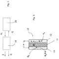
- Figure 1 shows a general diagram illustrating a principle relating to the proposed feeding system.
- a fuel cell 10 and a hydride hydrogen tank 20 are shown. Said tank 20 feeds hydrogen H 2 towards the fuel cell 10. Said fuel cell 10 produces, in known fashion, electrical energy and available excess heat Q which is dissipated to the exterior environment and, according to the invention, to the hydride tank 20.
- the principle underlying the present invention is to recover the heat necessary to the desorption of hydrogen directly by the final user, i.e. plausibly the fuel cell.
- FIG. 2 shows by reference the fuel cell 10 in greater detail.
- Said fuel cell 10 comprises a cathode 11 and an anode 12, separated by an electrolyte 13.
- the oxygen 02 in known fashion, flows into the cathode 11, whilst the hydrogen H 2 flows into the anode 12.
- the electrolyte 13 occurs the ionic migration of hydrogen ions H + with generation of electrons e- at the anode 12 and water H 2 O at the cathode 11.
- FIG. 3a and 3b shows a first embodiment of the storage tank according to the invention, in which a fuel cell 110 comprises an anode 112 made of hydride material absorbing 122 the hydrogen gas.
- Figure 3b which represents the absorbing hydride material 122 comprising grains of metal hydride 122' and gaseous hydrogen in the interstices 122' '
- a metal that generates hydride MH tends to transfer electrons to the hydrogen and hence it can be oxidised at least as much as hydrogen. Consequently, contact with the anodic environment must be avoided.
- Figure 4 shows an embodiment in which the anode 112 and the tank 120 are contiguous, but separated by a wall 123.
- the hydrogen H 2 is provided to the anode 12 through an appropriate conduit 124.
- FIG. 5 shows a second embodiment, which prevents only electrical contact between the anode 12 and the tank 120 by means of a porous baffle 125.
- PEMFC Proton Exchange Membrane Fuel Cells
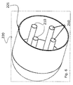
- Figure 6 shows the outline diagram of a preferred version of the feeding system for fuel cells according to the invention, in which is substantially provided a tank 220 which contains the fuel cells within it.
- Said tank 220 is conceived in such a way as to separate the environments relating to the hydrogen absorbing material and to the anode, in such a way that they only exchange heat, confining humidity in the cell by means of a pressure difference between the tank and the cell, and with a geometry that facilitates the heat exchange.
- said tank 220 comprises a cylindrical case 221, preferably made of R800 steel, in which are placed cylindrically shaped fuel cells 210.
- the space between the cylindrical case 221 and the fuel cells 210 is filled with hydride material 122, which therefore is in thermal contact with the fuel cells 210.
- Figure 7 shows the tank 220 with cylindrical fuel tanks 210 with dimensions approaching the real ones. As shown in Figure 7a, several tens of cylindrical fuel cells 210 are arranged with their main axes parallel to the main axis of the cylindrical case 221, constituting a cell bundle.
- Figure 7b shows a cell 210 in detail. It comprises, in a structure of coaxially positioned elements, a protective case 215, which contains a cylindrical cathode 211. Between the protective case 215 and the cylindrical cathode 211 are provided channels 216 for the oxygen. Inside the cylindrical cathode 211 is positioned a cylindrical electrolyte 213, which in turn contains a cylindrical anode 212. Said cylindrical anode 212 contains in its inside a conduit 217 for the passage of a diathermic fluid. On the outer surface of the conduit 217, in contact with the cylindrical anode 212 are provided with the channels 218 for hydrogen.
- the cylindrical cell 210 shown in Figure 7b is of the PEMFC type with absorbing material 122 in the tank of TiFe hydride.
- the proposed system the characteristics of the individual elements are mutually constrained.
- the choice of the absorbing material, for example, is constrained by the working temperature.
- the pressure provided by a hydride tank is a function of temperature, and therefore it is necessary to work at a temperature that guarantees, at least, the delivery of hydrogen at 1 bar.
- magnesium which can absorb 7.6% by weight of hydrogen in MgH 2 .
- This material provides the equilibrium pressure of 1 bar at over 200°C; therefore, a heat source at over 200°C is necessary for desorption.
- AFC alkaline
- PAFC Phosphoric Acid
- the electrical power that is exploited is a function of the active electrochemical surface area, which for 20kW is about 6.6 m 2 for PEMFC cells in maximum efficiency conditions.
- the volume of the tank was calculated as "petrol energy equivalent”: in a model, a volume of magnesium equivalent to 50 1 of petrol was considered, in the other one 25 1 and in the "micro” model, 11.5 ml. Based on these data, the required number of cells is calculated, assuming that a cylindrical geometry in a diameter of 2 or 3 cm is obtainable, taking into account also the volumetric expansion from metal to hydride (19.3% in the AFC cell) and the weight of an external case with a maximum resistance of 30 bar.
- PEMFC cell for automotive use AFC cell for automotive use
- PEMFC microcell Absorbent material TiFe Mg TiFe Working temperature 60 °C 200-250 °C 60°C Dimensions (length x diameter) 70x44 cm 70x55 cm 3x4 cm Tank volume 65 l 110 28 ml Equivalent petrol volume 25 l 50 l 11.5 ml Electrical power 20 kW 20kW 5W Active cell surface area 6,6 m 2 5,9 m 2 20 cm 2 Cell diameter 2-3 cm 2-3 cm 2 cm Number of cells 160-100 150-90 1 Weight of case (30 bar) 4.9 Kg 7.9 Kg 0.6 g Total weight 390-440 Kg 280-330 Kg 170 g Electrical power density 0.19 kW/dm 3 0.11 kW/dm 3 0.13 KW/dm 3
- the above table enables to evaluate the final characteristics of a system like the proposed one by simple energy and mass balances.
- the thermal control of the system provides for the possibility of maintaining the working temperature solely with residual heat, which amounts to 10-20% of the enthalpy of combustion of hydrogen.
- the proposed system advantageously allows to recover the heat necessary to the desorption of hydrogen directly by the final user, i.e. the fuel cell. Feasibility is dictated by the numbers: the fuel cell has an electrical efficiency of about 50%, and hence it also produces 50% of heat.
- the enthalpy of desorption of hydrogen varies from hydride to hydride, but for materials of practical interest it can be evaluated between 30% and 40% of the enthalpy of combustion of hydrogen, hence such values fall within the available excess heat.
Landscapes
- Life Sciences & Earth Sciences (AREA)
- Engineering & Computer Science (AREA)
- Manufacturing & Machinery (AREA)
- Sustainable Development (AREA)
- Sustainable Energy (AREA)
- Chemical & Material Sciences (AREA)
- Chemical Kinetics & Catalysis (AREA)
- Electrochemistry (AREA)
- General Chemical & Material Sciences (AREA)
- Fuel Cell (AREA)
- Filling Or Discharging Of Gas Storage Vessels (AREA)
Abstract
Description
- The present invention relates to a system for feeding gaseous fuel, in particular hydrogen, for fuel cells which comprises a storage tank for said gaseous fuel of the type comprising a case containing a material absorbing said gaseous fuel, in particular a metal hydride, and means for applying an amount of heat to said material absorbing gaseous fuel and determining the flow of said gaseous fuel from said absorbing material towards an anode of a fuel cell.
- In the field of hydrogen operated fuel cells, there is the need to store hydrogen in a form that is particularly convenient for use.
- With regard to storage in bottles, the volumetric energy content of compressed hydrogen is very low, if compared for example to that of petrol. Even operating at high pressure and accepting the potential risk entailed by operation at high pressures, the disadvantage in terms of volumetric energy content remains marked. The liquefaction of hydrogen allows to obtain the most convenient form to handle for storage, with an appreciable energy content. However, electrical energy expenditure for liquefaction accounts for about 50% of the enthalpy of combustion of hydrogen, so the energy balance appears unfavourable.
- To obtain a better volumetric energy content, therefore, the prior art provides for storing the hydrogen to be used to feed the combustion in volumes of metal hydrides, such as magnesium hydride MgH2 or nickel magnesium hydride Mg2NiH4.
- The energy required to confine hydrogen in this state is less than the energy required by the liquefaction process, but the energy required to free hydrogen from the hydride compound is thermal and not electrical. This makes the use of hydride storage tanks in connection with fuel cells difficult because of the need to provide thermal energy to the tank and hence to operate at high temperatures.
- The object of the present invention is to provide a solution capable freeing hydrogen in efficient and convenient fashion in a hydride tank for fuel cells.
- According to the present invention, said object is achieved thanks to a storage tank for fuel cells having the characteristics specifically set out in the annexedclaims.
- As will be readily apparent, in the preferred form of the invention the system for feeding gaseous fuel, in particular hydrogen, for fuel cells comprises a storage tank for said gaseous fuel having a case containing a material absorbing said gaseous fuel, in particular a metal hydride, and means for applying an amount of heat to said material absorbing gaseous fuel and determining the flow of said gaseous fuel from said absorbing material towards an anode of one or more fuel cells, characterised in that said storage tank and said one or more fuel cells are mutually arranged in such a way as to achieve a heat exchange relationship between said anode of one or more fuel cells and said gas absorbing material, said means for applying an amount of heat comprising said heat exchange between said anode of one or more fuel cells and said gas absorbing material.
- This is obtained in particular inserting a plurality of fuel cells inside the case of the storage tank, in heat exchange with the metal hydride that is in its turn contained in the case.
- The invention shall now be described with reference to the accompanying drawings, provided purely by way of non limiting example, in which:
- Figure 1 is a block diagram representing a feeding system for fuel cell according to the invention;
- Figure 2 is a schematic representation of a first embodiment of the system according to the invention;
- Figures 3a and 3b are respectively is a schematic representation and a detail of a second embodiment of the system according to the invention;
- Figure 4 is a schematic representation of a third embodiment of the system according to the invention;
- Figure 5 is a schematic representation of a third embodiment of the system according to the invention;
- - Figure 6 is a schematic view of a preferred embodiment of the system according to the invention;
- Figures 7a and 7b show details of the embodiment of Figure 6.
- Figure 1 shows a general diagram illustrating a principle relating to the proposed feeding system.
- A
fuel cell 10 and ahydride hydrogen tank 20 are shown. Saidtank 20 feeds hydrogen H2 towards thefuel cell 10. Saidfuel cell 10 produces, in known fashion, electrical energy and available excess heat Q which is dissipated to the exterior environment and, according to the invention, to thehydride tank 20. - Thus, the principle underlying the present invention is to recover the heat necessary to the desorption of hydrogen directly by the final user, i.e. plausibly the fuel cell.
- Figure 2 shows by reference the
fuel cell 10 in greater detail. Saidfuel cell 10 comprises acathode 11 and ananode 12, separated by anelectrolyte 13. Theoxygen 02, in known fashion, flows into thecathode 11, whilst the hydrogen H2 flows into theanode 12. In theelectrolyte 13 occurs the ionic migration of hydrogen ions H+ with generation of electrons e- at theanode 12 and water H2O at thecathode 11. - Figures 3a and 3b shows a first embodiment of the storage tank according to the invention, in which a
fuel cell 110 comprises ananode 112 made of hydride material absorbing 122 the hydrogen gas. - However, as shown in Figure 3b which represents the absorbing
hydride material 122 comprising grains of metal hydride 122' and gaseous hydrogen in the interstices 122' ' , by definition, a metal that generates hydride MH tends to transfer electrons to the hydrogen and hence it can be oxidised at least as much as hydrogen. Consequently, contact with the anodic environment must be avoided. - Figure 4 shows an embodiment in which the
anode 112 and thetank 120 are contiguous, but separated by awall 123. The hydrogen H2 is provided to theanode 12 through anappropriate conduit 124. - Figure 5 shows a second embodiment, which prevents only electrical contact between the
anode 12 and thetank 120 by means of aporous baffle 125. Unfortunately electrolytes at low and medium temperature are always based on a liquid constituent, which in Proton Exchange Membrane Fuel Cells (PEMFC) is constituted by water. Environments interfaced with a liquid rapidly reach saturation equilibrium, and humidity is a factor that would deteriorate the absorbing material. - Figure 6 shows the outline diagram of a preferred version of the feeding system for fuel cells according to the invention, in which is substantially provided a
tank 220 which contains the fuel cells within it. - Said
tank 220 is conceived in such a way as to separate the environments relating to the hydrogen absorbing material and to the anode, in such a way that they only exchange heat, confining humidity in the cell by means of a pressure difference between the tank and the cell, and with a geometry that facilitates the heat exchange. - Since the spaces are pressurised, a cylindrical/spherical geometry is adequate. To simplify the system, a cylindrical model is proposed.
- As shown in Figure 6, thus, said
tank 220 comprises acylindrical case 221, preferably made of R800 steel, in which are placed cylindrically shapedfuel cells 210. The space between thecylindrical case 221 and thefuel cells 210 is filled withhydride material 122, which therefore is in thermal contact with thefuel cells 210. - Figure 7 shows the
tank 220 withcylindrical fuel tanks 210 with dimensions approaching the real ones. As shown in Figure 7a, several tens ofcylindrical fuel cells 210 are arranged with their main axes parallel to the main axis of thecylindrical case 221, constituting a cell bundle. - Figure 7b shows a
cell 210 in detail. It comprises, in a structure of coaxially positioned elements, aprotective case 215, which contains acylindrical cathode 211. Between theprotective case 215 and thecylindrical cathode 211 are providedchannels 216 for the oxygen. Inside thecylindrical cathode 211 is positioned acylindrical electrolyte 213, which in turn contains a cylindrical anode 212. Said cylindrical anode 212 contains in its inside aconduit 217 for the passage of a diathermic fluid. On the outer surface of theconduit 217, in contact with the cylindrical anode 212 are provided with thechannels 218 for hydrogen. - The
cylindrical cell 210 shown in Figure 7b is of the PEMFC type with absorbingmaterial 122 in the tank of TiFe hydride. - In general, the proposed system the characteristics of the individual elements are mutually constrained. The choice of the absorbing material, for example, is constrained by the working temperature. The pressure provided by a hydride tank is a function of temperature, and therefore it is necessary to work at a temperature that guarantees, at least, the delivery of hydrogen at 1 bar. There are materials that deliver this pressure at ambient temperature, among which the best known is the aforementioned TiFe, which has a gravimetric content of about 2%.
- To improve this aspect, therefore, it is possible to use as absorbing material magnesium, which can absorb 7.6% by weight of hydrogen in MgH2. This material provides the equilibrium pressure of 1 bar at over 200°C; therefore, a heat source at over 200°C is necessary for desorption. Hence, we are outside the range of proton exchange membrane fuel cells. Cells that operate at this temperature must necessarily use a high boiling electrolyte, and "alkaline" (AFC) and "Phosphoric Acid" (PAFC) fuel cells have been obtained.
- As a result of these considerations, models were developed based on two pairings:
- PEMFC cells - TiFe hydride
- AFC (or PAFC) cells - Mg hydride
- Values relating to cells for two different types of applications are provided here:
- automotive use -
electrical power 20 kW; - micro-apparatus for electrical generation - electrical power 5 W
- The electrical power that is exploited is a function of the active electrochemical surface area, which for 20kW is about 6.6 m2 for PEMFC cells in maximum efficiency conditions.
- The volume of the tank was calculated as "petrol energy equivalent": in a model, a volume of magnesium equivalent to 50 1 of petrol was considered, in the other one 25 1 and in the "micro" model, 11.5 ml. Based on these data, the required number of cells is calculated, assuming that a cylindrical geometry in a diameter of 2 or 3 cm is obtainable, taking into account also the volumetric expansion from metal to hydride (19.3% in the AFC cell) and the weight of an external case with a maximum resistance of 30 bar.
- The data obtained are shown in the following table:
PEMFC cell for automotive use AFC cell for automotive use PEMFC microcell Absorbent material TiFe Mg TiFe Working temperature 60 °C 200-250 °C 60°C Dimensions (length x diameter) 70x44 cm 70x55 cm 3x4 cm Tank volume 65 l 110 28 ml Equivalent petrol volume 25 l 50 l 11.5 ml Electrical power 20 kW 20kW 5W Active cell surface area 6,6 m2 5,9 m 220 cm2 Cell diameter 2-3 cm 2-3 cm 2 cm Number of cells 160-100 150-90 1 Weight of case (30 bar) 4.9 Kg 7.9 Kg 0.6 g Total weight 390-440 Kg 280-330 Kg 170 g Electrical power density 0.19 kW/dm3 0.11 kW/dm3 0.13 KW/dm3 - The above table enables to evaluate the final characteristics of a system like the proposed one by simple energy and mass balances.
- The thermal control of the system provides for the possibility of maintaining the working temperature solely with residual heat, which amounts to 10-20% of the enthalpy of combustion of hydrogen.
- The solution described above allows to achieve considerable advantages with respect to known solutions.
- The proposed system advantageously allows to recover the heat necessary to the desorption of hydrogen directly by the final user, i.e. the fuel cell. Feasibility is dictated by the numbers: the fuel cell has an electrical efficiency of about 50%, and hence it also produces 50% of heat. The enthalpy of desorption of hydrogen varies from hydride to hydride, but for materials of practical interest it can be evaluated between 30% and 40% of the enthalpy of combustion of hydrogen, hence such values fall within the available excess heat.
- Therefore, with the described system hydrogen can be stored at a series of advantageous conditions:
- high volumetric density
- low working pressures: savings in materials and technology, and safety of operation
- nearly nil energy cost, since excess energy is exploited.
- Naturally, without altering the principle of the invention, the construction details and the embodiment may vary widely from what is described and illustrated purely by way of example herein, without thereby departing from the scope of the present invention.
- For example, it is clear that even if the means for applying an amount of heat to the metal hydride that constitutes the material absorbing gaseous fuel are mainly obtained through the heat exchange between the anode and the metal hydride determined by the mutual arrangement of the tank and of the fuel cells, additional means for applying heat may also be provided in association with the tank.
Claims (15)
- System for feeding gaseous fuel, in particular hydrogen, for fuel cells which comprises a storage tank (20; 120; 220) for said gaseous fuel (H2) of the type comprising a case (221) containing a material (122) absorbing said gaseous fuel (H2), in particular a metal hydride, and means for applying an amount of heat (Q) to said material (122) absorbing gaseous fuel and for determining the flow of said gaseous fuel (H2) from said absorbing material (122) towards an anode (12; 112; 212) of one or more fuel cells (10; 110; 210), characterised in that said storage tank (110; 210) and said one or more fuel cells (110; 210) are mutually arranged in such a way as to achieve a heat exchange relationship between said anode (112; 212) of one or more fuel cells (110; 210) and said gas absorbing material (122), said means for applying an amount of heat (Q) comprising said heat exchange between said anode (112; 212) of one or more fuel cells (110; 210) and said gas absorbing material (122).
- System as claimed in claim 1, characterised in that said anode (112; 212) comprises at least one wall (124, 125) in contact with said storage tank (120; 220) to achieve said heat exchange.
- System as claimed in claim 2, characterised in that said wall (125) comprises a porous baffle.
- System as claimed in one or more of claims 1 to 3, characterised in that said case (221) of said storage tank (220) contains at least in part said anode (212).
- System as claimed in claim 4, characterised in that said case (221) of said storage tank (221) contains one or more fuel cells (210).
- System as claimed in claim 5, characterised in that said one or more fuel cells (210) comprise a cathode (211), containing a channel (217) for the passage of a diathermic fluid, said cathode (211) being contained within an electrolyte element (213), said electrolyte element (213) being contained within said anode (212).
- System as claimed in claim 6, characterised in that said case (221), said anode (212), said electrolyte element (213) and said cathode (211) have substantially hollow cylinder or tubular shape and are arranged coaxial to each other.
- System as claimed in one or more of claims 1 to 7, characterised in that a pressure difference is applied between the storage tank (120; 220) and one or more fuel cells (110; 210).
- System as claimed in claim 2, characterised in that said it comprises a conduit (124) for the flow of the gaseous fuel from the storage tank (120) to the anode (112) of the fuel cell (110).
- System as claimed in one of the claims 1 through 9, characterised in that said gaseous fuel (H2) is hydrogen.
- System as claimed in one of the claims 1 through 10, characterised in that said gas absorbing material is a metallic hydride, in particular Titanium Iron hydride or magnesium hydride.
- System as claimed in one of the claims 1 through 11, characterised in that said fuel cell is a Proton Exchange Membrane Fuel Cell or micro-cell (PEMFC) and said gas absorbing material is titanium-iron hydride.
- System as claimed in one of the claims 1 through 11, characterised in that said fuel cell is an "alkaline" (AFC) or "phosphoric acid" (PAFC) fuel cell and said gas absorbing material is magnesium hydride.
- Storage tank for gaseous fuel suitable for operating in the system as claimed in one or more of the claims 1 to 13.
- Gaseous fuel cell suitable for operating in the system as claimed in one or more of the claims 1 to 13.
Priority Applications (4)
| Application Number | Priority Date | Filing Date | Title |
|---|---|---|---|
| AT05425127T ATE413694T1 (en) | 2005-03-07 | 2005-03-07 | HYDROGEN SUPPLY SYSTEM FOR FUEL CELL |
| EP05425127A EP1701403B1 (en) | 2005-03-07 | 2005-03-07 | A system for feeding gaseous fuel, in particular hydrogen, for fuel cells |
| DE602005010818T DE602005010818D1 (en) | 2005-03-07 | 2005-03-07 | Hydrogen supply system for fuel cell |
| US11/365,809 US7504171B2 (en) | 2005-03-07 | 2006-03-02 | System for feeding gaseous fuel, in particular hydrogen, for fuel cells |
Applications Claiming Priority (1)
| Application Number | Priority Date | Filing Date | Title |
|---|---|---|---|
| EP05425127A EP1701403B1 (en) | 2005-03-07 | 2005-03-07 | A system for feeding gaseous fuel, in particular hydrogen, for fuel cells |
Publications (2)
| Publication Number | Publication Date |
|---|---|
| EP1701403A1 true EP1701403A1 (en) | 2006-09-13 |
| EP1701403B1 EP1701403B1 (en) | 2008-11-05 |
Family
ID=34943085
Family Applications (1)
| Application Number | Title | Priority Date | Filing Date |
|---|---|---|---|
| EP05425127A Expired - Lifetime EP1701403B1 (en) | 2005-03-07 | 2005-03-07 | A system for feeding gaseous fuel, in particular hydrogen, for fuel cells |
Country Status (4)
| Country | Link |
|---|---|
| US (1) | US7504171B2 (en) |
| EP (1) | EP1701403B1 (en) |
| AT (1) | ATE413694T1 (en) |
| DE (1) | DE602005010818D1 (en) |
Families Citing this family (1)
| Publication number | Priority date | Publication date | Assignee | Title |
|---|---|---|---|---|
| US7989115B2 (en) * | 2007-12-14 | 2011-08-02 | Gore Enterprise Holdings, Inc. | Highly stable fuel cell membranes and methods of making them |
Citations (7)
| Publication number | Priority date | Publication date | Assignee | Title |
|---|---|---|---|---|
| US4826741A (en) * | 1987-06-02 | 1989-05-02 | Ergenics Power Systems, Inc. | Ion exchange fuel cell assembly with improved water and thermal management |
| EP0917225A1 (en) * | 1997-11-07 | 1999-05-19 | Matsushita Electric Industrial Co., Ltd. | Portable fuel cell apparatus containing hydrogen storage tank |
| US5932365A (en) * | 1997-06-09 | 1999-08-03 | Industrial Technology Research Institute | Hydrogen canister fuel cell battery |
| US20020045079A1 (en) * | 2000-10-12 | 2002-04-18 | Honda Giken Kogyo Kabushiki Kaisha | Hydrogen supply device |
| US6406808B1 (en) * | 2000-04-10 | 2002-06-18 | Motorola, Inc. | Method and apparatus for thermal management of fuel cell systems |
| US20030022031A1 (en) * | 2001-07-25 | 2003-01-30 | Ballard Power Systems Inc. | Fuel cell system automatic power switching method and apparatus |
| EP1327606A1 (en) * | 2000-10-02 | 2003-07-16 | Tohoku Techno Arch Co., Ltd. | Method of absorption-desorption of hydrogen storage alloy and hydrogen storage alloy and fuel cell using said method |
Family Cites Families (5)
| Publication number | Priority date | Publication date | Assignee | Title |
|---|---|---|---|---|
| JP4131038B2 (en) * | 1998-06-26 | 2008-08-13 | 株式会社エクォス・リサーチ | Fuel cell system |
| JP3741009B2 (en) * | 2001-09-07 | 2006-02-01 | トヨタ自動車株式会社 | Fuel cell system |
| US20030232229A1 (en) * | 2002-06-17 | 2003-12-18 | Bergqvist Rene Stig | Cooling arrangement |
| US6918430B2 (en) * | 2002-08-14 | 2005-07-19 | Texaco Ovonic Hydrogen Systems Llc | Onboard hydrogen storage unit with heat transfer system for use in a hydrogen powered vehicle |
| JP4675029B2 (en) * | 2003-03-17 | 2011-04-20 | トヨタ自動車株式会社 | Fuel cell system and hydrogen storage method |
-
2005
- 2005-03-07 DE DE602005010818T patent/DE602005010818D1/en active Active
- 2005-03-07 AT AT05425127T patent/ATE413694T1/en not_active IP Right Cessation
- 2005-03-07 EP EP05425127A patent/EP1701403B1/en not_active Expired - Lifetime
-
2006
- 2006-03-02 US US11/365,809 patent/US7504171B2/en not_active Expired - Fee Related
Patent Citations (7)
| Publication number | Priority date | Publication date | Assignee | Title |
|---|---|---|---|---|
| US4826741A (en) * | 1987-06-02 | 1989-05-02 | Ergenics Power Systems, Inc. | Ion exchange fuel cell assembly with improved water and thermal management |
| US5932365A (en) * | 1997-06-09 | 1999-08-03 | Industrial Technology Research Institute | Hydrogen canister fuel cell battery |
| EP0917225A1 (en) * | 1997-11-07 | 1999-05-19 | Matsushita Electric Industrial Co., Ltd. | Portable fuel cell apparatus containing hydrogen storage tank |
| US6406808B1 (en) * | 2000-04-10 | 2002-06-18 | Motorola, Inc. | Method and apparatus for thermal management of fuel cell systems |
| EP1327606A1 (en) * | 2000-10-02 | 2003-07-16 | Tohoku Techno Arch Co., Ltd. | Method of absorption-desorption of hydrogen storage alloy and hydrogen storage alloy and fuel cell using said method |
| US20020045079A1 (en) * | 2000-10-12 | 2002-04-18 | Honda Giken Kogyo Kabushiki Kaisha | Hydrogen supply device |
| US20030022031A1 (en) * | 2001-07-25 | 2003-01-30 | Ballard Power Systems Inc. | Fuel cell system automatic power switching method and apparatus |
Also Published As
| Publication number | Publication date |
|---|---|
| DE602005010818D1 (en) | 2008-12-18 |
| US20060199066A1 (en) | 2006-09-07 |
| US7504171B2 (en) | 2009-03-17 |
| ATE413694T1 (en) | 2008-11-15 |
| EP1701403B1 (en) | 2008-11-05 |
Similar Documents
| Publication | Publication Date | Title |
|---|---|---|
| US6742650B2 (en) | Metal hydride storage canister design and its manufacture | |
| US7781109B2 (en) | Hydrogen storage and integrated fuel cell assembly | |
| US6080501A (en) | Fuel cell with integral fuel storage | |
| US8227144B2 (en) | Cellular reservoir and methods related thereto | |
| US11408082B2 (en) | Electrochemical compression system | |
| JP5711687B2 (en) | Electrochemical device and power storage system | |
| JP2746751B2 (en) | Method and apparatus for charging and discharging electrical energy | |
| JP6285867B2 (en) | Tanks that store hydrogen in the form of metal hydrides | |
| EP3208877B1 (en) | Solid state hydrogen storage device | |
| US6991719B2 (en) | Method for producing and transporting hydrogen | |
| EP1404578B1 (en) | Atomically engineered hydrogen storage alloys having extended storage capacity at high pressures and high pressure hydrogen storage units containing variable amounts thereof | |
| US20090226776A1 (en) | Hydrogen charging apparatus | |
| JP2004342584A (en) | Battery with small SOFC fuel cell | |
| US20100261094A1 (en) | Apparatus for containing metal-organic frameworks | |
| EP1286406B1 (en) | Metal hydride storage canister and its manufacture | |
| EP1701403B1 (en) | A system for feeding gaseous fuel, in particular hydrogen, for fuel cells | |
| KR20180132139A (en) | Rechargeable electrochemical device for producing electrical energy | |
| JP4261918B2 (en) | Fuel cartridge for fuel cell and fuel cell | |
| JP2009541968A (en) | Fuel supply system for fuel cell | |
| US20070172715A1 (en) | Compact, modular regenerative fuel cell | |
| JP2002022097A (en) | Storage container for hydrogen storage alloy | |
| T-Raissi et al. | Metal hydride storage requirements for transportation applications | |
| Reissner et al. | Development of a hydrogen and heat storage system for satellite applications | |
| CN120283329A (en) | Battery energy storage container and method of use thereof | |
| Reissner | Metal Hydrides as Enabling Technology for the use of Hydrogen-Based Energy Storage Systems on Telecommunication Satellites |
Legal Events
| Date | Code | Title | Description |
|---|---|---|---|
| PUAI | Public reference made under article 153(3) epc to a published international application that has entered the european phase |
Free format text: ORIGINAL CODE: 0009012 |
|
| AK | Designated contracting states |
Kind code of ref document: A1 Designated state(s): AT BE BG CH CY CZ DE DK EE ES FI FR GB GR HU IE IS IT LI LT LU MC NL PL PT RO SE SI SK TR |
|
| AX | Request for extension of the european patent |
Extension state: AL BA HR LV MK YU |
|
| 17P | Request for examination filed |
Effective date: 20070130 |
|
| AKX | Designation fees paid |
Designated state(s): AT BE BG CH CY CZ DE DK EE ES FI FR GB GR HU IE IS IT LI LT LU MC NL PL PT RO SE SI SK TR |
|
| 17Q | First examination report despatched |
Effective date: 20070604 |
|
| GRAP | Despatch of communication of intention to grant a patent |
Free format text: ORIGINAL CODE: EPIDOSNIGR1 |
|
| GRAS | Grant fee paid |
Free format text: ORIGINAL CODE: EPIDOSNIGR3 |
|
| GRAA | (expected) grant |
Free format text: ORIGINAL CODE: 0009210 |
|
| AK | Designated contracting states |
Kind code of ref document: B1 Designated state(s): AT BE BG CH CY CZ DE DK EE ES FI FR GB GR HU IE IS IT LI LT LU MC NL PL PT RO SE SI SK TR |
|
| REG | Reference to a national code |
Ref country code: GB Ref legal event code: FG4D |
|
| REG | Reference to a national code |
Ref country code: CH Ref legal event code: EP |
|
| REG | Reference to a national code |
Ref country code: IE Ref legal event code: FG4D |
|
| REF | Corresponds to: |
Ref document number: 602005010818 Country of ref document: DE Date of ref document: 20081218 Kind code of ref document: P |
|
| NLV1 | Nl: lapsed or annulled due to failure to fulfill the requirements of art. 29p and 29m of the patents act | ||
| LTIE | Lt: invalidation of european patent or patent extension |
Effective date: 20081105 |
|
| PG25 | Lapsed in a contracting state [announced via postgrant information from national office to epo] |
Ref country code: ES Free format text: LAPSE BECAUSE OF FAILURE TO SUBMIT A TRANSLATION OF THE DESCRIPTION OR TO PAY THE FEE WITHIN THE PRESCRIBED TIME-LIMIT Effective date: 20090216 Ref country code: LT Free format text: LAPSE BECAUSE OF FAILURE TO SUBMIT A TRANSLATION OF THE DESCRIPTION OR TO PAY THE FEE WITHIN THE PRESCRIBED TIME-LIMIT Effective date: 20081105 Ref country code: AT Free format text: LAPSE BECAUSE OF FAILURE TO SUBMIT A TRANSLATION OF THE DESCRIPTION OR TO PAY THE FEE WITHIN THE PRESCRIBED TIME-LIMIT Effective date: 20081105 |
|
| PG25 | Lapsed in a contracting state [announced via postgrant information from national office to epo] |
Ref country code: IS Free format text: LAPSE BECAUSE OF FAILURE TO SUBMIT A TRANSLATION OF THE DESCRIPTION OR TO PAY THE FEE WITHIN THE PRESCRIBED TIME-LIMIT Effective date: 20090305 Ref country code: PL Free format text: LAPSE BECAUSE OF FAILURE TO SUBMIT A TRANSLATION OF THE DESCRIPTION OR TO PAY THE FEE WITHIN THE PRESCRIBED TIME-LIMIT Effective date: 20081105 Ref country code: SI Free format text: LAPSE BECAUSE OF FAILURE TO SUBMIT A TRANSLATION OF THE DESCRIPTION OR TO PAY THE FEE WITHIN THE PRESCRIBED TIME-LIMIT Effective date: 20081105 Ref country code: FI Free format text: LAPSE BECAUSE OF FAILURE TO SUBMIT A TRANSLATION OF THE DESCRIPTION OR TO PAY THE FEE WITHIN THE PRESCRIBED TIME-LIMIT Effective date: 20081105 Ref country code: NL Free format text: LAPSE BECAUSE OF FAILURE TO SUBMIT A TRANSLATION OF THE DESCRIPTION OR TO PAY THE FEE WITHIN THE PRESCRIBED TIME-LIMIT Effective date: 20081105 |
|
| PG25 | Lapsed in a contracting state [announced via postgrant information from national office to epo] |
Ref country code: EE Free format text: LAPSE BECAUSE OF FAILURE TO SUBMIT A TRANSLATION OF THE DESCRIPTION OR TO PAY THE FEE WITHIN THE PRESCRIBED TIME-LIMIT Effective date: 20081105 Ref country code: DK Free format text: LAPSE BECAUSE OF FAILURE TO SUBMIT A TRANSLATION OF THE DESCRIPTION OR TO PAY THE FEE WITHIN THE PRESCRIBED TIME-LIMIT Effective date: 20081105 Ref country code: BE Free format text: LAPSE BECAUSE OF FAILURE TO SUBMIT A TRANSLATION OF THE DESCRIPTION OR TO PAY THE FEE WITHIN THE PRESCRIBED TIME-LIMIT Effective date: 20081105 Ref country code: RO Free format text: LAPSE BECAUSE OF FAILURE TO SUBMIT A TRANSLATION OF THE DESCRIPTION OR TO PAY THE FEE WITHIN THE PRESCRIBED TIME-LIMIT Effective date: 20081105 Ref country code: BG Free format text: LAPSE BECAUSE OF FAILURE TO SUBMIT A TRANSLATION OF THE DESCRIPTION OR TO PAY THE FEE WITHIN THE PRESCRIBED TIME-LIMIT Effective date: 20090205 |
|
| PG25 | Lapsed in a contracting state [announced via postgrant information from national office to epo] |
Ref country code: PT Free format text: LAPSE BECAUSE OF FAILURE TO SUBMIT A TRANSLATION OF THE DESCRIPTION OR TO PAY THE FEE WITHIN THE PRESCRIBED TIME-LIMIT Effective date: 20090406 Ref country code: CZ Free format text: LAPSE BECAUSE OF FAILURE TO SUBMIT A TRANSLATION OF THE DESCRIPTION OR TO PAY THE FEE WITHIN THE PRESCRIBED TIME-LIMIT Effective date: 20081105 Ref country code: SE Free format text: LAPSE BECAUSE OF FAILURE TO SUBMIT A TRANSLATION OF THE DESCRIPTION OR TO PAY THE FEE WITHIN THE PRESCRIBED TIME-LIMIT Effective date: 20090205 |
|
| PLBE | No opposition filed within time limit |
Free format text: ORIGINAL CODE: 0009261 |
|
| STAA | Information on the status of an ep patent application or granted ep patent |
Free format text: STATUS: NO OPPOSITION FILED WITHIN TIME LIMIT |
|
| PG25 | Lapsed in a contracting state [announced via postgrant information from national office to epo] |
Ref country code: SK Free format text: LAPSE BECAUSE OF FAILURE TO SUBMIT A TRANSLATION OF THE DESCRIPTION OR TO PAY THE FEE WITHIN THE PRESCRIBED TIME-LIMIT Effective date: 20081105 |
|
| 26N | No opposition filed |
Effective date: 20090806 |
|
| PG25 | Lapsed in a contracting state [announced via postgrant information from national office to epo] |
Ref country code: MC Free format text: LAPSE BECAUSE OF NON-PAYMENT OF DUE FEES Effective date: 20090331 |
|
| REG | Reference to a national code |
Ref country code: CH Ref legal event code: PL |
|
| GBPC | Gb: european patent ceased through non-payment of renewal fee |
Effective date: 20090307 |
|
| PG25 | Lapsed in a contracting state [announced via postgrant information from national office to epo] |
Ref country code: IE Free format text: LAPSE BECAUSE OF NON-PAYMENT OF DUE FEES Effective date: 20090307 Ref country code: LI Free format text: LAPSE BECAUSE OF NON-PAYMENT OF DUE FEES Effective date: 20090331 Ref country code: CH Free format text: LAPSE BECAUSE OF NON-PAYMENT OF DUE FEES Effective date: 20090331 |
|
| PG25 | Lapsed in a contracting state [announced via postgrant information from national office to epo] |
Ref country code: GB Free format text: LAPSE BECAUSE OF NON-PAYMENT OF DUE FEES Effective date: 20090307 |
|
| PG25 | Lapsed in a contracting state [announced via postgrant information from national office to epo] |
Ref country code: GR Free format text: LAPSE BECAUSE OF FAILURE TO SUBMIT A TRANSLATION OF THE DESCRIPTION OR TO PAY THE FEE WITHIN THE PRESCRIBED TIME-LIMIT Effective date: 20090206 |
|
| PG25 | Lapsed in a contracting state [announced via postgrant information from national office to epo] |
Ref country code: LU Free format text: LAPSE BECAUSE OF NON-PAYMENT OF DUE FEES Effective date: 20090307 |
|
| PG25 | Lapsed in a contracting state [announced via postgrant information from national office to epo] |
Ref country code: HU Free format text: LAPSE BECAUSE OF FAILURE TO SUBMIT A TRANSLATION OF THE DESCRIPTION OR TO PAY THE FEE WITHIN THE PRESCRIBED TIME-LIMIT Effective date: 20090506 |
|
| PG25 | Lapsed in a contracting state [announced via postgrant information from national office to epo] |
Ref country code: TR Free format text: LAPSE BECAUSE OF FAILURE TO SUBMIT A TRANSLATION OF THE DESCRIPTION OR TO PAY THE FEE WITHIN THE PRESCRIBED TIME-LIMIT Effective date: 20081105 |
|
| PG25 | Lapsed in a contracting state [announced via postgrant information from national office to epo] |
Ref country code: CY Free format text: LAPSE BECAUSE OF FAILURE TO SUBMIT A TRANSLATION OF THE DESCRIPTION OR TO PAY THE FEE WITHIN THE PRESCRIBED TIME-LIMIT Effective date: 20081105 |
|
| PGFP | Annual fee paid to national office [announced via postgrant information from national office to epo] |
Ref country code: FR Payment date: 20140311 Year of fee payment: 10 Ref country code: IT Payment date: 20140310 Year of fee payment: 10 |
|
| PGFP | Annual fee paid to national office [announced via postgrant information from national office to epo] |
Ref country code: DE Payment date: 20140417 Year of fee payment: 10 |
|
| REG | Reference to a national code |
Ref country code: DE Ref legal event code: R119 Ref document number: 602005010818 Country of ref document: DE |
|
| PG25 | Lapsed in a contracting state [announced via postgrant information from national office to epo] |
Ref country code: IT Free format text: LAPSE BECAUSE OF NON-PAYMENT OF DUE FEES Effective date: 20150307 |
|
| REG | Reference to a national code |
Ref country code: FR Ref legal event code: ST Effective date: 20151130 |
|
| PG25 | Lapsed in a contracting state [announced via postgrant information from national office to epo] |
Ref country code: DE Free format text: LAPSE BECAUSE OF NON-PAYMENT OF DUE FEES Effective date: 20151001 |
|
| PG25 | Lapsed in a contracting state [announced via postgrant information from national office to epo] |
Ref country code: FR Free format text: LAPSE BECAUSE OF NON-PAYMENT OF DUE FEES Effective date: 20150331 |