EP1701172A1 - RF cable testing - Google Patents
RF cable testing Download PDFInfo
- Publication number
- EP1701172A1 EP1701172A1 EP06110070A EP06110070A EP1701172A1 EP 1701172 A1 EP1701172 A1 EP 1701172A1 EP 06110070 A EP06110070 A EP 06110070A EP 06110070 A EP06110070 A EP 06110070A EP 1701172 A1 EP1701172 A1 EP 1701172A1
- Authority
- EP
- European Patent Office
- Prior art keywords
- cable
- cables
- insertion loss
- test
- measuring
- Prior art date
- Legal status (The legal status is an assumption and is not a legal conclusion. Google has not performed a legal analysis and makes no representation as to the accuracy of the status listed.)
- Withdrawn
Links
- 238000012360 testing method Methods 0.000 title description 75
- 238000003780 insertion Methods 0.000 claims abstract description 56
- 230000037431 insertion Effects 0.000 claims abstract description 56
- 238000000034 method Methods 0.000 claims abstract description 37
- 239000000835 fiber Substances 0.000 claims description 3
- 238000005259 measurement Methods 0.000 description 13
- 239000011159 matrix material Substances 0.000 description 11
- 230000005540 biological transmission Effects 0.000 description 4
- 238000005452 bending Methods 0.000 description 3
- 230000006378 damage Effects 0.000 description 3
- 238000010586 diagram Methods 0.000 description 2
- 238000012423 maintenance Methods 0.000 description 2
- 238000010998 test method Methods 0.000 description 2
- 208000027418 Wounds and injury Diseases 0.000 description 1
- 230000015556 catabolic process Effects 0.000 description 1
- 238000012937 correction Methods 0.000 description 1
- 238000006731 degradation reaction Methods 0.000 description 1
- 238000013461 design Methods 0.000 description 1
- 239000004519 grease Substances 0.000 description 1
- 208000014674 injury Diseases 0.000 description 1
- 238000000691 measurement method Methods 0.000 description 1
- 230000008054 signal transmission Effects 0.000 description 1
- 238000010561 standard procedure Methods 0.000 description 1
- 238000010408 sweeping Methods 0.000 description 1
Images


Classifications
-
- G—PHYSICS
- G01—MEASURING; TESTING
- G01R—MEASURING ELECTRIC VARIABLES; MEASURING MAGNETIC VARIABLES
- G01R27/00—Arrangements for measuring resistance, reactance, impedance, or electric characteristics derived therefrom
- G01R27/28—Measuring attenuation, gain, phase shift or derived characteristics of electric four pole networks, i.e. two-port networks; Measuring transient response
-
- G—PHYSICS
- G01—MEASURING; TESTING
- G01R—MEASURING ELECTRIC VARIABLES; MEASURING MAGNETIC VARIABLES
- G01R31/00—Arrangements for testing electric properties; Arrangements for locating electric faults; Arrangements for electrical testing characterised by what is being tested not provided for elsewhere
- G01R31/08—Locating faults in cables, transmission lines, or networks
- G01R31/11—Locating faults in cables, transmission lines, or networks using pulse reflection methods
Definitions
- This invention relates to methods for testing electrical components, and more particularly to methods for testing electrical cables where the endpoints of the cables or Units Under Test are not physically located close to each other.
- Insertion loss provides a measure of the power loss along a transmission line and is typically measured in dB. Insertion loss varies with the type of cable, operating frequency, and cable length.
- Insertion loss measurements can be used to troubleshoot or to verify cable performance.
- a common instrument for performing these measurements is a vector network analyzer (VNA).
- VNA vector network analyzer
- VNA hardware typically includes a sweeping signal source, a test set to separate forward and reverse signals, and a phase-coherent receiver.
- Scattering Parameters are the reflection and transmission coefficients between the incident and reflection waves. They are used to describe the behavior of a device under linear conditions at radio frequencies. Each parameter is typically characterized by magnitude, decibel and phase. The expression in decibel is 20log(Sij) because s-parameters are voltage ratios of the waves.
- S11 is the reflection coefficient of the input
- S21 is the forward transmission gain
- S12 is the reverse transmission gain
- S22 is the reflection coefficient of the output.
- S12 and S21 measurements (such as Insertion Loss, Time Delay Matching, and Phase Matching) using a VNA usually involve two test cables.
- test cables and adapters After calibrating out the errors due to the VNA, test cables and adapters, one test cable is connected between a first port on the VNA (Port 1) and one end of the cable under test. A second test cable is connected between a second port of the VNA (Port 2) and the other end of the cable under test. Where the endpoints of the cables or Units Under Test are not physically located close to each other, or the test cables have to be routed around obstructions, longer test cables than desired or practical may be necessary to perform S12 or S21 measurements.
- the errors introduced by the test cables can begin to cause inaccuracies in the measurements.
- the cables to be tested are installed in equipment, such as an aircraft, and cannot be easily removed.
- This invention provides a method for measuring insertion loss in cables.
- the electrical components can include, for example, power dividers or splitters.
- the measured characteristics can include, for example, phase and phase match.
- FIGs. 1 through 5 are schematic diagrams of test circuits used to practice the method of the invention.
- FIG. 6 is a schematic representation of a switch matrix that can be used to practice the method of the invention.
- Parallel Cables or Cable Paths means three or more cables with compatible frequency ranges of operation.
- the physical endpoints of the cables should be located near enough to each other so that the same relatively short test cables, item numbers 18 and 20 on FIGs. 1 through 5, can be connected between the VNA Ports and the endpoints of the cables to be tested and the same relatively short wraparound cable, item number 26 on FIGs. 1 through 5, can be connected to the other ends of the cables under test.
- FIG. 1 is a schematic representation of a test circuit 10 used to practice the method of the invention.
- a vector network analyzer (VNA) 12 includes two ports 14 and 16 connected to test cables 18 and 20.
- Test cable 18 is connected to a proximal end of a first cable to be tested, referred to as Cable 1, by a connector 22.
- Test cable 20 is connected to a proximal end of a second cable to be tested, referred to as Cable 2, by a connector 24.
- the distal ends of Cables 1 and 2 are connected to each other by a wraparound cable 26 using connectors 28 and 30.
- the vector network analyzer (VNA) is used to measure the insertion loss of the cable path that includes the series connection of Cables 1 and 2.
- the VNA can be any commercially available VNA. VNAs are commonly used to measure insertion loss.
- the insertion loss in the cable path that includes Cables 1 and 2 is identified as IL 12 .
- the cables to be tested can be mounted in harnesses or connector shells, or routed in such a way where bending them may not be possible. Also, bending cables may not be possible where they cannot physically reach each other. Furthermore, depending on the type of cable and cable characteristics being measured, bending can degrade and sometimes destroy certain cable properties such as Phase Match, and Insertion Loss, or VSWR.
- FIG. 4 is a schematic representation of the test circuit wherein Cables 3 and 4 are connected to the test ports of the vector network analyzer.
- the vector network analyzer is used to measure the insertion loss of the cable path including the series connection of Cables 3 and 4.
- the insertion loss in this cable path is identified as IL 34 .
- FIG. 5 is a schematic representation of the test circuit wherein Cable 3 and another cable referred to as Cable N are connected to the test ports of the vector network analyzer.
- the vector network analyzer is used to measure the insertion loss of the cable path including the series connection of Cables 3 and N.
- the insertion loss in this cable path is identified as IL 3N .
- the method of this invention uses short test cables that are less expensive and have less stringent requirements for insertion loss, ruggedness, and stability than long cables. This results in a lower chance of the test cables causing damage or being damaged during use. In addition, short cables are less intrusive to other tasks being performed in the area.
- FIG. 6 is a schematic diagram of a switch matrix 50 that can be used to connect the ends of a plurality of cables to each other.
- This switch matrix includes a plurality of circuit paths that include switches 52, 54, 56 and 58 that can be used to provide wraparound connections similar to those of FIGs. 1-4.
- the switch characteristics could be calibrated out or switches with known calibrated characteristics could be used. The known characteristics with their tolerance could then be added to the equations that are used to determine the desired characteristics of the cables under test. The way that the switch characteristics are handled would depend on how the matrix is implemented and what assumptions are made. Alternatively, the switch could include a self-calibration wrap. In addition, the switches could be manually operated, computer controlled, or otherwise automated. One way to calibrate the switch matrix would be to connect it directly to the test cables from the VNA and perform a VNA calibration without the cable under test in the path. Then the measured insertion loss can be modified by this measurement.
- the circuit paths of the switch matrix can be matched paths or paths with known characteristics that can be included in the test equations.
- the switches in the wrapping matrix could be internal to a system design or connected to the system externally during testing.
- the switch matrix could be used in conjunction with or as part of a built-in test system to verify performance and/or to develop system correction factors to be used during normal system operation.
- a particular application of the invention can be used for automatic cable testing of four parallel RF paths.
- the method could be extended to include any number of cable paths greater then 3.
- the cables to be measured in this instance were up to 65 feet long and traversed the length of an aircraft. Cables were already installed in the aircraft making removal difficult. Testing of this type is done in a maintenance environment, so ease of measurement and speed of test are important considerations.
- a vector network analyzer under control of a personal computer via a general purpose interface bus (GPIB) link was used to perform all calculations.
- GPS general purpose interface bus
- IL 1 , IL 2 , IL 3 , and IL 4 are the actual insertion losses of cables; and IL 12 , IL 13 , IL 23 , and IL 34 are the measured insertion losses of cable paths 1-2, 1-3, 2-3, and 3-4 respectively.
- I L 1 I L 12 ⁇ I L 23 + I L 13 2
- I L 3 I L 13 ⁇ I L 1
- I L 2 I L 23 ⁇ I L 3
- I L 4 I L 34 ⁇ I L 3
- the method can be applied to any group of three or more cables.
- N the test setups of FIGs. 1-3 can be used to measure IL 12 , IL 13 , and IL 23 .
- a computer controller can be used to allow the calculations to be done with a minimum of effort.
- Similar methods can be used for determining other S12 and S21 type measurements such as phase and phase match between cable paths.
- the invention can also be used to characterize or test systems with devices in the system paths. Such devices can include, for example, power dividers or splitters.
- this method could be used to perform link loss tests of fiber optics cables. Short test cables have a lower failure rate as long test cables. This method could improve maintenance costs in so far as there would be fewer inaccurate results due to faulty test cables.
- the other S12 and S21 parameters could be tested by substituting the desired parameter for insertion loss in the preceding discussion.
Landscapes
- Physics & Mathematics (AREA)
- General Physics & Mathematics (AREA)
- Measurement Of Resistance Or Impedance (AREA)
- Monitoring And Testing Of Transmission In General (AREA)
Abstract
Description
- This invention relates to methods for testing electrical components, and more particularly to methods for testing electrical cables where the endpoints of the cables or Units Under Test are not physically located close to each other.
- In most RF systems, it is common to test cable paths within the system to verify that the cables are capable of signal transmission with minimal degradation. An example of a typical RF cable measurement would be an insertion loss measurement. Insertion loss provides a measure of the power loss along a transmission line and is typically measured in dB. Insertion loss varies with the type of cable, operating frequency, and cable length.
- Insertion loss measurements can be used to troubleshoot or to verify cable performance. A common instrument for performing these measurements is a vector network analyzer (VNA). Vector network analyzers can measure and display the complete amplitude and phase characteristics of an electrical network. VNA hardware typically includes a sweeping signal source, a test set to separate forward and reverse signals, and a phase-coherent receiver.
- Scattering Parameters, or s-parameters, are the reflection and transmission coefficients between the incident and reflection waves. They are used to describe the behavior of a device under linear conditions at radio frequencies. Each parameter is typically characterized by magnitude, decibel and phase. The expression in decibel is 20log(Sij) because s-parameters are voltage ratios of the waves. For a two port network, S11 is the reflection coefficient of the input, S21 is the forward transmission gain, S12 is the reverse transmission gain, and S22 is the reflection coefficient of the output. S12 and S21 measurements (such as Insertion Loss, Time Delay Matching, and Phase Matching) using a VNA usually involve two test cables. After calibrating out the errors due to the VNA, test cables and adapters, one test cable is connected between a first port on the VNA (Port 1) and one end of the cable under test. A second test cable is connected between a second port of the VNA (Port 2) and the other end of the cable under test. Where the endpoints of the cables or Units Under Test are not physically located close to each other, or the test cables have to be routed around obstructions, longer test cables than desired or practical may be necessary to perform S12 or S21 measurements.
- If the length of the test cables significantly exceeds the length of the cables to be tested, the errors introduced by the test cables can begin to cause inaccuracies in the measurements. In many cases, the cables to be tested are installed in equipment, such as an aircraft, and cannot be easily removed.
- It would normally be feasible to test short cables by the standard method of attaching a test cable to each side of the cable under test. However, in some instances, such as when testing cables in an aircraft, long test cables would be required so that connections can be made to the ends of the cables under test. Traditional test methods for testing RF cabling that utilize long test cables are expensive due to additional test cable requirements for ruggedness and other cable characteristics. Long test cables have greater insertion loss as well as phase and insertion loss stability problems, and also create potential safety hazards. For example, there is an increased chance of a person tripping over the test cable and causing Foreign Object Debris (FOD) damage or personal injury. Long test cables also result in an increased risk of the test cable being damaged by oil or grease, or being run over or stepped on. In addition, long test cables can be intrusive on other tasks being performed in the immediate area.
- There is a need for a cable test method that eliminates the need for long test cables.
- This invention provides a method for measuring insertion loss in cables. For the specific case of a cable run including three parallel, similar cables, the method comprises the steps of measuring a first insertion loss IL 12 of a first circuit path including the series connection of a first cable and a second cable, measuring a second insertion loss IL 23 of a second circuit path including the series connection of the second cable and a third cable, measuring a third insertion loss IL 13 of a third circuit path including the series connection of the first cable and the third cable, and calculating an insertion loss IL 1 of the first cable using the formula:

- The method can further comprise the steps of calculating an insertion loss IL 3 of the third cable using the formula IL 3 = IL 13 - IL 1 , and calculating an insertion loss IL 2 of the second cable using the formula IL 2 = IL 23 - IL 3 ,
- The method can also be extended to include additional n cables by measuring the insertion loss of a series connection of the nth cable and the third cable IL 3n and calculating all subsequent insertion losses IL n = IL 3n - IL 3 .
- In another aspect, the invention provides a method of measuring characteristics of electrical components, the method comprising the steps of measuring a first characteristic S 12 of a first circuit path including the series connection of a first electrical component and a second electrical component, measuring a second characteristic S 23 of a second circuit path including the series connection of the second electrical component and a third electrical component, measuring a third characteristic S 13 of a third circuit path including the series connection of the first electrical component and the third electrical component, and calculating a characteristic S 1 of the first electrical component using the formula:

- The electrical components can include, for example, power dividers or splitters. The measured characteristics can include, for example, phase and phase match.
- FIGs. 1 through 5 are schematic diagrams of test circuits used to practice the method of the invention.
- FIG. 6 is a schematic representation of a switch matrix that can be used to practice the method of the invention.
- Where parallel cable paths exist, it is possible to eliminate the need for long test cables by using various combinations of cables under test and algebraically solving for the desired parameters. As used in this description, Parallel Cables or Cable Paths means three or more cables with compatible frequency ranges of operation. The physical endpoints of the cables should be located near enough to each other so that the same relatively short test cables,
item numbers item number 26 on FIGs. 1 through 5, can be connected to the other ends of the cables under test. - FIG. 1 is a schematic representation of a
test circuit 10 used to practice the method of the invention. A vector network analyzer (VNA) 12 includes twoports test cables Test cable 18 is connected to a proximal end of a first cable to be tested, referred to asCable 1, by aconnector 22.Test cable 20 is connected to a proximal end of a second cable to be tested, referred to asCable 2, by aconnector 24. The distal ends ofCables wraparound cable 26 usingconnectors Cables - The insertion loss in the cable path that includes
Cables - FIG. 2 is a schematic representation of the test circuit wherein Cable 1 has been replaced by Cable 3. In this arrangement, the vector network analyzer is used to measure the insertion loss of the cable path including the series connection of
Cables - FIG. 3 is a schematic representation of the test circuit wherein
Cables Cables - FIG. 4 is a schematic representation of the test circuit wherein
Cables Cables - FIG. 5 is a schematic representation of the test circuit wherein
Cable 3 and another cable referred to as Cable N are connected to the test ports of the vector network analyzer. In this arrangement, the vector network analyzer is used to measure the insertion loss of the cable path including the series connection ofCables 3 and N. The insertion loss in this cable path is identified as IL 3N. - The method of this invention uses short test cables that are less expensive and have less stringent requirements for insertion loss, ruggedness, and stability than long cables. This results in a lower chance of the test cables causing damage or being damaged during use. In addition, short cables are less intrusive to other tasks being performed in the area.
- Large numbers of cable paths could be broken down in smaller, more easily managed groups. In an alternative test configuration, a calibrated RF switching matrix can be used to avoid the need to make multiple wraparound cable connections and disconnections during the test. FIG. 6 is a schematic diagram of a
switch matrix 50 that can be used to connect the ends of a plurality of cables to each other. This switch matrix includes a plurality of circuit paths that include switches 52, 54, 56 and 58 that can be used to provide wraparound connections similar to those of FIGs. 1-4. - The wraparound paths of the switch matrix can be connected to the cables to be tested and the switches can be operated to connect the cables in various test configurations. The distal end of
Cable 1 would be connected toline 60, the distal end ofCable 2 would be connected toline 62, the distal end ofCable 3 would be connected toline 64, and the distal end ofCable 4 would be connected toline 66.Switch 52 would be closed to form the circuit of FIG. 1.Switch 54 would be closed to form the circuit of FIG. 2.Switch 56 would be closed to form the circuit of FIG. 3.Switches - The switch characteristics could be calibrated out or switches with known calibrated characteristics could be used. The known characteristics with their tolerance could then be added to the equations that are used to determine the desired characteristics of the cables under test. The way that the switch characteristics are handled would depend on how the matrix is implemented and what assumptions are made. Alternatively, the switch could include a self-calibration wrap. In addition, the switches could be manually operated, computer controlled, or otherwise automated. One way to calibrate the switch matrix would be to connect it directly to the test cables from the VNA and perform a VNA calibration without the cable under test in the path. Then the measured insertion loss can be modified by this measurement.
- The circuit paths of the switch matrix can be matched paths or paths with known characteristics that can be included in the test equations. The switches in the wrapping matrix could be internal to a system design or connected to the system externally during testing. The switch matrix could be used in conjunction with or as part of a built-in test system to verify performance and/or to develop system correction factors to be used during normal system operation.
- This invention is not limited to any specific system. A system generated test signal could be routed using a switch matrix to perform the measurements in an automated fashion. This would require the system to be modified or designed to take advantage of this measurement technique.
- In addition, this invention is not limited to end user implementation. The method could be built into test measurement equipment, such as a Network Analyzer, in a clear, user friendly, manner specific to this application. Instructions, in words or a Graphical User Interface, could then be used to guide an operator in performing the test setups and interconnections. The instrument would then perform the necessary calculations, display the results on one or more screens, or format the results for data download. If this was built into an instrument or system, it would alleviate the need for an end user to automate this functionality.
- A particular application of the invention can be used for automatic cable testing of four parallel RF paths. The method could be extended to include any number of cable paths greater then 3. The cables to be measured in this instance were up to 65 feet long and traversed the length of an aircraft. Cables were already installed in the aircraft making removal difficult. Testing of this type is done in a maintenance environment, so ease of measurement and speed of test are important considerations. A vector network analyzer under control of a personal computer via a general purpose interface bus (GPIB) link was used to perform all calculations.
- The following description describes a use of the invention for measuring insertion loss. The definitions used in the following description are as follows: IL 1, IL 2, IL 3, and IL 4 are the actual insertion losses of cables; and IL 12, IL 13, IL 23, and IL 34 are the measured insertion losses of cable paths 1-2, 1-3, 2-3, and 3-4 respectively.
- After all measurements are completed, the following equations are used to obtain the actual insertion loss IL n of all cables under test:
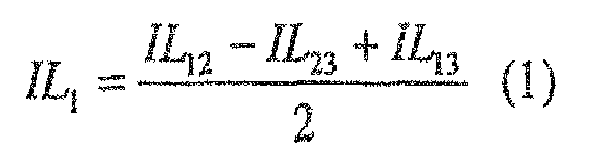


- While the example illustrated by equations (1) through (4) measures a group of four RF cables, the method can be applied to any group of three or more cables. To extend the method to an arbitrary number of cables, N, the test setups of FIGs. 1-3 can be used to measure IL 12, IL 13, and IL 23. Then an insertion loss IL 3N can be measured using the setup of FIG. 4 for all remaining cable paths (where N = number of cables to be tested and IL 3N is the combined measured insertion loss of
cable 3 and cable N in series). Then insertion loss values IL 1 , IL 2, and IL 3 can be determined using equations (1), (2), and (3) above, and insertion loss value IL N can be calculated for each of the remaining cables using the following equation (where IL N is the actual insertion loss of each cable N):
Therefore this method of this invention can be easily scaled. - By using the method of this invention, only relatively short and easily obtainable RF test cables would be required. A computer controller can be used to allow the calculations to be done with a minimum of effort.
- Similar methods can be used for determining other S12 and S21 type measurements such as phase and phase match between cable paths. The invention can also be used to characterize or test systems with devices in the system paths. Such devices can include, for example, power dividers or splitters.
- In addition to RF cables, this method could be used to perform link loss tests of fiber optics cables. Short test cables have a lower failure rate as long test cables. This method could improve maintenance costs in so far as there would be fewer inaccurate results due to faulty test cables. The other S12 and S21 parameters could be tested by substituting the desired parameter for insertion loss in the preceding discussion.
- For measuring other characteristics, S, of electrical components, the equations would be modified as:


Claims (12)
- A method of measuring insertion loss in cables, the method comprising the steps of:measuring a first insertion loss IL 12 of a first circuit path including the series connection of a first cable and a second cable;measuring a second insertion loss IL 23 of a second circuit path including the series connection of the second cable and a third cable;measuring a third insertion loss IL 13 of a third circuit path including the series connection of the first cable and the third cable; andcalculating an insertion loss IL 1 of the first cable using the formula:

- The method of claim 1, further comprising the steps of:calculating an insertion loss IL 3 of the third cable using the formula:
 calculating an insertion loss IL 2 of the second cable using the formula:
- The method of claim 2, further comprising the steps of:measuring a fourth insertion loss IL 34 of a fourth circuit path including the series connection of the third cable and a fourth cable; andcalculating an insertion loss IL 4 of the fourth cable using the formula:

- The method of claim 2, further comprising the steps of: measuring an nth insertion loss IL 3n of an nth circuit path including the series connection of the third cable and an nth cable; and
calculating an insertion loss IL n of the nth cable using the formula:
- The method of claim 1, wherein each of the cables comprises:an electrical cable.
- The method of claim 1, wherein each of the cables comprises:a fiber optic cable.
- A method of measuring characteristics of electrical components, the method comprising the steps of:measuring a first characteristic S12 of a first circuit path including the series connection of a first electrical component and a second electrical component;measuring a second characteristic S 23 of a second circuit path including the series connection of the second electrical component and a third electrical component;measuring a third characteristic S 13 of a third circuit path including the series connection of the first electrical component and the third electrical component; andcalculating a characteristic S1 of the first electrical component using the formula:

- The method of claim 7, further comprising the steps of:calculating a characteristic S 3 of the third electrical component using the formula:
 calculating a characteristic S2 of the second electrical component using the formula:
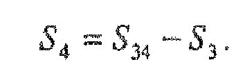
- The method of claim 8, further comprising the steps of:measuring a fourth characteristic S 34 of a fourth circuit path including the series connection of the third electrical component and a fourth electrical component; andcalculating a characteristic S 4 of the fourth electrical component using the formula:
- The method of claim 8, further comprising the steps of:measuring an nth characteristic S3n of an nth circuit path including the series connection of the third electrical component and an nth electrical component; andcalculating a characteristic Sn of the nth electrical component using the formula:

- The method of claim 7, wherein each of the electrical components comprises:an electrical cable.
- The method of claim 7, wherein each of the electrical components comprises:a fiber optic cable.
Applications Claiming Priority (1)
| Application Number | Priority Date | Filing Date | Title |
|---|---|---|---|
| US11/078,804 US7130032B2 (en) | 2005-03-11 | 2005-03-11 | Alternate test method for RF cable testing to avoid long test cables |
Publications (1)
| Publication Number | Publication Date |
|---|---|
| EP1701172A1 true EP1701172A1 (en) | 2006-09-13 |
Family
ID=36406594
Family Applications (1)
| Application Number | Title | Priority Date | Filing Date |
|---|---|---|---|
| EP06110070A Withdrawn EP1701172A1 (en) | 2005-03-11 | 2006-02-16 | RF cable testing |
Country Status (6)
| Country | Link |
|---|---|
| US (1) | US7130032B2 (en) |
| EP (1) | EP1701172A1 (en) |
| JP (1) | JP2006250931A (en) |
| CN (1) | CN1831544A (en) |
| AU (1) | AU2006200770A1 (en) |
| IL (1) | IL173721A (en) |
Cited By (2)
| Publication number | Priority date | Publication date | Assignee | Title |
|---|---|---|---|---|
| CN101159777B (en) * | 2007-11-09 | 2011-02-09 | 华为技术有限公司 | Route measuring method and device |
| CN105021933A (en) * | 2015-08-19 | 2015-11-04 | 江苏省电力公司苏州供电公司 | Relay protection high-frequency channel electric power equipment tester |
Families Citing this family (8)
| Publication number | Priority date | Publication date | Assignee | Title |
|---|---|---|---|---|
| CN101373198B (en) * | 2007-08-20 | 2011-03-16 | 电信科学技术第五研究所 | Cable test bus and switch matrix circuit |
| CN102539936B (en) * | 2010-12-13 | 2015-12-02 | 富士康(昆山)电脑接插件有限公司 | Measure the method for decay |
| WO2015134540A1 (en) * | 2014-03-04 | 2015-09-11 | Black Diamond Video | Apparatuses, methods, and systems for troubleshooting multimedia network communication systems |
| US11022638B2 (en) | 2018-04-04 | 2021-06-01 | Fluke Corporation | Testing shield continuity of a cable or cabling installation using common mode insertion loss |
| CN108646097A (en) * | 2018-04-24 | 2018-10-12 | 四川斐讯信息技术有限公司 | A kind of insertion loss test method and system |
| CN108919057B (en) * | 2018-08-07 | 2020-06-16 | 哈尔滨工业大学 | A method for handling the problem of insertion loss in cable fault diagnosis |
| CN114706718B (en) * | 2022-03-31 | 2023-12-08 | 浪潮(山东)计算机科技有限公司 | A PCIe signal integrity verification method, device, equipment and medium |
| CN117590123B (en) * | 2023-11-22 | 2025-02-28 | 中科可控信息产业有限公司 | A cable testing method, device, equipment and medium |
Citations (3)
| Publication number | Priority date | Publication date | Assignee | Title |
|---|---|---|---|---|
| US5646541A (en) * | 1994-03-24 | 1997-07-08 | Hewlett-Packard Company | Apparatus and method for measuring circuit network |
| US5978449A (en) * | 1997-04-28 | 1999-11-02 | Nynex Science & Technologies, Inc. | Qualifying telephone line for digital transmission service |
| US6417672B1 (en) * | 1999-04-21 | 2002-07-09 | Sunrise Telecom, Inc. | Detection of bridge tap using frequency domain analysis |
Family Cites Families (23)
| Publication number | Priority date | Publication date | Assignee | Title |
|---|---|---|---|---|
| US3101354A (en) * | 1960-11-16 | 1963-08-20 | Roussel Uclaf | Process for the preparation of 19-nortestosterone and compounds used in this process |
| US3104354A (en) | 1961-08-31 | 1963-09-17 | Weinschel Eng Co Inc | High-frequency insertion loss test system including coupled attenuators |
| US4219770A (en) * | 1979-01-11 | 1980-08-26 | Weinschel Engineering Co., Inc. | Insertion loss and phase shift measurement system and method |
| SU1742615A1 (en) * | 1987-05-05 | 1992-06-23 | Центральный научно-исследовательский геологоразведочный институт цветных и благородных металлов | Method for testing state of long object and device |
| US5128619A (en) * | 1989-04-03 | 1992-07-07 | Bjork Roger A | System and method of determining cable characteristics |
| JPH05267415A (en) * | 1992-03-18 | 1993-10-15 | Fujitsu Ltd | Semiconductor device |
| US5821760A (en) * | 1996-07-31 | 1998-10-13 | Fluke Corporation | Method and apparatus for measuring near-end cross-talk in patch cords |
| DE69801979T2 (en) * | 1998-07-15 | 2002-04-04 | Agilent Technologies, Inc. (N.D.Ges.D.Staates Delaware) | Optical loss measurement |
| US6529844B1 (en) * | 1998-09-02 | 2003-03-04 | Anritsu Company | Vector network measurement system |
| FR2790096B1 (en) * | 1999-02-18 | 2001-04-13 | St Microelectronics Sa | LOW LOSS ELEMENTARY STANDARD STRUCTURE FOR THE CALIBRATION OF AN INTEGRATED CIRCUIT PROBE |
| US6259256B1 (en) * | 1999-03-01 | 2001-07-10 | Nordx/Cdt, Inc. | Cable testing apparatus |
| US6256377B1 (en) * | 1999-05-25 | 2001-07-03 | Adtran, Inc. | Loop loss measurement and reporting mechanism for digital data services telephone channel equipment |
| US6816575B2 (en) * | 1999-12-09 | 2004-11-09 | Harris Corporation | Single ended loop loss measurement by frequency domain reflectometry-based signal processing |
| GB0005227D0 (en) * | 2000-03-03 | 2000-04-26 | Teradyne Inc | Technique for estimatio of insertion loss |
| ATE327517T1 (en) * | 2000-06-16 | 2006-06-15 | T Mobile Deutschland Gmbh | METHOD FOR FAULT LOCATION MEASUREMENT IN HIGH-FREQUENCY CABLES AND LINES |
| GB2365253B (en) * | 2000-07-19 | 2004-06-16 | Teradyne Inc | Method of performing insertion loss estimation |
| JP2004512504A (en) * | 2000-09-18 | 2004-04-22 | アジレント・テクノロジーズ・インク | Method and apparatus for linear identification of multi-terminal unbalanced or balanced devices |
| US6437578B1 (en) * | 2000-11-14 | 2002-08-20 | Tektronix, Inc. | Cable loss correction of distance to fault and time domain reflectometer measurements |
| US6661237B2 (en) * | 2001-09-26 | 2003-12-09 | Northrop Grumman Corporation | Smart AWA |
| US6826258B2 (en) * | 2002-06-20 | 2004-11-30 | Teradyne, Inc. | System and method for pre-qualification of telephone lines for DSL service using an average loop loss |
| US6954076B2 (en) * | 2002-09-06 | 2005-10-11 | Northrop Grumman Corporation | Aircraft multi-function wire and insulation tester |
| US7002355B2 (en) * | 2003-01-10 | 2006-02-21 | Panduit Corp. | Apparatus and method for communications testing |
| US7034548B2 (en) * | 2003-04-11 | 2006-04-25 | Agilent Technologies, Inc. | Balanced device characterization including test system calibration |
-
2005
- 2005-03-11 US US11/078,804 patent/US7130032B2/en not_active Expired - Lifetime
-
2006
- 2006-02-14 IL IL173721A patent/IL173721A/en not_active IP Right Cessation
- 2006-02-16 EP EP06110070A patent/EP1701172A1/en not_active Withdrawn
- 2006-02-24 AU AU2006200770A patent/AU2006200770A1/en not_active Abandoned
- 2006-03-02 JP JP2006055678A patent/JP2006250931A/en not_active Withdrawn
- 2006-03-10 CN CNA2006100547771A patent/CN1831544A/en active Pending
Patent Citations (3)
| Publication number | Priority date | Publication date | Assignee | Title |
|---|---|---|---|---|
| US5646541A (en) * | 1994-03-24 | 1997-07-08 | Hewlett-Packard Company | Apparatus and method for measuring circuit network |
| US5978449A (en) * | 1997-04-28 | 1999-11-02 | Nynex Science & Technologies, Inc. | Qualifying telephone line for digital transmission service |
| US6417672B1 (en) * | 1999-04-21 | 2002-07-09 | Sunrise Telecom, Inc. | Detection of bridge tap using frequency domain analysis |
Cited By (3)
| Publication number | Priority date | Publication date | Assignee | Title |
|---|---|---|---|---|
| CN101159777B (en) * | 2007-11-09 | 2011-02-09 | 华为技术有限公司 | Route measuring method and device |
| US8184778B2 (en) | 2007-11-09 | 2012-05-22 | Huawei Technologies Co., Ltd. | Line measurement method and measurement apparatus |
| CN105021933A (en) * | 2015-08-19 | 2015-11-04 | 江苏省电力公司苏州供电公司 | Relay protection high-frequency channel electric power equipment tester |
Also Published As
| Publication number | Publication date |
|---|---|
| US20060203227A1 (en) | 2006-09-14 |
| JP2006250931A (en) | 2006-09-21 |
| CN1831544A (en) | 2006-09-13 |
| IL173721A (en) | 2010-12-30 |
| US7130032B2 (en) | 2006-10-31 |
| AU2006200770A1 (en) | 2006-09-28 |
| IL173721A0 (en) | 2006-07-05 |
Similar Documents
| Publication | Publication Date | Title |
|---|---|---|
| KR100205676B1 (en) | Method and apparatus for measuring shear crosstalk in patch cords | |
| EP0768537B1 (en) | Pulse-based impedance measurement instrument | |
| CN112327060B (en) | Double-line double-end heavy current injection equivalent strong field continuous wave radiation effect test and system | |
| US20040251922A1 (en) | Methods and computer program products for full N-port vector network analyzer calibrations | |
| US7130032B2 (en) | Alternate test method for RF cable testing to avoid long test cables | |
| US20080195344A1 (en) | Method for determining measurement errors in scattering parameter measurements | |
| EP2853911A1 (en) | Two port vector network analyzer using de-embed probes | |
| US7235982B1 (en) | Re-calculating S-parameter error terms after modification of a calibrated port | |
| US20080238441A1 (en) | Vector Network Analyzer-Noise Figure Measurement | |
| TW202301821A (en) | System and method for compensating for power loss due to a radio frequency (rf) signal probe mismatch in conductive signal testing | |
| US10591522B2 (en) | Measurement apparatus | |
| CN105572480A (en) | Method for in-situ test of broadband transmission line parameters of double-conductor type cable | |
| CN104914390B (en) | The total timing accuracy calibrating installation of integrated circuit test system | |
| US6571187B1 (en) | Method for calibrating two port high frequency measurements | |
| US10145931B2 (en) | Tester | |
| US7026603B2 (en) | Fault locator for testing a complex optical circuit | |
| US10151822B2 (en) | Tester | |
| Ballo | Applying error correction to network analyzer measurements | |
| HUI et al. | RADIO FREQUENCY CONNECTOR INSERTION LOSS MEASURED FROM 300 kHz UNTIL 8.5 GHZ BY USING NETWORK ANALYZER AND MECHANICAL CALIBRATION KITS | |
| JP2005099038A (en) | Electronic calibration apparatus and method | |
| Skinner et al. | Benchmarking electronic calibration of USB-enabled network analysers | |
| Yates | RF Switch Considerations for Automatic Test Equipment Making Vector Measurements | |
| JP2023513147A (en) | Altimeter test apparatus and method | |
| Srinivasan et al. | Online RF checkers for diagnosing multi-gigahertz automatic test boards on low cost ATE platforms | |
| Glock et al. | Measurement of HOM-Propagation through Cavity Chains in Terms of S-Parameters |
Legal Events
| Date | Code | Title | Description |
|---|---|---|---|
| PUAI | Public reference made under article 153(3) epc to a published international application that has entered the european phase |
Free format text: ORIGINAL CODE: 0009012 |
|
| 17P | Request for examination filed |
Effective date: 20060216 |
|
| AK | Designated contracting states |
Kind code of ref document: A1 Designated state(s): AT BE BG CH CY CZ DE DK EE ES FI FR GB GR HU IE IS IT LI LT LU LV MC NL PL PT RO SE SI SK TR |
|
| AX | Request for extension of the european patent |
Extension state: AL BA HR MK YU |
|
| 17Q | First examination report despatched |
Effective date: 20061123 |
|
| AKX | Designation fees paid |
Designated state(s): AT BE BG CH CY CZ DE DK EE ES FI FR GB GR HU IE IS IT LI LT LU LV MC NL PL PT RO SE SI SK TR |
|
| RAP1 | Party data changed (applicant data changed or rights of an application transferred) |
Owner name: NORTHROP GRUMMAN SYSTEMS CORPORATION |
|
| STAA | Information on the status of an ep patent application or granted ep patent |
Free format text: STATUS: THE APPLICATION IS DEEMED TO BE WITHDRAWN |
|
| 18D | Application deemed to be withdrawn |
Effective date: 20110901 |