EP1701107A1 - Connecting element for a ventilation duct system and assembly and methods concerning the same - Google Patents
Connecting element for a ventilation duct system and assembly and methods concerning the same Download PDFInfo
- Publication number
- EP1701107A1 EP1701107A1 EP05003711A EP05003711A EP1701107A1 EP 1701107 A1 EP1701107 A1 EP 1701107A1 EP 05003711 A EP05003711 A EP 05003711A EP 05003711 A EP05003711 A EP 05003711A EP 1701107 A1 EP1701107 A1 EP 1701107A1
- Authority
- EP
- European Patent Office
- Prior art keywords
- connecting element
- panel
- sealing device
- panel element
- projection
- Prior art date
- Legal status (The legal status is an assumption and is not a legal conclusion. Google has not performed a legal analysis and makes no representation as to the accuracy of the status listed.)
- Granted
Links
- 238000009423 ventilation Methods 0.000 title claims abstract description 47
- 238000000034 method Methods 0.000 title claims description 25
- 238000007789 sealing Methods 0.000 claims abstract description 73
- 239000011324 bead Substances 0.000 claims description 27
- 239000002184 metal Substances 0.000 claims description 10
- 229910052751 metal Inorganic materials 0.000 claims description 10
- 239000013013 elastic material Substances 0.000 claims description 4
- 238000003466 welding Methods 0.000 description 12
- 238000009434 installation Methods 0.000 description 11
- 239000000463 material Substances 0.000 description 9
- 238000004519 manufacturing process Methods 0.000 description 6
- 239000004033 plastic Substances 0.000 description 4
- 238000004140 cleaning Methods 0.000 description 3
- 239000003562 lightweight material Substances 0.000 description 3
- 230000008569 process Effects 0.000 description 3
- 230000008439 repair process Effects 0.000 description 3
- 229910001369 Brass Inorganic materials 0.000 description 2
- RYGMFSIKBFXOCR-UHFFFAOYSA-N Copper Chemical compound [Cu] RYGMFSIKBFXOCR-UHFFFAOYSA-N 0.000 description 2
- 239000004411 aluminium Substances 0.000 description 2
- 229910052782 aluminium Inorganic materials 0.000 description 2
- XAGFODPZIPBFFR-UHFFFAOYSA-N aluminium Chemical compound [Al] XAGFODPZIPBFFR-UHFFFAOYSA-N 0.000 description 2
- 239000010951 brass Substances 0.000 description 2
- 239000010949 copper Substances 0.000 description 2
- 229910052802 copper Inorganic materials 0.000 description 2
- 230000003247 decreasing effect Effects 0.000 description 2
- 239000000835 fiber Substances 0.000 description 2
- 238000012423 maintenance Methods 0.000 description 2
- 230000000284 resting effect Effects 0.000 description 2
- 208000027418 Wounds and injury Diseases 0.000 description 1
- 230000015572 biosynthetic process Effects 0.000 description 1
- 230000006835 compression Effects 0.000 description 1
- 238000007906 compression Methods 0.000 description 1
- 230000007797 corrosion Effects 0.000 description 1
- 238000005260 corrosion Methods 0.000 description 1
- 230000008878 coupling Effects 0.000 description 1
- 238000010168 coupling process Methods 0.000 description 1
- 238000005859 coupling reaction Methods 0.000 description 1
- 230000006378 damage Effects 0.000 description 1
- 238000006073 displacement reaction Methods 0.000 description 1
- 238000009826 distribution Methods 0.000 description 1
- 230000009977 dual effect Effects 0.000 description 1
- 230000000694 effects Effects 0.000 description 1
- 208000014674 injury Diseases 0.000 description 1
- 230000003993 interaction Effects 0.000 description 1
- 150000002739 metals Chemical class 0.000 description 1
- 238000012986 modification Methods 0.000 description 1
- 230000004048 modification Effects 0.000 description 1
- 239000003973 paint Substances 0.000 description 1
- 238000003825 pressing Methods 0.000 description 1
- 238000004381 surface treatment Methods 0.000 description 1
Images
Classifications
-
- F—MECHANICAL ENGINEERING; LIGHTING; HEATING; WEAPONS; BLASTING
- F24—HEATING; RANGES; VENTILATING
- F24F—AIR-CONDITIONING; AIR-HUMIDIFICATION; VENTILATION; USE OF AIR CURRENTS FOR SCREENING
- F24F13/00—Details common to, or for air-conditioning, air-humidification, ventilation or use of air currents for screening
- F24F13/02—Ducting arrangements
Definitions
- the present invention relates to a connecting element for a ventilation duct system, said connecting element comprising a first end being adapted for connection to a panel element and a sealing device, said panel element comprising an opening with an inner edge.
- the invention further relates to a ventilation duct assembly and methods for connecting a panel element to a ventilation duct system.
- the elements concerned are typically various pipes or ducts, but can also be, for instance, panels or similar elements forming the outlet of the ventilation system and which are typically integrated into a ceiling or wall of a room.
- a common method of connecting ventilation duct elements is by welding.
- the elements can either be welded together by the manufacturer or the welding can be performed in connection with the installation of the elements.
- welding is a time-consuming process, which furthermore requires a highly skilled welder. This is especially so when the welding has to be performed in confined spaces or awkward working positions, which may often be the case when installing ventilation systems in buildings. In such cases, it may even require two people to perform the installation, thus considerably raising the cost of the procedure.
- a known connecting device concerns the connecting of a sleeve to a plate by fitting an opening in the plate around the sleeve and subsequently mechanically fastening the plate by squeezing a compressible part, typically a rubber element, with a slidable compression ring.
- the slidable ring has to be adjusted by turning screws arranged in the ring.
- the mounting requires the turning of a number of screws while at the same time holding the plate in place. This procedure may be difficult, possibly requiring the coordinated efforts of two people, and is certainly time consuming. These factors all contribute to raising the cost of installation of the ventilation duct system.
- Ventil duct systems are usually manufactured in a location other than the place of installation, it is desirable to achieve a system with few and easily transportable separate parts. It may thus be advantageous to assemble some of the components at the installation site to avoid transportation of large and unhandy assembled units. Such on-site assembly further increases the demands for easy assembly in order to minimize the skill requirements of the installation crew.
- the sealing device in a mounted position is adapted to fixate the panel element in relation to the connecting element so that the panel element is held in a secure position, and essentially preventing air flow between the inner edge of the panel element and the connecting element.
- the panel. element may be securely connected to the connecting element in a simple and efficient manner.
- the sealing device is arranged at the connecting element either before or after arrangement of the panel element, depending on the exact type of sealing device and panel element, and will hold the panel element in place without requiring any subsequent adjustment or manipulation. This procedure may be performed entirely without any tools or special skills, such as knowledge of welding.
- the sealing device will remain securely in place during all normal use of the ventilation duct system, it can be quite easily removed without in any way damaging the connecting element, the panel element or indeed the sealing device itself.
- the sealing device may be mounted and removed a virtually infinite number of times without loosing its sealing and fixating properties. Furthermore, the sealing device will, in a mounted position, essentially prevent air flow between the inner edge of the panel element and the connecting element. This is achieved by the sealing element effectively closing gaps between the connecting element and the inner edge of panel element. Preventing unwanted air flow in relation to a ventilation duct systems serves the dual purposes of making the system more efficient, that is minimizing the unwanted loss of energy when using the system, and reducing the noise generated by the system.
- the connecting element may comprise a first projection, such as a flange or bead, substantially at one end and an outer surface, said first projection forming an angle of approximately 90° with the outer surface and, in a mounted position, supporting the panel element and the sealing device.
- a first projection is a convenient way to support the panel element and the sealing device, and it may in a mounted position either support both directly, or optionally be in direct contact with only one of them and support the other indirectly.
- the first projection may be constructed as a part of the connecting element, and can thus be manufactured in the same process, or it may optionally be added to the connecting element subsequently, for example by welding.
- the first projection may extend circumferentially around the outer surface of the connecting element.
- a first projection extending in this way around the connecting element provides for very secure mounting of the sealing device and thus very secure fixation of the panel element.
- the first projection may extend only partially around the outer surface of the connecting element.
- a first projection which allows the panel element and/or the sealing device to be supported only in specific places around the outer surface of the connecting device may be preferable for certain types of panel elements and/or sealing devices.
- a groove may be arranged adjacent to said first projection of the connecting element and the sealing device may, in a mounted position, be arranged in said groove.
- a groove in the connecting element is a simple and inexpensive way to provide a means that may hold the sealing device in place. Other ways of achieving this, such as by employing special sealing devices, may however be envisioned and would be within the scope of the present invention.
- the groove may be formed between the first projection of the connecting element and a second projection, such as a bead or flange, arranged at a predetermined distance from the first projection. In this way, the groove may be formed in the process of manufacturing the connecting element, thus decreasing the total cost of manufacturing the connecting element.
- the second projection may extend circumferentially around the outer surface of the connecting element, thus allowing for a groove to be provided circumferentially around the connecting element for easy and secure fastening of the sealing device and panel element.
- the second projection may extend only partially around the outer surface of the connecting element. This may be preferable the case of special sealing devices and/or panel elements.
- an extension or diameter of the first protection may be larger than an extension or diameter of the second projection or vice versa.
- one of the extensions or diameters of the first projection or the second projection may be larger than an extension of the opening of the panel element and the other projection may have a smaller extension than the extension of the opening of the panel element so that the panel element may be fitted on the connecting element by mounting it over the projection having a small extension.
- the connecting element according to the present invention may be made of metal, plastic, fibre or any other material suitable for ventilation ducts. Different materials may be employed for the connecting element in different situations and according to the specific needs of a particular user.
- the connecting element may be made of a lightweight metal or a combination of lightweight materials, such as aluminium, brass, copper.
- Lightweight metals may be employed since they are easy to handle and inexpensive to transport.
- the connecting element may be manufactured in one piece from for instance sheet metal. This method for manufacturing the connecting element is inexpensive and quick, thus reducing the final cost of the connecting element.
- the connecting element may be in the shape of an essentially cylindrical or rectangular duct.
- a cylindrical or rectangular duct is meant a duct with a substantially cylindrical or rectangular cross-section. These are both common shapes for ventilation ducts, and the connecting element may preferably be made to fit in an existing system of ducts.
- the sealing device may be made of an elastic material, such as rubber or plastic.
- a sealing device of an elastic material will be easy to mount on the connecting element, since it may be expanded prior to and during mounting, and will then, when released, retract to fit tightly in place, for instance around the connecting element.
- the elasticity allows the sealing device to be squeezed in between two surfaces, such as a bead or flange and a panel element, after which the sealing device will apply pressure to both adjoining surfaces, thereby holding one or both in place.
- the sealing device may be in the form of an O-ring, that is a sealing ring with a substantially O-shaped cross-section.
- the O-ring will be particularly easy to mount on a connecting device and allows secure fixating of a panel element, since neither twisting of the O-ring around its own length axis nor displacement of the O-ring in the direction along the outer surface of the connecting element will have any negative effects.
- an O-ring provides for very good sealing of the gap between the connecting element and the panel element.
- the sealing device may be in the shape of an S-profile ring or an H-profile ring.
- S- or H-profile ring is meant a ring with a substantially S- or H-shaped cross-section. Both these shapes allow easy mounting of the sealing device on the connecting element, and also easy mounting of the panel element. Both types also ensure good sealing of the gap between the outer surface of the connecting element and the inner edge of the panel element.
- Other advantageous shapes and forms of sealing devices for use in the present invention will be evident to the skilled person.
- the invention also concern a ventilation duct assembly or kit for use at an outlet end of a ventilation duct system, said assembly or kit comprising a connecting element, a sealing device and a panel element having an opening with an inner edge.
- the sealing device in a mounted position is adapted to fixate the panel element in relation to the connecting element so that the panel element is held in a secure position, and essentially preventing air flow between the inner edge of the panel element and the connecting element. Easy distribution or transport of the assembly or kit according to invention is thus obtained due to the fact that the assembly do not need to be assembled at the manufacturer.
- the present invention also relates to one method for connecting a panel element to a ventilation duct system by means of a connecting element having a first end, said method comprising the steps of
- the present invention also relates to a second method for connecting a panel element to a ventilation duct system by means of a connecting element having a first end, said method comprising the steps of:
- the sealing device may be placed in a groove defined between a first projection, such as a flange or bead, and a second projection, such as a bead or flange, arranged at the end of the connecting device.
- a first projection such as a flange or bead
- a second projection such as a bead or flange
- the step of mounting the connecting element in relation to the ventilation duct system may be performed either before or after the placing of the panel element and sealing device depending on the type of connecting element used.
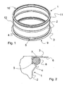
- a connecting element 1 according to an embodiment of the invention is shown schematically in perspective view in Fig. 1.
- the connecting element 1 comprises an outer surface 2, a first projection in the form of a flange 3, a second projection in the form of a bead 4 and a groove 5 between the flange 3 and the bead 4.
- the connecting element 1 has a first end 9 for receiving the panel element 6, and a second end 10 for connection to the ventilation duct system (not shown).
- the first end 9 adapted to receive the panel element 6 comprises a flange 3 and a bead 4.
- the flange 3 and bead 4 being comprised in the end 9 is meant that the flange 3 and bead 4 are closer to said first end 9 than to said second end 10.
- the present invention is not limited to the positioning of the flange 3 and bead 4 according to the preferred embodiment shown in Fig. 1.
- the flange 3 and bead 4 may be positioned with the flange 3 closer to said second end 10 than the bead 4, that is, the opposite of what is illustrated in Fig.
- a groove 5 is formed between the flange 3 and the bead 4.
- a sealing device 8 may be mounted in the groove 5 to hold the panel element 6 in place, the inner edge 7 of said panel element 6 resting on the flange 3.
- the embodiment of the present invention illustrated in Fig. 1 comprises a flange 3, a bead 4 and a groove 5, these are all optional features of the present invention, and may be excluded or only included in part.
- the connecting element comprises two flanges or two beads.
- the size and individual spacing of these optional features may vary according to the different demands posed by different ventilation systems and users.
- the second end 10 illustrated in Fig. 1 comprises sealing lips 11 and a stop bead 12.
- the second end 10 may be shaped in any way advantageous for the interaction with a ventilation duct system, and may comprise other and more features than those illustrated in Fig. 1.
- the connecting element 1 may be made of metal, plastic, fibre or any other material suitable for ventilation ducts.
- the important aspect in relation to choice of material is that the material is durable and may be made into a connecting element 1 according to the present invention. Use of other materials, which satisfy these demands, lies within the scope of the present invention.
- the connecting element 1 may be made of a lightweight metal or a combination of lightweight materials, such as aluminium, brass or copper. In addition to being easy to handle and transport, lightweight materials are typically easy to shape, and may thus facilitate the manufacture of the connecting element 1. This is particularly advantageous when making a connecting element 1 from sheet metal, and especially so when the connecting element 1 has to comprise features such as the flange 3 and/or the bead 4.
- the connecting element 1 may be manufactured in one piece, for instance from sheet metal. Typically such manufacture is accomplished by forming sheet metal into the desired shape. Such manufacture is inexpensive and quick, and furthermore allows the formation of optional features, such as the flange 3 and/or the bead 4 if these are required.
- a connecting element 1 is shown as being cylindrical in shape.
- the connecting element 1 may preferably be in the shape of an essentially cylindrical or rectangular duct- Typically, the dimensions and shape of the connecting element 1 will be adjusted to the ventilation duct system in which it is to be used.
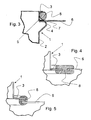
- FIG. 2 A sectional view of a connecting element 1 in mounted position is shown schematically in Fig. 2.
- the mounted connecting element 1 comprises an outer surface 2, a first projection in the form of a flange 3, a second projection in the form of a bead 4, a groove 5, a panel element 6, an inner edge 7 of the panel element 6 and a sealing device 8, here schematically shown as being slightly elastic.
- the panel element 6 illustrated in Fig. 2 has an opening fitted around the connecting element 1 and allowing the inner edge 7 of the panel element to rest on the flange 3.
- the dimensions and shape of such an opening in a panel element 6 may be such as to fit a particular connecting element 1, or optionally possibly even a range of connecting elements 1.
- the opening in the panel element 6 may advantageously be such so that the diameter of the opening is smaller than the outer diameter of the connecting element 1 at the flange 3 and larger than the outer diameter of the connecting element 1 at the bead 4. In this manner, the panel element 6 may easily be placed around the connecting element 1, with the inner edge 7 of the panel element 6 resting on the flange 3. In another preferred embodiment according to the invention, it may be the other way round, whereby the diameter of the flange 3 is smaller than the diameter of the opening of the panel element and the diameter of the bead 4 is larger.
- the sealing device 8 may be made of an elastic material, such as rubber or plastic.
- an elastic sealing device 8 may, as illustrated in Fig. 2, adjust to the surrounding materials, such as a bead 4 and a panel element 6.
- the elastic sealing device 8 will exert pressure on the materials, in this embodiment the bead 4 and the panel element 6, and will thus fixate the panel element 6 in place by pressing it towards the flange 3.
- the panel element 6 may be arranged on the other side of the sealing device 8, so that the panel element 6 is fixated between the sealing device 8 and the bead 4.
- an elastic sealing device 8 may have a cross-sectional diameter which exceeds the spatial dimensions of the groove 5 in which it is to be placed. In this manner, the elastic sealing device 8 will be squeezed together when it is placed in the groove 5 and in contact with the inner edge 7 of the panel element 6, and will thus exert pressure on the panel element 6 and thereby hold it securely in place.
- the sealing device 8 may be in the form of an O-ring. Especially an elastic O-ring would be preferable for easy mounting and secure fastening of the sealing device 8.
- the sealing device 8 according to the present invention may also be in the form of an S-profile or H-profile ring. Both types of rings may serve the purposes of sealing and fixating and are easy to mount.
- Embodiments of the present invention utilising Hand S-profile rings are illustrated in Fig. 4 and Fig. 5, respectively.
Landscapes
- Engineering & Computer Science (AREA)
- Chemical & Material Sciences (AREA)
- Combustion & Propulsion (AREA)
- Mechanical Engineering (AREA)
- General Engineering & Computer Science (AREA)
- Duct Arrangements (AREA)
Abstract
Description
- The present invention relates to a connecting element for a ventilation duct system, said connecting element comprising a first end being adapted for connection to a panel element and a sealing device, said panel element comprising an opening with an inner edge. The invention further relates to a ventilation duct assembly and methods for connecting a panel element to a ventilation duct system.
- In the field of ventilation duct systems, connecting of different elements is an often performed operation. The elements concerned are typically various pipes or ducts, but can also be, for instance, panels or similar elements forming the outlet of the ventilation system and which are typically integrated into a ceiling or wall of a room.
- A common method of connecting ventilation duct elements is by welding. The elements can either be welded together by the manufacturer or the welding can be performed in connection with the installation of the elements. In both cases, welding is a time-consuming process, which furthermore requires a highly skilled welder. This is especially so when the welding has to be performed in confined spaces or awkward working positions, which may often be the case when installing ventilation systems in buildings. In such cases, it may even require two people to perform the installation, thus considerably raising the cost of the procedure.
- A known connecting device concerns the connecting of a sleeve to a plate by fitting an opening in the plate around the sleeve and subsequently mechanically fastening the plate by squeezing a compressible part, typically a rubber element, with a slidable compression ring. The slidable ring has to be adjusted by turning screws arranged in the ring. Thus, the mounting requires the turning of a number of screws while at the same time holding the plate in place. This procedure may be difficult, possibly requiring the coordinated efforts of two people, and is certainly time consuming. These factors all contribute to raising the cost of installation of the ventilation duct system.
- However one chooses to couple elements of a ventilation duct system, it is essential to obtain a result that satisfies a number of requirements. Firstly, the final installation has to be safely mounted, with no risk of the individual elements coming apart in use of the system. Secondly, the system has to be well sealed to prevent undesirable leakage of air through gaps in the system. In addition to these basic requirements, desirable features of ventilation duct systems include few movable parts for the purpose of reducing maintenance and limiting noise from the system and a technical solution allowing easy dismantling and repair of the system.
- Since ventilation duct systems are usually manufactured in a location other than the place of installation, it is desirable to achieve a system with few and easily transportable separate parts. It may thus be advantageous to assemble some of the components at the installation site to avoid transportation of large and unhandy assembled units. Such on-site assembly further increases the demands for easy assembly in order to minimize the skill requirements of the installation crew.
- The above-mentioned known assembly methods and devices have a number of shortcomings. Welding of elements during the installation is time-consuming and requires a skilled welder. Furthermore, there is a significant risk of improper assembly, especially if the welding has to be performed in confined spaces or if no properly skilled welders are available at the site. There is also a considerable risk of damaging the ventilation duct elements during welding. For instance, surface treatments such as paints or anti-corrosive layers may be damaged or destroyed during welding, possibly leading to corrosion and decreased durability of the elements. Elements which have been welded by the manufacturer prior to delivery can be used, but are often large and bulky and thus difficult and expensive to transport. Finally, welding has the intrinsic problem of difficult dismantling, thus making repairs and adjustments difficult.
- Assembling elements together by screwing shares many disadvantages with the welding method. Thus, the method is time-consuming, difficult to perform in confined spaces and may easily lead to improper assembly. Furthermore, this method employs a large number of loose parts, namely fastening elements, such as screws, which are undesirable in a ventilation duct system due to the risk of their coming loose and of noise from improperly tightened screws. Obviously there is also a significant risk of dropping the screws during installation, and thus extra difficulties for the installation crew. Also, ventilation duct systems assembled with screws will often have the ends of screws projecting into or out from the ventilation duct. Such screw ends can obstruct cleaning, possibly tearing up and damaging cleaning equipment, and may even cause injury to the people cleaning or performing maintenance of the ventilation duct. Finally, it is important to note that the mentioned known devices for assembly all require tools, thus making installation practically impossible if the proper tools are missing.
- Based on the above-mentioned disadvantages of prior art, there is a need to provide a new device for assembly of ventilation duct elements, which can be installed in a simple yet safe and effective manner by a single person.
- There is also a need to provide a device of the kind mentioned, which can be assembled by workers unskilled in the field of ventilation and preferably without requiring tools of any kind.
- There is furthermore a need to provide a device of the kind mentioned, which easily may be dismantled for repair or adjustment.
- There is moreover a need to provide a device of the kind mentioned, which is easy to transport, has few loose parts, and complies with the many requirements of ventilation duct systems, such as being airtight, noiseless and durable.
- It is an object of the present invention to provide a connecting element for a ventilation duct system, which solves the above-mentioned disadvantages and problems of the prior art.
- The above object, together with numerous other objects, advantages and features, which will become evident from the below description, are accomplished by a solution in accordance with the present invention wherein the sealing device in a mounted position is adapted to fixate the panel element in relation to the connecting element so that the panel element is held in a secure position, and essentially preventing air flow between the inner edge of the panel element and the connecting element.
- By providing a connecting element wherein a sealing device is adapted to fixate the panel element in relation to the connecting element, it is achieved that the panel. element may be securely connected to the connecting element in a simple and efficient manner. The sealing device is arranged at the connecting element either before or after arrangement of the panel element, depending on the exact type of sealing device and panel element, and will hold the panel element in place without requiring any subsequent adjustment or manipulation. This procedure may be performed entirely without any tools or special skills, such as knowledge of welding. Likewise, although the sealing device will remain securely in place during all normal use of the ventilation duct system, it can be quite easily removed without in any way damaging the connecting element, the panel element or indeed the sealing device itself. Thus, the sealing device may be mounted and removed a virtually infinite number of times without loosing its sealing and fixating properties. Furthermore, the sealing device will, in a mounted position, essentially prevent air flow between the inner edge of the panel element and the connecting element. This is achieved by the sealing element effectively closing gaps between the connecting element and the inner edge of panel element. Preventing unwanted air flow in relation to a ventilation duct systems serves the dual purposes of making the system more efficient, that is minimizing the unwanted loss of energy when using the system, and reducing the noise generated by the system.
- Advantageously, the connecting element may comprise a first projection, such as a flange or bead, substantially at one end and an outer surface, said first projection forming an angle of approximately 90° with the outer surface and, in a mounted position, supporting the panel element and the sealing device. Such a first projection is a convenient way to support the panel element and the sealing device, and it may in a mounted position either support both directly, or optionally be in direct contact with only one of them and support the other indirectly. The first projection may be constructed as a part of the connecting element, and can thus be manufactured in the same process, or it may optionally be added to the connecting element subsequently, for example by welding.
- Preferably, the first projection may extend circumferentially around the outer surface of the connecting element. A first projection extending in this way around the connecting element provides for very secure mounting of the sealing device and thus very secure fixation of the panel element. Optionally, the first projection may extend only partially around the outer surface of the connecting element. A first projection which allows the panel element and/or the sealing device to be supported only in specific places around the outer surface of the connecting device may be preferable for certain types of panel elements and/or sealing devices.
- Advantageously, a groove may be arranged adjacent to said first projection of the connecting element and the sealing device may, in a mounted position, be arranged in said groove. A groove in the connecting element is a simple and inexpensive way to provide a means that may hold the sealing device in place. Other ways of achieving this, such as by employing special sealing devices, may however be envisioned and would be within the scope of the present invention. Preferably, the groove may be formed between the first projection of the connecting element and a second projection, such as a bead or flange, arranged at a predetermined distance from the first projection. In this way, the groove may be formed in the process of manufacturing the connecting element, thus decreasing the total cost of manufacturing the connecting element. The second projection may extend circumferentially around the outer surface of the connecting element, thus allowing for a groove to be provided circumferentially around the connecting element for easy and secure fastening of the sealing device and panel element. Optionally, the second projection may extend only partially around the outer surface of the connecting element. This may be preferable the case of special sealing devices and/or panel elements.
- In expedient manner an extension or diameter of the first protection may be larger than an extension or diameter of the second projection or vice versa.
- Furthermore, one of the extensions or diameters of the first projection or the second projection may be larger than an extension of the opening of the panel element and the other projection may have a smaller extension than the extension of the opening of the panel element so that the panel element may be fitted on the connecting element by mounting it over the projection having a small extension.
- Advantageously, the connecting element according to the present invention may be made of metal, plastic, fibre or any other material suitable for ventilation ducts. Different materials may be employed for the connecting element in different situations and according to the specific needs of a particular user.
- Preferably, the connecting element may be made of a lightweight metal or a combination of lightweight materials, such as aluminium, brass, copper. Lightweight metals may be employed since they are easy to handle and inexpensive to transport.
- Advantageously, the connecting element may be manufactured in one piece from for instance sheet metal. This method for manufacturing the connecting element is inexpensive and quick, thus reducing the final cost of the connecting element.
- Advantageously, the connecting element may be in the shape of an essentially cylindrical or rectangular duct. By a cylindrical or rectangular duct is meant a duct with a substantially cylindrical or rectangular cross-section. These are both common shapes for ventilation ducts, and the connecting element may preferably be made to fit in an existing system of ducts.
- Advantageously, the sealing device may be made of an elastic material, such as rubber or plastic. A sealing device of an elastic material will be easy to mount on the connecting element, since it may be expanded prior to and during mounting, and will then, when released, retract to fit tightly in place, for instance around the connecting element. Furthermore, the elasticity allows the sealing device to be squeezed in between two surfaces, such as a bead or flange and a panel element, after which the sealing device will apply pressure to both adjoining surfaces, thereby holding one or both in place. Preferably, the sealing device may be in the form of an O-ring, that is a sealing ring with a substantially O-shaped cross-section. The O-ring will be particularly easy to mount on a connecting device and allows secure fixating of a panel element, since neither twisting of the O-ring around its own length axis nor displacement of the O-ring in the direction along the outer surface of the connecting element will have any negative effects. Furthermore, an O-ring provides for very good sealing of the gap between the connecting element and the panel element. Optionally, the sealing device may be in the shape of an S-profile ring or an H-profile ring. By S- or H-profile ring is meant a ring with a substantially S- or H-shaped cross-section. Both these shapes allow easy mounting of the sealing device on the connecting element, and also easy mounting of the panel element. Both types also ensure good sealing of the gap between the outer surface of the connecting element and the inner edge of the panel element. Other advantageous shapes and forms of sealing devices for use in the present invention will be evident to the skilled person.
- Furthermore, the invention also concern a ventilation duct assembly or kit for use at an outlet end of a ventilation duct system, said assembly or kit comprising a connecting element, a sealing device and a panel element having an opening with an inner edge. The sealing device in a mounted position is adapted to fixate the panel element in relation to the connecting element so that the panel element is held in a secure position, and essentially preventing air flow between the inner edge of the panel element and the connecting element. Easy distribution or transport of the assembly or kit according to invention is thus obtained due to the fact that the assembly do not need to be assembled at the manufacturer.
- Additionally, the present invention also relates to one method for connecting a panel element to a ventilation duct system by means of a connecting element having a first end, said method comprising the steps of
- placing the panel element on the connecting element,
- placing a sealing device in connection with said panel element so that the panel element is held in a secure position in relation to the connecting element, and essentially preventing air flow between an inner edge of the panel element and the connecting element, and
- mounting the connecting element in relation to the ventilation duct system. Advantageously, the panel element may be placed on the connecting element at the end opposite the first end of the connecting element.
- Furthermore, the present invention also relates to a second method for connecting a panel element to a ventilation duct system by means of a connecting element having a first end, said method comprising the steps of:
- mounting the connecting element in relation to the ventilation duct system,
- placing the panel element on the connecting element, and
- placing a sealing device in connection with said panel element so that the panel element is held in a secure position in relation to the connecting element, and essentially preventing air flow between an inner edge of the panel element and the connecting element. Advantageously, the panel element may be placed on the connecting element at the first end of the connecting element.
- Preferably, the sealing device may be placed in a groove defined between a first projection, such as a flange or bead, and a second projection, such as a bead or flange, arranged at the end of the connecting device.
- The step of mounting the connecting element in relation to the ventilation duct system may be performed either before or after the placing of the panel element and sealing device depending on the type of connecting element used.
- The invention and its many advantages will be described in more detail below with reference to the accompanying schematic drawings, which, for the purpose of illustration, show some non-limiting embodiments and in which
- Fig. 1 shows a perspective view of the connecting element without either sealing device or panel element mounted,
- Fig. 2 shows a sectional view of a part of the connecting device with a sealing device and a panel element illustrated in mounted position,
- Fig. 3 shows a sectional view of a part of the connecting device with a sealing device and a panel element illustrated in mounted position,
- Fig. 4 shows a sectional view of a part of the connecting device with an H-profile sealing device and a panel element illustrated in mounted position, and
- Fig. 5 shows a sectional view of a part of the connecting device with an S-profile sealing device and a panel element illustrated in mounted position.
- All figures are highly schematic and not necessarily to scale, and they show only parts which are necessary in order to elucidate the invention, other parts being omitted or merely suggested.
- A connecting
element 1 according to an embodiment of the invention is shown schematically in perspective view in Fig. 1. The connectingelement 1 comprises anouter surface 2, a first projection in the form of aflange 3, a second projection in the form of abead 4 and agroove 5 between theflange 3 and thebead 4. - In the embodiment illustrated in Fig. 1, the connecting
element 1 has afirst end 9 for receiving thepanel element 6, and asecond end 10 for connection to the ventilation duct system (not shown). Thefirst end 9 adapted to receive thepanel element 6 comprises aflange 3 and abead 4. By theflange 3 andbead 4 being comprised in theend 9 is meant that theflange 3 andbead 4 are closer to saidfirst end 9 than to saidsecond end 10. The present invention is not limited to the positioning of theflange 3 andbead 4 according to the preferred embodiment shown in Fig. 1. For instance, theflange 3 andbead 4 may be positioned with theflange 3 closer to saidsecond end 10 than thebead 4, that is, the opposite of what is illustrated in Fig. 1. According to the invention, agroove 5 is formed between theflange 3 and thebead 4. Asealing device 8 may be mounted in thegroove 5 to hold thepanel element 6 in place, theinner edge 7 of saidpanel element 6 resting on theflange 3. Although the embodiment of the present invention illustrated in Fig. 1 comprises aflange 3, abead 4 and agroove 5, these are all optional features of the present invention, and may be excluded or only included in part. Moreover, it is within the inventive idea that the connecting element comprises two flanges or two beads. Furthermore, the size and individual spacing of these optional features may vary according to the different demands posed by different ventilation systems and users. Thesecond end 10 illustrated in Fig. 1 comprises sealinglips 11 and astop bead 12. These features are common in the field of connecting ventilation duct elements, and allows easy coupling of thesecond end 10 of the connectingelement 1 to a ventilation duct system. However, thesecond end 10 may be shaped in any way advantageous for the interaction with a ventilation duct system, and may comprise other and more features than those illustrated in Fig. 1. - Advantageously, the connecting
element 1 may be made of metal, plastic, fibre or any other material suitable for ventilation ducts. The important aspect in relation to choice of material is that the material is durable and may be made into a connectingelement 1 according to the present invention. Use of other materials, which satisfy these demands, lies within the scope of the present invention. Preferably, the connectingelement 1 may be made of a lightweight metal or a combination of lightweight materials, such as aluminium, brass or copper. In addition to being easy to handle and transport, lightweight materials are typically easy to shape, and may thus facilitate the manufacture of the connectingelement 1. This is particularly advantageous when making a connectingelement 1 from sheet metal, and especially so when the connectingelement 1 has to comprise features such as theflange 3 and/or thebead 4. - Advantageously, the connecting
element 1 may be manufactured in one piece, for instance from sheet metal. Typically such manufacture is accomplished by forming sheet metal into the desired shape. Such manufacture is inexpensive and quick, and furthermore allows the formation of optional features, such as theflange 3 and/or thebead 4 if these are required. - In the embodiment illustrated in Fig. 1, a connecting
element 1 is shown as being cylindrical in shape. However, according to the present invention, the connectingelement 1 may preferably be in the shape of an essentially cylindrical or rectangular duct- Typically, the dimensions and shape of the connectingelement 1 will be adjusted to the ventilation duct system in which it is to be used. - A sectional view of a connecting
element 1 in mounted position is shown schematically in Fig. 2. The mounted connectingelement 1 comprises anouter surface 2, a first projection in the form of aflange 3, a second projection in the form of abead 4, agroove 5, apanel element 6, aninner edge 7 of thepanel element 6 and asealing device 8, here schematically shown as being slightly elastic. Thepanel element 6 illustrated in Fig. 2 has an opening fitted around the connectingelement 1 and allowing theinner edge 7 of the panel element to rest on theflange 3. The dimensions and shape of such an opening in apanel element 6 may be such as to fit a particular connectingelement 1, or optionally possibly even a range of connectingelements 1. In regard to the preferred embodiments of a connectingelement 1 illustrated in Fig. 1 and Fig. 2, the opening in thepanel element 6 may advantageously be such so that the diameter of the opening is smaller than the outer diameter of the connectingelement 1 at theflange 3 and larger than the outer diameter of the connectingelement 1 at thebead 4. In this manner, thepanel element 6 may easily be placed around the connectingelement 1, with theinner edge 7 of thepanel element 6 resting on theflange 3. In another preferred embodiment according to the invention, it may be the other way round, whereby the diameter of theflange 3 is smaller than the diameter of the opening of the panel element and the diameter of thebead 4 is larger. - When mounting a connecting
element 1 of the type illustrated in Fig. 2, an opening, typically in the centre of thepanel element 6, is placed around the connectingelement 1 with theinner edge 7 of thepanel element 6 in contact with theflange 3 of the connectingelement 1. Subsequently, thesealing device 8 is placed in thegroove 5. Thus, when mounted, theinner edge 7 of thepanel element 6 is positioned between theflange 3 of the connectingelement 1 and thesealing device 8. Thepanel element 6 is thereby held in place by a pressure exerted by thesealing device 8, which itself is held in place by thebead 4 on the one side and theinner edge 7 of thepanel element 6 on the other side. - Advantageously, the
sealing device 8 according to the present invention may be made of an elastic material, such as rubber or plastic. In addition to being easy to mount and, if necessary, remove, anelastic sealing device 8 may, as illustrated in Fig. 2, adjust to the surrounding materials, such as abead 4 and apanel element 6. In adjusting to these materials, theelastic sealing device 8 will exert pressure on the materials, in this embodiment thebead 4 and thepanel element 6, and will thus fixate thepanel element 6 in place by pressing it towards theflange 3. In another embodiment of the present invention, illustrated in Fig. 3, thepanel element 6 may be arranged on the other side of thesealing device 8, so that thepanel element 6 is fixated between the sealingdevice 8 and thebead 4. Preferably, anelastic sealing device 8 may have a cross-sectional diameter which exceeds the spatial dimensions of thegroove 5 in which it is to be placed. In this manner, theelastic sealing device 8 will be squeezed together when it is placed in thegroove 5 and in contact with theinner edge 7 of thepanel element 6, and will thus exert pressure on thepanel element 6 and thereby hold it securely in place. - Advantageously, the
sealing device 8 may be in the form of an O-ring. Especially an elastic O-ring would be preferable for easy mounting and secure fastening of thesealing device 8. However, thesealing device 8 according to the present invention may also be in the form of an S-profile or H-profile ring. Both types of rings may serve the purposes of sealing and fixating and are easy to mount. Embodiments of the present invention utilising Hand S-profile rings are illustrated in Fig. 4 and Fig. 5, respectively. - Although the invention above has been described in connection with preferred embodiments of the invention, it will be evident for a person skilled in the art, that several modifications are conceivable without departing from the invention as defined by the following claims.
Claims (16)
- A connecting element (1) for a ventilation duct system, said connecting element (1) comprising a first end (9) being adapted for connection to a panel element (6) and a sealing device (8), said panel element (6) comprising an opening with an inner edge (7), characterized in that the sealing device (8) in a mounted position is adapted to fixate the panel element (6) in relation to the connecting element (1) so that the panel element (6) is held in a secure position, and essentially preventing air flow between the inner edge (7) of the panel element (6) and the connecting element (1).
- A connecting element (1) as claimed in claim 1, wherein the connecting element (1) comprises a first projection (3), such as a flange, substantially at said first end (9) and an outer surface (2), said first projection (3) forming an angle of approximately 90° with said outer surface (2), whereby said first projection (3) in a mounted position supports the panel element (6) and/or the sealing device (8).
- A connecting element (1) as claimed in claim 2, wherein said first projection (3) extends circumferentially wholly or partially around the outer surface (2) of the connecting element (1).
- A connecting element (1) as claimed in claim 2 or 3, wherein a groove (5) is arranged adjacent to said first projection (3) of the connecting element (1) and wherein the sealing device (8) in a mounted position is arranged in said groove (5).
- A connecting element (1) as claimed in claims 2-4, wherein a second projection (4), such as a bead, is arranged at a predetermined distance from said first projection (3) of the connecting element (1), said groove (5) thereby being formed between the first projection (3) and the second projection (4).
- A connecting element (1) as claimed in claim 5, wherein said second projection (4) extends circumferentially wholly or partially around the outer surface (2) of the connecting element (1).
- A connecting element (1) as claimed in any one of the preceding claims, wherein the connecting element (1) is manufactured in one piece from, for example sheet metal.
- A connecting element (1) as claimed in any one of the preceding claims, wherein the connecting element (1) is in the shape of an essentially cylindrical or rectangular duct.
- A connecting element (1) as claimed in any one of the preceding claims, wherein the sealing device (8) is made of an elastic material, such as rubber.
- A connecting element (1) as claimed in any one of the preceding claims, wherein the sealing device (8) is in the form of an O-ring, an S-profile ring or an H-profile ring.
- A ventilation duct assembly for use at an outlet end of a ventilation duct system, said assembly comprising a connecting element (1) according to any one of the preceding claims, a sealing device (8) and a panel element (6) having an opening with an inner edge (7), characterized in that the sealing device (8) in a mounted position is adapted to fixate the panel element (6) in relation to the connecting element (1) so that the panel element (6) is held in a secure position, and essentially preventing air flow between the inner edge (7) of the panel element (6) and the connecting element (1).
- A method for connecting a panel element (6) to a ventilation duct system by means of a connecting element (1) having a first end according to any one of the claims 1-10, said method comprising the steps of:- placing the panel element (6) on the connecting element (1),- placing a sealing device (8) in connection with said panel element (6) so that the panel element (6) is held in a secure position in relation to the connecting element (1), and essentially preventing air flow between an inner edge (7) of the panel element (6) and the connecting element (1), and- mounting the connecting element (1) in relation to the ventilation duct system.
- A method as claimed in claim 12, wherein the panel element is placed on the connecting element at the end opposite the first end of the connecting element.
- A method for connecting a panel element (6) to a ventilation duct system by means of a connecting element (1) having a first end according to any one of the claims 1-10, said method comprising the steps of:- mounting the connecting element in relation to the ventilation duct system,- placing the panel element on the connecting element, and- placing a sealing device in connection with said panel element so that the panel element is held in a secure position in relation to the connecting element, and essentially preventing air flow between an inner edge of the panel element and the connecting element.
- A method as claimed in claim 14, wherein the panel element is placed on the connecting element at the first end of the connecting element.
- A method as claimed in claim 12 or claim 14, wherein the sealing device (8) is placed in a groove (5) defined between a first projection (3) and a second projection (4) arranged at the first end (9) of the connecting device (1).
Priority Applications (2)
| Application Number | Priority Date | Filing Date | Title |
|---|---|---|---|
| DK05003711.8T DK1701107T3 (en) | 2005-02-22 | 2005-02-22 | Connecting element to a ventilation duct system and device and methods therefor |
| EP05003711.8A EP1701107B1 (en) | 2005-02-22 | 2005-02-22 | Connecting element for a ventilation duct system and assembly and methods concerning the same |
Applications Claiming Priority (1)
| Application Number | Priority Date | Filing Date | Title |
|---|---|---|---|
| EP05003711.8A EP1701107B1 (en) | 2005-02-22 | 2005-02-22 | Connecting element for a ventilation duct system and assembly and methods concerning the same |
Publications (2)
| Publication Number | Publication Date |
|---|---|
| EP1701107A1 true EP1701107A1 (en) | 2006-09-13 |
| EP1701107B1 EP1701107B1 (en) | 2018-10-17 |
Family
ID=34933862
Family Applications (1)
| Application Number | Title | Priority Date | Filing Date |
|---|---|---|---|
| EP05003711.8A Expired - Lifetime EP1701107B1 (en) | 2005-02-22 | 2005-02-22 | Connecting element for a ventilation duct system and assembly and methods concerning the same |
Country Status (2)
| Country | Link |
|---|---|
| EP (1) | EP1701107B1 (en) |
| DK (1) | DK1701107T3 (en) |
Citations (4)
| Publication number | Priority date | Publication date | Assignee | Title |
|---|---|---|---|---|
| US2987330A (en) * | 1956-10-16 | 1961-06-06 | Robertson Co H H | Sealed pipe to pipe to wall joint |
| US3998480A (en) * | 1974-12-04 | 1976-12-21 | Twedell Jack L | Take-off fitting for low pressure non-metallic duct systems |
| EP0987380A1 (en) * | 1998-09-18 | 2000-03-22 | Ubbink B.V. | Sealing device for a roof terminal through a flat roof |
| JP2004317121A (en) * | 2004-08-18 | 2004-11-11 | Noritz Corp | Ventilation adapter, ventilation fan unit using the ventilation adapter and sealing structure of ventilation pipe for ventilation hole |
-
2005
- 2005-02-22 EP EP05003711.8A patent/EP1701107B1/en not_active Expired - Lifetime
- 2005-02-22 DK DK05003711.8T patent/DK1701107T3/en active
Patent Citations (4)
| Publication number | Priority date | Publication date | Assignee | Title |
|---|---|---|---|---|
| US2987330A (en) * | 1956-10-16 | 1961-06-06 | Robertson Co H H | Sealed pipe to pipe to wall joint |
| US3998480A (en) * | 1974-12-04 | 1976-12-21 | Twedell Jack L | Take-off fitting for low pressure non-metallic duct systems |
| EP0987380A1 (en) * | 1998-09-18 | 2000-03-22 | Ubbink B.V. | Sealing device for a roof terminal through a flat roof |
| JP2004317121A (en) * | 2004-08-18 | 2004-11-11 | Noritz Corp | Ventilation adapter, ventilation fan unit using the ventilation adapter and sealing structure of ventilation pipe for ventilation hole |
Non-Patent Citations (1)
| Title |
|---|
| PATENT ABSTRACTS OF JAPAN vol. 2003, no. 12 5 December 2003 (2003-12-05) * |
Also Published As
| Publication number | Publication date |
|---|---|
| DK1701107T3 (en) | 2019-02-04 |
| EP1701107B1 (en) | 2018-10-17 |
Similar Documents
| Publication | Publication Date | Title |
|---|---|---|
| CN103635730B (en) | The method and apparatus hanging pipeline by the corner elements of insertion | |
| US10465370B2 (en) | Pipe connector | |
| US10557253B2 (en) | Mounting devices and methods for exterior faucets and lines | |
| US8936280B2 (en) | Saddle tap connection and installation device | |
| CN211257827U (en) | Easy-to-install reserved hole casing | |
| US10077902B2 (en) | Adapter for a flue gas outlet | |
| US20080014860A1 (en) | Method and apparatus for eliminating register boxes, improving penetration sealing, improving airflow and reducing the labor costs to install ceiling registers | |
| CN214019018U (en) | Fire-fighting pipeline installation system | |
| US5551414A (en) | Seal and installation improvements | |
| JP5476009B2 (en) | Tubular universal joint | |
| EP1701107B1 (en) | Connecting element for a ventilation duct system and assembly and methods concerning the same | |
| CN103307717A (en) | Air duct with improved structure for air conditioner | |
| US6709021B2 (en) | Tubular member coupling device | |
| KR20140002466A (en) | Pulse valve light fixtures used in filtration jean connection structure and method of connection | |
| CN206689242U (en) | Flange correction device | |
| CN214469246U (en) | An air conditioning vent fixing device | |
| EP1898164A1 (en) | Connection device | |
| DE602004012953T2 (en) | VIBRATING INSULATING BUILDING SYSTEM | |
| JP2006144871A (en) | Pipe connection device | |
| JP2022153644A (en) | Connection structure of drain pipe for air conditioning equipment, and piping structure | |
| CN112610768A (en) | Double-flange limiting expansion joint | |
| CN223434912U (en) | Installation structure of flame retardant air duct | |
| US20230194084A1 (en) | Joint Seal System & Method | |
| JP2016125523A (en) | Fixture for suspension bolt | |
| JP2007146917A (en) | Connected water supplying pipe equipment |
Legal Events
| Date | Code | Title | Description |
|---|---|---|---|
| PUAI | Public reference made under article 153(3) epc to a published international application that has entered the european phase |
Free format text: ORIGINAL CODE: 0009012 |
|
| AK | Designated contracting states |
Kind code of ref document: A1 Designated state(s): AT BE BG CH CY CZ DE DK EE ES FI FR GB GR HU IE IS IT LI LT LU MC NL PL PT RO SE SI SK TR |
|
| AX | Request for extension of the european patent |
Extension state: AL BA HR LV MK YU |
|
| 17P | Request for examination filed |
Effective date: 20070313 |
|
| AKX | Designation fees paid |
Designated state(s): AT BE BG CH CY CZ DE DK EE ES FI FR GB GR HU IE IS IT LI LT LU MC NL PL PT RO SE SI SK TR |
|
| 17Q | First examination report despatched |
Effective date: 20090423 |
|
| GRAP | Despatch of communication of intention to grant a patent |
Free format text: ORIGINAL CODE: EPIDOSNIGR1 |
|
| STAA | Information on the status of an ep patent application or granted ep patent |
Free format text: STATUS: GRANT OF PATENT IS INTENDED |
|
| INTG | Intention to grant announced |
Effective date: 20180605 |
|
| GRAS | Grant fee paid |
Free format text: ORIGINAL CODE: EPIDOSNIGR3 |
|
| GRAA | (expected) grant |
Free format text: ORIGINAL CODE: 0009210 |
|
| STAA | Information on the status of an ep patent application or granted ep patent |
Free format text: STATUS: THE PATENT HAS BEEN GRANTED |
|
| AK | Designated contracting states |
Kind code of ref document: B1 Designated state(s): AT BE BG CH CY CZ DE DK EE ES FI FR GB GR HU IE IS IT LI LT LU MC NL PL PT RO SE SI SK TR |
|
| REG | Reference to a national code |
Ref country code: GB Ref legal event code: FG4D |
|
| REG | Reference to a national code |
Ref country code: CH Ref legal event code: EP |
|
| REG | Reference to a national code |
Ref country code: IE Ref legal event code: FG4D |
|
| REG | Reference to a national code |
Ref country code: DE Ref legal event code: R096 Ref document number: 602005054792 Country of ref document: DE Ref country code: AT Ref legal event code: REF Ref document number: 1054522 Country of ref document: AT Kind code of ref document: T Effective date: 20181115 |
|
| REG | Reference to a national code |
Ref country code: DK Ref legal event code: T3 Effective date: 20190128 |
|
| REG | Reference to a national code |
Ref country code: NL Ref legal event code: MP Effective date: 20181017 |
|
| REG | Reference to a national code |
Ref country code: LT Ref legal event code: MG4D |
|
| REG | Reference to a national code |
Ref country code: AT Ref legal event code: MK05 Ref document number: 1054522 Country of ref document: AT Kind code of ref document: T Effective date: 20181017 |
|
| PG25 | Lapsed in a contracting state [announced via postgrant information from national office to epo] |
Ref country code: NL Free format text: LAPSE BECAUSE OF FAILURE TO SUBMIT A TRANSLATION OF THE DESCRIPTION OR TO PAY THE FEE WITHIN THE PRESCRIBED TIME-LIMIT Effective date: 20181017 |
|
| PG25 | Lapsed in a contracting state [announced via postgrant information from national office to epo] |
Ref country code: AT Free format text: LAPSE BECAUSE OF FAILURE TO SUBMIT A TRANSLATION OF THE DESCRIPTION OR TO PAY THE FEE WITHIN THE PRESCRIBED TIME-LIMIT Effective date: 20181017 Ref country code: PL Free format text: LAPSE BECAUSE OF FAILURE TO SUBMIT A TRANSLATION OF THE DESCRIPTION OR TO PAY THE FEE WITHIN THE PRESCRIBED TIME-LIMIT Effective date: 20181017 Ref country code: FI Free format text: LAPSE BECAUSE OF FAILURE TO SUBMIT A TRANSLATION OF THE DESCRIPTION OR TO PAY THE FEE WITHIN THE PRESCRIBED TIME-LIMIT Effective date: 20181017 Ref country code: BG Free format text: LAPSE BECAUSE OF FAILURE TO SUBMIT A TRANSLATION OF THE DESCRIPTION OR TO PAY THE FEE WITHIN THE PRESCRIBED TIME-LIMIT Effective date: 20190117 Ref country code: ES Free format text: LAPSE BECAUSE OF FAILURE TO SUBMIT A TRANSLATION OF THE DESCRIPTION OR TO PAY THE FEE WITHIN THE PRESCRIBED TIME-LIMIT Effective date: 20181017 Ref country code: IS Free format text: LAPSE BECAUSE OF FAILURE TO SUBMIT A TRANSLATION OF THE DESCRIPTION OR TO PAY THE FEE WITHIN THE PRESCRIBED TIME-LIMIT Effective date: 20190217 Ref country code: LT Free format text: LAPSE BECAUSE OF FAILURE TO SUBMIT A TRANSLATION OF THE DESCRIPTION OR TO PAY THE FEE WITHIN THE PRESCRIBED TIME-LIMIT Effective date: 20181017 |
|
| PG25 | Lapsed in a contracting state [announced via postgrant information from national office to epo] |
Ref country code: GR Free format text: LAPSE BECAUSE OF FAILURE TO SUBMIT A TRANSLATION OF THE DESCRIPTION OR TO PAY THE FEE WITHIN THE PRESCRIBED TIME-LIMIT Effective date: 20190118 Ref country code: PT Free format text: LAPSE BECAUSE OF FAILURE TO SUBMIT A TRANSLATION OF THE DESCRIPTION OR TO PAY THE FEE WITHIN THE PRESCRIBED TIME-LIMIT Effective date: 20190217 Ref country code: SE Free format text: LAPSE BECAUSE OF FAILURE TO SUBMIT A TRANSLATION OF THE DESCRIPTION OR TO PAY THE FEE WITHIN THE PRESCRIBED TIME-LIMIT Effective date: 20181017 |
|
| REG | Reference to a national code |
Ref country code: DE Ref legal event code: R097 Ref document number: 602005054792 Country of ref document: DE |
|
| PG25 | Lapsed in a contracting state [announced via postgrant information from national office to epo] |
Ref country code: CZ Free format text: LAPSE BECAUSE OF FAILURE TO SUBMIT A TRANSLATION OF THE DESCRIPTION OR TO PAY THE FEE WITHIN THE PRESCRIBED TIME-LIMIT Effective date: 20181017 Ref country code: IT Free format text: LAPSE BECAUSE OF FAILURE TO SUBMIT A TRANSLATION OF THE DESCRIPTION OR TO PAY THE FEE WITHIN THE PRESCRIBED TIME-LIMIT Effective date: 20181017 |
|
| PLBE | No opposition filed within time limit |
Free format text: ORIGINAL CODE: 0009261 |
|
| STAA | Information on the status of an ep patent application or granted ep patent |
Free format text: STATUS: NO OPPOSITION FILED WITHIN TIME LIMIT |
|
| PG25 | Lapsed in a contracting state [announced via postgrant information from national office to epo] |
Ref country code: SK Free format text: LAPSE BECAUSE OF FAILURE TO SUBMIT A TRANSLATION OF THE DESCRIPTION OR TO PAY THE FEE WITHIN THE PRESCRIBED TIME-LIMIT Effective date: 20181017 Ref country code: EE Free format text: LAPSE BECAUSE OF FAILURE TO SUBMIT A TRANSLATION OF THE DESCRIPTION OR TO PAY THE FEE WITHIN THE PRESCRIBED TIME-LIMIT Effective date: 20181017 Ref country code: RO Free format text: LAPSE BECAUSE OF FAILURE TO SUBMIT A TRANSLATION OF THE DESCRIPTION OR TO PAY THE FEE WITHIN THE PRESCRIBED TIME-LIMIT Effective date: 20181017 |
|
| REG | Reference to a national code |
Ref country code: DE Ref legal event code: R119 Ref document number: 602005054792 Country of ref document: DE |
|
| 26N | No opposition filed |
Effective date: 20190718 |
|
| REG | Reference to a national code |
Ref country code: CH Ref legal event code: PL |
|
| GBPC | Gb: european patent ceased through non-payment of renewal fee |
Effective date: 20190222 |
|
| PG25 | Lapsed in a contracting state [announced via postgrant information from national office to epo] |
Ref country code: SI Free format text: LAPSE BECAUSE OF FAILURE TO SUBMIT A TRANSLATION OF THE DESCRIPTION OR TO PAY THE FEE WITHIN THE PRESCRIBED TIME-LIMIT Effective date: 20181017 Ref country code: MC Free format text: LAPSE BECAUSE OF FAILURE TO SUBMIT A TRANSLATION OF THE DESCRIPTION OR TO PAY THE FEE WITHIN THE PRESCRIBED TIME-LIMIT Effective date: 20181017 Ref country code: LU Free format text: LAPSE BECAUSE OF NON-PAYMENT OF DUE FEES Effective date: 20190222 |
|
| REG | Reference to a national code |
Ref country code: BE Ref legal event code: MM Effective date: 20190228 |
|
| REG | Reference to a national code |
Ref country code: IE Ref legal event code: MM4A |
|
| PG25 | Lapsed in a contracting state [announced via postgrant information from national office to epo] |
Ref country code: CH Free format text: LAPSE BECAUSE OF NON-PAYMENT OF DUE FEES Effective date: 20190228 Ref country code: LI Free format text: LAPSE BECAUSE OF NON-PAYMENT OF DUE FEES Effective date: 20190228 |
|
| PG25 | Lapsed in a contracting state [announced via postgrant information from national office to epo] |
Ref country code: DE Free format text: LAPSE BECAUSE OF NON-PAYMENT OF DUE FEES Effective date: 20190903 Ref country code: GB Free format text: LAPSE BECAUSE OF NON-PAYMENT OF DUE FEES Effective date: 20190222 Ref country code: IE Free format text: LAPSE BECAUSE OF NON-PAYMENT OF DUE FEES Effective date: 20190222 |
|
| PG25 | Lapsed in a contracting state [announced via postgrant information from national office to epo] |
Ref country code: FR Free format text: LAPSE BECAUSE OF NON-PAYMENT OF DUE FEES Effective date: 20190228 Ref country code: BE Free format text: LAPSE BECAUSE OF NON-PAYMENT OF DUE FEES Effective date: 20190228 |
|
| PG25 | Lapsed in a contracting state [announced via postgrant information from national office to epo] |
Ref country code: TR Free format text: LAPSE BECAUSE OF FAILURE TO SUBMIT A TRANSLATION OF THE DESCRIPTION OR TO PAY THE FEE WITHIN THE PRESCRIBED TIME-LIMIT Effective date: 20181017 |
|
| PG25 | Lapsed in a contracting state [announced via postgrant information from national office to epo] |
Ref country code: CY Free format text: LAPSE BECAUSE OF FAILURE TO SUBMIT A TRANSLATION OF THE DESCRIPTION OR TO PAY THE FEE WITHIN THE PRESCRIBED TIME-LIMIT Effective date: 20181017 |
|
| PG25 | Lapsed in a contracting state [announced via postgrant information from national office to epo] |
Ref country code: HU Free format text: LAPSE BECAUSE OF FAILURE TO SUBMIT A TRANSLATION OF THE DESCRIPTION OR TO PAY THE FEE WITHIN THE PRESCRIBED TIME-LIMIT; INVALID AB INITIO Effective date: 20050222 |
|
| PGFP | Annual fee paid to national office [announced via postgrant information from national office to epo] |
Ref country code: DK Payment date: 20230104 Year of fee payment: 19 |
|
| P01 | Opt-out of the competence of the unified patent court (upc) registered |
Effective date: 20230530 |
|
| REG | Reference to a national code |
Ref country code: DK Ref legal event code: EBP Effective date: 20240229 |
|
| PG25 | Lapsed in a contracting state [announced via postgrant information from national office to epo] |
Ref country code: DK Free format text: LAPSE BECAUSE OF NON-PAYMENT OF DUE FEES Effective date: 20240229 |
|
| PG25 | Lapsed in a contracting state [announced via postgrant information from national office to epo] |
Ref country code: DK Free format text: LAPSE BECAUSE OF NON-PAYMENT OF DUE FEES Effective date: 20240229 |