EP1701078A1 - Flame-resistant tube for braking systems. - Google Patents
Flame-resistant tube for braking systems. Download PDFInfo
- Publication number
- EP1701078A1 EP1701078A1 EP06004559A EP06004559A EP1701078A1 EP 1701078 A1 EP1701078 A1 EP 1701078A1 EP 06004559 A EP06004559 A EP 06004559A EP 06004559 A EP06004559 A EP 06004559A EP 1701078 A1 EP1701078 A1 EP 1701078A1
- Authority
- EP
- European Patent Office
- Prior art keywords
- tube
- layer
- synthetic rubber
- flame
- temperature
- Prior art date
- Legal status (The legal status is an assumption and is not a legal conclusion. Google has not performed a legal analysis and makes no representation as to the accuracy of the status listed.)
- Granted
Links
Images





Classifications
-
- B—PERFORMING OPERATIONS; TRANSPORTING
- B60—VEHICLES IN GENERAL
- B60T—VEHICLE BRAKE CONTROL SYSTEMS OR PARTS THEREOF; BRAKE CONTROL SYSTEMS OR PARTS THEREOF, IN GENERAL; ARRANGEMENT OF BRAKING ELEMENTS ON VEHICLES IN GENERAL; PORTABLE DEVICES FOR PREVENTING UNWANTED MOVEMENT OF VEHICLES; VEHICLE MODIFICATIONS TO FACILITATE COOLING OF BRAKES
- B60T17/00—Component parts, details, or accessories of power brake systems not covered by groups B60T8/00, B60T13/00 or B60T15/00, or presenting other characteristic features
- B60T17/04—Arrangements of piping, valves in the piping, e.g. cut-off valves, couplings or air hoses
-
- F—MECHANICAL ENGINEERING; LIGHTING; HEATING; WEAPONS; BLASTING
- F16—ENGINEERING ELEMENTS AND UNITS; GENERAL MEASURES FOR PRODUCING AND MAINTAINING EFFECTIVE FUNCTIONING OF MACHINES OR INSTALLATIONS; THERMAL INSULATION IN GENERAL
- F16L—PIPES; JOINTS OR FITTINGS FOR PIPES; SUPPORTS FOR PIPES, CABLES OR PROTECTIVE TUBING; MEANS FOR THERMAL INSULATION IN GENERAL
- F16L11/00—Hoses, i.e. flexible pipes
- F16L11/04—Hoses, i.e. flexible pipes made of rubber or flexible plastics
- F16L11/08—Hoses, i.e. flexible pipes made of rubber or flexible plastics with reinforcements embedded in the wall
- F16L11/081—Hoses, i.e. flexible pipes made of rubber or flexible plastics with reinforcements embedded in the wall comprising one or more layers of a helically wound cord or wire
- F16L11/083—Hoses, i.e. flexible pipes made of rubber or flexible plastics with reinforcements embedded in the wall comprising one or more layers of a helically wound cord or wire three or more layers
-
- F—MECHANICAL ENGINEERING; LIGHTING; HEATING; WEAPONS; BLASTING
- F16—ENGINEERING ELEMENTS AND UNITS; GENERAL MEASURES FOR PRODUCING AND MAINTAINING EFFECTIVE FUNCTIONING OF MACHINES OR INSTALLATIONS; THERMAL INSULATION IN GENERAL
- F16L—PIPES; JOINTS OR FITTINGS FOR PIPES; SUPPORTS FOR PIPES, CABLES OR PROTECTIVE TUBING; MEANS FOR THERMAL INSULATION IN GENERAL
- F16L57/00—Protection of pipes or objects of similar shape against external or internal damage or wear
- F16L57/04—Protection of pipes or objects of similar shape against external or internal damage or wear against fire or other external sources of extreme heat
-
- Y—GENERAL TAGGING OF NEW TECHNOLOGICAL DEVELOPMENTS; GENERAL TAGGING OF CROSS-SECTIONAL TECHNOLOGIES SPANNING OVER SEVERAL SECTIONS OF THE IPC; TECHNICAL SUBJECTS COVERED BY FORMER USPC CROSS-REFERENCE ART COLLECTIONS [XRACs] AND DIGESTS
- Y10—TECHNICAL SUBJECTS COVERED BY FORMER USPC
- Y10T—TECHNICAL SUBJECTS COVERED BY FORMER US CLASSIFICATION
- Y10T428/00—Stock material or miscellaneous articles
- Y10T428/13—Hollow or container type article [e.g., tube, vase, etc.]
- Y10T428/1352—Polymer or resin containing [i.e., natural or synthetic]
- Y10T428/1362—Textile, fabric, cloth, or pile containing [e.g., web, net, woven, knitted, mesh, nonwoven, matted, etc.]
-
- Y—GENERAL TAGGING OF NEW TECHNOLOGICAL DEVELOPMENTS; GENERAL TAGGING OF CROSS-SECTIONAL TECHNOLOGIES SPANNING OVER SEVERAL SECTIONS OF THE IPC; TECHNICAL SUBJECTS COVERED BY FORMER USPC CROSS-REFERENCE ART COLLECTIONS [XRACs] AND DIGESTS
- Y10—TECHNICAL SUBJECTS COVERED BY FORMER USPC
- Y10T—TECHNICAL SUBJECTS COVERED BY FORMER US CLASSIFICATION
- Y10T428/00—Stock material or miscellaneous articles
- Y10T428/13—Hollow or container type article [e.g., tube, vase, etc.]
- Y10T428/1352—Polymer or resin containing [i.e., natural or synthetic]
- Y10T428/139—Open-ended, self-supporting conduit, cylinder, or tube-type article
- Y10T428/1393—Multilayer [continuous layer]
Definitions
- the present invention relates to a flame resistant tube for braking systems.
- the field of the invention is that of the ducts, generally comprising rubber flexible hoses, which are used to convey pressurized air to motor vehicle, railroad vehicle (such as railroad car and locomotive) braking systems and the like.
- Prior rubber tubes or pipes, used for conveying pressurized air to the above mentioned braking systems, have not been found as suitable to resist against high temperatures which, as frequently occurs in a free-flame condition, may also have values of 700-800°C.
- the tube In a fire event, moreover, the tube must resist, for a time as long as possible, against the mentioned temperatures, while preserving its pneumatic conveying function.
- the main object of the present invention is to provide a novel tube or hose construction, to be used in braking systems, which has a very high resistance against a free-flame condition.
- a further object of the present invention is to provide such a braking system tube which is adapted to resist, for a time as long as possible, against temperature of 700-800°C.
- a further object of the invention is to provide such a tube, which, in addition to the above mentioned flame resistant properties is also adapted to reduce the opacity and toxicity of the combustion fume emissions.
- the inventive tube provides the advantage that it can resist to a temperature up to a free-flame value, i.e. a temperature of the order of 700-800°C, for a time of at least 15 minutes, while preserving those functional properties, such as a pressure resistance up to 5 atm, which are required in a railroad field application.
- a free-flame value i.e. a temperature of the order of 700-800°C
- the tube shown in figure 1, and which has been generally indicated by the reference number 1, has been designed for use in pneumatic braking systems in general and, more specifically, in railroad car and locomotive braking systems.
- said tube 1 comprises a tube substrate 2, which comprises a smooth synthetic rubber layer.
- Said substrate 2 is coated by a plurality of high toughness reinforcement fabric elements 3, 4, 5, 6 which are overlapped onto one another and rubberized by the same material forming said substrate 2.
- the rubber layer 7 is then coated by a heat resistant material layer 8, which is preferably made of a silicon based compound, for example a glass fiber material, a silicon fiber material, a ceramics fiber material or a mixed fiber material.
- a heat resistant material layer 8 which is preferably made of a silicon based compound, for example a glass fiber material, a silicon fiber material, a ceramics fiber material or a mixed fiber material.
- the assembly is then coated by a further synthetic rubber layer 9, having the same composition as the underlying layers 2 and 7.
- the above mentioned layers 2, 7 and 9 of the tube 1 are made starting from flame resistant elastomeric synthetic compounds, according to the Class 3 AFNOR NF F16-101 and DIN 5510-2 Standards.
- the tube 1 comprises, in addition to the substrate 2, reinforcement fabric material elements 3-6, rubber layer 7 and heat resistant material layer 8, an additional synthetic rubber layer 10 and a further heat resistant material layer 11.
- the tube 1 construction is covered by an outer layer 9 made of a synthetic rubber material.
- Said additional layer 11, which is peculiar to this embodiment of the tube 1, can be made of the same material forming the underlying layer 8, or of a different material.
- the tested braking system tubes which have been custom-prepared for testing were new, i.e. not used.
- each braking system tube was clamped at a height of 18 cm above a top corner of the burner, i.e. at 34 cm above the test room floor.
- the tube was then ignited at the center thereof by a triangle burner, according to the EN 13813 Standard, and the temperature variations at given times were measured by NiCrNi thermal-elements and a measurement system supplied by the National Instruments, and electronically recorded.
- the temperature measurements were carried out within a time period of 1 second.
- the braking system tube pressure was measured, for the tests 1 and 3, by a pressure gauge "Digibar", supplied by the Company Hottinger Baldwin Messtechnik Darmstadt and, for the tests 4 and 5, by a pressure gauge of the Company Jumo (Article 9302/80085).
- the brake system tube was supported by two supporting elements, and the temperature measurement thermocouples were arranged, coupled by a wire, at the following points:
- the braking system tubes were brought to a pressure from 5.3 to 5.7 bars and the evolvement of the tests was filmed and, for safety reasons, observed through a monitor.
- the braking system tube became permeable after a period slightly larger than 16 minutes.
- the evolvement of the inner temperature curve reflects the fact that the tube continued to heat after having become permeable, even if the flame was removed. (Because of the hot air and heat radiation to the inside of the tube). Then, cooling air was been blown-in to cool the tube, thereby providing the disclosed temperature curve (figure 6).
- the tube was opened by cutting through it and analyzed after cooling. Thus, it was found that the smooth tube substrate 2 did not have any burning traces, in any of the mentioned tests 1 to 5.
- the temperature inside the tube increases on flame in a substantially linear manner up to respective end point, since the respective end temperature of the inside of the tube is herein indicated.
- the related pressure stress i.e. the inner air overpressure is also indicated.
- Table 1 avarage values and standard temperature variations, and pressure performance in related tests
- the average value of the flame temperature (on a gray background) is of about 590°C, and the tube became permeable after about 17 minutes at a tube inner temperature of 235°C.
- the flame average temperature was 560°C, and the tube inner temperature 251°C.
- the maximum flame temperature was measured at a distance of 25 cm from the right end.
- the inner tube temperature was measured at the middle of the tube and, accordingly, in the fifth test an inner tube temperature presumably excessively small was measured. This could be also deduced from the temperature curve of the diagram 6.
- Table 2 shows the data related to the tests performed at the highest flame temperature.
- Table 2 temperature average values and standard variations and pressure performance in the tests performed with the highest flame temperatures.
- Test 1 592 235 5 bars up to minute 17 (Diagram 1) (124)
- Test 4 558 251 5 bars up to minute 16 (Diagram 4) (53)
- the tested tubes are capable of resisting against a temperature stress corresponding to an average flame temperature from 560 to 710°C, under an inner pressure of 5 bars, for at least 15 minutes.
- the "functionality" or efficiency of the tube is held unaltered for a period of 15 minutes.
Landscapes
- Engineering & Computer Science (AREA)
- General Engineering & Computer Science (AREA)
- Mechanical Engineering (AREA)
- Transportation (AREA)
- Rigid Pipes And Flexible Pipes (AREA)
- Laminated Bodies (AREA)
- Braking Arrangements (AREA)
- Valves And Accessory Devices For Braking Systems (AREA)
- Vessels And Coating Films For Discharge Lamps (AREA)
- Resistance Heating (AREA)
Abstract
Description
- The present invention relates to a flame resistant tube for braking systems.
- The field of the invention is that of the ducts, generally comprising rubber flexible hoses, which are used to convey pressurized air to motor vehicle, railroad vehicle (such as railroad car and locomotive) braking systems and the like.
- In such an application field, it is necessary to provide the braking system with the required safety properties and efficiency, for resisting against events.
- Prior rubber tubes or pipes, used for conveying pressurized air to the above mentioned braking systems, have not been found as suitable to resist against high temperatures which, as frequently occurs in a free-flame condition, may also have values of 700-800°C.
- In a fire event, moreover, the tube must resist, for a time as long as possible, against the mentioned temperatures, while preserving its pneumatic conveying function.
- Moreover, in the railroad field, also the materials for making the mentioned rubber ducts, must meet a plurality of specific standards, related to the releasing of toxic combustion or flue fumes.
- Accordingly, the main object of the present invention is to provide a novel tube or hose construction, to be used in braking systems, which has a very high resistance against a free-flame condition.
- A further object of the present invention is to provide such a braking system tube which is adapted to resist, for a time as long as possible, against temperature of 700-800°C.
- A further object of the invention is to provide such a tube, which, in addition to the above mentioned flame resistant properties is also adapted to reduce the opacity and toxicity of the combustion fume emissions.
- According to one aspect of the present invention, the above mentioned objects, as well as yet other objects, which will become more apparent hereinafter, are achieved by a tube for braking systems, according to
claim 1. - Preferred embodiments of the inventive tube are defined in the remaining claims.
- With respect to prior braking system tubes, the inventive tube provides the advantage that it can resist to a temperature up to a free-flame value, i.e. a temperature of the order of 700-800°C, for a time of at least 15 minutes, while preserving those functional properties, such as a pressure resistance up to 5 atm, which are required in a railroad field application.
- The mentioned and other objects, advantages and characteristics of the invention will become more apparent hereinafter from the following detailed disclosure of a preferred, though not exclusive, embodiment of the tube according to the invention which is illustrated, by way of a non limitative example, in the figures of the accompanying drawings, where:
- Figure 1 shows, in a partially broken away form, a first embodiment of the tube according to the invention;
- Figure 2 is a further broken-away view showing a modified embodiment of the tube or hose shown in figure 1;
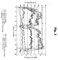
- Figures 3 to 6 show the pressurized air sealing properties of the tube, with respect to time and temperature;
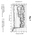
- Figure 7 shows the variation of the flame and inner temperature of the tube in tests according to figures 3 to 6, at the highest flame temperature values.
- The tube shown in figure 1, and which has been generally indicated by the
reference number 1, has been designed for use in pneumatic braking systems in general and, more specifically, in railroad car and locomotive braking systems. - More specifically, said
tube 1 comprises atube substrate 2, which comprises a smooth synthetic rubber layer. - Said
substrate 2 is coated by a plurality of high toughnessreinforcement fabric elements substrate 2. - On the top of the reinforcement fabric elements, a
synthetic rubber layer 7, made of the same material as that of thesubstrate 2, is arranged. - The
rubber layer 7 is then coated by a heatresistant material layer 8, which is preferably made of a silicon based compound, for example a glass fiber material, a silicon fiber material, a ceramics fiber material or a mixed fiber material. The assembly is then coated by a furthersynthetic rubber layer 9, having the same composition as theunderlying layers - Advantageously, according to the invention, the above mentioned
layers tube 1 are made starting from flame resistant elastomeric synthetic compounds, according to theClass 3 AFNOR NF F16-101 and DIN 5510-2 Standards. - In the modified embodiment shown in figure 2, the
tube 1 comprises, in addition to thesubstrate 2, reinforcement fabric material elements 3-6,rubber layer 7 and heatresistant material layer 8, an additionalsynthetic rubber layer 10 and a further heatresistant material layer 11. - Also in this case, the
tube 1 construction is covered by anouter layer 9 made of a synthetic rubber material. - Said
additional layer 11, which is peculiar to this embodiment of thetube 1, can be made of the same material forming theunderlying layer 8, or of a different material. - To test the flame resistant properties of the braking system tube according to the invention, specifically designed for railroad field applications, the following tests have been carrier out.
- These tests were performed to evaluate the fire performance of five railroad car braking system pressurized air tubes having the following construction (from the inside to the outside thereof):
- a
substrate 2 made of a smooth synthetic rubber material, - four reinforcement fabric material elements 3-6, overlapped onto one another and rubberized,
- a
synthetic rubber coating 7, - a temperature resistant
fiber fabric layer 8, - a
rubber layer 10 overlapped on or coating saidlayer 8, - an
additional layer 11 made of a temperature resistant fiber fabric material, and - an
outer layer 9 made of an abrasion resistant rubber material. - The tested braking system tubes, which have been custom-prepared for testing were new, i.e. not used.
- For performing a comparing with other braking system tubes, the same positions of the braking system tubes and burners have been selected.
- In the tests, each braking system tube was clamped at a height of 18 cm above a top corner of the burner, i.e. at 34 cm above the test room floor.
- The tube was then ignited at the center thereof by a triangle burner, according to the EN 13813 Standard, and the temperature variations at given times were measured by NiCrNi thermal-elements and a measurement system supplied by the National Instruments, and electronically recorded.
- The temperature measurements were carried out within a time period of 1 second.
- The braking system tube pressure was measured, for the
tests tests - The brake system tube was supported by two supporting elements, and the temperature measurement thermocouples were arranged, coupled by a wire, at the following points:
- four thermocouples under the tube (at the center two pieces and at a distance of 25 cm from the left and right ends),
- inside the tube (at the center thereof) at the top of the flame, and
- above the tube, at about its half.
- In the testing burning procedure, the braking system tubes were brought to a pressure from 5.3 to 5.7 bars and the evolvement of the tests was filmed and, for safety reasons, observed through a monitor.
- At the end of the test No. 1, it has been found that the tube, contacting the free flame, did not burst, but it became slightly permeable to air, since the temperature resistant fiber fabric material provided a stabilizing effect.
- The measurements were performed starting from an inner tube temperature of 60°C (the burner being preliminarily ignited). At minute eight, a ventilation system was turned on to suck the soot generated by the burner away and, after 17 minutes from the start of the test, the braking system tube became permeable (figure 3).
- In the test No. 2, the flame temperature was held at a lower value than that of the test No. 1, because of a different performance with respect to the flame and small modifications of the burner position. Also in the test No. 2, the braking system tube became permeable after 17 minutes (figure 4).
- In the test No. 3, the tube became permeable after a period slightly larger than 20 minutes (figure 5).
- In the test No. 4, the braking system tube became permeable after a period slightly larger than 16 minutes. The evolvement of the inner temperature curve reflects the fact that the tube continued to heat after having become permeable, even if the flame was removed. (Because of the hot air and heat radiation to the inside of the tube). Then, cooling air was been blown-in to cool the tube, thereby providing the disclosed temperature curve (figure 6).
- In the test No. 5, the tube became permeable after about 17 minutes (figure 7).
- Also in this last test, the tube heats after having removed the flame.
- However, the heating, also observed in the three previous tests, was negligible in this case, since the tube became permeable starting from this moment.
- To establish that the heating was not caused by the inner burner, the tube was opened by cutting through it and analyzed after cooling. Thus, it was found that the
smooth tube substrate 2 did not have any burning traces, in any of the mentionedtests 1 to 5. - In the following table 1, where all the time indications are related to the start of the burning in each test, the average values and standard differences of the measurement results and flame measurements and temperatures on the tube were collected.
- As it should be apparent from the previous diagrams and measurement values, the temperature inside the tube increases on flame in a substantially linear manner up to respective end point, since the respective end temperature of the inside of the tube is herein indicated.
- Moreover, the related pressure stress, i.e. the inner air overpressure is also indicated.
- From the comparatively large triangle burner and the distance between the burner and tube, it is well evident apparent that the flames flare-up whereas under the tube a variable flame temperature is generated.
-
Definition of the test Flame Temp (undex the center of the tuhe 1) Flame Temp. (under the center of the tube 2) Flame Temp. (at 25 cm from the left edge) °C Flame Temp. (at 25 cm from the right edge) °C End Temp. inside the tube °C Overpressure inside the tube, in bar Average value Average value Average value Average value Test 1 535 592 549 371 235 5 bars up to minute 17 (Diagram 1) (106) (124) (127) (91) Test 2299 292 295 134 208 5 bars up to minute 17 (Diagram 2) (50) (36) (55) (54) Test 3259 409 81 142 145 5 bars up to minute 20 (Diagram 3) (39) (53) (11) (21) Test 4558 496 346 438 251 5 bars up to minute 16 (Diagram 4) (65) (65) (41) (94) Test 5559 675 149 709 221 5 bars up to minute 17 (Diagram 5) (50) (70) (17) (70) - In the above table, the flame temperature measurement points, under the tube with the respective maximum temperatures, are shown on a gray background, since these temperatures are decisive with respect to the tube thermal stress.
- In the test No. 1, the average value of the flame temperature (on a gray background) is of about 590°C, and the tube became permeable after about 17 minutes at a tube inner temperature of 235°C.
- In the second and third tests, the tube was stressed by a more disadvantageous flame position (with respect to the tube) with smaller temperatures, and, accordingly, this data was not further considered in the following evaluations.
- In the fourth test, the flame average temperature was 560°C, and the tube inner temperature 251°C.
- In the fifth test, the maximum flame temperature was measured at a distance of 25 cm from the right end.
- The inner tube temperature was measured at the middle of the tube and, accordingly, in the fifth test an inner tube temperature presumably excessively small was measured. This could be also deduced from the temperature curve of the diagram 6.
- At larger flame temperatures in tests No. 4 and No. 5, the tube also became permeable, for an inner pressure of 5 bars, only after 16/17 minutes.
- The following Table 2 shows the data related to the tests performed at the highest flame temperature.
-
Definition of the test Flame Average Temp. °C End Temp. in the inside of the tube Overpressure in the inside of the tube, in bars Average value Test 1 592 235 5 bars up to minute 17 (Diagram 1) (124) Test 4558 251 5 bars up to minute 16 (Diagram 4) (53) Test 5709 221 5 bars up to minute 17 (Diagram 5) (70) - For flame temperatures from 560 to 710°C, the tubes, which were tested at a tube inner pressure of 5 bars, resisted against burning for a time from 16 to 17 minutes; and the inside of the tubes achieved a maximum temperature of 250°C.
- The results, which depend on the testing time at the highest flame temperature, are shown in figure 8. The diagrams of this figure clearly show the inner tube temperature increase and the related flame temperature based on the time interval. Only the highest flame temperature tests have been herein represented. From these curves it is apparent that, notwithstanding the high flame temperature, the inner tube temperature slightly increases up to a switching of the tube to a permeable condition.
- Moreover, from the above tests it is apparent that the tested tubes are capable of resisting against a temperature stress corresponding to an average flame temperature from 560 to 710°C, under an inner pressure of 5 bars, for at least 15 minutes. Thus, the "functionality" or efficiency of the tube is held unaltered for a period of 15 minutes.
Claims (7)
- A tube for pressurized air braking systems of the type comprising a synthetic rubber sublayer, at least a fabric reinforcement layer arranged above said sublayer and a further synthetic rubber layer coating said at least a reinforcement fabric layer, characterized in that said tube further comprises at least a heat resistant material layer arranged above said synthetic rubber layer and coated by a synthetic rubber outer layer.
- A tube according to claim 1, characterized in that said at least a heat resistant material layer is made of a silica based fiber material.
- A tube according to claim 2, characterized in that said silica based fiber material comprises glass fibers, silicon fibers, ceramics fibers, and mixtures thereof.
- A tube according to claim 1, characterized in that said synthetic rubber layers are made of synthetic compounds of flame resistant elastomeric materials, according to the Class 3 AFNOR NF F16-101 and DIN 5510-2 Standards.
- A tube according to claim 1, characterized in that said tube comprises moreover a further synthetic rubber layer coating said heat resistant material layer, and an additional layer also made of a heat resistant material, arranged above said further synthetic rubber layer.
- A tube according to claim 5, characterized in that said additional heat resistant material layer is made of a material like that of said heat resistant material layer.
- A tube according to claim 1, characterized in that said tube has a heat resistance temperature up to 700-800°C, for a free flame exposition of at least 15 minutes.
Applications Claiming Priority (1)
| Application Number | Priority Date | Filing Date | Title |
|---|---|---|---|
| IT000348A ITMI20050348A1 (en) | 2005-03-07 | 2005-03-07 | FLAME RESISTANT TUBE FOR BRAKING SYSTEMS |
Publications (2)
| Publication Number | Publication Date |
|---|---|
| EP1701078A1 true EP1701078A1 (en) | 2006-09-13 |
| EP1701078B1 EP1701078B1 (en) | 2010-06-02 |
Family
ID=36587243
Family Applications (1)
| Application Number | Title | Priority Date | Filing Date |
|---|---|---|---|
| EP06004559A Expired - Lifetime EP1701078B1 (en) | 2005-03-07 | 2006-03-06 | Flame-resistant tube for braking systems. |
Country Status (6)
| Country | Link |
|---|---|
| US (1) | US7363946B2 (en) |
| EP (1) | EP1701078B1 (en) |
| AT (1) | ATE470099T1 (en) |
| DE (1) | DE602006014610D1 (en) |
| ES (1) | ES2346777T3 (en) |
| IT (1) | ITMI20050348A1 (en) |
Citations (6)
| Publication number | Priority date | Publication date | Assignee | Title |
|---|---|---|---|---|
| GB1178852A (en) * | 1966-03-18 | 1970-01-21 | Mancar Trust | Fire Resistant Glass Fibre-Reinforced Pipes |
| GB1525095A (en) * | 1976-05-03 | 1978-09-20 | Schauenburg H | Hose |
| US4509559A (en) * | 1982-03-30 | 1985-04-09 | Dunlop Limited | Fire-barriers |
| US4675221A (en) * | 1978-03-08 | 1987-06-23 | Titeflex Corporation | Fire sleeve for hose |
| US20020017332A1 (en) * | 2000-07-04 | 2002-02-14 | Takashi Ishikawa | Brake hose |
| US6670004B1 (en) * | 2000-08-02 | 2003-12-30 | Saint-Gobain Performance Plastics Corporation | Laminated nylon air brake tubing |
Family Cites Families (19)
| Publication number | Priority date | Publication date | Assignee | Title |
|---|---|---|---|---|
| US3123102A (en) * | 1964-03-03 | High temperaturk resistant tubing | ||
| US3117597A (en) * | 1960-05-19 | 1964-01-14 | Porter Co Inc H K | Jet engine starter hose |
| US3053724A (en) * | 1957-01-31 | 1962-09-11 | Porter Co Inc H K | Method of splicing sections of heavy duty discharge hose |
| GB986342A (en) * | 1961-04-17 | 1965-03-17 | Btr Industries Ltd | Improvements in or relating to hose pipes |
| US3481368A (en) * | 1966-04-18 | 1969-12-02 | Goodrich Co B F | Flexible reinforced hose |
| US3866633A (en) * | 1973-06-07 | 1975-02-18 | Goodyear Tire & Rubber | Hose structure |
| US4366746A (en) * | 1974-02-14 | 1983-01-04 | Aeroquip Corporation | Pressurized hydraulic fluid system using cross-linked chlorinated polyethylene hose |
| USRE31047E (en) * | 1975-06-06 | 1982-10-05 | The Goodyear Tire & Rubber Company | Hose structure |
| US4111237A (en) * | 1976-07-12 | 1978-09-05 | General Motors Corporation | Braid reinforced flexible brake hose |
| GB1585914A (en) * | 1977-07-25 | 1981-03-11 | Goodyear Tire & Rubber | Hose |
| GB2002084B (en) * | 1977-07-28 | 1982-03-31 | Dunlop Ltd | Hose |
| US4522235A (en) * | 1980-01-10 | 1985-06-11 | The Goodyear Tire & Rubber Company | Hose structure |
| US4585035A (en) * | 1983-12-19 | 1986-04-29 | The Goodyear Tire & Rubber Company | Reinforced hose |
| JPS61206888A (en) * | 1985-03-08 | 1986-09-13 | 豊田合成株式会社 | High-pressure rubber hose |
| US5182147A (en) * | 1988-10-14 | 1993-01-26 | Dantec Ltd. | Composite hose |
| FR2649470B1 (en) * | 1989-07-05 | 1991-10-18 | Hutchinson Sa | PROTECTIVE COATING AGAINST HEAT AND FIRE FOR PIPES AND SIMILAR STRUCTURES OF ELONGATE SHAPE |
| US5507320A (en) * | 1994-10-14 | 1996-04-16 | Plumley Companies, Inc. | Hose for an automobile fuel line |
| US6926038B1 (en) * | 2001-12-31 | 2005-08-09 | Eaton Corporation | Hose structure, formulation for a rubber tube used therein and method of making the hose structure |
| DE602005009401D1 (en) * | 2004-10-26 | 2008-10-09 | Gates Corp |
-
2005
- 2005-03-07 IT IT000348A patent/ITMI20050348A1/en unknown
-
2006
- 2006-03-06 EP EP06004559A patent/EP1701078B1/en not_active Expired - Lifetime
- 2006-03-06 DE DE602006014610T patent/DE602006014610D1/en not_active Expired - Lifetime
- 2006-03-06 AT AT06004559T patent/ATE470099T1/en active
- 2006-03-06 ES ES06004559T patent/ES2346777T3/en not_active Expired - Lifetime
- 2006-03-07 US US11/369,383 patent/US7363946B2/en not_active Expired - Lifetime
Patent Citations (6)
| Publication number | Priority date | Publication date | Assignee | Title |
|---|---|---|---|---|
| GB1178852A (en) * | 1966-03-18 | 1970-01-21 | Mancar Trust | Fire Resistant Glass Fibre-Reinforced Pipes |
| GB1525095A (en) * | 1976-05-03 | 1978-09-20 | Schauenburg H | Hose |
| US4675221A (en) * | 1978-03-08 | 1987-06-23 | Titeflex Corporation | Fire sleeve for hose |
| US4509559A (en) * | 1982-03-30 | 1985-04-09 | Dunlop Limited | Fire-barriers |
| US20020017332A1 (en) * | 2000-07-04 | 2002-02-14 | Takashi Ishikawa | Brake hose |
| US6670004B1 (en) * | 2000-08-02 | 2003-12-30 | Saint-Gobain Performance Plastics Corporation | Laminated nylon air brake tubing |
Also Published As
| Publication number | Publication date |
|---|---|
| DE602006014610D1 (en) | 2010-07-15 |
| ITMI20050348A1 (en) | 2006-09-08 |
| US20060216449A1 (en) | 2006-09-28 |
| ATE470099T1 (en) | 2010-06-15 |
| US7363946B2 (en) | 2008-04-29 |
| EP1701078B1 (en) | 2010-06-02 |
| ES2346777T3 (en) | 2010-10-20 |
Similar Documents
| Publication | Publication Date | Title |
|---|---|---|
| EP1907501B1 (en) | Intumescent seal | |
| CN102301066B (en) | The two braided fabric of coating and the purposes in manufacture interconnection bellows thereof | |
| US5260125A (en) | Ceramic composite of aluminoborosilicate fibers coated with several layers | |
| WO2006047691A2 (en) | Fire resistant rubber composition and hose | |
| KR102010146B1 (en) | Silicone composition having expandable graphite and method for manufacturing gasket using the composition | |
| JP4626624B2 (en) | Heat resistant air hose | |
| EP1701078B1 (en) | Flame-resistant tube for braking systems. | |
| TW200728397A (en) | Polycarbonate composition, method of manufacture thereof and articles comprising the same | |
| CN104817844A (en) | Fireproof heat-insulation silicon rubber and preparation method thereof | |
| CA2551260C (en) | Flame-resistant tube for braking systems | |
| KR20140038395A (en) | Insulating material | |
| KR101861527B1 (en) | Fabric sheet for air duct | |
| KR20190053386A (en) | Insulation Socket for Heat Loss Prevention of Aerodynamic Heating Evaluation Device | |
| US7601426B1 (en) | Intumescent substrate coating | |
| JP2007261837A (en) | Laminated glass | |
| JP2009298127A (en) | Heat-resistant sheet with high-heat-resistant capacity and high-refractory capacity | |
| EP0742626A2 (en) | Flexible insulating hose | |
| Crowell et al. | Aerogel fabrics in advanced space suit applications | |
| JP2005186857A (en) | Vehicular heat insulating mat material | |
| US5350447A (en) | Coating for ceramic composites | |
| EP1907205B1 (en) | Multilayer hose for conveying a refrigerating fluid | |
| Hough et al. | Evaluating the fire performance of thermal pipe insulation systems by use of the vertical pipe chase apparatus | |
| JP2007507680A (en) | Air conditioning or ventilation channel | |
| RU2305036C1 (en) | Multilayer fire-protection material | |
| Plucknett et al. | Environmental aging degradation in continuous fiber ceramic composites |
Legal Events
| Date | Code | Title | Description |
|---|---|---|---|
| PUAI | Public reference made under article 153(3) epc to a published international application that has entered the european phase |
Free format text: ORIGINAL CODE: 0009012 |
|
| AK | Designated contracting states |
Kind code of ref document: A1 Designated state(s): AT BE BG CH CY CZ DE DK EE ES FI FR GB GR HU IE IS IT LI LT LU LV MC NL PL PT RO SE SI SK TR |
|
| AX | Request for extension of the european patent |
Extension state: AL BA HR MK YU |
|
| 17P | Request for examination filed |
Effective date: 20061117 |
|
| 17Q | First examination report despatched |
Effective date: 20061213 |
|
| AKX | Designation fees paid |
Designated state(s): AT BE BG CH CY CZ DE DK EE ES FI FR GB GR HU IE IS IT LI LT LU LV MC NL PL PT RO SE SI SK TR |
|
| GRAP | Despatch of communication of intention to grant a patent |
Free format text: ORIGINAL CODE: EPIDOSNIGR1 |
|
| GRAS | Grant fee paid |
Free format text: ORIGINAL CODE: EPIDOSNIGR3 |
|
| GRAA | (expected) grant |
Free format text: ORIGINAL CODE: 0009210 |
|
| AK | Designated contracting states |
Kind code of ref document: B1 Designated state(s): AT BE BG CH CY CZ DE DK EE ES FI FR GB GR HU IE IS IT LI LT LU LV MC NL PL PT RO SE SI SK TR |
|
| REG | Reference to a national code |
Ref country code: GB Ref legal event code: FG4D |
|
| REG | Reference to a national code |
Ref country code: CH Ref legal event code: EP |
|
| REG | Reference to a national code |
Ref country code: IE Ref legal event code: FG4D |
|
| REF | Corresponds to: |
Ref document number: 602006014610 Country of ref document: DE Date of ref document: 20100715 Kind code of ref document: P |
|
| REG | Reference to a national code |
Ref country code: CH Ref legal event code: NV Representative=s name: BOVARD AG PATENTANWAELTE |
|
| REG | Reference to a national code |
Ref country code: SE Ref legal event code: TRGR |
|
| REG | Reference to a national code |
Ref country code: NL Ref legal event code: VDEP Effective date: 20100602 |
|
| REG | Reference to a national code |
Ref country code: ES Ref legal event code: FG2A Ref document number: 2346777 Country of ref document: ES Kind code of ref document: T3 |
|
| PG25 | Lapsed in a contracting state [announced via postgrant information from national office to epo] |
Ref country code: LT Free format text: LAPSE BECAUSE OF FAILURE TO SUBMIT A TRANSLATION OF THE DESCRIPTION OR TO PAY THE FEE WITHIN THE PRESCRIBED TIME-LIMIT Effective date: 20100602 |
|
| LTIE | Lt: invalidation of european patent or patent extension |
Effective date: 20100602 |
|
| PG25 | Lapsed in a contracting state [announced via postgrant information from national office to epo] |
Ref country code: FI Free format text: LAPSE BECAUSE OF FAILURE TO SUBMIT A TRANSLATION OF THE DESCRIPTION OR TO PAY THE FEE WITHIN THE PRESCRIBED TIME-LIMIT Effective date: 20100602 Ref country code: LV Free format text: LAPSE BECAUSE OF FAILURE TO SUBMIT A TRANSLATION OF THE DESCRIPTION OR TO PAY THE FEE WITHIN THE PRESCRIBED TIME-LIMIT Effective date: 20100602 Ref country code: SI Free format text: LAPSE BECAUSE OF FAILURE TO SUBMIT A TRANSLATION OF THE DESCRIPTION OR TO PAY THE FEE WITHIN THE PRESCRIBED TIME-LIMIT Effective date: 20100602 |
|
| PG25 | Lapsed in a contracting state [announced via postgrant information from national office to epo] |
Ref country code: CY Free format text: LAPSE BECAUSE OF FAILURE TO SUBMIT A TRANSLATION OF THE DESCRIPTION OR TO PAY THE FEE WITHIN THE PRESCRIBED TIME-LIMIT Effective date: 20100602 Ref country code: PL Free format text: LAPSE BECAUSE OF FAILURE TO SUBMIT A TRANSLATION OF THE DESCRIPTION OR TO PAY THE FEE WITHIN THE PRESCRIBED TIME-LIMIT Effective date: 20100602 Ref country code: GR Free format text: LAPSE BECAUSE OF FAILURE TO SUBMIT A TRANSLATION OF THE DESCRIPTION OR TO PAY THE FEE WITHIN THE PRESCRIBED TIME-LIMIT Effective date: 20100903 |
|
| PG25 | Lapsed in a contracting state [announced via postgrant information from national office to epo] |
Ref country code: NL Free format text: LAPSE BECAUSE OF FAILURE TO SUBMIT A TRANSLATION OF THE DESCRIPTION OR TO PAY THE FEE WITHIN THE PRESCRIBED TIME-LIMIT Effective date: 20100602 Ref country code: EE Free format text: LAPSE BECAUSE OF FAILURE TO SUBMIT A TRANSLATION OF THE DESCRIPTION OR TO PAY THE FEE WITHIN THE PRESCRIBED TIME-LIMIT Effective date: 20100602 |
|
| PG25 | Lapsed in a contracting state [announced via postgrant information from national office to epo] |
Ref country code: RO Free format text: LAPSE BECAUSE OF FAILURE TO SUBMIT A TRANSLATION OF THE DESCRIPTION OR TO PAY THE FEE WITHIN THE PRESCRIBED TIME-LIMIT Effective date: 20100602 Ref country code: SK Free format text: LAPSE BECAUSE OF FAILURE TO SUBMIT A TRANSLATION OF THE DESCRIPTION OR TO PAY THE FEE WITHIN THE PRESCRIBED TIME-LIMIT Effective date: 20100602 Ref country code: IS Free format text: LAPSE BECAUSE OF FAILURE TO SUBMIT A TRANSLATION OF THE DESCRIPTION OR TO PAY THE FEE WITHIN THE PRESCRIBED TIME-LIMIT Effective date: 20101002 Ref country code: PT Free format text: LAPSE BECAUSE OF FAILURE TO SUBMIT A TRANSLATION OF THE DESCRIPTION OR TO PAY THE FEE WITHIN THE PRESCRIBED TIME-LIMIT Effective date: 20101004 Ref country code: BE Free format text: LAPSE BECAUSE OF FAILURE TO SUBMIT A TRANSLATION OF THE DESCRIPTION OR TO PAY THE FEE WITHIN THE PRESCRIBED TIME-LIMIT Effective date: 20100602 |
|
| REG | Reference to a national code |
Ref country code: CH Ref legal event code: PFA Owner name: IVG COLBACHINI S.P.A. Free format text: IVG COLBACHINI S.P.A.#VIA FOSSONA 132#35030 CERVARESE S. CROCE PD (IT) -TRANSFER TO- IVG COLBACHINI S.P.A.#VIA FOSSONA 132#35030 CERVARESE S. CROCE PD (IT) |
|
| PLBE | No opposition filed within time limit |
Free format text: ORIGINAL CODE: 0009261 |
|
| STAA | Information on the status of an ep patent application or granted ep patent |
Free format text: STATUS: NO OPPOSITION FILED WITHIN TIME LIMIT |
|
| PG25 | Lapsed in a contracting state [announced via postgrant information from national office to epo] |
Ref country code: DK Free format text: LAPSE BECAUSE OF FAILURE TO SUBMIT A TRANSLATION OF THE DESCRIPTION OR TO PAY THE FEE WITHIN THE PRESCRIBED TIME-LIMIT Effective date: 20100602 |
|
| 26N | No opposition filed |
Effective date: 20110303 |
|
| REG | Reference to a national code |
Ref country code: DE Ref legal event code: R097 Ref document number: 602006014610 Country of ref document: DE Effective date: 20110302 |
|
| PG25 | Lapsed in a contracting state [announced via postgrant information from national office to epo] |
Ref country code: MC Free format text: LAPSE BECAUSE OF NON-PAYMENT OF DUE FEES Effective date: 20110331 |
|
| REG | Reference to a national code |
Ref country code: IE Ref legal event code: MM4A |
|
| PG25 | Lapsed in a contracting state [announced via postgrant information from national office to epo] |
Ref country code: DE Free format text: LAPSE BECAUSE OF NON-PAYMENT OF DUE FEES Effective date: 20111001 Ref country code: IE Free format text: LAPSE BECAUSE OF NON-PAYMENT OF DUE FEES Effective date: 20110306 |
|
| PG25 | Lapsed in a contracting state [announced via postgrant information from national office to epo] |
Ref country code: LU Free format text: LAPSE BECAUSE OF NON-PAYMENT OF DUE FEES Effective date: 20110306 |
|
| PG25 | Lapsed in a contracting state [announced via postgrant information from national office to epo] |
Ref country code: TR Free format text: LAPSE BECAUSE OF FAILURE TO SUBMIT A TRANSLATION OF THE DESCRIPTION OR TO PAY THE FEE WITHIN THE PRESCRIBED TIME-LIMIT Effective date: 20100602 Ref country code: BG Free format text: LAPSE BECAUSE OF FAILURE TO SUBMIT A TRANSLATION OF THE DESCRIPTION OR TO PAY THE FEE WITHIN THE PRESCRIBED TIME-LIMIT Effective date: 20100902 |
|
| PG25 | Lapsed in a contracting state [announced via postgrant information from national office to epo] |
Ref country code: HU Free format text: LAPSE BECAUSE OF FAILURE TO SUBMIT A TRANSLATION OF THE DESCRIPTION OR TO PAY THE FEE WITHIN THE PRESCRIBED TIME-LIMIT Effective date: 20100602 |
|
| REG | Reference to a national code |
Ref country code: FR Ref legal event code: PLFP Year of fee payment: 11 |
|
| REG | Reference to a national code |
Ref country code: FR Ref legal event code: PLFP Year of fee payment: 12 |
|
| REG | Reference to a national code |
Ref country code: FR Ref legal event code: PLFP Year of fee payment: 13 |
|
| PGFP | Annual fee paid to national office [announced via postgrant information from national office to epo] |
Ref country code: SE Payment date: 20250307 Year of fee payment: 20 |
|
| PGFP | Annual fee paid to national office [announced via postgrant information from national office to epo] |
Ref country code: DE Payment date: 20250325 Year of fee payment: 20 |
|
| PGFP | Annual fee paid to national office [announced via postgrant information from national office to epo] |
Ref country code: AT Payment date: 20250318 Year of fee payment: 20 |
|
| PGFP | Annual fee paid to national office [announced via postgrant information from national office to epo] |
Ref country code: FR Payment date: 20250225 Year of fee payment: 20 Ref country code: CZ Payment date: 20250131 Year of fee payment: 20 |
|
| PGFP | Annual fee paid to national office [announced via postgrant information from national office to epo] |
Ref country code: IT Payment date: 20250205 Year of fee payment: 20 Ref country code: GB Payment date: 20250321 Year of fee payment: 20 |
|
| PGFP | Annual fee paid to national office [announced via postgrant information from national office to epo] |
Ref country code: ES Payment date: 20250402 Year of fee payment: 20 |
|
| PGFP | Annual fee paid to national office [announced via postgrant information from national office to epo] |
Ref country code: CH Payment date: 20250401 Year of fee payment: 20 |
|
| REG | Reference to a national code |
Ref country code: CH Ref legal event code: H14 Free format text: ST27 STATUS EVENT CODE: U-0-0-H10-H14 (AS PROVIDED BY THE NATIONAL OFFICE) Effective date: 20260306 Ref country code: DE Ref legal event code: R071 Ref document number: 602006014610 Country of ref document: DE |
|
| REG | Reference to a national code |
Ref country code: GB Ref legal event code: PE20 Expiry date: 20260305 |
|
| REG | Reference to a national code |
Ref country code: ES Ref legal event code: FD2A Effective date: 20260326 |
|
| PG25 | Lapsed in a contracting state [announced via postgrant information from national office to epo] |
Ref country code: ES Free format text: LAPSE BECAUSE OF EXPIRATION OF PROTECTION Effective date: 20260307 |
|
| REG | Reference to a national code |
Ref country code: AT Ref legal event code: MK07 Ref document number: 470099 Country of ref document: AT Kind code of ref document: T Effective date: 20260306 |
|
| PG25 | Lapsed in a contracting state [announced via postgrant information from national office to epo] |
Ref country code: CZ Free format text: LAPSE BECAUSE OF EXPIRATION OF PROTECTION Effective date: 20260306 |