EP1701026A1 - Method for controlling a solenoid injector - Google Patents
Method for controlling a solenoid injector Download PDFInfo
- Publication number
- EP1701026A1 EP1701026A1 EP05005166A EP05005166A EP1701026A1 EP 1701026 A1 EP1701026 A1 EP 1701026A1 EP 05005166 A EP05005166 A EP 05005166A EP 05005166 A EP05005166 A EP 05005166A EP 1701026 A1 EP1701026 A1 EP 1701026A1
- Authority
- EP
- European Patent Office
- Prior art keywords
- needle
- ferromagnetic coil
- closing position
- coil
- fluid
- Prior art date
- Legal status (The legal status is an assumption and is not a legal conclusion. Google has not performed a legal analysis and makes no representation as to the accuracy of the status listed.)
- Withdrawn
Links
- 238000000034 method Methods 0.000 title claims description 7
- 230000005294 ferromagnetic effect Effects 0.000 claims abstract description 45
- 239000012530 fluid Substances 0.000 claims abstract description 22
- 238000002347 injection Methods 0.000 claims abstract description 12
- 239000007924 injection Substances 0.000 claims abstract description 12
- 238000002485 combustion reaction Methods 0.000 description 13
- 230000005291 magnetic effect Effects 0.000 description 13
- 230000004907 flux Effects 0.000 description 10
- 239000000446 fuel Substances 0.000 description 6
- 239000000203 mixture Substances 0.000 description 2
- 239000003990 capacitor Substances 0.000 description 1
- 230000003247 decreasing effect Effects 0.000 description 1
- 238000004519 manufacturing process Methods 0.000 description 1
- 238000005259 measurement Methods 0.000 description 1
- 238000002360 preparation method Methods 0.000 description 1
- 230000000630 rising effect Effects 0.000 description 1
- 238000004088 simulation Methods 0.000 description 1
- 239000000126 substance Substances 0.000 description 1
Images


Classifications
-
- F—MECHANICAL ENGINEERING; LIGHTING; HEATING; WEAPONS; BLASTING
- F02—COMBUSTION ENGINES; HOT-GAS OR COMBUSTION-PRODUCT ENGINE PLANTS
- F02M—SUPPLYING COMBUSTION ENGINES IN GENERAL WITH COMBUSTIBLE MIXTURES OR CONSTITUENTS THEREOF
- F02M51/00—Fuel-injection apparatus characterised by being operated electrically
- F02M51/06—Injectors peculiar thereto with means directly operating the valve needle
- F02M51/061—Injectors peculiar thereto with means directly operating the valve needle using electromagnetic operating means
-
- F—MECHANICAL ENGINEERING; LIGHTING; HEATING; WEAPONS; BLASTING
- F02—COMBUSTION ENGINES; HOT-GAS OR COMBUSTION-PRODUCT ENGINE PLANTS
- F02M—SUPPLYING COMBUSTION ENGINES IN GENERAL WITH COMBUSTIBLE MIXTURES OR CONSTITUENTS THEREOF
- F02M61/00—Fuel-injectors not provided for in groups F02M39/00 - F02M57/00 or F02M67/00
- F02M61/04—Fuel-injectors not provided for in groups F02M39/00 - F02M57/00 or F02M67/00 having valves, e.g. having a plurality of valves in series
- F02M61/08—Fuel-injectors not provided for in groups F02M39/00 - F02M57/00 or F02M67/00 having valves, e.g. having a plurality of valves in series the valves opening in direction of fuel flow
Definitions
- the invention relates to a method for controlling a solenoid injector.
- the object of the invention is to create a method and a device for controlling a solenoid injector, which enables a precise dosing of small quantities of fluid.
- the invention is distinguished by a method and a respective device for controlling a solenoid injector with an actuator comprising a ferromagnetic coil.
- the actuator acts on a needle, which prevents an injection of a fluid in a closing position of the needle and otherwise enables the injection of the fluid.
- the ferromagnetic coil is energized for moving the needle out of the closing position.
- the ferromagnetic coil is de-energized until an electrical current through the coil reaches a zero value for moving the needle back into the closing position.
- a negative electrical current through the coil is controlled with respect to the electrical current of the second step for a given time.
- a remanence magnetic flux density remaining in the actuator when the electrical current through the coil reaches zero may be further reduced, which surprisingly results in a faster closing of the needle, that is a faster movement into its closing position.
- This then results in a decreased amount of fluid being at a minimum possibly dosed by the solenoid injector.
- this also results in a more precise dosing of the fluid.
- the third step may only be conducted, when the amount of fluid to be dosed by the solenoid injector is below a given threshold value.
- the third step comprises applying a voltage of opposite polarity in respect of a voltage for energizing a ferromagnetic coil in the first step.
- An injector 1 ( Figure 1) comprises a housing 3 with a recess 4.
- a needle 5 is taken in the recess 4 of the housing 3.
- the needle 5 prevents an injection of a fluid, in particular of fuel and in other positions the needle 5 enables the injection of fluid through a nozzle 7.
- a tensioning means is provided, which is preferably a spring, which is pretensioned in a way that the needle 5 rests in its closing position, where no forces or no respective high forces are being exerted by an actuator 11.
- the injector comprises the actuator 11.
- the actuator 11 comprises a ferromagnetic coil 13, which is controlled by a control device 15.
- a force is exerted on the needle 5, for example via an armature being coupled to the needle 5.
- the position of the needle 5 may be influenced and respectively the needle 5 may be moved out of its closing position or back into its closing position or being held in a given opening position in order to achieve the desired dosing of fluid through the solenoid injector 1.
- the injector 1 is provided with a fuel inlet which is preferably connected to a fluid supply of an internal combustion engine.
- the injector 1 is also preferably arranged in an internal combustion engine. It is preferably arranged in a way in the internal combustion engine, that it can dose fluid directly into a cylinder of the internal combustion engine.
- the fluid supply provides fluid under high pressure, in the case of gasoline as fluid, for example with a pressure of up to 200 bars.
- the injector may, however, also be arranged in an intake manifold, which communicates with the respective cylinders of the internal combustion engine.
- the control device 15 is provided, which may also be referred to as device for controlling the solenoid injector 1.
- the control device 15 comprises a block B1, which incorporates a premagnetizing unit.
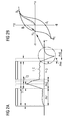
- the premagnetizing unit is designed to control a current I_C through the ferromagnetic coil 13 in a first phase PH1 ( Figure 2A) in order to premagnetize the ferromagnetic circuit, which also includes, besides the ferromagnetic coil, the armature and other ferromagnetic devices.
- a block B2 is further provided, which is designed for providing a current through the ferromagnetic coil 13 rising very quickly and resulting in a current I_C with a high amplitude, which then results in a high magnetic force moving the needle 5 away from its closing position into the opening position.
- the control is performed via the block B2 during a second phase PH2.
- the current I_C through the ferromagnetic coil 13 is again reduced to a holding current level.
- a block B4 which incorporates a hold-unit, takes over control of the current through the ferromagnetic coil 13. This is shown by the third phase PH3 in Figure 2A.
- the needle remains in its opening position and therefore fluid is dosed through the nozzle 7, preferably into a combustion chamber of a cylinder of an internal combustion engine.
- a block B6 is provided, which comprises a first closing unit.
- This first closing unit preferably comprises electronic circuitry 3 comprising a capacitor, which is used to store the energy being provided to the ferromagnetic coil 13 during the first three phases PH1-PH3. Therefore an appropriate voltage is applied to the ferromagnetic coil 13 during a fourth phase PH4, during which block B6 takes over control in order to reduce the magnetic flux density within the ferromagnetic coil 13.
- the fourth phase PH4 is terminated when the current through the ferromagnetic coil 13 has reached a zero value coming from a positive value during the first to fourth phases PH1 to PH4.
- a remanence magnetic flux density B R remains in the ferromagnetic parts of the actuator 11, which reduces the speed of the needle 5 while moving back into its closing position.
- a block B8 is provided which comprises a second closing unit. The control of the current of the ferromagnetic coil 13 is conducted via the block B8 when the fourth phase PH4 has been terminated.
- a block B12 which comprises a current measuring or determining unit for determining the current through the ferromagnetic coil 13.
- the block B8 is designed for controlling a negative electrical current through the ferromagnetic coil 13 for a given time DT.
- the control is given to the block B8, when a triggering signal TRIG is generated by a block B10 comprising a scheduling unit for determining which of the blocks B1, B2, B4, B6, B8 currently takes over control of the current through the ferromagnetic coil 13.
- the block B8 is designed to provide a voltage of opposite polarity in respect of a voltage for energizing the ferromagnetic coil 13 during the first to third phases PH1-PH3. This voltage of opposite polarity results in the negative current through the ferromagnetic coil 13 and in this way reduces the magnetic flux density B within the actuator 11.
- the given time DT is preferably chosen in a way, that the magnetic flux density B is reduced from its remanence magnetic flux density B R to a basically zero magnetic flux density B.
- the given time DT is stored in the control device and is determined before operation of the control device by way of experiments or simulations.
- the given time DT is preferably that duration of time, during which the given voltage of opposite polarity is applied to the ferromagnetic coil 13.
- the needle 5 reaches its closing position again. After that the needle 5 remains in its closing position until the next injection event is controlled.
- This time is usually significantly larger than the time for the phases PH1 to PH3. For that reason during phase PH1 the hystheresis curve between the magnetic flux density B and the magnetic field strength H is started again from the value of zero each for the magnetic flux density B and the magnetic field strength H.
- Figure 3 shows respective plots of the current I_C and the voltage V_C being applied to the ferromagnetic coil 13.
Landscapes
- Engineering & Computer Science (AREA)
- Chemical & Material Sciences (AREA)
- Combustion & Propulsion (AREA)
- Mechanical Engineering (AREA)
- General Engineering & Computer Science (AREA)
- Physics & Mathematics (AREA)
- Electromagnetism (AREA)
- Fuel-Injection Apparatus (AREA)
Abstract
A solenoid injector (1) has an actuator (11) comprising a ferromagnetic coil (13). The actuator acts on a needle (5), which prevents an injection of a fluid in a closing position of the needle (5) and otherwise enables the injection of the fluid. In a first step the ferromagnetic coil (13) is energized for moving the needle (5) out of the closing position. In a second step the ferromagnetic coil (13) is de-energized until an electrical current through the ferromagnetic coil (13) reaches a zero value for moving the needle (5) back to the closing position. In a third step a negative electrical current is controlled through the ferromagnetic coil (13) with respect to the electrical current of the second step for a given time (DT).

Description
- The invention relates to a method for controlling a solenoid injector.
- Increasingly strict regulations concerning exhaust emissions of internal combustion engines, which are located in vehicles, make it necessary to provide some measures, which reduce the exhaust emissions. One way of assessing this is to reduce the exhaust emissions produced by the internal combustion engine during the combustion process. Another way of assessing this challenge is to use exhaust after treatment systems to transform the unwanted emissions into harmless substances. For reducing the exhaust emissions created during the combustion process it is necessary to provide a very good mixture between air and fuel, which is injected by an injector. For achieving such a good mixture preparation multiple injections of fuel during one working cycle of the internal combustion engine are provided in certain engine states. This renders a precise dosing of extremely small amounts of fuel via the injector necessary. Also in very low load engine states of the engine extremely small quantities of fuel need to be dosed into the cylinder of the internal combustion engine. A precise dosing of as small as possible amounts of fluid therefore improves the engine's exhaust emission production in a positive way.
- The object of the invention is to create a method and a device for controlling a solenoid injector, which enables a precise dosing of small quantities of fluid.
- The object is achieved by the features of the independent claims. Advantageous embodiments of the invention are given in the subclaims.
- The invention is distinguished by a method and a respective device for controlling a solenoid injector with an actuator comprising a ferromagnetic coil. The actuator acts on a needle, which prevents an injection of a fluid in a closing position of the needle and otherwise enables the injection of the fluid. In a first step the ferromagnetic coil is energized for moving the needle out of the closing position. In a second step the ferromagnetic coil is de-energized until an electrical current through the coil reaches a zero value for moving the needle back into the closing position. In a third step a negative electrical current through the coil is controlled with respect to the electrical current of the second step for a given time. In that way by properly choosing the given time a remanence magnetic flux density remaining in the actuator when the electrical current through the coil reaches zero may be further reduced, which surprisingly results in a faster closing of the needle, that is a faster movement into its closing position. This then results in a decreased amount of fluid being at a minimum possibly dosed by the solenoid injector. At the same time this also results in a more precise dosing of the fluid. Preferably the third step may only be conducted, when the amount of fluid to be dosed by the solenoid injector is below a given threshold value.
- In an advantageous embodiment of the invention the third step comprises applying a voltage of opposite polarity in respect of a voltage for energizing a ferromagnetic coil in the first step. This has the advantage, that such a voltage may be controlled in a simple way.
- Exemplary embodiments of the invention are explained in the following with the aid of schematic drawings. These are as follows:
- Figure 1: a solenoid injector and a device for controlling the solenoid injector,
- Figure 2A: a current through a ferromagnetic coil of an actuator of the injector plotted over the time,
- Figure 2B: an historesis curve, and
- Figure 3: measurement signals of the current through the coil and a voltage applied to the coil plotted versus the time.
- An injector 1 (Figure 1) comprises a
housing 3 with arecess 4. A needle 5 is taken in therecess 4 of thehousing 3. In its closing position the needle 5 prevents an injection of a fluid, in particular of fuel and in other positions the needle 5 enables the injection of fluid through anozzle 7. Preferably a tensioning means is provided, which is preferably a spring, which is pretensioned in a way that the needle 5 rests in its closing position, where no forces or no respective high forces are being exerted by anactuator 11. - The injector comprises the
actuator 11. Theactuator 11 comprises aferromagnetic coil 13, which is controlled by acontrol device 15. Depending on a magnetic flux density B a force is exerted on the needle 5, for example via an armature being coupled to the needle 5. Depending on the control signals being applied to theferromagnetic coil 13 the position of the needle 5 may be influenced and respectively the needle 5 may be moved out of its closing position or back into its closing position or being held in a given opening position in order to achieve the desired dosing of fluid through the solenoid injector 1. - The injector 1 is provided with a fuel inlet which is preferably connected to a fluid supply of an internal combustion engine. The injector 1 is also preferably arranged in an internal combustion engine. It is preferably arranged in a way in the internal combustion engine, that it can dose fluid directly into a cylinder of the internal combustion engine. The fluid supply provides fluid under high pressure, in the case of gasoline as fluid, for example with a pressure of up to 200 bars. The injector may, however, also be arranged in an intake manifold, which communicates with the respective cylinders of the internal combustion engine. The
control device 15 is provided, which may also be referred to as device for controlling the solenoid injector 1. - The
control device 15 comprises a block B1, which incorporates a premagnetizing unit. The premagnetizing unit is designed to control a current I_C through theferromagnetic coil 13 in a first phase PH1 (Figure 2A) in order to premagnetize the ferromagnetic circuit, which also includes, besides the ferromagnetic coil, the armature and other ferromagnetic devices. - A block B2 is further provided, which is designed for providing a current through the
ferromagnetic coil 13 rising very quickly and resulting in a current I_C with a high amplitude, which then results in a high magnetic force moving the needle 5 away from its closing position into the opening position. The control is performed via the block B2 during a second phase PH2. At the end of the second phase PH2 the current I_C through theferromagnetic coil 13 is again reduced to a holding current level. - During controlling of the current through the
ferromagnetic coil 13 to the holding current level a block B4, which incorporates a hold-unit, takes over control of the current through theferromagnetic coil 13. This is shown by the third phase PH3 in Figure 2A. During the third phase PH3 the needle remains in its opening position and therefore fluid is dosed through thenozzle 7, preferably into a combustion chamber of a cylinder of an internal combustion engine. - At the end of the third phase PH3, it is desired to close the needle again, that means to move the needle 5 back into its closing position. A block B6 is provided, which comprises a first closing unit. This first closing unit preferably comprises
electronic circuitry 3 comprising a capacitor, which is used to store the energy being provided to theferromagnetic coil 13 during the first three phases PH1-PH3. Therefore an appropriate voltage is applied to theferromagnetic coil 13 during a fourth phase PH4, during which block B6 takes over control in order to reduce the magnetic flux density within theferromagnetic coil 13. - The fourth phase PH4 is terminated when the current through the
ferromagnetic coil 13 has reached a zero value coming from a positive value during the first to fourth phases PH1 to PH4. - When the
fourth phase PH 4 is terminated a remanence magnetic flux density BR remains in the ferromagnetic parts of theactuator 11, which reduces the speed of the needle 5 while moving back into its closing position. In order to speed up this process a block B8 is provided which comprises a second closing unit. The control of the current of theferromagnetic coil 13 is conducted via the block B8 when the fourth phase PH4 has been terminated. - In order to detect the zero crossing of the current I_C through the ferromagnetic coil a block B12 is provided, which comprises a current measuring or determining unit for determining the current through the
ferromagnetic coil 13. The block B8 is designed for controlling a negative electrical current through theferromagnetic coil 13 for a given time DT. The control is given to the block B8, when a triggering signal TRIG is generated by a block B10 comprising a scheduling unit for determining which of the blocks B1, B2, B4, B6, B8 currently takes over control of the current through theferromagnetic coil 13. - The block B8 is designed to provide a voltage of opposite polarity in respect of a voltage for energizing the
ferromagnetic coil 13 during the first to third phases PH1-PH3. This voltage of opposite polarity results in the negative current through theferromagnetic coil 13 and in this way reduces the magnetic flux density B within theactuator 11. - The given time DT is preferably chosen in a way, that the magnetic flux density B is reduced from its remanence magnetic flux density BR to a basically zero magnetic flux density B. For that purpose the given time DT is stored in the control device and is determined before operation of the control device by way of experiments or simulations.
- The given time DT is preferably that duration of time, during which the given voltage of opposite polarity is applied to the
ferromagnetic coil 13. During the fifth phase PH5 the needle 5 reaches its closing position again. After that the needle 5 remains in its closing position until the next injection event is controlled. This time is usually significantly larger than the time for the phases PH1 to PH3. For that reason during phase PH1 the hystheresis curve between the magnetic flux density B and the magnetic field strength H is started again from the value of zero each for the magnetic flux density B and the magnetic field strength H. - Figure 3 shows respective plots of the current I_C and the voltage V_C being applied to the
ferromagnetic coil 13.
Claims (3)
- Method for controlling a solenoid injector (1) with an actuator (11) comprising a ferromagnetic coil (13), the actuator (11) acting on a needle (5), which prevents an injection of a fluid in a closing position of the needle (5) and otherwise enables the injection of fluid, comprising- a first step of energizing the ferromagnetic coil (13) for moving the needle (5) out of the closing position,- second step of de-energizing the ferromagnetic coil (13) until an electrical current (I_C) through the ferromagnetic coil (13) reaches a zero value for moving the needle (5) back in the closing position and- a third step of controlling a negative electrical current through the ferromagnetic coil (13) with respect to the electrical current (I_C) of the second step for a given time (DT).
- A method according to claim 1, with the third step comprising applying a voltage of opposite polarity in respect to a voltage for energizing the ferromagnetic coil (13) in the first step.
- Device for controlling a solenoid injector (1) with an actuator (11) comprising a ferromagnetic coil (13), the actuator (11) acting on a needle (5), which prevents an injection of a fluid in a closing position of the needle (5) and otherwise enables the injection of fluid, the device being designed for- energizing in a first step the ferromagnetic coil (13) for moving the needle (5) out of the closing position,- for de-energizing the ferromagnetic coil in a second step until an electrical current through the ferromagnetic coil (13) reaches a zero value for moving the needle (5) back in the closing position,- for controlling in a third step a negative electrical current through the ferromagnetic coil (13) with respect to the electrical current of the second step for a given time.
Priority Applications (1)
| Application Number | Priority Date | Filing Date | Title |
|---|---|---|---|
| EP05005166A EP1701026A1 (en) | 2005-03-09 | 2005-03-09 | Method for controlling a solenoid injector |
Applications Claiming Priority (1)
| Application Number | Priority Date | Filing Date | Title |
|---|---|---|---|
| EP05005166A EP1701026A1 (en) | 2005-03-09 | 2005-03-09 | Method for controlling a solenoid injector |
Publications (1)
| Publication Number | Publication Date |
|---|---|
| EP1701026A1 true EP1701026A1 (en) | 2006-09-13 |
Family
ID=34934161
Family Applications (1)
| Application Number | Title | Priority Date | Filing Date |
|---|---|---|---|
| EP05005166A Withdrawn EP1701026A1 (en) | 2005-03-09 | 2005-03-09 | Method for controlling a solenoid injector |
Country Status (1)
| Country | Link |
|---|---|
| EP (1) | EP1701026A1 (en) |
Cited By (2)
| Publication number | Priority date | Publication date | Assignee | Title |
|---|---|---|---|---|
| EP3069002A1 (en) * | 2013-11-15 | 2016-09-21 | Sentec Ltd | Control unit for a fuel injector |
| CN106460710A (en) * | 2014-03-20 | 2017-02-22 | 通用汽车环球科技运作有限责任公司 | Optimum current drive for actuator control |
Citations (4)
| Publication number | Priority date | Publication date | Assignee | Title |
|---|---|---|---|---|
| GB1427995A (en) * | 1972-03-03 | 1976-03-10 | Hitachi Ltd | Fuel feed control device for internal combustion engine |
| GB1428353A (en) * | 1973-02-07 | 1976-03-17 | Hitachi Ltd | Fuel feed control device for internal combustion engine |
| US4385339A (en) * | 1979-12-04 | 1983-05-24 | Aisan Kogyo Kabushiki Kaisha | Fuel injector for an internal combustion engine |
| GB2150368A (en) * | 1983-11-15 | 1985-06-26 | Solex | Fuel injection control apparatus |
-
2005
- 2005-03-09 EP EP05005166A patent/EP1701026A1/en not_active Withdrawn
Patent Citations (4)
| Publication number | Priority date | Publication date | Assignee | Title |
|---|---|---|---|---|
| GB1427995A (en) * | 1972-03-03 | 1976-03-10 | Hitachi Ltd | Fuel feed control device for internal combustion engine |
| GB1428353A (en) * | 1973-02-07 | 1976-03-17 | Hitachi Ltd | Fuel feed control device for internal combustion engine |
| US4385339A (en) * | 1979-12-04 | 1983-05-24 | Aisan Kogyo Kabushiki Kaisha | Fuel injector for an internal combustion engine |
| GB2150368A (en) * | 1983-11-15 | 1985-06-26 | Solex | Fuel injection control apparatus |
Cited By (4)
| Publication number | Priority date | Publication date | Assignee | Title |
|---|---|---|---|---|
| EP3069002A1 (en) * | 2013-11-15 | 2016-09-21 | Sentec Ltd | Control unit for a fuel injector |
| US10072596B2 (en) | 2013-11-15 | 2018-09-11 | Sentec Ltd | Control unit for a fuel injector |
| CN106460710A (en) * | 2014-03-20 | 2017-02-22 | 通用汽车环球科技运作有限责任公司 | Optimum current drive for actuator control |
| CN106460710B (en) * | 2014-03-20 | 2019-09-17 | 通用汽车环球科技运作有限责任公司 | Optimal current driving for actuator control |
Similar Documents
| Publication | Publication Date | Title |
|---|---|---|
| CN101151448B (en) | fuel injector control system | |
| CN102345519B (en) | Fuel injection control apparatus for internal combustion engine | |
| US9376982B2 (en) | Control apparatus for fuel injector | |
| US7596445B2 (en) | Method for improving the operation of electrically controlled actuators for an internal combustion engine | |
| WO2014123004A1 (en) | Drive device for fuel injection device | |
| US10941738B1 (en) | Method and system for spill valve movement detection | |
| CN107304727A (en) | The method and apparatus that optimal drive signal for electromagnetic start actuator is controlled | |
| CN1952381B (en) | High-pressure fuel supply system using variable displacement fuel pump | |
| Lu et al. | Impact of control methods on dynamic characteristic of high speed solenoid injectors | |
| US20140069391A1 (en) | Fuel injection controller | |
| US20120316755A1 (en) | Control system implementing polarity-switching waveforms | |
| US9593652B2 (en) | Fluid injector and method and apparatus for operating the fluid injector | |
| US11401879B2 (en) | Fuel injection control device | |
| EP1701026A1 (en) | Method for controlling a solenoid injector | |
| US11359567B2 (en) | Control device for fuel injection device | |
| US9115678B2 (en) | Magnetized fuel injector valve and valve seat | |
| JP5157984B2 (en) | Electromagnetic drive device | |
| CN101189425B (en) | Fuel injector control system and method | |
| JP7235477B2 (en) | Vehicle control device, vehicle fuel injection control method, and vehicle fuel injection control program | |
| US7628141B2 (en) | Method for controlling an electrical actuator | |
| CN104421026A (en) | Method for improving closely-spaced multiple-injection performance from solenoid actuated fuel injectors | |
| KR101786990B1 (en) | Injecter Control Method for GDI Engine | |
| Molnar et al. | Hardware Difficulties and Improvements for High Pressure Fuel Pump Solenoid Valve Noise Cancellation | |
| JP2025185940A (en) | Fuel injection control device and fuel injection control method | |
| WO2021131777A1 (en) | Fuel injection control device |
Legal Events
| Date | Code | Title | Description |
|---|---|---|---|
| PUAI | Public reference made under article 153(3) epc to a published international application that has entered the european phase |
Free format text: ORIGINAL CODE: 0009012 |
|
| AK | Designated contracting states |
Kind code of ref document: A1 Designated state(s): AT BE BG CH CY CZ DE DK EE ES FI FR GB GR HU IE IS IT LI LT LU MC NL PL PT RO SE SI SK TR |
|
| AX | Request for extension of the european patent |
Extension state: AL BA HR LV MK YU |
|
| AKX | Designation fees paid | ||
| REG | Reference to a national code |
Ref country code: DE Ref legal event code: 8566 |
|
| STAA | Information on the status of an ep patent application or granted ep patent |
Free format text: STATUS: THE APPLICATION IS DEEMED TO BE WITHDRAWN |
|
| 18D | Application deemed to be withdrawn |
Effective date: 20070314 |