EP1700666A1 - Laser processing device - Google Patents
Laser processing device Download PDFInfo
- Publication number
- EP1700666A1 EP1700666A1 EP04820181A EP04820181A EP1700666A1 EP 1700666 A1 EP1700666 A1 EP 1700666A1 EP 04820181 A EP04820181 A EP 04820181A EP 04820181 A EP04820181 A EP 04820181A EP 1700666 A1 EP1700666 A1 EP 1700666A1
- Authority
- EP
- European Patent Office
- Prior art keywords
- laser
- laser light
- optical system
- main part
- cooling jacket
- Prior art date
- Legal status (The legal status is an assumption and is not a legal conclusion. Google has not performed a legal analysis and makes no representation as to the accuracy of the status listed.)
- Granted
Links
Images






Classifications
-
- B—PERFORMING OPERATIONS; TRANSPORTING
- B23—MACHINE TOOLS; METAL-WORKING NOT OTHERWISE PROVIDED FOR
- B23K—SOLDERING OR UNSOLDERING; WELDING; CLADDING OR PLATING BY SOLDERING OR WELDING; CUTTING BY APPLYING HEAT LOCALLY, e.g. FLAME CUTTING; WORKING BY LASER BEAM
- B23K26/00—Working by laser beam, e.g. welding, cutting or boring
- B23K26/02—Positioning or observing the workpiece, e.g. with respect to the point of impact; Aligning, aiming or focusing the laser beam
- B23K26/035—Aligning the laser beam
-
- B—PERFORMING OPERATIONS; TRANSPORTING
- B23—MACHINE TOOLS; METAL-WORKING NOT OTHERWISE PROVIDED FOR
- B23K—SOLDERING OR UNSOLDERING; WELDING; CLADDING OR PLATING BY SOLDERING OR WELDING; CUTTING BY APPLYING HEAT LOCALLY, e.g. FLAME CUTTING; WORKING BY LASER BEAM
- B23K26/00—Working by laser beam, e.g. welding, cutting or boring
- B23K26/02—Positioning or observing the workpiece, e.g. with respect to the point of impact; Aligning, aiming or focusing the laser beam
- B23K26/04—Automatically aligning, aiming or focusing the laser beam, e.g. using the back-scattered light
- B23K26/042—Automatically aligning the laser beam
- B23K26/043—Automatically aligning the laser beam along the beam path, i.e. alignment of laser beam axis relative to laser beam apparatus
-
- B—PERFORMING OPERATIONS; TRANSPORTING
- B23—MACHINE TOOLS; METAL-WORKING NOT OTHERWISE PROVIDED FOR
- B23K—SOLDERING OR UNSOLDERING; WELDING; CLADDING OR PLATING BY SOLDERING OR WELDING; CUTTING BY APPLYING HEAT LOCALLY, e.g. FLAME CUTTING; WORKING BY LASER BEAM
- B23K26/00—Working by laser beam, e.g. welding, cutting or boring
- B23K26/02—Positioning or observing the workpiece, e.g. with respect to the point of impact; Aligning, aiming or focusing the laser beam
- B23K26/04—Automatically aligning, aiming or focusing the laser beam, e.g. using the back-scattered light
-
- B—PERFORMING OPERATIONS; TRANSPORTING
- B23—MACHINE TOOLS; METAL-WORKING NOT OTHERWISE PROVIDED FOR
- B23K—SOLDERING OR UNSOLDERING; WELDING; CLADDING OR PLATING BY SOLDERING OR WELDING; CUTTING BY APPLYING HEAT LOCALLY, e.g. FLAME CUTTING; WORKING BY LASER BEAM
- B23K26/00—Working by laser beam, e.g. welding, cutting or boring
- B23K26/02—Positioning or observing the workpiece, e.g. with respect to the point of impact; Aligning, aiming or focusing the laser beam
- B23K26/04—Automatically aligning, aiming or focusing the laser beam, e.g. using the back-scattered light
- B23K26/042—Automatically aligning the laser beam
-
- B—PERFORMING OPERATIONS; TRANSPORTING
- B23—MACHINE TOOLS; METAL-WORKING NOT OTHERWISE PROVIDED FOR
- B23K—SOLDERING OR UNSOLDERING; WELDING; CLADDING OR PLATING BY SOLDERING OR WELDING; CUTTING BY APPLYING HEAT LOCALLY, e.g. FLAME CUTTING; WORKING BY LASER BEAM
- B23K26/00—Working by laser beam, e.g. welding, cutting or boring
- B23K26/70—Auxiliary operations or equipment
-
- B—PERFORMING OPERATIONS; TRANSPORTING
- B23—MACHINE TOOLS; METAL-WORKING NOT OTHERWISE PROVIDED FOR
- B23K—SOLDERING OR UNSOLDERING; WELDING; CLADDING OR PLATING BY SOLDERING OR WELDING; CUTTING BY APPLYING HEAT LOCALLY, e.g. FLAME CUTTING; WORKING BY LASER BEAM
- B23K26/00—Working by laser beam, e.g. welding, cutting or boring
- B23K26/70—Auxiliary operations or equipment
- B23K26/702—Auxiliary equipment
- B23K26/703—Cooling arrangements
-
- H—ELECTRICITY
- H01—ELECTRIC ELEMENTS
- H01S—DEVICES USING THE PROCESS OF LIGHT AMPLIFICATION BY STIMULATED EMISSION OF RADIATION [LASER] TO AMPLIFY OR GENERATE LIGHT; DEVICES USING STIMULATED EMISSION OF ELECTROMAGNETIC RADIATION IN WAVE RANGES OTHER THAN OPTICAL
- H01S3/00—Lasers, i.e. devices using stimulated emission of electromagnetic radiation in the infrared, visible or ultraviolet wave range
Definitions
- the present invention relates to a laser processing apparatus which processes a subject to be processed by irradiating it with laser light.
- Patent Document 1 Known as a conventional laser processing apparatus is one disclosed in Patent Document 1.
- a laser head is disposed above a stage for mounting a subject to be processed, such that the emitting direction of laser light emitted from the laser head is perpendicular to the stage.
- Patent Document 1 Japanese Patent Application Laid-Open No. HEI 5-245675
- the emitting direction of laser light emitted from laser heads slightly varies among the laser heads. Therefore, when a laser head is replaced because of its damage or the like, there is a fear of the laser light emitting direction deviating from the optical axis of the laser processing apparatus main part because of the fluctuation in laser light emitting direction among laser heads. Such a deviation in laser light emitting direction may become a serious problem when finely processing a subject to be processed upon irradiation with laser light.
- the present invention provides a laser processing apparatus for processing a subject to be processed by irradiating the subject with laser light, the apparatus comprising a laser head for emitting laser light; a cooling jacket for holding and cooling the laser head; an optical system main part for adjusting the laser light emitted from the laser head to a predetermined characteristic; and a regulator, disposed between the cooling jacket and optical system main part, for adjusting a position and inclination of the cooling jacket with respect to the optical system main part.
- the laser head is held and cooled by the cooling jacket, and thus can be operated stably. Also, even if the laser light emitting direction fluctuates when replacing the laser head because of its damage or the like, the regulator can adjust the position and inclination of the cooling jacket with respect to the optical system main part, so that the laser light emitting direction can coincide with the optical axis of the optical system main part in this laser processing apparatus. Thus, this laser processing apparatus can easily correct the fluctuation in laser light emitting direction among laser heads.
- the cooling jacket holds and cools a shutter unit for opening and closing an optical path of the laser light emitted from the laser head.
- This configuration allows the cooling jacket for cooling the laser head to cool the shutter unit having generated heat by closing the optical path of the laser light.
- the same cooling jacket can efficiently cool both of the laser head and shutter unit, and reduce the size of the laser processing apparatus.
- the optical system main part comprises a beam expander for adjusting a beam size of the laser light emitted from the laser head, a subject observation optical system for observing the subject, and a processing objective lens for converging the laser light onto and within the subject.
- This configuration allows the beam expander to adjust the beam size of the laser light emitted from the laser head, the subject observation optical system to observe the subject, and the processing objective lens to converge the laser light onto and within the subject, thereby processing the subject.
- the present invention can correct the fluctuation in laser light emitting direction among laser heads.
- 1...laser processing apparatus 4...optical system main part, 11... cooling jacket, 13...laser head, 14... shutter unit, 15... regulator, 22...beam expander, 42...processing objective lens, L...laser light, S... subject.
- Fig. 1 is a schematic diagram showing an embodiment of the laser processing apparatus 1 in accordance with the present invention.
- the laser processing apparatus 1 is an apparatus which irradiates a planar subject S to be observed, which is mounted on a stage 2, while positioning a light-converging point P within the subject S, thereby forming a modified region R caused by multiphoton absorption within the subject S.
- the stage 2 is adapted to move up and down and left and right and rotate, whereas a laser outputting apparatus 6 mainly constituted by a laser head unit 3, an optical system main part 4, and an objective lens unit 5 is disposed above the stage 2.
- the laser head unit 3 is detachably attached to the upper end portion of the optical system main part 4.
- the laser head unit 3 includes an L-shaped cooling jacket 11, whereas a cooling pipe 12 through which cooling water circulates is buried in a vertical wall 11a of the cooling jacket 11 while in a winding state.
- a laser head 13 for emitting laser light L downward and a shutter unit 14 for selectively opening and closing an optical path of the laser light L emitted from the laser head 13 are detachably attached to the front face of the vertical wall 11a by screws. Therefore, the laser head 13 can be replaced when damaged.
- the same cooling jacket 11 can efficiently cool the laser head 13, which generates heat when driven, and the shutter unit 14, which generates heat when the optical path of the laser light L is closed, while reducing the size of the laser processing apparatus 1.
- the laser head 13 uses an Nd:YAG laser, for example, and emits pulsed laser light having a pulse width of 1 ⁇ s or less as the laser light L.
- a regulator 15 for adjusting the position and inclination of the cooling jacket 11 is attached to the lower face of a bottom wall 11b of the cooling jacket 11 in the laser head unit 3.
- the regulator 15 is used in order for the optical axis ⁇ of the laser light L emitted from the laser head 13 to coincide with an optical axis ⁇ set in the optical system main part 4 and objective lens unit 5 so as to extend vertically.
- the cooling jacket 11 of the laser head unit 3 is attached to the optical system main part 4 by way of the regulator 15.
- the regulator 15 adjusts the position and inclination of the cooling jacket 11 thereafter, the position and inclination of the laser head 13 is also adjusted in conformity to the movement of the cooling jacket 11.
- the bottom wall 11b of the cooling jacket 11 and a housing 21 of the regulator 15 and optical system main part 4 are each formed with a through hole through which the laser light L passes.
- a beam expander 22 for enlarging the beam size of the laser light L emitted from the laser head 13, an optical attenuator 23 for adjusting the output of the laser light L, an output observation optical system 24 for observing the output of the laser light L adjusted by the optical attenuator 23, and a polarization adjusting optical system 25 for adjusting the polarization of the laser light L are successively arranged on the optical axis ⁇ within the housing 21 of the optical system main part 4 from the upper side to lower side.
- a beam damper 26 for absorbing the eliminated part of laser light is attached to the optical attenuator 23, and is connected to the cooling jacket 11 by way of a heat pipe 27. This can prevent the beam damper 26 having absorbed the laser light from overheating.
- the laser light L emitted from the laser head 13 is adjusted to a predetermined characteristic in the optical system main part 4.
- a light guide 28 for guiding observation visible light is attached to the housing 21 of the optical system main part 4, whereas a CCD camera 29 is disposed within the housing 21.
- the observation visible light is guided by the light guide 28 into the housing 21, passes a field stop 31, a reticle 32, a dichroic mirror 33, etc. in succession, and then is reflected by a dichroic mirror 34 disposed on the optical axis ⁇ .
- the reflected observation visible light advances downward on the optical axis ⁇ and irradiates the subject S.
- the laser light L is transmitted through the dichroic mirror 34.
- the part of observation visible light reflected by the surface of the subject S advances upward on the optical axis ⁇ , so as to be reflected by the dichroic mirror 34.
- the light reflected by the dichroic mirror 34 is further reflected by the dichroic mirror 33, and is transmitted through an imaging lens 35, etc., so as to be made incident on the CCD camera 29.
- the image of the subject S captured by the CCD camera 29 is displayed on a monitor (not depicted).
- the light guide 28, CCD camera 29, field stop 31, reticle 32, dichroic mirrors 33 and 34, and imaging lens 35 constitute the subject observation optical system.
- the objective lens unit 5 is detachably attached to the lower end portion of the optical system main part 4.
- the objective lens unit 5 is positioned with respect to the lower end portion of the optical system main part 4 by a plurality of positioning pins and thus can easily allow the optical axis ⁇ set in the optical system main part 4 and the optical axis ⁇ set in the objective lens unit 5 to coincide with each other.
- a processing objective lens 42 with its optical axis coinciding with the optical axis ⁇ is attached to the lower end of a housing 41 of the objective lens unit 5 by way of an actuator 43 using a piezoelectric device.
- the housing 21 of the optical system main part 4 and the housing 41 of the objective lens unit 5 are each formed with a through hole through which the laser light L passes.
- the peak power density of the laser light L converged by the processing objective lens 42 is at least 1 ⁇ 10 8 (W/cm 2 ) at the light-converging point P.
- a laser diode 44 for emitting measurement laser light and a light-receiving part 45 are disposed within the housing 41 of the objective lens unit 5.
- the measurement laser light is emitted from the laser diode 44, and then is successively reflected by a mirror 46 and a half mirror 47, so as to be reflected by a dichroic mirror 48 disposed on the optical axis ⁇ .
- the reflected measurement laser light advances downward on the optical axis ⁇ , and passes through the processing objective lens 42, so as to irradiate the subject S.
- the laser light L is transmitted through the dichroic mirror 48.
- the part of measurement laser light reflected by the surface of the subject S reenters the processing objective lens 42 and advances upward on the optical axis ⁇ , so as to be reflected by the dichroic mirror 48.
- the measurement laser light reflected by the dichroic mirror 48 is transmitted through the half mirror 47, so as to be made incident on the light-receiving part 45 and collected on four divided position detecting devices into which a photodiode is equally divided. According to the light image pattern of measurement laser light collected on the four divided position detecting devices, it can be detected where the light-converging point of measurement laser light caused by the processing objective lens 42 is positioned with respect to the surface of the subject S.
- X, Y, and Z axes are assumed to extend along the width, depth, and height of the cooling jacket 11.
- the regulator 15 is constituted by an X-Y direction correcting mechanism 50 for moving the cooling jacket 11 with respect to the optical system main part 4, and an inclination adjusting mechanism 51 for adjusting the inclination of the cooling jacket 11 with respect to the optical system main part 4.
- the X-Y direction correcting mechanism 50 is constituted by a Y-axis correcting mechanism 52 and an X-axis correcting mechanism 53, whereas the inclination adjusting mechanism 51 is set on the X-Y direction correcting mechanism 50.
- the Y-axis correcting mechanism 52 comprises a planar member 54 having a rectangular form, a screw holder 56 formed at the front-side edge part on a top plate 21a of the housing 21, a feed screw 57 held along the Y axis by the screw holder 56, and a pair of pins 58, 59 erected on the top plate 21a.
- the front side face of the planar member 54 is formed with a screw hole 61, whereas the rear-side edge part of the planar member 54 is formed with a pair of cutouts 62, 63 each extending along the Y axis.
- the planar member 54 is mounted on the top plate 21a while the pins 58 and 59 are placed within the cutouts 62 and 63, respectively, whereas the feed screw 57 is in mesh with the screw hole 61.
- a through hole 21 b for transmitting therethrough the laser light L emitted from the laser head 13 is formed at the center of the top plate 21a, whereas a through hole 64 for transmitting the laser light L therethrough is similarly formed at the center of the planar member 54.
- the X-axis correcting mechanism 53 comprises a planar member 66 having a rectangular form, a screw holder 67 formed at the left-side edge part on the planar member 54, a feed screw 68 held along the X axis by the screw holder 67, and a pin 69 erected on the planar member 54.
- the left side face of the planar member 66 is formed with a screw hole 71, whereas the right-side edge part of the planar member 66 is formed with a cutout 72 extending along the X axis.
- the planar member 66 is mounted on the planar member 54 while the pin 69 is placed within the cutout 72, whereas the feed screw 68 is in mesh with the screw hole 71.
- a through hole 73 for passing therethrough the laser light L emitted from the laser head 13 is formed at the center of the planar member 66.
- the inclination adjusting mechanism 51 is constituted by the planar member 66, a planar member 74 having a rectangular form, one inclination correcting fulcrum mechanism 77 and three inclination correcting movable point mechanisms 78 for connecting the planar members 66 and 74 to each other at four corners, respectively.
- a through hole 79 for transmitting therethrough the laser light L emitted from the laser head 13 is formed at the center of the planar member 74.
- the inclination correcting fulcrum mechanism 77 includes a support bolt 81, whose leading end of the support bolt 81 is formed with a smaller-diameter screw part 82.
- the support bolt 81 penetrates through a screw insertion hole 83 of the planar member 74, whereas the smaller-diameter screw part 82 is in mesh with a screw hole 84 formed in the upper face of the planar member 66.
- a screw hole 86 is formed from a side face of the planar member 66 so as to penetrate through the screw hole 84.
- a concave spherical washer 92 and a convex spherical washer 93, through which the support bolt 81 penetrates, are disposed in mesh with each other, whereas a nut 94 is in mesh with the support bolt 81 on the upper side of the concave spherical washer 92 and convex spherical washer 93.
- each inclination correcting movable point mechanism 78 includes a support bolt 81, whereas the support bolt 81 penetrates through a screw insertion hole 83 of the planar member 74, such that a smaller-diameter screw part 82 is in mesh with a screw hole 84 formed in the upper face of the planar member 66.
- a fastening bolt 87 meshes with a screw hole 86 formed at a side face of the planar member 66, so that the leading end of the fastening bolt 87 pushes the smaller-diameter screw part 82, whereby the support bolt 81 is firmly secured to the planar member 66.
- a concave spherical washer 96 and a convex spherical washer 97, through which the support bolt 81 penetrates, are disposed while in mesh with each other.
- a nut 98 is in mesh with the support bolt 81.
- a concave spherical washer 99 and a convex spherical washer 101, through which the support bolt 81 penetrates, are disposed while in mesh with each other, whereas a nut 102 is in mesh with the support bolt 81 on the upper side of the concave spherical washer 99 and convex spherical washer 101.
- This regulator 15 is used when replacing the laser head 13, etc.
- the planar member 54 moves along the Y axis while being guided by the pins 58 and 59 as shown in Fig. 4.
- the X-axis correcting mechanism 53, inclination adjusting mechanism 51, and cooling jacket 11 located higher than the planar member 54 move along the Y axis relative to the top plate 21a, whereby the optical axis ⁇ of the laser head 13 and the optical axis ⁇ of the optical system main part 4 can coincide with each other along the X axis.
- the planar member 66 moves along the X axis while being guided by the pin 69 as shown in Fig. 5.
- the inclination adjusting mechanism 51 and cooling jacket 11 located higher than the planar member 66 move along the X axis relative to the top plate 21a, whereby the optical axis ⁇ of the laser head 13 and the optical axis ⁇ of the optical system main part 4 can coincide with each other along the Y axis.
- the nut 94 in the inclination correcting fulcrum mechanism 77 and the nuts 98, 102 of each inclination correcting movable point mechanism 78 are loosened in the inclination adjusting mechanism 51 (see Figs. 6 and 7). Then, the planar member 74 to which the cooling jacket 11 is secured is tilted such that the optical axis ⁇ of the laser head 13 and the optical axis ⁇ of the optical system main part 4 coincide with each other.
- the planar member 74 is tilted while the respective concave spherical surfaces of the concave spherical washers 89, 91 slide against the spherical surface of the ball 88, and the concave spherical surface of the concave spherical washer 92 and the convex spherical surface of the convex spherical washer 93 slide against each other.
- the planar member 74 is tilted while the respective concave spherical surfaces of the concave spherical washers 89, 91 slide against the spherical surface of the ball 88, and the concave spherical surface of the concave spherical washer 92 and the convex spherical surface of the convex spherical washer 93 slide against each other.
- each inclination correcting movable point mechanism as shown in Fig.
- the convex spherical surface of the convex spherical washer 97 and the concave spherical surface of the concave spherical washer 96 slide against each other, and the concave spherical surface of the concave spherical washer 99 and the convex spherical surface of the convex spherical washer 101 slide against each other.
- the nut 94 of the inclination correcting mechanism 77 is fastened downward while the nuts 98, 102 of each inclination correcting movable point mechanism 78 are fastened toward the planar member 74 from both sides, whereby the planar member 74 is secured.
- the inclination adjusting mechanism 51 can adjust the inclination of the planar member 74.
- the cooling jacket 11 is attached onto the planar member 74, whereas the laser head 13 is attached to the cooling jacket 11. Therefore, the inclination of the laser head 13 can be adjusted when the inclination of the planar member 74 is adjusted by the inclination adjusting mechanism 51.
- the optical axis ⁇ of the laser head 13 and the optical axis ⁇ of the optical system main part 4 can coincide with each other as in the foregoing. Therefore, even when the emitting direction of the laser light L fluctuates among laser heads, the regulator 15 can easily correct the fluctuation in laser light emitting direction among the laser heads 13 each time the laser heads 13 are exchanged.
- the optical axis adjustment using the regulator 15 can also be carried out when the laser head 13 is replaced together with the cooling jacket 11.
- the present invention is specifically explained with reference to the embodiment in the foregoing, the present invention is not limited to the above-mentioned embodiment.
- motors may be provided so that the feed screw 57 of the Y-axis correcting mechanism 52 and the feed screw 68 of the X-axis correcting mechanism 53 are rotated by electric power.
- the inclination correcting movable point mechanisms 96 are provided at three of the four corners connecting the planar members 74 and 66 to each other in the above-mentioned embodiment, those disposed at any two corners can stably connect the planar members 74 and 66 to each other.
- the optical system main part 4 and the objective lens unit 5 are separated from each other in the above-mentioned embodiment, this is not restrictive, whereby the laser processing apparatus may have a structure in which the optical system main part 4 is integrated with the objective lens unit 5.
- the present invention can correct the fluctuation in laser light emitting direction among laser heads.
Landscapes
- Physics & Mathematics (AREA)
- Optics & Photonics (AREA)
- Engineering & Computer Science (AREA)
- Plasma & Fusion (AREA)
- Mechanical Engineering (AREA)
- Electromagnetism (AREA)
- Laser Beam Processing (AREA)
- Lasers (AREA)
- Electrical Discharge Machining, Electrochemical Machining, And Combined Machining (AREA)
- Laser Surgery Devices (AREA)
Abstract
Description
- The present invention relates to a laser processing apparatus which processes a subject to be processed by irradiating it with laser light.
- Known as a conventional laser processing apparatus is one disclosed in
Patent Document 1. In the laser processing apparatus disclosed in this publication, a laser head is disposed above a stage for mounting a subject to be processed, such that the emitting direction of laser light emitted from the laser head is perpendicular to the stage. - Such a configuration is employed because, when the laser head is disposed such that the laser light emitting direction is parallel to the stage, a reflecting mirror is necessary for emitting the laser light perpendicularly to the stage, which complicates the structure. Further, since the reflecting mirror receives the laser light, there is a fear of thermal distortions occurring in the reflecting mirror, thereby changing characteristics of the laser light.
Patent Document 1:Japanese Patent Application Laid-Open No. HEI 5-245675 - However, the following problem exists in laser processing apparatus such as the one mentioned above. Namely, the emitting direction of laser light emitted from laser heads slightly varies among the laser heads. Therefore, when a laser head is replaced because of its damage or the like, there is a fear of the laser light emitting direction deviating from the optical axis of the laser processing apparatus main part because of the fluctuation in laser light emitting direction among laser heads. Such a deviation in laser light emitting direction may become a serious problem when finely processing a subject to be processed upon irradiation with laser light.
- In order to solve such a problem, it is an object of the present invention to provide a laser processing apparatus which can correct the fluctuation in laser light emitting direction among laser heads.
- The present invention provides a laser processing apparatus for processing a subject to be processed by irradiating the subject with laser light, the apparatus comprising a laser head for emitting laser light; a cooling jacket for holding and cooling the laser head; an optical system main part for adjusting the laser light emitted from the laser head to a predetermined characteristic; and a regulator, disposed between the cooling jacket and optical system main part, for adjusting a position and inclination of the cooling jacket with respect to the optical system main part.
- In this laser processing apparatus, the laser head is held and cooled by the cooling jacket, and thus can be operated stably. Also, even if the laser light emitting direction fluctuates when replacing the laser head because of its damage or the like, the regulator can adjust the position and inclination of the cooling jacket with respect to the optical system main part, so that the laser light emitting direction can coincide with the optical axis of the optical system main part in this laser processing apparatus. Thus, this laser processing apparatus can easily correct the fluctuation in laser light emitting direction among laser heads.
- Preferably, the cooling jacket holds and cools a shutter unit for opening and closing an optical path of the laser light emitted from the laser head. This configuration allows the cooling jacket for cooling the laser head to cool the shutter unit having generated heat by closing the optical path of the laser light. Thus, the same cooling jacket can efficiently cool both of the laser head and shutter unit, and reduce the size of the laser processing apparatus.
- Preferably, the optical system main part comprises a beam expander for adjusting a beam size of the laser light emitted from the laser head, a subject observation optical system for observing the subject, and a processing objective lens for converging the laser light onto and within the subject. This configuration allows the beam expander to adjust the beam size of the laser light emitted from the laser head, the subject observation optical system to observe the subject, and the processing objective lens to converge the laser light onto and within the subject, thereby processing the subject.
- The present invention can correct the fluctuation in laser light emitting direction among laser heads.
-
- [Fig. 1] Fig. 1 is a schematic diagram showing an embodiment of the laser processing apparatus in accordance with the present invention.
- [Fig. 2] Fig. 2 is a perspective view of a laser head unit in the laser processing apparatus shown in Fig. 1.
- [Fig. 3] Fig. 3 is an exploded perspective view of a regulator shown in Fig. 2.
- [Fig. 4 Fig. 4 is a horizontal sectional view of a Y-axis correcting mechanism.
- [Fig. 5] Fig. 5 is a horizontal sectional view of an X-axis correcting mechanism.
- [Fig. 6] Fig. 6 is a vertical sectional view of an inclination correcting fulcrum mechanism shown in Fig. 2.
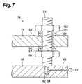
- [Fig. 7] Fig. 7 is a vertical sectional view of an inclination correcting movable point mechanism shown in Fig. 2.
- [Fig. 8] Fig. 8 is a vertical sectional view of a state where a planar member is tilted in the inclination correcting movable point mechanism shown in Fig. 7.
- 1...laser processing apparatus, 4...optical system main part, 11... cooling jacket, 13...laser head, 14... shutter unit, 15... regulator, 22...beam expander, 42...processing objective lens, L...laser light, S... subject.
- In the following, with reference to the drawings, preferred embodiments of the laser processing apparatus in accordance with the present invention will be explained in detail.
- Fig. 1 is a schematic diagram showing an embodiment of the
laser processing apparatus 1 in accordance with the present invention. As shown in Fig. 1, thelaser processing apparatus 1 is an apparatus which irradiates a planar subject S to be observed, which is mounted on astage 2, while positioning a light-converging point P within the subject S, thereby forming a modified region R caused by multiphoton absorption within the subject S. Thestage 2 is adapted to move up and down and left and right and rotate, whereas alaser outputting apparatus 6 mainly constituted by alaser head unit 3, an optical systemmain part 4, and anobjective lens unit 5 is disposed above thestage 2. - The
laser head unit 3 is detachably attached to the upper end portion of the optical systemmain part 4. Thelaser head unit 3 includes an L-shaped cooling jacket 11, whereas acooling pipe 12 through which cooling water circulates is buried in avertical wall 11a of thecooling jacket 11 while in a winding state. Alaser head 13 for emitting laser light L downward and ashutter unit 14 for selectively opening and closing an optical path of the laser light L emitted from thelaser head 13 are detachably attached to the front face of thevertical wall 11a by screws. Therefore, thelaser head 13 can be replaced when damaged. Also, thesame cooling jacket 11 can efficiently cool thelaser head 13, which generates heat when driven, and theshutter unit 14, which generates heat when the optical path of the laser light L is closed, while reducing the size of thelaser processing apparatus 1. Thelaser head 13 uses an Nd:YAG laser, for example, and emits pulsed laser light having a pulse width of 1 µs or less as the laser light L. - A
regulator 15 for adjusting the position and inclination of thecooling jacket 11 is attached to the lower face of abottom wall 11b of thecooling jacket 11 in thelaser head unit 3. Theregulator 15 is used in order for the optical axis α of the laser light L emitted from thelaser head 13 to coincide with an optical axis β set in the optical systemmain part 4 andobjective lens unit 5 so as to extend vertically. Namely, thecooling jacket 11 of thelaser head unit 3 is attached to the optical systemmain part 4 by way of theregulator 15. When theregulator 15 adjusts the position and inclination of thecooling jacket 11 thereafter, the position and inclination of thelaser head 13 is also adjusted in conformity to the movement of thecooling jacket 11. This allows the laser light L to advance into the optical systemmain part 4 with its optical axis α coinciding with the optical axis β. Thebottom wall 11b of thecooling jacket 11 and ahousing 21 of theregulator 15 and optical systemmain part 4 are each formed with a through hole through which the laser light L passes. - A beam expander 22 for enlarging the beam size of the laser light L emitted from the
laser head 13, anoptical attenuator 23 for adjusting the output of the laser light L, an output observationoptical system 24 for observing the output of the laser light L adjusted by theoptical attenuator 23, and a polarization adjustingoptical system 25 for adjusting the polarization of the laser light L are successively arranged on the optical axis β within thehousing 21 of the optical systemmain part 4 from the upper side to lower side. Abeam damper 26 for absorbing the eliminated part of laser light is attached to theoptical attenuator 23, and is connected to thecooling jacket 11 by way of aheat pipe 27. This can prevent thebeam damper 26 having absorbed the laser light from overheating. Thus, the laser light L emitted from thelaser head 13 is adjusted to a predetermined characteristic in the optical systemmain part 4. - For observing the subject S mounted on the
stage 2, alight guide 28 for guiding observation visible light is attached to thehousing 21 of the optical systemmain part 4, whereas aCCD camera 29 is disposed within thehousing 21. The observation visible light is guided by thelight guide 28 into thehousing 21, passes afield stop 31, areticle 32, adichroic mirror 33, etc. in succession, and then is reflected by adichroic mirror 34 disposed on the optical axis β. The reflected observation visible light advances downward on the optical axis β and irradiates the subject S. The laser light L is transmitted through thedichroic mirror 34. - Then, the part of observation visible light reflected by the surface of the subject S advances upward on the optical axis β, so as to be reflected by the
dichroic mirror 34. The light reflected by thedichroic mirror 34 is further reflected by thedichroic mirror 33, and is transmitted through animaging lens 35, etc., so as to be made incident on theCCD camera 29. The image of the subject S captured by theCCD camera 29 is displayed on a monitor (not depicted). Thus, thelight guide 28,CCD camera 29,field stop 31,reticle 32,dichroic mirrors imaging lens 35 constitute the subject observation optical system. - The
objective lens unit 5 is detachably attached to the lower end portion of the optical systemmain part 4. Theobjective lens unit 5 is positioned with respect to the lower end portion of the optical systemmain part 4 by a plurality of positioning pins and thus can easily allow the optical axis β set in the optical systemmain part 4 and the optical axis β set in theobjective lens unit 5 to coincide with each other. A processing objective lens 42 with its optical axis coinciding with the optical axis β is attached to the lower end of ahousing 41 of theobjective lens unit 5 by way of anactuator 43 using a piezoelectric device. Thehousing 21 of the optical systemmain part 4 and thehousing 41 of theobjective lens unit 5 are each formed with a through hole through which the laser light L passes. The peak power density of the laser light L converged by the processing objective lens 42 is at least 1 × 10⁸ (W/cm2) at the light-converging point P. - In order to position the light-converging point P at a predetermined depth from the surface of the subject S, a
laser diode 44 for emitting measurement laser light and a light-receivingpart 45 are disposed within thehousing 41 of theobjective lens unit 5. The measurement laser light is emitted from thelaser diode 44, and then is successively reflected by amirror 46 and ahalf mirror 47, so as to be reflected by adichroic mirror 48 disposed on the optical axis β. The reflected measurement laser light advances downward on the optical axis β, and passes through the processing objective lens 42, so as to irradiate the subject S. The laser light L is transmitted through thedichroic mirror 48. - The part of measurement laser light reflected by the surface of the subject S reenters the processing objective lens 42 and advances upward on the optical axis β, so as to be reflected by the
dichroic mirror 48. The measurement laser light reflected by thedichroic mirror 48 is transmitted through thehalf mirror 47, so as to be made incident on the light-receivingpart 45 and collected on four divided position detecting devices into which a photodiode is equally divided. According to the light image pattern of measurement laser light collected on the four divided position detecting devices, it can be detected where the light-converging point of measurement laser light caused by the processing objective lens 42 is positioned with respect to the surface of the subject S. - Next, with reference to Figs. 2 to 7, the
regulator 15 disposed between the coolingjacket 11 and the optical systemmain part 4 will be explained in more detail. Here, X, Y, and Z axes are assumed to extend along the width, depth, and height of the coolingjacket 11. - As shown in Figs. 2 and 3, the
regulator 15 is constituted by an X-Ydirection correcting mechanism 50 for moving the coolingjacket 11 with respect to the optical systemmain part 4, and aninclination adjusting mechanism 51 for adjusting the inclination of the coolingjacket 11 with respect to the optical systemmain part 4. The X-Ydirection correcting mechanism 50 is constituted by a Y-axis correcting mechanism 52 and anX-axis correcting mechanism 53, whereas theinclination adjusting mechanism 51 is set on the X-Ydirection correcting mechanism 50. - The Y-
axis correcting mechanism 52 comprises aplanar member 54 having a rectangular form, ascrew holder 56 formed at the front-side edge part on atop plate 21a of thehousing 21, afeed screw 57 held along the Y axis by thescrew holder 56, and a pair ofpins top plate 21a. The front side face of theplanar member 54 is formed with ascrew hole 61, whereas the rear-side edge part of theplanar member 54 is formed with a pair ofcutouts - As shown in Figs. 3 and 4, the
planar member 54 is mounted on thetop plate 21a while thepins cutouts feed screw 57 is in mesh with thescrew hole 61. A throughhole 21 b for transmitting therethrough the laser light L emitted from thelaser head 13 is formed at the center of thetop plate 21a, whereas a throughhole 64 for transmitting the laser light L therethrough is similarly formed at the center of theplanar member 54. - The
X-axis correcting mechanism 53 comprises aplanar member 66 having a rectangular form, ascrew holder 67 formed at the left-side edge part on theplanar member 54, afeed screw 68 held along the X axis by thescrew holder 67, and apin 69 erected on theplanar member 54. The left side face of theplanar member 66 is formed with ascrew hole 71, whereas the right-side edge part of theplanar member 66 is formed with acutout 72 extending along the X axis. - As shown in Figs. 3 and 5, the
planar member 66 is mounted on theplanar member 54 while thepin 69 is placed within thecutout 72, whereas thefeed screw 68 is in mesh with thescrew hole 71. A throughhole 73 for passing therethrough the laser light L emitted from thelaser head 13 is formed at the center of theplanar member 66. - As shown in Fig. 3, the
inclination adjusting mechanism 51 is constituted by theplanar member 66, aplanar member 74 having a rectangular form, one inclination correctingfulcrum mechanism 77 and three inclination correctingmovable point mechanisms 78 for connecting theplanar members laser head 13 is formed at the center of theplanar member 74. - As shown in Figs. 3 and 6, the inclination correcting
fulcrum mechanism 77 includes asupport bolt 81, whose leading end of thesupport bolt 81 is formed with a smaller-diameter screw part 82. Thesupport bolt 81 penetrates through ascrew insertion hole 83 of theplanar member 74, whereas the smaller-diameter screw part 82 is in mesh with ascrew hole 84 formed in the upper face of theplanar member 66. Ascrew hole 86 is formed from a side face of theplanar member 66 so as to penetrate through thescrew hole 84. While the smaller-diameter screw part 82 of thesupport bolt 81 is in mesh with thescrew hole 84, afastening bolt 87 meshes with thescrew hole 86, and the leading end of thefastening bolt 87 pushes the smaller-diameter screw part 82, whereby thesupport bolt 81 is firmly secured to theplanar member 66. - Between the
planar members ball 88 through which thesupport bolt 81 penetrates andspherical washers ball 88 is held between the spherical surfaces of the concavespherical washers - On the
planar member 74, a concavespherical washer 92 and a convexspherical washer 93, through which thesupport bolt 81 penetrates, are disposed in mesh with each other, whereas anut 94 is in mesh with thesupport bolt 81 on the upper side of the concavespherical washer 92 and convexspherical washer 93. - As shown in Figs. 3 and 7, each inclination correcting
movable point mechanism 78 includes asupport bolt 81, whereas thesupport bolt 81 penetrates through ascrew insertion hole 83 of theplanar member 74, such that a smaller-diameter screw part 82 is in mesh with ascrew hole 84 formed in the upper face of theplanar member 66. While the smaller-diameter screw part 82 of thesupport bolt 81 is in mesh with thescrew hole 84, afastening bolt 87 meshes with ascrew hole 86 formed at a side face of theplanar member 66, so that the leading end of thefastening bolt 87 pushes the smaller-diameter screw part 82, whereby thesupport bolt 81 is firmly secured to theplanar member 66. - Between the
planar members spherical washer 96 and a convexspherical washer 97, through which thesupport bolt 81 penetrates, are disposed while in mesh with each other. On the lower side of the concavespherical washer 96 and convexspherical washer 97, anut 98 is in mesh with thesupport bolt 81. - On the
planar member 74, a concavespherical washer 99 and a convexspherical washer 101, through which thesupport bolt 81 penetrates, are disposed while in mesh with each other, whereas anut 102 is in mesh with thesupport bolt 81 on the upper side of the concavespherical washer 99 and convexspherical washer 101. - An example of method of using thus configured
regulator 15 will now be explained. Thisregulator 15 is used when replacing thelaser head 13, etc. - When the
feed screw 57 is rotated normally or in reverse, theplanar member 54 moves along the Y axis while being guided by thepins X-axis correcting mechanism 53,inclination adjusting mechanism 51, and coolingjacket 11 located higher than theplanar member 54 move along the Y axis relative to thetop plate 21a, whereby the optical axis α of thelaser head 13 and the optical axis β of the optical systemmain part 4 can coincide with each other along the X axis. - When the
feed screw 68 of theX-axis correcting mechanism 53 is subsequently rotated normally or in reverse, theplanar member 66 moves along the X axis while being guided by thepin 69 as shown in Fig. 5. Along with this movement, theinclination adjusting mechanism 51 and coolingjacket 11 located higher than theplanar member 66 move along the X axis relative to thetop plate 21a, whereby the optical axis α of thelaser head 13 and the optical axis β of the optical systemmain part 4 can coincide with each other along the Y axis. - Further, the
nut 94 in the inclination correctingfulcrum mechanism 77 and the nuts 98, 102 of each inclination correctingmovable point mechanism 78 are loosened in the inclination adjusting mechanism 51 (see Figs. 6 and 7). Then, theplanar member 74 to which the coolingjacket 11 is secured is tilted such that the optical axis α of thelaser head 13 and the optical axis β of the optical systemmain part 4 coincide with each other. Here, in the inclination correctingfulcrum mechanism 77, theplanar member 74 is tilted while the respective concave spherical surfaces of the concavespherical washers ball 88, and the concave spherical surface of the concavespherical washer 92 and the convex spherical surface of the convexspherical washer 93 slide against each other. In each inclination correcting movable point mechanism, as shown in Fig. 8, the convex spherical surface of the convexspherical washer 97 and the concave spherical surface of the concavespherical washer 96 slide against each other, and the concave spherical surface of the concavespherical washer 99 and the convex spherical surface of the convexspherical washer 101 slide against each other. In a state where the inclination of theplanar member 74 is optimized, thenut 94 of theinclination correcting mechanism 77 is fastened downward while the nuts 98, 102 of each inclination correctingmovable point mechanism 78 are fastened toward theplanar member 74 from both sides, whereby theplanar member 74 is secured. - Thus, using the
inclination adjusting mechanism 51 can adjust the inclination of theplanar member 74. Here, the coolingjacket 11 is attached onto theplanar member 74, whereas thelaser head 13 is attached to the coolingjacket 11. Therefore, the inclination of thelaser head 13 can be adjusted when the inclination of theplanar member 74 is adjusted by theinclination adjusting mechanism 51. - When the position and inclination of the
laser head 13 with respect to the optical systemmain part 4 is adjusted by using the X-Ydirection correcting mechanism 50 andinclination adjusting mechanism 51, the optical axis α of thelaser head 13 and the optical axis β of the optical systemmain part 4 can coincide with each other as in the foregoing. Therefore, even when the emitting direction of the laser light L fluctuates among laser heads, theregulator 15 can easily correct the fluctuation in laser light emitting direction among the laser heads 13 each time the laser heads 13 are exchanged. The optical axis adjustment using theregulator 15 can also be carried out when thelaser head 13 is replaced together with the coolingjacket 11. - Though the present invention is specifically explained with reference to the embodiment in the foregoing, the present invention is not limited to the above-mentioned embodiment. For example, motors may be provided so that the
feed screw 57 of the Y-axis correcting mechanism 52 and thefeed screw 68 of theX-axis correcting mechanism 53 are rotated by electric power. While the inclination correctingmovable point mechanisms 96 are provided at three of the four corners connecting theplanar members planar members main part 4 and theobjective lens unit 5 are separated from each other in the above-mentioned embodiment, this is not restrictive, whereby the laser processing apparatus may have a structure in which the optical systemmain part 4 is integrated with theobjective lens unit 5. - The present invention can correct the fluctuation in laser light emitting direction among laser heads.
Claims (3)
- A laser processing apparatus for processing a subject to be processed by irradiating the subject with laser light, the apparatus comprising:a laser head for emitting laser light;a cooling jacket for holding and cooling the laser head;an optical system main part for adjusting the laser light emitted from the laser head to a predetermined characteristic; anda regulator, disposed between the cooling jacket and optical system main part, for adjusting a position and inclination of the cooling jacket with respect to the optical system main part.
- A laser processing apparatus according to claim 1, wherein the cooling jacket holds and cools a shutter unit for opening and closing an optical path of the laser light emitted from the laser head.
- A laser processing apparatus according to claim 1, wherein the optical system main part comprises:a beam expander for adjusting a beam size of the laser light emitted from the laser head;a subject observation optical system for observing the subject; anda processing objective lens for converging the laser light onto and within the subject.
Applications Claiming Priority (2)
| Application Number | Priority Date | Filing Date | Title |
|---|---|---|---|
| JP2003415142A JP3708102B2 (en) | 2003-12-12 | 2003-12-12 | Laser processing equipment |
| PCT/JP2004/018157 WO2005056229A1 (en) | 2003-12-12 | 2004-12-06 | Laser processing device |
Publications (3)
| Publication Number | Publication Date |
|---|---|
| EP1700666A1 true EP1700666A1 (en) | 2006-09-13 |
| EP1700666A4 EP1700666A4 (en) | 2008-12-03 |
| EP1700666B1 EP1700666B1 (en) | 2011-09-14 |
Family
ID=34675121
Family Applications (1)
| Application Number | Title | Priority Date | Filing Date |
|---|---|---|---|
| EP04820181A Expired - Lifetime EP1700666B1 (en) | 2003-12-12 | 2004-12-06 | Laser processing device |
Country Status (9)
| Country | Link |
|---|---|
| US (1) | US7777772B2 (en) |
| EP (1) | EP1700666B1 (en) |
| JP (1) | JP3708102B2 (en) |
| KR (1) | KR101167328B1 (en) |
| CN (1) | CN1890048B (en) |
| AT (1) | ATE524267T1 (en) |
| MY (1) | MY135053A (en) |
| TW (1) | TWI309186B (en) |
| WO (1) | WO2005056229A1 (en) |
Cited By (1)
| Publication number | Priority date | Publication date | Assignee | Title |
|---|---|---|---|---|
| DE102019220263A1 (en) * | 2019-12-19 | 2021-06-24 | MTU Aero Engines AG | Arrangement device which can be removably arranged on a laser welding head for laser deposition welding of an object |
Families Citing this family (13)
| Publication number | Priority date | Publication date | Assignee | Title |
|---|---|---|---|---|
| JP3708102B2 (en) | 2003-12-12 | 2005-10-19 | 浜松ホトニクス株式会社 | Laser processing equipment |
| JP5239151B2 (en) * | 2006-12-07 | 2013-07-17 | コニカミノルタエムジー株式会社 | Inkjet recording device |
| JP5336054B2 (en) | 2007-07-18 | 2013-11-06 | 浜松ホトニクス株式会社 | Processing information supply system provided with processing information supply device |
| KR101051823B1 (en) * | 2009-10-19 | 2011-07-25 | 윤태중 | Laser generator for light guide plate processing |
| CN101804519B (en) * | 2010-03-18 | 2013-05-29 | 张文武 | Laser processing head |
| KR100998484B1 (en) * | 2010-07-07 | 2010-12-06 | 레이져라이팅(주) | Light guide plate laser processing device with constant optical path distance of laser beam |
| KR101425493B1 (en) * | 2012-12-26 | 2014-08-04 | 주식회사 이오테크닉스 | method of laser machining and apparatus adopting the method |
| CN105458501A (en) * | 2015-12-29 | 2016-04-06 | 苏州润昇精密机械有限公司 | Laser welding machine with power-off protection function |
| JP6684472B2 (en) * | 2016-08-09 | 2020-04-22 | ブラザー工業株式会社 | Laser processing equipment |
| KR102134461B1 (en) * | 2018-07-09 | 2020-07-15 | 주식회사기성이엔지 | Laser marking apparatus for hot coil |
| JP7269820B2 (en) * | 2019-08-01 | 2023-05-09 | 能美防災株式会社 | Visual field confirmer |
| GB201913629D0 (en) * | 2019-09-20 | 2019-11-06 | Alltec Angewandte Laserlicht Tech Gmbh | Electromagnetic radiation system |
| CN111975223A (en) * | 2020-08-28 | 2020-11-24 | 东莞市耀霆五金机械有限公司 | 3D numerical control laser cutting machine |
Family Cites Families (21)
| Publication number | Priority date | Publication date | Assignee | Title |
|---|---|---|---|---|
| JPS5729999Y2 (en) * | 1975-03-25 | 1982-06-30 | ||
| JPH02207992A (en) | 1989-02-06 | 1990-08-17 | Mitsubishi Heavy Ind Ltd | Optical head of laser beam machine |
| JP2723320B2 (en) * | 1989-12-19 | 1998-03-09 | 株式会社東芝 | Laser device |
| JPH04244910A (en) * | 1991-01-31 | 1992-09-01 | Nec Corp | Height detection device |
| JP3170023B2 (en) * | 1992-02-27 | 2001-05-28 | ホーヤ株式会社 | Laser processing equipment |
| JPH05261575A (en) | 1992-03-16 | 1993-10-12 | Hitachi Constr Mach Co Ltd | Pulse laser processing machine |
| JP2781718B2 (en) | 1993-10-19 | 1998-07-30 | ミヤチテクノス株式会社 | YAG laser processing machine |
| US5580471A (en) * | 1994-03-30 | 1996-12-03 | Panasonic Technologies, Inc. | Apparatus and method for material treatment and inspection using fiber-coupled laser diode |
| JPH08335732A (en) | 1995-06-08 | 1996-12-17 | Olympus Optical Co Ltd | Laser light source mounting angle adjustment mechanism |
| JP2746254B2 (en) | 1996-04-16 | 1998-05-06 | 住友電気工業株式会社 | Laser processing head |
| JPH1034368A (en) * | 1996-07-18 | 1998-02-10 | Mitsubishi Electric Corp | Laser processing machine |
| JP4273542B2 (en) * | 1998-09-08 | 2009-06-03 | トヨタ自動車株式会社 | Laser welding method |
| US6332276B1 (en) | 2000-03-30 | 2001-12-25 | Ronnie L. Mangel | Articulate laser degree finder |
| US6501772B1 (en) * | 2000-08-11 | 2002-12-31 | Litton Systems, Inc. | Microlaser assembly having a microresonator and aligned electro-optic components |
| JP3983024B2 (en) | 2001-10-12 | 2007-09-26 | 株式会社トプコン | Laser oscillator |
| JP3563384B2 (en) * | 2001-11-08 | 2004-09-08 | 大日本スクリーン製造株式会社 | Image recording device |
| JP2003158315A (en) * | 2001-11-20 | 2003-05-30 | Miyachi Technos Corp | Laser oscillator holding structure |
| JP2003225786A (en) * | 2002-01-30 | 2003-08-12 | Uht Corp | Laser processing unit and processing apparatus provided with the laser processing unit |
| JP3734812B2 (en) * | 2003-11-04 | 2006-01-11 | 浜松ホトニクス株式会社 | Shutter unit and laser processing apparatus using the same |
| JP3708102B2 (en) | 2003-12-12 | 2005-10-19 | 浜松ホトニクス株式会社 | Laser processing equipment |
| JP3708104B2 (en) * | 2004-01-13 | 2005-10-19 | 浜松ホトニクス株式会社 | Laser processing method and laser processing apparatus |
-
2003
- 2003-12-12 JP JP2003415142A patent/JP3708102B2/en not_active Expired - Fee Related
-
2004
- 2004-12-06 EP EP04820181A patent/EP1700666B1/en not_active Expired - Lifetime
- 2004-12-06 KR KR1020067012960A patent/KR101167328B1/en not_active Expired - Fee Related
- 2004-12-06 WO PCT/JP2004/018157 patent/WO2005056229A1/en not_active Ceased
- 2004-12-06 CN CN2004800369097A patent/CN1890048B/en not_active Expired - Fee Related
- 2004-12-06 AT AT04820181T patent/ATE524267T1/en not_active IP Right Cessation
- 2004-12-06 US US10/582,332 patent/US7777772B2/en active Active
- 2004-12-08 TW TW093137879A patent/TWI309186B/en not_active IP Right Cessation
- 2004-12-10 MY MYPI20045118A patent/MY135053A/en unknown
Cited By (1)
| Publication number | Priority date | Publication date | Assignee | Title |
|---|---|---|---|---|
| DE102019220263A1 (en) * | 2019-12-19 | 2021-06-24 | MTU Aero Engines AG | Arrangement device which can be removably arranged on a laser welding head for laser deposition welding of an object |
Also Published As
| Publication number | Publication date |
|---|---|
| CN1890048B (en) | 2010-10-13 |
| TWI309186B (en) | 2009-05-01 |
| EP1700666B1 (en) | 2011-09-14 |
| KR101167328B1 (en) | 2012-07-19 |
| ATE524267T1 (en) | 2011-09-15 |
| JP3708102B2 (en) | 2005-10-19 |
| JP2005169476A (en) | 2005-06-30 |
| WO2005056229A1 (en) | 2005-06-23 |
| MY135053A (en) | 2008-01-31 |
| KR20060108733A (en) | 2006-10-18 |
| CN1890048A (en) | 2007-01-03 |
| US7777772B2 (en) | 2010-08-17 |
| US20080019405A1 (en) | 2008-01-24 |
| EP1700666A4 (en) | 2008-12-03 |
| TW200531772A (en) | 2005-10-01 |
Similar Documents
| Publication | Publication Date | Title |
|---|---|---|
| US7777772B2 (en) | Laser processing device | |
| US7570407B2 (en) | Scanning mechanism, method of machining workpiece, and machine tool | |
| JP7771286B2 (en) | Laser processing device and laser processing system | |
| JP6885071B2 (en) | Laser machining machine and laser machining method | |
| US7595895B2 (en) | Laser beam machining system | |
| JP5707092B2 (en) | Laser processing equipment | |
| US7626746B2 (en) | Shutter unit and laser processing device using same | |
| US5991015A (en) | Beam monitoring assembly | |
| JP5465495B2 (en) | Laser processing equipment | |
| KR102685373B1 (en) | laser processing device | |
| TWI890771B (en) | Laser processing equipment | |
| KR101394398B1 (en) | Regulator of camera module and setting method of the same | |
| TWI834747B (en) | Laser processing equipment | |
| JP7219590B2 (en) | Laser processing equipment | |
| KR20230057528A (en) | Terahertz wave reflective optics module | |
| Boyd et al. | Alignment and diagnostics of the National Ignition Facility laser system | |
| CN212704966U (en) | Superhard materials processing equipment | |
| KR102968319B1 (en) | Optical pointing device for adjusting direction of camera | |
| KR102850557B1 (en) | Laser processing apparatus | |
| US20250205813A1 (en) | Laser machining process using a scanner optical system | |
| KR20060011163A (en) | Inspection device using optical module | |
| KR102776517B1 (en) | Laser processing device | |
| KR20010081618A (en) | Laser machining apparatus with real time observation function of work surface | |
| JP2002001554A (en) | Laser processing apparatus and teaching torch |
Legal Events
| Date | Code | Title | Description |
|---|---|---|---|
| PUAI | Public reference made under article 153(3) epc to a published international application that has entered the european phase |
Free format text: ORIGINAL CODE: 0009012 |
|
| 17P | Request for examination filed |
Effective date: 20060616 |
|
| AK | Designated contracting states |
Kind code of ref document: A1 Designated state(s): AT BE BG CH CY CZ DE DK EE ES FI FR GB GR HU IE IS IT LI LT LU MC NL PL PT RO SE SI SK TR |
|
| DAX | Request for extension of the european patent (deleted) | ||
| A4 | Supplementary search report drawn up and despatched |
Effective date: 20081031 |
|
| RIC1 | Information provided on ipc code assigned before grant |
Ipc: H01S 3/04 20060101ALI20081027BHEP Ipc: B23K 26/06 20060101AFI20050629BHEP |
|
| 17Q | First examination report despatched |
Effective date: 20090526 |
|
| GRAP | Despatch of communication of intention to grant a patent |
Free format text: ORIGINAL CODE: EPIDOSNIGR1 |
|
| GRAS | Grant fee paid |
Free format text: ORIGINAL CODE: EPIDOSNIGR3 |
|
| GRAA | (expected) grant |
Free format text: ORIGINAL CODE: 0009210 |
|
| AK | Designated contracting states |
Kind code of ref document: B1 Designated state(s): AT BE BG CH CY CZ DE DK EE ES FI FR GB GR HU IE IS IT LI LT LU MC NL PL PT RO SE SI SK TR |
|
| REG | Reference to a national code |
Ref country code: GB Ref legal event code: FG4D |
|
| REG | Reference to a national code |
Ref country code: CH Ref legal event code: NV Representative=s name: ISLER & PEDRAZZINI AG Ref country code: CH Ref legal event code: EP |
|
| REG | Reference to a national code |
Ref country code: IE Ref legal event code: FG4D |
|
| REG | Reference to a national code |
Ref country code: DE Ref legal event code: R096 Ref document number: 602004034386 Country of ref document: DE Effective date: 20111117 |
|
| REG | Reference to a national code |
Ref country code: NL Ref legal event code: T3 |
|
| PG25 | Lapsed in a contracting state [announced via postgrant information from national office to epo] |
Ref country code: SE Free format text: LAPSE BECAUSE OF FAILURE TO SUBMIT A TRANSLATION OF THE DESCRIPTION OR TO PAY THE FEE WITHIN THE PRESCRIBED TIME-LIMIT Effective date: 20110914 Ref country code: LT Free format text: LAPSE BECAUSE OF FAILURE TO SUBMIT A TRANSLATION OF THE DESCRIPTION OR TO PAY THE FEE WITHIN THE PRESCRIBED TIME-LIMIT Effective date: 20110914 Ref country code: FI Free format text: LAPSE BECAUSE OF FAILURE TO SUBMIT A TRANSLATION OF THE DESCRIPTION OR TO PAY THE FEE WITHIN THE PRESCRIBED TIME-LIMIT Effective date: 20110914 |
|
| LTIE | Lt: invalidation of european patent or patent extension |
Effective date: 20110914 |
|
| PG25 | Lapsed in a contracting state [announced via postgrant information from national office to epo] |
Ref country code: CY Free format text: LAPSE BECAUSE OF FAILURE TO SUBMIT A TRANSLATION OF THE DESCRIPTION OR TO PAY THE FEE WITHIN THE PRESCRIBED TIME-LIMIT Effective date: 20110914 Ref country code: GR Free format text: LAPSE BECAUSE OF FAILURE TO SUBMIT A TRANSLATION OF THE DESCRIPTION OR TO PAY THE FEE WITHIN THE PRESCRIBED TIME-LIMIT Effective date: 20111215 Ref country code: AT Free format text: LAPSE BECAUSE OF FAILURE TO SUBMIT A TRANSLATION OF THE DESCRIPTION OR TO PAY THE FEE WITHIN THE PRESCRIBED TIME-LIMIT Effective date: 20110914 Ref country code: SI Free format text: LAPSE BECAUSE OF FAILURE TO SUBMIT A TRANSLATION OF THE DESCRIPTION OR TO PAY THE FEE WITHIN THE PRESCRIBED TIME-LIMIT Effective date: 20110914 |
|
| REG | Reference to a national code |
Ref country code: AT Ref legal event code: MK05 Ref document number: 524267 Country of ref document: AT Kind code of ref document: T Effective date: 20110914 |
|
| PG25 | Lapsed in a contracting state [announced via postgrant information from national office to epo] |
Ref country code: BE Free format text: LAPSE BECAUSE OF FAILURE TO SUBMIT A TRANSLATION OF THE DESCRIPTION OR TO PAY THE FEE WITHIN THE PRESCRIBED TIME-LIMIT Effective date: 20110914 |
|
| PG25 | Lapsed in a contracting state [announced via postgrant information from national office to epo] |
Ref country code: IS Free format text: LAPSE BECAUSE OF FAILURE TO SUBMIT A TRANSLATION OF THE DESCRIPTION OR TO PAY THE FEE WITHIN THE PRESCRIBED TIME-LIMIT Effective date: 20120114 Ref country code: SK Free format text: LAPSE BECAUSE OF FAILURE TO SUBMIT A TRANSLATION OF THE DESCRIPTION OR TO PAY THE FEE WITHIN THE PRESCRIBED TIME-LIMIT Effective date: 20110914 Ref country code: CZ Free format text: LAPSE BECAUSE OF FAILURE TO SUBMIT A TRANSLATION OF THE DESCRIPTION OR TO PAY THE FEE WITHIN THE PRESCRIBED TIME-LIMIT Effective date: 20110914 |
|
| PG25 | Lapsed in a contracting state [announced via postgrant information from national office to epo] |
Ref country code: RO Free format text: LAPSE BECAUSE OF FAILURE TO SUBMIT A TRANSLATION OF THE DESCRIPTION OR TO PAY THE FEE WITHIN THE PRESCRIBED TIME-LIMIT Effective date: 20110914 Ref country code: PL Free format text: LAPSE BECAUSE OF FAILURE TO SUBMIT A TRANSLATION OF THE DESCRIPTION OR TO PAY THE FEE WITHIN THE PRESCRIBED TIME-LIMIT Effective date: 20110914 Ref country code: EE Free format text: LAPSE BECAUSE OF FAILURE TO SUBMIT A TRANSLATION OF THE DESCRIPTION OR TO PAY THE FEE WITHIN THE PRESCRIBED TIME-LIMIT Effective date: 20110914 Ref country code: PT Free format text: LAPSE BECAUSE OF FAILURE TO SUBMIT A TRANSLATION OF THE DESCRIPTION OR TO PAY THE FEE WITHIN THE PRESCRIBED TIME-LIMIT Effective date: 20120116 Ref country code: IT Free format text: LAPSE BECAUSE OF FAILURE TO SUBMIT A TRANSLATION OF THE DESCRIPTION OR TO PAY THE FEE WITHIN THE PRESCRIBED TIME-LIMIT Effective date: 20110914 |
|
| PLBE | No opposition filed within time limit |
Free format text: ORIGINAL CODE: 0009261 |
|
| STAA | Information on the status of an ep patent application or granted ep patent |
Free format text: STATUS: NO OPPOSITION FILED WITHIN TIME LIMIT |
|
| PG25 | Lapsed in a contracting state [announced via postgrant information from national office to epo] |
Ref country code: DK Free format text: LAPSE BECAUSE OF FAILURE TO SUBMIT A TRANSLATION OF THE DESCRIPTION OR TO PAY THE FEE WITHIN THE PRESCRIBED TIME-LIMIT Effective date: 20110914 Ref country code: MC Free format text: LAPSE BECAUSE OF NON-PAYMENT OF DUE FEES Effective date: 20111231 |
|
| 26N | No opposition filed |
Effective date: 20120615 |
|
| REG | Reference to a national code |
Ref country code: IE Ref legal event code: MM4A |
|
| REG | Reference to a national code |
Ref country code: DE Ref legal event code: R097 Ref document number: 602004034386 Country of ref document: DE Effective date: 20120615 |
|
| PG25 | Lapsed in a contracting state [announced via postgrant information from national office to epo] |
Ref country code: IE Free format text: LAPSE BECAUSE OF NON-PAYMENT OF DUE FEES Effective date: 20111206 |
|
| PG25 | Lapsed in a contracting state [announced via postgrant information from national office to epo] |
Ref country code: ES Free format text: LAPSE BECAUSE OF FAILURE TO SUBMIT A TRANSLATION OF THE DESCRIPTION OR TO PAY THE FEE WITHIN THE PRESCRIBED TIME-LIMIT Effective date: 20111225 |
|
| PG25 | Lapsed in a contracting state [announced via postgrant information from national office to epo] |
Ref country code: LU Free format text: LAPSE BECAUSE OF NON-PAYMENT OF DUE FEES Effective date: 20111206 |
|
| PG25 | Lapsed in a contracting state [announced via postgrant information from national office to epo] |
Ref country code: BG Free format text: LAPSE BECAUSE OF FAILURE TO SUBMIT A TRANSLATION OF THE DESCRIPTION OR TO PAY THE FEE WITHIN THE PRESCRIBED TIME-LIMIT Effective date: 20111214 |
|
| PG25 | Lapsed in a contracting state [announced via postgrant information from national office to epo] |
Ref country code: TR Free format text: LAPSE BECAUSE OF FAILURE TO SUBMIT A TRANSLATION OF THE DESCRIPTION OR TO PAY THE FEE WITHIN THE PRESCRIBED TIME-LIMIT Effective date: 20110914 |
|
| PG25 | Lapsed in a contracting state [announced via postgrant information from national office to epo] |
Ref country code: HU Free format text: LAPSE BECAUSE OF FAILURE TO SUBMIT A TRANSLATION OF THE DESCRIPTION OR TO PAY THE FEE WITHIN THE PRESCRIBED TIME-LIMIT Effective date: 20110914 |
|
| PGFP | Annual fee paid to national office [announced via postgrant information from national office to epo] |
Ref country code: CH Payment date: 20141212 Year of fee payment: 11 Ref country code: GB Payment date: 20141203 Year of fee payment: 11 |
|
| PGFP | Annual fee paid to national office [announced via postgrant information from national office to epo] |
Ref country code: FR Payment date: 20141208 Year of fee payment: 11 Ref country code: NL Payment date: 20141108 Year of fee payment: 11 |
|
| REG | Reference to a national code |
Ref country code: CH Ref legal event code: PL |
|
| GBPC | Gb: european patent ceased through non-payment of renewal fee |
Effective date: 20151206 |
|
| REG | Reference to a national code |
Ref country code: NL Ref legal event code: MM Effective date: 20160101 |
|
| REG | Reference to a national code |
Ref country code: FR Ref legal event code: ST Effective date: 20160831 |
|
| PG25 | Lapsed in a contracting state [announced via postgrant information from national office to epo] |
Ref country code: GB Free format text: LAPSE BECAUSE OF NON-PAYMENT OF DUE FEES Effective date: 20151206 Ref country code: CH Free format text: LAPSE BECAUSE OF NON-PAYMENT OF DUE FEES Effective date: 20151231 Ref country code: LI Free format text: LAPSE BECAUSE OF NON-PAYMENT OF DUE FEES Effective date: 20151231 Ref country code: NL Free format text: LAPSE BECAUSE OF NON-PAYMENT OF DUE FEES Effective date: 20160101 |
|
| PG25 | Lapsed in a contracting state [announced via postgrant information from national office to epo] |
Ref country code: FR Free format text: LAPSE BECAUSE OF NON-PAYMENT OF DUE FEES Effective date: 20151231 |
|
| PGFP | Annual fee paid to national office [announced via postgrant information from national office to epo] |
Ref country code: DE Payment date: 20220622 Year of fee payment: 19 |
|
| P01 | Opt-out of the competence of the unified patent court (upc) registered |
Effective date: 20230509 |
|
| REG | Reference to a national code |
Ref country code: DE Ref legal event code: R119 Ref document number: 602004034386 Country of ref document: DE |
|
| PG25 | Lapsed in a contracting state [announced via postgrant information from national office to epo] |
Ref country code: DE Free format text: LAPSE BECAUSE OF NON-PAYMENT OF DUE FEES Effective date: 20240702 |
|
| PG25 | Lapsed in a contracting state [announced via postgrant information from national office to epo] |
Ref country code: DE Free format text: LAPSE BECAUSE OF NON-PAYMENT OF DUE FEES Effective date: 20240702 |