EP1700506B1 - Dynamic antenna control - Google Patents
Dynamic antenna control Download PDFInfo
- Publication number
- EP1700506B1 EP1700506B1 EP03819183A EP03819183A EP1700506B1 EP 1700506 B1 EP1700506 B1 EP 1700506B1 EP 03819183 A EP03819183 A EP 03819183A EP 03819183 A EP03819183 A EP 03819183A EP 1700506 B1 EP1700506 B1 EP 1700506B1
- Authority
- EP
- European Patent Office
- Prior art keywords
- interfering signal
- antenna elements
- overlap
- beam patterns
- signal
- Prior art date
- Legal status (The legal status is an assumption and is not a legal conclusion. Google has not performed a legal analysis and makes no representation as to the accuracy of the status listed.)
- Expired - Lifetime
Links
Images


Classifications
-
- H—ELECTRICITY
- H04—ELECTRIC COMMUNICATION TECHNIQUE
- H04W—WIRELESS COMMUNICATION NETWORKS
- H04W16/00—Network planning, e.g. coverage or traffic planning tools; Network deployment, e.g. resource partitioning or cells structures
- H04W16/24—Cell structures
- H04W16/28—Cell structures using beam steering
-
- H—ELECTRICITY
- H04—ELECTRIC COMMUNICATION TECHNIQUE
- H04W—WIRELESS COMMUNICATION NETWORKS
- H04W16/00—Network planning, e.g. coverage or traffic planning tools; Network deployment, e.g. resource partitioning or cells structures
- H04W16/14—Spectrum sharing arrangements between different networks
-
- H—ELECTRICITY
- H04—ELECTRIC COMMUNICATION TECHNIQUE
- H04W—WIRELESS COMMUNICATION NETWORKS
- H04W16/00—Network planning, e.g. coverage or traffic planning tools; Network deployment, e.g. resource partitioning or cells structures
- H04W16/24—Cell structures
Definitions
- the present invention relates generally to wireless radio communications systems, such as cellular communication systems, having mobile stations and a radio network infrastructure. More particularly, the present invention facilitates a method and system for reducing undesired interference caused by signal sources in a cellular radio communication network such as Code Division Multiple Access (CDMA) networks, Global System for Mobile (GSM) communication systems, Personal Handyphone System (PHS) and Pacific Digital Cellular (PDC).
- CDMA Code Division Multiple Access
- GSM Global System for Mobile
- PHS Personal Handyphone System
- PDC Pacific Digital Cellular
- wireless communication systems such as 2.5 and 3.rd generation networks, based on standards such as United States Digital Cellular (USDC IS-54, IS-94 and ID-136), Global System for Mobile communication (GSM), Code Division Multiple Access (CDMA, IS-95) deploy a cellular concept of network coverage for mobile stations (MS) by means of a plurality of fixed Radio Base Stations (RBS) provided with antenna's.
- USDC IS-54, IS-94 and ID-136 Global System for Mobile communication
- GSM Global System for Mobile communication
- CDMA Code Division Multiple Access
- MS mobile stations
- RBS Radio Base Stations
- a base station provides its transmitting signal and retrieves its receiving signal from an antenna, mounted at an antenna mast.
- Antenna masts are usually placed at locations such that the one or more antennas, mounted in said mast, provide a predefined coverage of the radio cell, serviced by an RBS.
- Undesired signals may be generated by interfering signal sources as e.g. other (unsynchronised) radio systems operating in the same bandwidth, or not properly suppressed equipment within the service area of the cell, having a transmit level that causes interference with the desired signals.
- One of the solutions to this interference problem is to change the tilt of the antenna.
- the antenna For interfering signal sources close to the antenna, the antenna is tilted upward to reduce the nearby sensitivity. Likewise the antenna is tilted downward when the interfering signal source is in the outer part of the coverage area of the base station.
- Tilting of an antenna of an RBS as state of the art method to suppress Interference has a disadvantage in that a decrease of sensitivity for interfering signal sources also affects sensitivity of the RBS's for reception of the signals from MS's.
- RBS's are provided with a single mast with 3 antenna elements where each antenna element covers a sector of approximately 120 degrees, having some overlap between the beams of the adjacent antenna elements.
- Tilting of antenna elements affects reception of mobile stations which limits the tilting in practice. This undesired limiting effect is even more extensive when the interfering signal source is present at the overlapping area of the radiation pattern of two antenna elements of the same mast, requiring both antenna elements to be tilted.
- WO 01/1547 discloses a system and method for dynamically sizing sectors of a multi-sectored antenna radiation pattern of a cell of a collar wireless communication system, by appropriate azimuthal and longitudinal adaptation of the antenna radiation patterns dependent on forward and reverse traffic loads across the sectors, thus increasing the number of channels, or other resources available to a particular area within the cell, or forcing a hand off of a communication device causing interference.
- the method according to the present invention is based on the insight that interference, caused by an interfering signal source within the coverage area of a cell, could be reduced by positioning the overlap of coverage of two antenna elements in the direction of the interfering signal source.
- the superimposing effect of radio waves of the two antenna elements causes a reduction of interference when the interfering signal source is physically positioned at a dip of the sensitivity pattern for a desired frequency.
- Altering the overlap area of antenna element beam areas in the horizontal plane could be achieved by changing the bearing of one or more antenna elements, depending on the level of interference, the sensitivity pattern for each antenna element, the coverage area of the antenna elements, the position of the interfering signal source and position of the antenna elements with regard to the overlap area between adjacent antenna elements.
- Applying the method and system according to the present invention reduces the sensitivity for desired frequencies in the horizontal plane in the bearing of the position of the interfering signal source.
- this area is considerable small compared to the total coverage area of each antenna element, the reduction of sensitivity only affects this small part of the total coverage area of the antenna elements, thereby reducing the effect of the interfering signal source on desired signals at the remaining part of the coverage area.
- the present invention could be combined with the prior art tilting solution as to achieve an even more reduction of undesired signals from interfering signal sources.
- bearing of antenna elements should be altered as to achieve the effect of reduction of an interfering signal source.
- the alteration could be achieved mechanically, as will be explained in the present invention, however the method could be deployed as well in an electronic way.
- the method and system of the invention may be deployed within a state of the art implementation of public cellular networks such as CDMA, GSM and PDC as well in many microcellular/indoor networks such as Digital European Cordless Telephone (DECT), Personal Access Communication Systems (PACS), Personal Handyphone System (PHS), as well as for systems operating in unlicensed radio spectrum bands such as Industrial, Scientific and Medical (ISM) bands.
- public cellular networks such as CDMA, GSM and PDC
- microcellular/indoor networks such as Digital European Cordless Telephone (DECT), Personal Access Communication Systems (PACS), Personal Handyphone System (PHS), as well as for systems operating in unlicensed radio spectrum bands such as Industrial, Scientific and Medical (ISM) bands.
- DECT Digital European Cordless Telephone
- PPS Personal Access Communication Systems
- PHS Personal Handyphone System
- ISM Industrial, Scientific and Medical
- the present invention provides the advantage that the impact of an interference source is in a wireless radio communication system is reduced to only a limited area of coverage of antenna elements, thereby improving radio communication.
- a mast with two or more antenna elements could be adjusted such that the overlapping area of coverage of two antenna elements is directed in the bearing of the interfering signal source.
- one or more adjacent antenna elements could be adjusted such that overlapping area of coverage is altered.
- the received signal of one of the antenna elements is delayed according to prior art method as to change the superimposing wave pattern at the overlapping area of coverage.
- the invention is presented against the background and within the scope of state of the art wireless cellular communication systems.
- the present invention may be employed in any wireless communication system where sectorised antenna systems are deployed.
- Fig. 1a illustrates schematically a top view of a coverage area of a sectorised antenna comprising 3 antenna elements of an RBS within a cellular communication system.
- the beam patterns of the adjacent antenna elements show an overlap.
- a prior art method of reducing interference by interfering signal sources comprises tilting upward or downward of an antenna element. By tilting an antenna element, as to reduce the interference of an interfering signal source positioned within the beam pattern of the antenna element, the coverage area is deviated from the desired coverage area of said antenna beam pattern where radio communication between RBS's and MS's could be deployed. By tilting one antenna element all MS's within the range of angle, denoted in the figure as "A", practically at least 90 degrees, are affected by this tilting action.
- the present invention does not require tilting, with its negative effects on the desired coverage by the beam patterns, but provides a solution where the mast with its mounted antenna elements is positioned such that an interfering signal source is positioned into the overlap of the beam patterns of adjacent antenna elements by rotating the mast with the antenna elements.
- Fig. 1b depicts schematically a top view of a coverage area of a sectorised antenna comprising 3 antenna elements of an RBS within a cellular communication system where the total beam pattern is rotated.
- an anti-clockwise rotation is depicted, although a clockwise rotation could be achieved as well.
- the beam pattern is rotated in small steps in such a way as to have to interfering signal source positioned within an overlap area of two adjacent beam patterns of two adjacent antenna elements.
- the rotating action is deployed until the reception of the signal, at both adjacent antenna elements, of the interfering signal source is reduced to a minimum level.
- this action will be finalised when the signal reception is substantially equal at both antenna elements and reduced to a minimum level.
- this action be continues until the a minimum level remains constant, or the interfering signal reaches a level below a threshold value that has to be chosen a practical value in relation to the value of desired signals.
- Fig. 1c depicts schematically a top view of a coverage area of a sectorised antenna comprising three antenna elements of an RBS within a cellular communication system where the one beam pattern of an antenna element is altered as to alter the overlap area with a beam pattern of an adjacent antenna element.
- the action of altering only one antenna element is different from rotating all antenna elements as depicted at fig. 1b , the effects of altering the overlap of the beam pattern with regard to an interfering signal from an interfering signal source are the same.
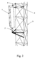
- Fig. 2 presents schematically an antenna element at a mast according to the invention as a mechanical solution. Although only one element is depicted for clarity, it should be understood that there should be at least two antenna elements. Practical constructions according to the invention have three to four antenna elements mounted at the same mast, preferably, but not required, at the same height.
- Antenna element 1 is connectable mounted by means of two actuators 4 and rotating joint 2, enabling the antenna element pivoting.
- Actuators 4 and rotating joint are connectable mounted to mast 3.
- Actuators 4 and rotating joint 2 are dimensioned to allow the antenna element 1 to have a rotating angle in the horizontal plane substantially at 90 degrees to both sides from its centre position. Actuators 4 are remote controlled. Actuators 4 also enable upward- and downward-tilting of the antenna element 1 by remote control.
- Actuators 4 and rotating joint 2 provide means to independently change bearing and tilt of the antenna element 1. For tilting the same steering signal is provided to both actuators 4, and for bearing one actuator 4 is provided with the inverse steering signal from the other actuator 4.
- Fig. 3 presents schematically an interference control system according to the present invention.
- Antenna element 1 is connectable mounted via actuators 4 to mast 3 (not shown) where the actuators 4 are remote controlled by tilt/bearing control 6.
- Antenna elements 1 are deployed for sending as well as receiving signals from and to an RBS.
- a signal received by antenna element 1 is forwarded to controllable phase shift device 5, providing a controlled amount of phase shift to the signal, from where the signal is forwarded to both the receiving side of the RBS, denoted as RBS Tx, and to Interference control 7.
- Interference control 7 receives interference characteristics information from a Radio base station controller (RBC) and the received signals by antenna elements 1 via controllable phase shift device 5.
- RBS Tx Radio base station controller
- Interference control 7 controls the phase shift devices 5 and the tilting and bearing of antenna elements 1 via the tilt/bearing control 6.
- the sending side of the RBS is connected to the antenna elements 1, denoted as RBS Tx.
- the concept of the present invention consist of adapting the overlap of the beam patterns of two adjacent antenna elements 1, such that an interfering signal, of an interfering source positioned within the overlap, yields a minimum signal value at the two adjacent antenna elements 1.
- Interference control 7 applies methods, stated below, until the signal strength of the interfering signal source is below a desired threshold or has a minimum value above said threshold.
- a RBC forwards interference characteristics and a predefined value for the threshold to interference control 7.
- the impact of the interfering signal source is reduced by rotating all antenna elements 1.
- Interference control 7 checks the received signal strength from each antenna element 1 to obtain the strongest and the 2nd strongest signal providing antenna element 1. All antenna elements 1 are then rotated in bearing in the direction, as shown in fig. 1b from the second strongest to the strongest antenna element 1 until the received signal strength of the interference of these two antenna elements 1 is substantial equal. The interference control 7 will continue to rotate, based on the measured values from each antenna element 1.
- the interference source could be moving, giving a constant bearing change.
- the antenna elements 1 are however limited to a bearing change of somewhat more then 180 degrees. If movement is detected beyond a maximum of 60 degrees (for 3 element, if 4 are used 45 degrees etc.) from the centre position of an element, the controller rotates all antenna elements 1 by 120 degrees (if 3 elements are used, or 90 degrees if 4 elements are used, etc.) in opposite direction to obtain a new starting point.
- the impact of the interfering signal source is reduced by rotating one antenna element 1.
- Interference control 7 checks the received signal strength as at the first embodiment to obtain the strongest and 2nd strongest receiving element. The interference controller 7 then rotates the strongest receiving antenna element 1 in bearing away from the 2nd strongest receiving antenna element 1, as shown in fig. 1c . In case the average interference signal strength increases the movement of the strongest receiving element is changed in the direction towards the 2nd strongest receiving antenna element 1. The interference control 7 will continue to adapt the rotation of the one antenna element 1 based on the measured signal strength of each antenna element 1. It might be clear that the bearing change of a single antenna element 1 is superimposed on the rotation of all antenna elements 1 in the first embodiment.
- the impact of the interfering signal 1 source is reduced by changing phase shift of signals received from two antenna elements 1.
- the interface control 7 determines a strongest and second strongest receiving antenna element 1.
- a positive phase shift by means of controllable phase shift device 5 is applied to the received signal from of the second strongest antenna element 1 and an equal negative phase shift is applied by means of controllable phase shift device 5 to the received signal from the strongest receiving antenna element 1.
- the phase shift is decreased or increased opposite to the increase or decrease of the average interference signal strength of the two antenna elements 1.
- the impact of the interfering signal source is reduced by dynamically tilting one or more antenna elements 1.
- first and second strongest receiving antenna elements 1 are determined.
- the tilting of these two antenna elements 1 is changed dynamically.
- Reduction of sensitivity for interfering signal sources according to the present invention in a number of embodiments and named combinations thereof provide an advantageous method for radio communication in wireless networks.
- Rotating of the all beam pattern of antenna elements 1 as suggested at the description of the first embodiment could also be deployed, however less advantageously by rotating the physical mast with mounted antenna elements 1.
- the present invention could be deployed with any type of sectorised antenna element 1.
- first, second and fourth embodiments are presented as a mechanical solution with actuators 4, it should be understood that the method as disclosed could also be applied where bearing and tilting of the beam pattern of antenna elements 1 is achieved as an electronic equivalent.
Landscapes
- Engineering & Computer Science (AREA)
- Computer Networks & Wireless Communication (AREA)
- Signal Processing (AREA)
- Mobile Radio Communication Systems (AREA)
- Variable-Direction Aerials And Aerial Arrays (AREA)
- Details Of Aerials (AREA)
Abstract
Description
- The present invention relates generally to wireless radio communications systems, such as cellular communication systems, having mobile stations and a radio network infrastructure. More particularly, the present invention facilitates a method and system for reducing undesired interference caused by signal sources in a cellular radio communication network such as Code Division Multiple Access (CDMA) networks, Global System for Mobile (GSM) communication systems, Personal Handyphone System (PHS) and Pacific Digital Cellular (PDC).
- State of the art wireless communication systems, such as 2.5 and 3.rd generation networks, based on standards such as United States Digital Cellular (USDC IS-54, IS-94 and ID-136), Global System for Mobile communication (GSM), Code Division Multiple Access (CDMA, IS-95) deploy a cellular concept of network coverage for mobile stations (MS) by means of a plurality of fixed Radio Base Stations (RBS) provided with antenna's.
- In most cases a base station provides its transmitting signal and retrieves its receiving signal from an antenna, mounted at an antenna mast. Antenna masts are usually placed at locations such that the one or more antennas, mounted in said mast, provide a predefined coverage of the radio cell, serviced by an RBS.
- It will be understood that communication over the air interface within a cell, just like any radio propagation, might be subject to unexpected and undesired signals, interfering with the desired signals between RBS and MS.
- Undesired signals may be generated by interfering signal sources as e.g. other (unsynchronised) radio systems operating in the same bandwidth, or not properly suppressed equipment within the service area of the cell, having a transmit level that causes interference with the desired signals.
- One of the solutions to this interference problem is to change the tilt of the antenna. For interfering signal sources close to the antenna, the antenna is tilted upward to reduce the nearby sensitivity. Likewise the antenna is tilted downward when the interfering signal source is in the outer part of the coverage area of the base station. Tilting of an antenna of an RBS as state of the art method to suppress Interference has a disadvantage in that a decrease of sensitivity for interfering signal sources also affects sensitivity of the RBS's for reception of the signals from MS's.
- Most commonly deployed RBS's are provided with a single mast with 3 antenna elements where each antenna element covers a sector of approximately 120 degrees, having some overlap between the beams of the adjacent antenna elements.
- Even when encountering the fact that there is some overlap, tilting of an antenna element will have impact on a part of an antenna element beam pattern of at least 90 degrees resulting in a deviation of the desired coverage area of said antenna beam pattern where radio communication between RBS's and MS's could be reduced.
- Tilting of antenna elements affects reception of mobile stations which limits the tilting in practice. This undesired limiting effect is even more extensive when the interfering signal source is present at the overlapping area of the radiation pattern of two antenna elements of the same mast, requiring both antenna elements to be tilted.
-
WO 01/1547 - It is an object of the present invention to improve radio communication in a wireless radio communication system by providing a method of reducing the impact of an interfering signal source in respect of a desired radio signal.
- It is a further object of the present invention to provide a interference control system for operation in a wireless radio communication system, and a Radio Base Station for operation in a cellular communication network, in accordance with the improved method of the invention.
- These and other advantages are achieved by the present invention in a method for reducing undesired interference from a radio signal source in a wireless radio communication system, as set forth in
claim 1, an interference control system for use within a wireless radio communication system, as set forth in claim 13, and a Radio Base Station for use in a cellular communication network, as set forth in claim 16. Other embodiments of the invention are claimed in the further claims. - The method according to the present invention is based on the insight that interference, caused by an interfering signal source within the coverage area of a cell, could be reduced by positioning the overlap of coverage of two antenna elements in the direction of the interfering signal source. In relation to the position of the interfering signal source, the superimposing effect of radio waves of the two antenna elements causes a reduction of interference when the interfering signal source is physically positioned at a dip of the sensitivity pattern for a desired frequency.
- Altering the overlap area of antenna element beam areas in the horizontal plane could be achieved by changing the bearing of one or more antenna elements, depending on the level of interference, the sensitivity pattern for each antenna element, the coverage area of the antenna elements, the position of the interfering signal source and position of the antenna elements with regard to the overlap area between adjacent antenna elements.
- Applying the method and system according to the present invention reduces the sensitivity for desired frequencies in the horizontal plane in the bearing of the position of the interfering signal source. However as this area is considerable small compared to the total coverage area of each antenna element, the reduction of sensitivity only affects this small part of the total coverage area of the antenna elements, thereby reducing the effect of the interfering signal source on desired signals at the remaining part of the coverage area.
- The present invention could be combined with the prior art tilting solution as to achieve an even more reduction of undesired signals from interfering signal sources.
- The present invention could as well be combined with the prior art solution as delaying a signal from one of the antenna elements as to achieve an even more reduction of undesired signals from interfering signal sources
- As is indicated the bearing of antenna elements should be altered as to achieve the effect of reduction of an interfering signal source. The alteration could be achieved mechanically, as will be explained in the present invention, however the method could be deployed as well in an electronic way.
- The method and system of the invention may be deployed within a state of the art implementation of public cellular networks such as CDMA, GSM and PDC as well in many microcellular/indoor networks such as Digital European Cordless Telephone (DECT), Personal Access Communication Systems (PACS), Personal Handyphone System (PHS), as well as for systems operating in unlicensed radio spectrum bands such as Industrial, Scientific and Medical (ISM) bands.
- The present invention provides the advantage that the impact of an interference source is in a wireless radio communication system is reduced to only a limited area of coverage of antenna elements, thereby improving radio communication.
- In a first embodiment, a mast with two or more antenna elements could be adjusted such that the overlapping area of coverage of two antenna elements is directed in the bearing of the interfering signal source.
- In a second embodiment, one or more adjacent antenna elements could be adjusted such that overlapping area of coverage is altered.
- In a third embodiment, in combination with the first-, the second- or the first- and second embodiments the received signal of one of the antenna elements is delayed according to prior art method as to change the superimposing wave pattern at the overlapping area of coverage.
- In a fourth embodiment, in any combination with the preceding embodiments, excepting the combination with the third embodiment as such, the prior art method of tilting is deployed.
- These embodiments according to the present invention are now illustrated in more detail with reference to the enclosed drawings.
-
-
Fig. 1 presents schematically beam patterns of antenna elements wherein:- Fig. la depicts schematically an affected sector by tilting an antenna element according to prior art;
-
Fig. 1b depicts schematically adjusting of all beam patterns of antenna elements according to a first embodiment of the present invention; -
Fig. 1c depicts schematically adjusting of one beam pattern of an antenna element according to a second embodiment of the present invention.
-
Fig. 2 presents schematically a dynamically mounted antenna element to a mast according to the invention. -
Fig. 3 presents schematically an interference control system according to the present invention. - Without restrictions to the scope of the invention, in order to provide a thorough understanding of the present invention, the invention is presented against the background and within the scope of state of the art wireless cellular communication systems. However, the present invention may be employed in any wireless communication system where sectorised antenna systems are deployed.
-
Fig. 1a illustrates schematically a top view of a coverage area of a sectorised antenna comprising 3 antenna elements of an RBS within a cellular communication system. The beam patterns of the adjacent antenna elements show an overlap. A prior art method of reducing interference by interfering signal sources comprises tilting upward or downward of an antenna element. By tilting an antenna element, as to reduce the interference of an interfering signal source positioned within the beam pattern of the antenna element, the coverage area is deviated from the desired coverage area of said antenna beam pattern where radio communication between RBS's and MS's could be deployed. By tilting one antenna element all MS's within the range of angle, denoted in the figure as "A", practically at least 90 degrees, are affected by this tilting action. - This undesired effect is even more extensive when the interfering signal source is present at the overlapping area of the beam pattern of two adjacent antenna elements of the same mast, requiring both antenna elements to be tilted.
- The present invention however does not require tilting, with its negative effects on the desired coverage by the beam patterns, but provides a solution where the mast with its mounted antenna elements is positioned such that an interfering signal source is positioned into the overlap of the beam patterns of adjacent antenna elements by rotating the mast with the antenna elements.
-
Fig. 1b depicts schematically a top view of a coverage area of a sectorised antenna comprising 3 antenna elements of an RBS within a cellular communication system where the total beam pattern is rotated. At the figure an anti-clockwise rotation is depicted, although a clockwise rotation could be achieved as well. By rotating the mast with its mounted antenna elements, the beam pattern is rotated in small steps in such a way as to have to interfering signal source positioned within an overlap area of two adjacent beam patterns of two adjacent antenna elements. The rotating action is deployed until the reception of the signal, at both adjacent antenna elements, of the interfering signal source is reduced to a minimum level. For stationary interfering signal sources, this action will be finalised when the signal reception is substantially equal at both antenna elements and reduced to a minimum level. For a moving interfering signal sources, this action be continues until the a minimum level remains constant, or the interfering signal reaches a level below a threshold value that has to be chosen a practical value in relation to the value of desired signals. -
Fig. 1c depicts schematically a top view of a coverage area of a sectorised antenna comprising three antenna elements of an RBS within a cellular communication system where the one beam pattern of an antenna element is altered as to alter the overlap area with a beam pattern of an adjacent antenna element. Although the action of altering only one antenna element is different from rotating all antenna elements as depicted atfig. 1b , the effects of altering the overlap of the beam pattern with regard to an interfering signal from an interfering signal source are the same. -
Fig. 2 presents schematically an antenna element at a mast according to the invention as a mechanical solution. Although only one element is depicted for clarity, it should be understood that there should be at least two antenna elements. Practical constructions according to the invention have three to four antenna elements mounted at the same mast, preferably, but not required, at the same height. -
Antenna element 1 is connectable mounted by means of twoactuators 4 and rotating joint 2, enabling the antenna element pivoting.Actuators 4 and rotating joint are connectable mounted tomast 3. -
Actuators 4 and rotating joint 2 are dimensioned to allow theantenna element 1 to have a rotating angle in the horizontal plane substantially at 90 degrees to both sides from its centre position.Actuators 4 are remote controlled.Actuators 4 also enable upward- and downward-tilting of theantenna element 1 by remote control. -
Actuators 4 and rotating joint 2 provide means to independently change bearing and tilt of theantenna element 1. For tilting the same steering signal is provided to bothactuators 4, and for bearing oneactuator 4 is provided with the inverse steering signal from theother actuator 4. -
Fig. 3 presents schematically an interference control system according to the present invention. For clarity three antenna elements with their corresponding mechanical actuators and signalling equipment are presented, although the actual number ofantenna elements 1 can be two, three, four or even more.Antenna element 1 is connectable mounted viaactuators 4 to mast 3 (not shown) where theactuators 4 are remote controlled by tilt/bearing control 6.Antenna elements 1 are deployed for sending as well as receiving signals from and to an RBS. - A signal received by
antenna element 1 is forwarded to controllablephase shift device 5, providing a controlled amount of phase shift to the signal, from where the signal is forwarded to both the receiving side of the RBS, denoted as RBS Tx, and toInterference control 7.Interference control 7 receives interference characteristics information from a Radio base station controller (RBC) and the received signals byantenna elements 1 via controllablephase shift device 5.Interference control 7 controls thephase shift devices 5 and the tilting and bearing ofantenna elements 1 via the tilt/bearing control 6. The sending side of the RBS is connected to theantenna elements 1, denoted as RBS Tx. - The concept of the present invention consist of adapting the overlap of the beam patterns of two
adjacent antenna elements 1, such that an interfering signal, of an interfering source positioned within the overlap, yields a minimum signal value at the twoadjacent antenna elements 1. By mechanically adjusting one ormore antenna elements 1 by means ofactuators 4 controlled by Tilt/Bearing control 6 under control ofinterference control 7, the position and size the overlap area of the beam pattern ofantenna elements 1 is adapted. -
Interference control 7 applies methods, stated below, until the signal strength of the interfering signal source is below a desired threshold or has a minimum value above said threshold. A RBC forwards interference characteristics and a predefined value for the threshold tointerference control 7. - According to a first embodiment of the invention the impact of the interfering signal source is reduced by rotating all
antenna elements 1. -
Interference control 7 checks the received signal strength from eachantenna element 1 to obtain the strongest and the 2nd strongest signal providingantenna element 1. Allantenna elements 1 are then rotated in bearing in the direction, as shown infig. 1b from the second strongest to thestrongest antenna element 1 until the received signal strength of the interference of these twoantenna elements 1 is substantial equal. Theinterference control 7 will continue to rotate, based on the measured values from eachantenna element 1. - In special circumstances the interference source could be moving, giving a constant bearing change. The
antenna elements 1 are however limited to a bearing change of somewhat more then 180 degrees. If movement is detected beyond a maximum of 60 degrees (for 3 element, if 4 are used 45 degrees etc.) from the centre position of an element, the controller rotates allantenna elements 1 by 120 degrees (if 3 elements are used, or 90 degrees if 4 elements are used, etc.) in opposite direction to obtain a new starting point. - According to a second embodiment of the invention the impact of the interfering signal source is reduced by rotating one
antenna element 1. -
Interference control 7 checks the received signal strength as at the first embodiment to obtain the strongest and 2nd strongest receiving element. Theinterference controller 7 then rotates the strongestreceiving antenna element 1 in bearing away from the 2nd strongestreceiving antenna element 1, as shown infig. 1c . In case the average interference signal strength increases the movement of the strongest receiving element is changed in the direction towards the 2nd strongestreceiving antenna element 1. Theinterference control 7 will continue to adapt the rotation of the oneantenna element 1 based on the measured signal strength of eachantenna element 1. It might be clear that the bearing change of asingle antenna element 1 is superimposed on the rotation of allantenna elements 1 in the first embodiment. - According to a third embodiment of the invention the impact of the interfering
signal 1 source is reduced by changing phase shift of signals received from twoantenna elements 1. - As described before the
interface control 7 determines a strongest and second strongest receivingantenna element 1. A positive phase shift by means of controllablephase shift device 5 is applied to the received signal from of the secondstrongest antenna element 1 and an equal negative phase shift is applied by means of controllablephase shift device 5 to the received signal from the strongestreceiving antenna element 1. The phase shift is decreased or increased opposite to the increase or decrease of the average interference signal strength of the twoantenna elements 1. - According to a fourth embodiment of the invention the impact of the interfering signal source is reduced by dynamically tilting one or
more antenna elements 1. - As mentioned before, before first and second strongest receiving
antenna elements 1 are determined. The tilting of these twoantenna elements 1 is changed dynamically. - Each combination of previously mentioned embodiments, with the exception of a combination of the third with the fourth embodiment could be deployed according to the inventive method and system according to the invention.
- Reduction of sensitivity for interfering signal sources according to the present invention in a number of embodiments and named combinations thereof provide an advantageous method for radio communication in wireless networks.
- Rotating of the all beam pattern of
antenna elements 1 as suggested at the description of the first embodiment could also be deployed, however less advantageously by rotating the physical mast with mountedantenna elements 1. - The present invention could be deployed with any type of
sectorised antenna element 1. - Although the first, second and fourth embodiments are presented as a mechanical solution with
actuators 4, it should be understood that the method as disclosed could also be applied where bearing and tilting of the beam pattern ofantenna elements 1 is achieved as an electronic equivalent.
Claims (16)
- A method for reducing undesired interference from a radio signal source in a wireless radio communication system comprising Radio Base Stations and mobile stations, each Radio Base Station having a multiple of antenna elements (1), which antenna elements (1) are mounted in each others vicinity such that their beam patterns have an overlap, characterised in that, said overlap of said beam patterns in a substantially horizontal plane of at least two of said antenna elements (1) is adjusted, such that said overlap substantially coincides with a position of said interfering radio signal source depending on interference measurements deployed by an interference control (7).
- The method according to claim 1, wherein the bearing of said overlap of said beam patterns is adjusted.
- The method according to any of claims 1 or 2, wherein the area of said overlap of said beam patterns is adjusted.
- The method according to any of claims 1 to 3, wherein said overlap of .said beam patterns is an overlap of beam patterns of two adjacently positioned antenna elements (1).
- The method according to claim 4, wherein said adjustment of said overlap of said beam patterns depends on a signal strength of said interfering signal source, received by said adjacently positioned antenna elements (1).
- The method according to any of claims 1 to 5, wherein said overlap of said beam patterns is adjusted by controlling the bearing of one or more beam patterns of one or more antenna elements (1).
- The method according to any of claims 1 to 6, wherein the phase of one or more signals, received by antenna elements (1), is adapted by controllable phase shift elements (5), and fed to the Radio Base Station, wherein the amount of phase adaptation depends on an interfering signal of said interfering radio signal source.
- The method according to any of claims 1 to 7, wherein one or more of the antenna elements (1) is or are tilted, wherein the amount of tilting depends on an interfering signal of said interfering radio signal source.
- The method according to claim 2, comprising the steps of:- detecting, by measurement, of receiving an interfering signal at two or more antenna elements (1) above a threshold value and storing a measured value of said interfering signal;- selecting two adjacent antenna elements (1) having an overlap of their beam patterns, which antenna elements (1) receive two highest interfering signal values and storing an average value of said interfering signals;- adjusting said bearing of said overlap of said beam patterns of said selected antenna elements (1), such that said antenna element (1) receiving a highest interfering signal is adjusted in a direction away from said antenna element (1) receiving a second highest interfering signal, wherein said adjustment is controlled by a tilt/bearing control (6) under control of said interference control (7);- measuring a new value of said interfering signal and comparing said new value with said stored value of said interfering signal and storing said new value;- repeating said adjustment step as long as said measured interfering signal has a value above or equal to said threshold value;- stopping said adjustment if a new measured interfering signal has a value below said threshold value.
- The method according to claim 3, comprising the steps of;- detecting, by measurement, of receiving an interfering signal at two or more antenna elements (1) above a threshold value and store a measured value of said interfering signal;- selecting two adjacent antenna elements (1) having an overlap of their beam patterns, which antenna elements (1) receive two highest interfering signal values and storing an average value of said interfering signals;- adjusting said area of said overlap of said beam patterns of said selected adjacent antenna elements (1), such that said area is reduced by adjusting said antenna element (1) receiving a highest interfering signal into a direction away from said antenna element (1) receiving a second highest interfering signal, wherein said adjustment is controlled by a tilt/bearing control (6) under control of said interference control (7);- measuring a new value of said interfering signal and comparing said new value with said value of said stored interfering signal and storing said new value;- adjusting subsequently said area of said overlap of said beam patterns of said selected adjacent antenna elements (1), such that said area is reduced by adjusting said antenna element (1) receiving the highest interfering signal into a direction away from said antenna element (1) receiving the second highest interfering signal, if said new received interfering signal is lower than said stored interfering signal, or oppositely such that said area is increased if said new received interfering signal is higher than said stored interfering signal;- repeating said subsequent adjustment step as long as said measured interfering signal has a value above or equal to said threshold value;- stopping said subsequent adjustment if a new measured interfering signal has a value below said threshold value.
- The method according to any of claims 1 to 10, wherein the adjustment of said beam patterns of said antenna elements (1) is performed mechanically,
- The method according to any of claims 1 to 11, deployed in a cellular communication system.
- An interference control system used within a wireless radio communication system, said control system comprising two or more sets of antenna elements (1) having adjustable beam patterns in a substantial horizontal plane, said two or more sets of antenna elements (1) further comprising signal phase shift devices (5) communicatively connected an antenna element (1) for receiving a first signal from a respective antenna element (1) and for providing said first signal with an amount of phase shift to a Radio Base Station's receiving side, said control system further comprising beam pattern adjustment devices (4) arranged to be controlled by a tilt/bearing control (6) which is arranged to be controlled by an interference control (7), wherein said interference control (7) has inputs for receiving interference information from a Radio Base station Controller and for receiving said first signal with an amount of phase shift from said phase shift devices (5), and wherein said interference control (7) has outputs arranged for controlling said tilt/bearing control (6) and said phase shift devices (5), and where said interference control (7) is adapted to deploy said method in accordance with claim 1.
- The interference control system according to claim 13, wherein said beam pattern adjustment devices (4) are mechanical actuators.
- The interference control system according to claim 14. wherein said beam pattern adjustment devices are electronic arrangements.
- A Radio Base Station used in a cellular communication network, comprising an interference control system of any of claims 13 to 15.
Applications Claiming Priority (1)
| Application Number | Priority Date | Filing Date | Title |
|---|---|---|---|
| PCT/EP2003/014981 WO2005064967A1 (en) | 2003-12-31 | 2003-12-31 | Dynamic antenna control |
Publications (2)
| Publication Number | Publication Date |
|---|---|
| EP1700506A1 EP1700506A1 (en) | 2006-09-13 |
| EP1700506B1 true EP1700506B1 (en) | 2009-02-11 |
Family
ID=34717143
Family Applications (1)
| Application Number | Title | Priority Date | Filing Date |
|---|---|---|---|
| EP03819183A Expired - Lifetime EP1700506B1 (en) | 2003-12-31 | 2003-12-31 | Dynamic antenna control |
Country Status (6)
| Country | Link |
|---|---|
| US (2) | US7873320B2 (en) |
| EP (1) | EP1700506B1 (en) |
| AT (1) | ATE422800T1 (en) |
| AU (1) | AU2003296751A1 (en) |
| DE (1) | DE60326181D1 (en) |
| WO (1) | WO2005064967A1 (en) |
Cited By (1)
| Publication number | Priority date | Publication date | Assignee | Title |
|---|---|---|---|---|
| TWI415485B (en) * | 2009-07-31 | 2013-11-11 |
Families Citing this family (13)
| Publication number | Priority date | Publication date | Assignee | Title |
|---|---|---|---|---|
| RU2441344C1 (en) * | 2007-10-30 | 2012-01-27 | Телефонактиеболагет Лм Эрикссон (Пабл) | Distributed antenna system |
| KR20090130812A (en) * | 2008-06-16 | 2009-12-24 | 주식회사 케이엠더블유 | Base station antenna with shape change |
| JP5936143B2 (en) * | 2011-06-23 | 2016-06-15 | 日本電気株式会社 | Transmission angle control device, base station, transmission angle control method and program |
| GB2539733A (en) | 2015-06-25 | 2016-12-28 | Airspan Networks Inc | An antenna apparatus and method of configuring a transmission beam for the antenna apparatus |
| GB2539722B (en) | 2015-06-25 | 2021-10-13 | Airspan Ip Holdco Llc | Bearing calculation |
| GB2539732A (en) | 2015-06-25 | 2016-12-28 | Airspan Networks Inc | A configurable antenna and method of operating such a configurable antenna |
| GB201511200D0 (en) * | 2015-06-25 | 2015-08-12 | Airspan Networks Inc | Steerable antenna system |
| GB2539731B (en) | 2015-06-25 | 2021-08-04 | Airspan Ip Holdco Llc | Quality of service in wireless backhauls |
| GB2539727B (en) * | 2015-06-25 | 2021-05-12 | Airspan Ip Holdco Llc | A configurable antenna and method of operating such a configurable antenna |
| EP3314963B1 (en) | 2015-06-25 | 2019-04-24 | Airspan Networks Inc. | Managing external interference in a wireless network |
| GB2539736A (en) | 2015-06-25 | 2016-12-28 | Airspan Networks Inc | Wireless network configuration using path loss determination between nodes |
| GB2539735A (en) | 2015-06-25 | 2016-12-28 | Airspan Networks Inc | Sub-sampling antenna elements |
| GB2539730B (en) | 2015-06-25 | 2021-04-07 | Airspan Ip Holdco Llc | Node role assignment in networks |
Family Cites Families (8)
| Publication number | Priority date | Publication date | Assignee | Title |
|---|---|---|---|---|
| US5925958A (en) | 1996-06-20 | 1999-07-20 | Pirc; Anton | DC motor utilizing permanent magnets |
| TW508966B (en) * | 1999-08-26 | 2002-11-01 | Metawave Comm Corp | Antenna deployment sector cell shaping system and method |
| US6466165B2 (en) * | 2000-06-16 | 2002-10-15 | Kabushiki Kaisha Toshiba | Adaptive array antenna |
| GB0020088D0 (en) * | 2000-08-15 | 2000-10-04 | Fujitsu Ltd | Adaptive beam forming |
| US7245939B2 (en) * | 2002-09-09 | 2007-07-17 | Interdigital Technology Corporation | Reducing the effect of signal interference in null areas caused by overlapping antenna patterns |
| US20040087294A1 (en) * | 2002-11-04 | 2004-05-06 | Tia Mobile, Inc. | Phases array communication system utilizing variable frequency oscillator and delay line network for phase shift compensation |
| JP2004180038A (en) * | 2002-11-28 | 2004-06-24 | Nec Infrontia Corp | Wireless lan access point, wireless lan system, and method of preventing interference between wireless lan access points |
| US20040166902A1 (en) * | 2003-01-21 | 2004-08-26 | Dan Castellano | Method and system for reducing cell interference using advanced antenna radiation pattern control |
-
2003
- 2003-12-31 US US10/596,916 patent/US7873320B2/en active Active
- 2003-12-31 WO PCT/EP2003/014981 patent/WO2005064967A1/en not_active Ceased
- 2003-12-31 AT AT03819183T patent/ATE422800T1/en not_active IP Right Cessation
- 2003-12-31 AU AU2003296751A patent/AU2003296751A1/en not_active Abandoned
- 2003-12-31 DE DE60326181T patent/DE60326181D1/en not_active Expired - Lifetime
- 2003-12-31 EP EP03819183A patent/EP1700506B1/en not_active Expired - Lifetime
-
2010
- 2010-05-25 US US12/786,481 patent/US7856208B2/en active Active
Cited By (1)
| Publication number | Priority date | Publication date | Assignee | Title |
|---|---|---|---|---|
| TWI415485B (en) * | 2009-07-31 | 2013-11-11 |
Also Published As
| Publication number | Publication date |
|---|---|
| US7856208B2 (en) | 2010-12-21 |
| AU2003296751A1 (en) | 2005-07-21 |
| EP1700506A1 (en) | 2006-09-13 |
| US20100227648A1 (en) | 2010-09-09 |
| WO2005064967A1 (en) | 2005-07-14 |
| US20070146228A1 (en) | 2007-06-28 |
| ATE422800T1 (en) | 2009-02-15 |
| DE60326181D1 (en) | 2009-03-26 |
| US7873320B2 (en) | 2011-01-18 |
Similar Documents
| Publication | Publication Date | Title |
|---|---|---|
| US7856208B2 (en) | Dynamic antenna control | |
| JP6026958B2 (en) | Mitigating Wireless Transceiver Unit-Wireless Transmitter / Receiver Unit (WTRU-WTRU) Interference Using Multiple Antennas or Multiple Beam | |
| EP0531090B1 (en) | Cells re-use partition in a mobile communication system | |
| JP2636718B2 (en) | Mobile communication system | |
| US20110032849A1 (en) | Systems and methods for mitigating interference between access points | |
| US20040166902A1 (en) | Method and system for reducing cell interference using advanced antenna radiation pattern control | |
| KR20050073587A (en) | Method and apparatus for adapting antenna array using received predetermined signal | |
| AU5073399A (en) | Method and means for downlink antenna pattern downtilting | |
| US20130150049A1 (en) | Data processing in intra-site handover | |
| US7283092B2 (en) | Enhanced switched-beam antenna arrangement | |
| EP1627538A1 (en) | Coordination of backhaul beam forming in wireless communication systems | |
| WO2017044219A1 (en) | Methods for radio communication and communication devices | |
| JP3081891B2 (en) | Antenna beam control method | |
| EP1627516A2 (en) | Coordination of beam forming in wireless communication systems | |
| US20040152415A1 (en) | Active antenna method and system with variable directivity and gain | |
| WO2004105254A2 (en) | Coordination of beam forming in wireless communication systems | |
| WO2002015326A2 (en) | Optimizing clever antenna by beam tilting | |
| JPH04320121A (en) | Mobile communication channel switching control system | |
| WO1999021391A2 (en) | Seamless lobe handover | |
| JP4794393B2 (en) | Array antenna and base station | |
| JP4342542B2 (en) | Array antenna and base station | |
| EP4732569A1 (en) | Self-organizing cell / sector for a radio base station site | |
| HK1109272B (en) | Wtru and method for mitigating wtru to wtru interference in wireless communications | |
| HK1086978A (en) | Coordination of backhaul beam forming in wireless communication systems |
Legal Events
| Date | Code | Title | Description |
|---|---|---|---|
| PUAI | Public reference made under article 153(3) epc to a published international application that has entered the european phase |
Free format text: ORIGINAL CODE: 0009012 |
|
| 17P | Request for examination filed |
Effective date: 20060703 |
|
| AK | Designated contracting states |
Kind code of ref document: A1 Designated state(s): AT BE BG CH CY CZ DE DK EE ES FI FR GB GR HU IE IT LI LU MC NL PT RO SE SI SK TR |
|
| DAX | Request for extension of the european patent (deleted) | ||
| 17Q | First examination report despatched |
Effective date: 20071025 |
|
| GRAP | Despatch of communication of intention to grant a patent |
Free format text: ORIGINAL CODE: EPIDOSNIGR1 |
|
| GRAS | Grant fee paid |
Free format text: ORIGINAL CODE: EPIDOSNIGR3 |
|
| GRAA | (expected) grant |
Free format text: ORIGINAL CODE: 0009210 |
|
| AK | Designated contracting states |
Kind code of ref document: B1 Designated state(s): AT BE BG CH CY CZ DE DK EE ES FI FR GB GR HU IE IT LI LU MC NL PT RO SE SI SK TR |
|
| REG | Reference to a national code |
Ref country code: GB Ref legal event code: FG4D |
|
| REG | Reference to a national code |
Ref country code: CH Ref legal event code: EP |
|
| REG | Reference to a national code |
Ref country code: IE Ref legal event code: FG4D |
|
| REF | Corresponds to: |
Ref document number: 60326181 Country of ref document: DE Date of ref document: 20090326 Kind code of ref document: P |
|
| PG25 | Lapsed in a contracting state [announced via postgrant information from national office to epo] |
Ref country code: ES Free format text: LAPSE BECAUSE OF FAILURE TO SUBMIT A TRANSLATION OF THE DESCRIPTION OR TO PAY THE FEE WITHIN THE PRESCRIBED TIME-LIMIT Effective date: 20090522 Ref country code: SI Free format text: LAPSE BECAUSE OF FAILURE TO SUBMIT A TRANSLATION OF THE DESCRIPTION OR TO PAY THE FEE WITHIN THE PRESCRIBED TIME-LIMIT Effective date: 20090211 Ref country code: FI Free format text: LAPSE BECAUSE OF FAILURE TO SUBMIT A TRANSLATION OF THE DESCRIPTION OR TO PAY THE FEE WITHIN THE PRESCRIBED TIME-LIMIT Effective date: 20090211 |
|
| PG25 | Lapsed in a contracting state [announced via postgrant information from national office to epo] |
Ref country code: SE Free format text: LAPSE BECAUSE OF FAILURE TO SUBMIT A TRANSLATION OF THE DESCRIPTION OR TO PAY THE FEE WITHIN THE PRESCRIBED TIME-LIMIT Effective date: 20090511 Ref country code: AT Free format text: LAPSE BECAUSE OF FAILURE TO SUBMIT A TRANSLATION OF THE DESCRIPTION OR TO PAY THE FEE WITHIN THE PRESCRIBED TIME-LIMIT Effective date: 20090211 |
|
| PG25 | Lapsed in a contracting state [announced via postgrant information from national office to epo] |
Ref country code: BE Free format text: LAPSE BECAUSE OF FAILURE TO SUBMIT A TRANSLATION OF THE DESCRIPTION OR TO PAY THE FEE WITHIN THE PRESCRIBED TIME-LIMIT Effective date: 20090211 |
|
| PG25 | Lapsed in a contracting state [announced via postgrant information from national office to epo] |
Ref country code: EE Free format text: LAPSE BECAUSE OF FAILURE TO SUBMIT A TRANSLATION OF THE DESCRIPTION OR TO PAY THE FEE WITHIN THE PRESCRIBED TIME-LIMIT Effective date: 20090211 Ref country code: CZ Free format text: LAPSE BECAUSE OF FAILURE TO SUBMIT A TRANSLATION OF THE DESCRIPTION OR TO PAY THE FEE WITHIN THE PRESCRIBED TIME-LIMIT Effective date: 20090211 Ref country code: DK Free format text: LAPSE BECAUSE OF FAILURE TO SUBMIT A TRANSLATION OF THE DESCRIPTION OR TO PAY THE FEE WITHIN THE PRESCRIBED TIME-LIMIT Effective date: 20090211 |
|
| PG25 | Lapsed in a contracting state [announced via postgrant information from national office to epo] |
Ref country code: SK Free format text: LAPSE BECAUSE OF FAILURE TO SUBMIT A TRANSLATION OF THE DESCRIPTION OR TO PAY THE FEE WITHIN THE PRESCRIBED TIME-LIMIT Effective date: 20090211 Ref country code: RO Free format text: LAPSE BECAUSE OF FAILURE TO SUBMIT A TRANSLATION OF THE DESCRIPTION OR TO PAY THE FEE WITHIN THE PRESCRIBED TIME-LIMIT Effective date: 20090211 |
|
| PLBE | No opposition filed within time limit |
Free format text: ORIGINAL CODE: 0009261 |
|
| STAA | Information on the status of an ep patent application or granted ep patent |
Free format text: STATUS: NO OPPOSITION FILED WITHIN TIME LIMIT |
|
| 26N | No opposition filed |
Effective date: 20091112 |
|
| PG25 | Lapsed in a contracting state [announced via postgrant information from national office to epo] |
Ref country code: BG Free format text: LAPSE BECAUSE OF FAILURE TO SUBMIT A TRANSLATION OF THE DESCRIPTION OR TO PAY THE FEE WITHIN THE PRESCRIBED TIME-LIMIT Effective date: 20090511 |
|
| PG25 | Lapsed in a contracting state [announced via postgrant information from national office to epo] |
Ref country code: MC Free format text: LAPSE BECAUSE OF NON-PAYMENT OF DUE FEES Effective date: 20100701 |
|
| REG | Reference to a national code |
Ref country code: CH Ref legal event code: PL |
|
| GBPC | Gb: european patent ceased through non-payment of renewal fee |
Effective date: 20091231 |
|
| REG | Reference to a national code |
Ref country code: FR Ref legal event code: ST Effective date: 20100831 |
|
| REG | Reference to a national code |
Ref country code: IE Ref legal event code: MM4A |
|
| PG25 | Lapsed in a contracting state [announced via postgrant information from national office to epo] |
Ref country code: CH Free format text: LAPSE BECAUSE OF NON-PAYMENT OF DUE FEES Effective date: 20091231 Ref country code: GR Free format text: LAPSE BECAUSE OF FAILURE TO SUBMIT A TRANSLATION OF THE DESCRIPTION OR TO PAY THE FEE WITHIN THE PRESCRIBED TIME-LIMIT Effective date: 20090512 Ref country code: IE Free format text: LAPSE BECAUSE OF NON-PAYMENT OF DUE FEES Effective date: 20091231 Ref country code: LI Free format text: LAPSE BECAUSE OF NON-PAYMENT OF DUE FEES Effective date: 20091231 Ref country code: FR Free format text: LAPSE BECAUSE OF NON-PAYMENT OF DUE FEES Effective date: 20091231 |
|
| PG25 | Lapsed in a contracting state [announced via postgrant information from national office to epo] |
Ref country code: GB Free format text: LAPSE BECAUSE OF NON-PAYMENT OF DUE FEES Effective date: 20091231 |
|
| PG25 | Lapsed in a contracting state [announced via postgrant information from national office to epo] |
Ref country code: IT Free format text: LAPSE BECAUSE OF FAILURE TO SUBMIT A TRANSLATION OF THE DESCRIPTION OR TO PAY THE FEE WITHIN THE PRESCRIBED TIME-LIMIT Effective date: 20090211 |
|
| PG25 | Lapsed in a contracting state [announced via postgrant information from national office to epo] |
Ref country code: LU Free format text: LAPSE BECAUSE OF NON-PAYMENT OF DUE FEES Effective date: 20091231 |
|
| PG25 | Lapsed in a contracting state [announced via postgrant information from national office to epo] |
Ref country code: HU Free format text: LAPSE BECAUSE OF FAILURE TO SUBMIT A TRANSLATION OF THE DESCRIPTION OR TO PAY THE FEE WITHIN THE PRESCRIBED TIME-LIMIT Effective date: 20090812 |
|
| PG25 | Lapsed in a contracting state [announced via postgrant information from national office to epo] |
Ref country code: TR Free format text: LAPSE BECAUSE OF FAILURE TO SUBMIT A TRANSLATION OF THE DESCRIPTION OR TO PAY THE FEE WITHIN THE PRESCRIBED TIME-LIMIT Effective date: 20090211 |
|
| PG25 | Lapsed in a contracting state [announced via postgrant information from national office to epo] |
Ref country code: CY Free format text: LAPSE BECAUSE OF FAILURE TO SUBMIT A TRANSLATION OF THE DESCRIPTION OR TO PAY THE FEE WITHIN THE PRESCRIBED TIME-LIMIT Effective date: 20090211 |
|
| PG25 | Lapsed in a contracting state [announced via postgrant information from national office to epo] |
Ref country code: PT Free format text: LAPSE BECAUSE OF FAILURE TO SUBMIT A TRANSLATION OF THE DESCRIPTION OR TO PAY THE FEE WITHIN THE PRESCRIBED TIME-LIMIT Effective date: 20090711 |
|
| PGFP | Annual fee paid to national office [announced via postgrant information from national office to epo] |
Ref country code: DE Payment date: 20151229 Year of fee payment: 13 |
|
| REG | Reference to a national code |
Ref country code: DE Ref legal event code: R119 Ref document number: 60326181 Country of ref document: DE |
|
| PG25 | Lapsed in a contracting state [announced via postgrant information from national office to epo] |
Ref country code: DE Free format text: LAPSE BECAUSE OF NON-PAYMENT OF DUE FEES Effective date: 20170701 |
|
| PGFP | Annual fee paid to national office [announced via postgrant information from national office to epo] |
Ref country code: NL Payment date: 20181226 Year of fee payment: 16 |
|
| REG | Reference to a national code |
Ref country code: NL Ref legal event code: MM Effective date: 20200101 |
|
| PG25 | Lapsed in a contracting state [announced via postgrant information from national office to epo] |
Ref country code: NL Free format text: LAPSE BECAUSE OF NON-PAYMENT OF DUE FEES Effective date: 20200101 |