EP1698767A1 - Method of activating regeneration of a nitric oxide adsorber - Google Patents
Method of activating regeneration of a nitric oxide adsorber Download PDFInfo
- Publication number
- EP1698767A1 EP1698767A1 EP05425115A EP05425115A EP1698767A1 EP 1698767 A1 EP1698767 A1 EP 1698767A1 EP 05425115 A EP05425115 A EP 05425115A EP 05425115 A EP05425115 A EP 05425115A EP 1698767 A1 EP1698767 A1 EP 1698767A1
- Authority
- EP
- European Patent Office
- Prior art keywords
- nitric oxide
- oxide adsorber
- nitric
- determining
- indicating
- Prior art date
- Legal status (The legal status is an assumption and is not a legal conclusion. Google has not performed a legal analysis and makes no representation as to the accuracy of the status listed.)
- Granted
Links
Images



Classifications
-
- B—PERFORMING OPERATIONS; TRANSPORTING
- B01—PHYSICAL OR CHEMICAL PROCESSES OR APPARATUS IN GENERAL
- B01D—SEPARATION
- B01D53/00—Separation of gases or vapours; Recovering vapours of volatile solvents from gases; Chemical or biological purification of waste gases, e.g. engine exhaust gases, smoke, fumes, flue gases, aerosols
- B01D53/34—Chemical or biological purification of waste gases
- B01D53/96—Regeneration, reactivation or recycling of reactants
-
- Y—GENERAL TAGGING OF NEW TECHNOLOGICAL DEVELOPMENTS; GENERAL TAGGING OF CROSS-SECTIONAL TECHNOLOGIES SPANNING OVER SEVERAL SECTIONS OF THE IPC; TECHNICAL SUBJECTS COVERED BY FORMER USPC CROSS-REFERENCE ART COLLECTIONS [XRACs] AND DIGESTS
- Y02—TECHNOLOGIES OR APPLICATIONS FOR MITIGATION OR ADAPTATION AGAINST CLIMATE CHANGE
- Y02A—TECHNOLOGIES FOR ADAPTATION TO CLIMATE CHANGE
- Y02A50/00—TECHNOLOGIES FOR ADAPTATION TO CLIMATE CHANGE in human health protection, e.g. against extreme weather
- Y02A50/20—Air quality improvement or preservation, e.g. vehicle emission control or emission reduction by using catalytic converters
Definitions
- the present invention relates to a method of activating regeneration of a nitric oxide adsorber.
- diesel engine emissions comprise the following compounds, some of which are harmful to health and/or the environment:
- Carbon monoxide and hydrocarbons are convertible to carbon dioxide and steam by the following oxidation process, which is active when the air-fuel mixture is lean, i.e. high in oxygen: C O + H C + O 2 ⁇ C O 2 + H 2 O
- Nitric oxides are convertible to carbon dioxide, nitrogen, and steam by the following reduction process, which is effective when the air-fuel mixture is rich: N O x + C O + H C ⁇ N 2 + C O 2 + H 2 O
- the air-fuel mixture in the combustion chamber of Otto engines equipped with a trivalent catalyst must be stoichiometric, i.e. the amount of air fed into the combustion chamber must be the exact amount required to burn the fuel in the combustion chamber.
- Trivalent catalysts are unsuitable for use in diesel engines, operation of which calls for an air quantity in excess of stoichiometric proportions (lean operation), thus preventing reduction of nitric oxides in normal operating conditions, for the reasons stated above.
- Nitric oxides produced by diesel engines therefore, cannot be eliminated using a trivalent catalyst, and the effectiveness of a catalyst in this type of engine is limited solely to oxidizing carbon monoxide and hydrocarbons into carbon dioxide and steam.
- nitric oxides may be eliminated using a so-called nitric oxide adsorber, whereby, during normal operation of the engine, nitrogen monoxide (NO) is converted to nitrogen dioxide ( NO 2 ) by an oxidizing element, e.g. platinum (Pt), is then trapped in an adsorbent compound, e.g. barium oxide ( BaO ), and is separated, at a specific operating stage, into nitrogen and carbon dioxide by a reducing element, e.g. rhodium (Rh).
- the operating stage known as regeneration, is achieved by calibrating the diesel engine to produce a reducing environment (rich operation) in the exhaust gas for a few seconds.
- the barium oxide ultimately becomes unable to store nitrogen monoxide (NO), on account of saturation of the acceptor sites; and, when the nitric oxide adsorber reaches a saturation level at which nitric oxides are no longer eliminated effectively, the acceptor sites must be "cleared” periodically by so-called regeneration, i.e. desorption and simultaneous reduction of nitric oxides.
- NO nitrogen monoxide
- nitric oxide adsorption and deadsorption are closely related to the composition of the air-fuel mixture during operation of the engine. That is, to adsorb nitric oxides, the air-fuel mixture must be lean (i.e. oxidizing), whereas, to desorb and reduce nitric oxides, the air-fuel mixture must be rich (i.e. reducing).
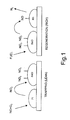
- Figure 1 shows the adsorption and reduction mechanism of a nitric oxide adsorber.
- the nitric oxide adsorption and reduction mechanism commences, as stated, in lean air-fuel mixture conditions, with oxidation of nitrogen monoxide (NO) into nitrogen dioxide ( NO 2 ) by the platinum (Pt) acting as a catalyst, according to the equation: N O + 1 2 O 2 ⁇ N O 2
- the nitrogen dioxide ( NO 2 ) reacts with the adsorbent element - barium oxide ( BaO ) in the example shown - by which it is trapped (i.e. chemically sorbed) in the form of barium nitrate ( Ba(NO 3 ) 2 ), according to the equation: Ba O + N O 2 + 1 2 O 2 ⁇ Ba ( N O 3 ) 2
- the air-fuel mixture is enriched for a predetermined time period to increase carbon monoxide and unburnt hydrocarbon emissions and impart reducing properties to the exhaust gas.
- nitrogen monoxide (NO) and nitrogen dioxide ( NO 2 ) are reduced by carbon monoxide (CO), hydrogen and hydrocarbons to nitrogen ( N 2 ) and carbon dioxide ( CO 2 ).
- a nitric oxide adsorber therefore substantially depends on the ability of barium to trap nitrogen dioxide, which in turn depends on various factors, such as exhaust gas temperature, exhaust gas flow, and the number of acceptor sites available in the barium. In the best possible operating conditions, a nitric oxide adsorber effectively eliminates as much as 90% of the nitric oxides produced by the engine.
- the fuel To prevent sulphates damaging the nitric oxide adsorber, the fuel must therefore contain no sulphur or, to limit the extent of damage, must contain at most 10 ppm.
- nitric oxide adsorber regeneration and accumulation cycle control strategies have been proposed, which comprise a fixed-duration (about 60-second) accumulation step, during which the air-fuel mixture is lean - in particular, assumes a value (A/F) of 20 to 55 - followed by a fixed-duration (about 5-second) regeneration step, during which the air-fuel mixture is enriched - in particular, assumes a value (A/F) of 12 to 14.
- Number 1 in Figure 2 indicates schematically and as a whole an internal combustion engine - in particular, a diesel engine - having an exhaust system 2, of which are shown only the parts required for a clear understanding of the present invention.
- Figure 2 shows, by way of a non-limiting example, a supercharged engine 1, i.e. comprising a turbosupercharger 3 defined by a compressor 4 located along an air intake manifold 5, and by a turbine 6 connected to compressor 4 and located along an exhaust manifold 7 of the engine.
- a supercharged engine i.e. comprising a turbosupercharger 3 defined by a compressor 4 located along an air intake manifold 5, and by a turbine 6 connected to compressor 4 and located along an exhaust manifold 7 of the engine.
- Exhaust system 2 comprises a nitric oxide (NO x ) adsorber 8 located along exhaust manifold 7; and an electronic control system 9 designed, among other things, to activate regeneration of nitric oxide adsorber 8 as described below.
- NO x nitric oxide
- electronic control system 9 comprises an airflow meter or so-called debimeter 10 located along air intake manifold 5 to measure the air intake Q A of the engine; a temperature sensor 11 located along exhaust manifold 7, at the inlet or outlet of nitric oxide adsorber 8, to measure the temperature T G of the exhaust gas flowing through nitric oxide adsorber 8; a measuring device 12 for measuring engine speed RPM and defined by a pulse wheel 13 fitted to the drive shaft 14 (shown schematically by the dash-and-dot line), and by an electromagnetic sensor 15 facing pulse wheel 13; and an electronic central control unit 16 connected to debimeter 10, to temperature sensor 11, and to measuring device 12, and implementing, among other things, the method of activating regeneration of nitric oxide adsorber 8 according to the invention.
- debimeter 10 located along air intake manifold 5 to measure the air intake Q A of the engine
- a temperature sensor 11 located along exhaust manifold 7, at the inlet or outlet of nitric oxide adsorber 8, to measure the temperature T G
- Figure 3 shows a block diagram illustrating the principle of the method of activating regeneration of nitric oxide adsorber 8 implemented by electronic central control unit 16.
- the regeneration activating method according to the invention is substantially based on determining a regeneration index indicating the residual adsorption capacity of the adsorber; comparing the regeneration index with a threshold indicating a minimum residual adsorption capacity; and activating regeneration of the nitric oxide adsorber when the regeneration index exceeds the threshold.
- the regeneration activating method according to the invention substantially comprises:
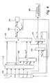
- Figure 4 shows a more detailed block diagram of the regeneration activating method according to the present invention. More specifically, the operations described below are repeated periodically at a frequency related to the clock frequency of electronic central control unit 16, e.g. every 65 ms, and are therefore described with reference to one execution.
- electronic central control unit 16 first acquires (block 200):
- Electronic central control unit 16 also stores the following constants or constant vectors/matrixes, which are calibrated as a function of physical characteristics of nitric oxide adsorber 8 (block 200):
- Electronic central control unit 16 then computes (block 210):
- flow Q NOx of the nitric oxides ( NO X ) produced by combustion is calculated by interpolation on the basis of an interpolation map based on engine bench tests, stored in electronic central control unit 16, and containing test-bench nitric oxide ( NO X ) flow Q NOx values as a function of engine speed RPM and torque TQ .
- Temperature and flow constants K T and K Q assume values of 0 to 1, and are calculated respectively as a function of exhaust gas temperature T G and flow Q G , as described below.
- temperature and flow constants K T and K Q are determined experimentally by feeding a given quantity of nitrogen monoxide (NO) to the nitric oxide adsorber inlet, and measuring the quantity of nitrogen monoxide (NO), nitrogen dioxide ( NO 2 ), and nitric oxides ( NO X ) at the outlet of nitric oxide adsorber 8.
- NO nitrogen monoxide
- NO 2 nitrogen dioxide
- NO X nitric oxides
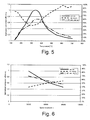
- Figure 5 shows nitrogen monoxide (NO) to nitrogen dioxide ( NO 2 ) conversion efficiency as a function of exhaust gas temperature T G . More specifically, Figure 5 shows the normalized ratio between the quantity of nitrogen dioxide ( NO 2 ) and nitrogen monoxide (NO) as a function of exhaust gas temperature T G , which may be used to calibrate temperature constant or constant vector/matrix K T .
- Figure 6 shows nitrogen monoxide (NO) to nitrogen dioxide ( NO 2 ) conversion efficiency as a function of exhaust gas space velocity Q G . More specifically, Figure 6 shows the normalized ratio between the quantity of nitrogen dioxide ( NO 2 ) and nitrogen monoxide (NO) as a function of exhaust gas space velocity Q G .
- Concentration constant or constant vector/matrix K C assumes values of 0 to 1, and is calculated as a function of constant C Pt proportional to the concentration of platinum in nitric oxide adsorber 8. Constant K C acts on oxidation conversion percentage absolute values, and as a weight applied to the constants described previously, and its value is determined by test comparisons of the inefficiency of different catalytic formulations with decreasing platinum loads.
- M NO2 (t) M N O X ⁇ N O 2 ( t ) ⁇ K T ⁇ K Q ⁇ K C ⁇ I REG
- M NO2 (i) M N O 2 ( i ⁇ 1 ) + M N O 2 ( t )
- the quantity M NO2 (i) of nitrogen dioxide ( NO 2 ) adsorbed is then memorized (block 260), and represents the quantity M NO2 (i-1) used in the next computing cycle to compute the next regeneration index I REG and the next quantity M NO2 (i) of nitrogen dioxide ( NO 2 ) adsorbed.
- Regeneration index I REG is then compared with a regeneration threshold I TH (block 270) : if I REG is greater than I TH , this means not all the nitric oxide adsorber acceptor sites are saturated, so that regeneration of nitric oxide adsorber 8 is not yet indispensable, and the entire computing cycle described above is repeated; conversely, when I REG is equal to or less than I TH , the adsorption capacity of the acceptor sites of nitric oxide adsorber 8 is considered nil, and regeneration of the nitric oxide adsorber is therefore activated as described initially, i.e. by enriching the air-fuel mixture to a value (A/F) of 12 to 14 (block 280) .
- A/F value
- Regeneration threshold I TH is determined as a function of the instantaneous adsorption efficiency of nitric oxide adsorber 8, as described below with reference to Figure 7, which shows a time graph of nitric oxide concentration at the outlet of nitric oxide adsorber 8.
- the graph comprises a substantially straight initial portion, in which nitric oxide concentration increases steadily with time (i.e. the instantaneous adsorption efficiency of nitric oxide adsorber 8 decreases steadily with time), followed by a portion which tends towards an asymptote represented by the nitric oxide concentration at the inlet of nitric oxide adsorber 8 (i.e.
- nitric oxide adsorber 8 decreases with time, tending asymptotically towards zero). From the chemical-physical standpoint, at the straight initial portion, nitric oxides are substantially adsorbed in sites close to the barium oxide layer surface, whereas, at the next asymptotic portion, nitric oxides are adsorbed in sites lower down and therefore dependent on gas permeability dynamics.
- Regeneration threshold I TH is therefore made equal to the quantity of nitric oxides adsorbed by nitric oxide adsorber 8 in a time interval, measured as of regeneration, equal to the duration of the straight portion of the Figure 7 curve, which is computed by integrating nitric oxide flow through nitric oxide adsorber 8 for a time equal to the duration of the straight portion of the Figure 7 curve.
- the duration of the accumulation stage depends on the actual degree of saturation of the nitric oxide adsorber acceptor sites, so that the adsorber is only regenerated when actually saturated.
- the regeneration index may be calculated differently, and in particular may be equal to the ratio between the quantity of nitrogen dioxide ( NO 2 ) adsorbed by the nitric oxide adsorber, and the maximum adsorption capacity ( C MAX ) of the nitric oxide adsorber.
- nitric oxide ( NO X ) flow Q NOx through nitric oxide adsorber 8 may be computed on the basis of nitric oxide concentration in exhaust gas flow through nitric oxide adsorber 8; which concentration may, for example, be measured by a nitric oxide sensor, indicated 17 in Figure 2, located along exhaust manifold 7, at the inlet or outlet of nitric oxide adsorber 8. More specifically, nitric oxide ( NO X ) flow Q NOx may be calculated as a portion of total exhaust gas flow, on the basis of the nitric oxide concentration percentage indicated by sensor 17.
- nitric oxide ( NO X ) flow Q NOX calculated on the basis of nitric oxide concentration measured by sensor 17 may be used solely to validate/check nitric oxide ( NO X ) flow calculated on the basis of engine quantities and characteristic parameters of nitric oxide adsorber 8.
Landscapes
- Chemical & Material Sciences (AREA)
- Engineering & Computer Science (AREA)
- Sustainable Development (AREA)
- Health & Medical Sciences (AREA)
- Biomedical Technology (AREA)
- Environmental & Geological Engineering (AREA)
- Life Sciences & Earth Sciences (AREA)
- Analytical Chemistry (AREA)
- General Chemical & Material Sciences (AREA)
- Oil, Petroleum & Natural Gas (AREA)
- Chemical Kinetics & Catalysis (AREA)
- Solid-Sorbent Or Filter-Aiding Compositions (AREA)
- Exhaust Gas After Treatment (AREA)
Abstract
Description
- The present invention relates to a method of activating regeneration of a nitric oxide adsorber.
- As is known, diesel engine emissions comprise the following compounds, some of which are harmful to health and/or the environment:
- carbon dioxide (CO 2 ) and steam (H 2 O), both produced by complete combustion of hydrocarbons in diesel fuel;
- unburnt hydrocarbons (HC) and carbon monoxide (CO), both produced by incomplete combustion of hydrocarbons in diesel fuel;
- nitric oxides (NO X ) produced by oxidation of nitrogen in the engine air intake; and
- particulate, mainly produced by incomplete combustion of the injected fuel.
- Carbon monoxide and hydrocarbons are convertible to carbon dioxide and steam by the following oxidation process, which is active when the air-fuel mixture is lean, i.e. high in oxygen:

- Nitric oxides, on the other hand, are convertible to carbon dioxide, nitrogen, and steam by the following reduction process, which is effective when the air-fuel mixture is rich:

- Otto engines can exploit the above phenomena simultaneously.
- To effectively eliminate all three of the above pollutants (HC, CO, NO X ), the air-fuel mixture in the combustion chamber of Otto engines equipped with a trivalent catalyst must be stoichiometric, i.e. the amount of air fed into the combustion chamber must be the exact amount required to burn the fuel in the combustion chamber.
- Trivalent catalysts, however, are unsuitable for use in diesel engines, operation of which calls for an air quantity in excess of stoichiometric proportions (lean operation), thus preventing reduction of nitric oxides in normal operating conditions, for the reasons stated above.
- Nitric oxides produced by diesel engines, therefore, cannot be eliminated using a trivalent catalyst, and the effectiveness of a catalyst in this type of engine is limited solely to oxidizing carbon monoxide and hydrocarbons into carbon dioxide and steam.
- In diesel engines, nitric oxides may be eliminated using a so-called nitric oxide adsorber, whereby, during normal operation of the engine, nitrogen monoxide (NO) is converted to nitrogen dioxide (NO 2 ) by an oxidizing element, e.g. platinum (Pt), is then trapped in an adsorbent compound, e.g. barium oxide (BaO), and is separated, at a specific operating stage, into nitrogen and carbon dioxide by a reducing element, e.g. rhodium (Rh). The operating stage, known as regeneration, is achieved by calibrating the diesel engine to produce a reducing environment (rich operation) in the exhaust gas for a few seconds.
- During the adsorption process, the barium oxide ultimately becomes unable to store nitrogen monoxide (NO), on account of saturation of the acceptor sites; and, when the nitric oxide adsorber reaches a saturation level at which nitric oxides are no longer eliminated effectively, the acceptor sites must be "cleared" periodically by so-called regeneration, i.e. desorption and simultaneous reduction of nitric oxides.
- As stated, nitric oxide adsorption and deadsorption are closely related to the composition of the air-fuel mixture during operation of the engine. That is, to adsorb nitric oxides, the air-fuel mixture must be lean (i.e. oxidizing), whereas, to desorb and reduce nitric oxides, the air-fuel mixture must be rich (i.e. reducing).
- Figure 1 shows the adsorption and reduction mechanism of a nitric oxide adsorber.
- More specifically, the nitric oxide adsorption and reduction mechanism commences, as stated, in lean air-fuel mixture conditions, with oxidation of nitrogen monoxide (NO) into nitrogen dioxide (NO 2 ) by the platinum (Pt) acting as a catalyst, according to the equation:

- Subsequently, the nitrogen dioxide (NO 2 ) reacts with the adsorbent element - barium oxide (BaO) in the example shown - by which it is trapped (i.e. chemically sorbed) in the form of barium nitrate (Ba(NO 3 ) 2 ), according to the equation:

- At the regeneration stage, the air-fuel mixture is enriched for a predetermined time period to increase carbon monoxide and unburnt hydrocarbon emissions and impart reducing properties to the exhaust gas.
- The reducing atmosphere produces thermodynamic instability in the barium nitrate, which thus releases nitrogen monoxide (NO) and nitrogen dioxide (NO 2 ), according to the equations:


- In rich air-fuel mixture conditions, and thanks to the presence of rhodium as a catalyst, nitrogen monoxide (NO) and nitrogen dioxide (NO 2 ) are reduced by carbon monoxide (CO), hydrogen and hydrocarbons to nitrogen (N 2 ) and carbon dioxide (CO 2 ).
- One possible reduction path is the equation:

- The success of the process depends directly on the air-fuel mixture, and, to effectively eliminate nitric oxides, the air/fuel proportion must be monitored continuously.
- Efficient operation of a nitric oxide adsorber therefore substantially depends on the ability of barium to trap nitrogen dioxide, which in turn depends on various factors, such as exhaust gas temperature, exhaust gas flow, and the number of acceptor sites available in the barium. In the best possible operating conditions, a nitric oxide adsorber effectively eliminates as much as 90% of the nitric oxides produced by the engine.
- One of the factors responsible for the reduction in adsorption capacity of barium is the presence of sulphur in the fuel. Unfortunately, at temperatures of over 300°C, sulphur oxidizes to sulphur dioxide (SO 2 ), which in turn may be converted by humidity in the atmosphere to sulphur trioxide (SO 3 ); which compounds react with barium oxide in the same way as nitrogen dioxide, i.e. tend to be trapped in the barium acceptor sites in the form of barium sulphate (BaSO 4 ), so that some of the acceptor sites are permanently occupied by barium sulphate, thus preventing entrapment of part of the nitrogen dioxide, and so impairing adsorber efficiency. In fact, unlike regeneration of acceptor sites saturated with nitrogen dioxide, which occurs between 300 and 450°C, regeneration of sulphate-saturated acceptor sites requires temperatures of around 600°C.
- To prevent sulphates damaging the nitric oxide adsorber, the fuel must therefore contain no sulphur or, to limit the extent of damage, must contain at most 10 ppm.
- Though slow, sulphate accumulation in the adsorber is therefore inevitable, on account of small quantities being derived anyway from the lubricating oil as well as the fuel, and must be removed periodically, every 1000-4000 km, by a specific regeneration strategy combining reducing environment conditions and temperature levels of around 600°C.
- The regeneration strategy of a nitric oxide adsorber is therefore clearly one of the major problems posed by automotive use of this type of catalyst.
- For this purpose, nitric oxide adsorber regeneration and accumulation cycle control strategies have been proposed, which comprise a fixed-duration (about 60-second) accumulation step, during which the air-fuel mixture is lean - in particular, assumes a value (A/F) of 20 to 55 - followed by a fixed-duration (about 5-second) regeneration step, during which the air-fuel mixture is enriched - in particular, assumes a value (A/F) of 12 to 14.
- Controlling nitric oxide adsorber accumulation and regeneration cycles as described above, however, is unsatisfactory in terms of consumption and pollutant emissions, by regeneration possibly being performed when not strictly necessary, or, conversely, not being performed when actually required.
- It is an object of the present invention to provide a method of activating regeneration of a nitric oxide adsorber, designed to eliminate the drawbacks of known methods.
- According to the present invention, there is provided a method of activating regeneration of a nitric oxide adsorber, as claimed in Claim 1.
- A preferred, non-limiting embodiment of the present invention will be described by way of example with reference to the accompanying drawings, in which:
- Figure 1 shows the nitric oxide adsorption and reduction mechanism of a nitric oxide adsorber;
- Figure 2 shows, schematically, an internal combustion engine exhaust system equipped with a nitric oxide adsorber;
- Figure 3 shows a block diagram illustrating the principle of the method of activating regeneration of a nitric oxide adsorber according to the invention;
- Figure 4 shows a more detailed block diagram of the regeneration activating method according to the invention;
- Figures 5, 6 and 7 show graphs of quantities involved in the regeneration activating method according to the invention.
- Number 1 in Figure 2 indicates schematically and as a whole an internal combustion engine - in particular, a diesel engine - having an
exhaust system 2, of which are shown only the parts required for a clear understanding of the present invention. - Figure 2 shows, by way of a non-limiting example, a supercharged engine 1, i.e. comprising a
turbosupercharger 3 defined by acompressor 4 located along anair intake manifold 5, and by aturbine 6 connected tocompressor 4 and located along anexhaust manifold 7 of the engine. -
Exhaust system 2 comprises a nitric oxide (NOx)adsorber 8 located alongexhaust manifold 7; and anelectronic control system 9 designed, among other things, to activate regeneration ofnitric oxide adsorber 8 as described below. - More specifically,
electronic control system 9 comprises an airflow meter or so-calleddebimeter 10 located alongair intake manifold 5 to measure the air intake Q A of the engine; atemperature sensor 11 located alongexhaust manifold 7, at the inlet or outlet ofnitric oxide adsorber 8, to measure the temperature T G of the exhaust gas flowing throughnitric oxide adsorber 8; ameasuring device 12 for measuring engine speed RPM and defined by apulse wheel 13 fitted to the drive shaft 14 (shown schematically by the dash-and-dot line), and by anelectromagnetic sensor 15 facingpulse wheel 13; and an electroniccentral control unit 16 connected todebimeter 10, totemperature sensor 11, and to measuringdevice 12, and implementing, among other things, the method of activating regeneration of nitric oxide adsorber 8 according to the invention. - Figure 3 shows a block diagram illustrating the principle of the method of activating regeneration of
nitric oxide adsorber 8 implemented by electroniccentral control unit 16. - Briefly, the regeneration activating method according to the invention is substantially based on determining a regeneration index indicating the residual adsorption capacity of the adsorber; comparing the regeneration index with a threshold indicating a minimum residual adsorption capacity; and activating regeneration of the nitric oxide adsorber when the regeneration index exceeds the threshold.
- More specifically, as shown in Figure 3, the regeneration activating method according to the invention substantially comprises:
- determining nitric oxide (NO X ) flow through
nitric oxide adsorber 8, as a function of a number of engine quantities and characteristic parameters ofnitric oxide adsorber 8, as described in detail below with reference to Figure 4 (block 100); - computing the nitric oxide (NO X ) quantity converted into nitrogen dioxide (NO 2 ) (block 110), as a function of a number of engine quantities and characteristic parameters of
nitric oxide adsorber 8; - computing the nitrogen dioxide (NO 2 ) quantity adsorbed by nitric oxide adsorber 8 (block 120), as a function of a number of engine quantities and characteristic parameters of
nitric oxide adsorber 8; - computing a regeneration index I REG indicating the residual adsorption capacity of the nitric oxide adsorber (block 130);
- comparing regeneration index I REC with a regeneration threshold I TH indicating the minimum permissible residual adsorption capacity of
nitric oxide adsorber 8 determined as described below with reference to Figure 7 (block 140); and - activating regeneration of the nitric oxide adsorber when regeneration index I REC is less than or equal to regeneration threshold I TH (block 150).
- Figure 4 shows a more detailed block diagram of the regeneration activating method according to the present invention. More specifically, the operations described below are repeated periodically at a frequency related to the clock frequency of electronic
central control unit 16, e.g. every 65 ms, and are therefore described with reference to one execution. - More specifically, as shown in Figure 4, electronic
central control unit 16 first acquires (block 200): - exhaust gas temperature T G , and
- engine speed RPM,
- engine torque TQ as a function of engine speed RPM supplied by measuring
device 12, and - mass exhaust gas flow Q G as the sum of air intake Q A supplied by
debimeter 10, and the total quantity of fuel injected, which is known by electroniccentral control unit 16. - Electronic
central control unit 16 also stores the following constants or constant vectors/matrixes, which are calibrated as a function of physical characteristics of nitric oxide adsorber 8 (block 200): - a constant C Pt proportional to the concentration of the oxidizing element - in the example considered, platinum (Pt) - in
nitric oxide adsorber 8; - the maximum adsorption capacity C MAX , in grams of nitrogen dioxide (NO 2 ), of
nitric oxide adsorber 8, which, in a first-order model, may be considered substantially constant with time, and, in a second-order model, may be considered variable - in particular, may decrease - with time because of ageing ofnitric oxide adsorber 8 and sulphate accumulation; and - a regeneration threshold I TH used as described below.
- Electronic
central control unit 16 then computes (block 210): - the flow Q NOx , in grams per hour (g/h), of nitric oxides (NO X ) produced by combustion, as a function of speed RPM and engine torque TQ;
- a temperature constant or constant vector/matrix K T , indicating nitric oxide (NO X ) to nitrogen dioxide (NO 2 ) conversion efficiency, as a function of temperature T G of the exhaust gas through
nitric oxide adsorber 8; - a flow constant or constant vector/matrix K Q , indicating nitric oxide (NO X ) to nitrogen dioxide (NO 2 ) conversion efficiency, as a function of exhaust gas flow Q G through
nitric oxide adsorber 8; and - a concentration constant or constant vector/matrix K C , indicating nitric oxide (NO X ) to nitrogen dioxide (NO 2 ) conversion efficiency, as a function of constant C Pt proportional to the concentration of platinum in
nitric oxide adsorber 8. - More specifically, flow Q NOx of the nitric oxides (NO X ) produced by combustion is calculated by interpolation on the basis of an interpolation map based on engine bench tests, stored in electronic
central control unit 16, and containing test-bench nitric oxide (NO X ) flow Q NOx values as a function of engine speed RPM and torque TQ. - Temperature and flow constants K T and K Q assume values of 0 to 1, and are calculated respectively as a function of exhaust gas temperature T G and flow Q G , as described below.
- More specifically, temperature and flow constants K T and K Q are determined experimentally by feeding a given quantity of nitrogen monoxide (NO) to the nitric oxide adsorber inlet, and measuring the quantity of nitrogen monoxide (NO), nitrogen dioxide (NO 2 ), and nitric oxides (NO X ) at the outlet of
nitric oxide adsorber 8. - Figure 5 shows nitrogen monoxide (NO) to nitrogen dioxide (NO 2 ) conversion efficiency as a function of exhaust gas temperature T G . More specifically, Figure 5 shows the normalized ratio between the quantity of nitrogen dioxide (NO 2 ) and nitrogen monoxide (NO) as a function of exhaust gas temperature T G , which may be used to calibrate temperature constant or constant vector/matrix K T .
- Figure 6 shows nitrogen monoxide (NO) to nitrogen dioxide (NO 2 ) conversion efficiency as a function of exhaust gas space velocity Q G . More specifically, Figure 6 shows the normalized ratio between the quantity of nitrogen dioxide (NO 2 ) and nitrogen monoxide (NO) as a function of exhaust gas space velocity Q G . Flow constant KQ may therefore be calculated as a function of the normalized ratio according to the equation:

- Concentration constant or constant vector/matrix K C assumes values of 0 to 1, and is calculated as a function of constant C Pt proportional to the concentration of platinum in
nitric oxide adsorber 8. Constant K C acts on oxidation conversion percentage absolute values, and as a weight applied to the constants described previously, and its value is determined by test comparisons of the inefficiency of different catalytic formulations with decreasing platinum loads. - With reference to Figure 4, the quantity M NOx->NO2 (t) in grams of nitric oxides (NO X ) converted to nitrogen dioxide (NO 2 ) in the time interval t since the preceding computing cycle, i.e. over the last 65 ms, is then computed (block 220), according to the equation:

- Regeneration index I REG is then computed (block 230) according to the equation:

where: - M NO2 (i-1) is the quantity of nitrogen dioxide (NO 2 ) in grams adsorbed by the nitric oxide adsorber since the last regeneration and up to the preceding computing cycle, and which is computed as described below.
- As shown clearly in the equation, regeneration index I REG may assume values of 0 to 1. More specifically, as soon as the nitric oxide adsorber is regenerated, NO 2 (i-1) = 0, so that I REC = 1; whereas, when the nitric oxide adsorber is saturated, i.e. when the quantity of nitric oxides adsorbed reaches maximum adsorption capacity, NO 2 (i -1) = C MAX , so that I REG = 0.
- Given regeneration index I REG , the quantity M NO2 (t), in grams, of nitrogen dioxide (NO 2 ) adsorbed by the nitric oxide adsorber in the current computing cycle, i.e. over the last 65 ms, is then computed (block 240), according to the equation:

- The quantity M NO2 (i), in grams, of nitrogen dioxide (NO 2 ) adsorbed by the nitric oxide adsorber since the last regeneration and up to the current computing cycle is then computed (block 250), according to the equation:

- The quantity M NO2 (i) of nitrogen dioxide (NO 2 ) adsorbed is then memorized (block 260), and represents the quantity M NO2 (i-1) used in the next computing cycle to compute the next regeneration index I REG and the next quantity M NO2 (i) of nitrogen dioxide (NO 2 ) adsorbed.
- Regeneration index I REG is then compared with a regeneration threshold I TH (block 270) : if I REG is greater than I TH , this means not all the nitric oxide adsorber acceptor sites are saturated, so that regeneration of
nitric oxide adsorber 8 is not yet indispensable, and the entire computing cycle described above is repeated; conversely, when I REG is equal to or less than I TH , the adsorption capacity of the acceptor sites ofnitric oxide adsorber 8 is considered nil, and regeneration of the nitric oxide adsorber is therefore activated as described initially, i.e. by enriching the air-fuel mixture to a value (A/F) of 12 to 14 (block 280) . - Regeneration threshold I TH is determined as a function of the instantaneous adsorption efficiency of
nitric oxide adsorber 8, as described below with reference to Figure 7, which shows a time graph of nitric oxide concentration at the outlet ofnitric oxide adsorber 8. As can be seen, the graph comprises a substantially straight initial portion, in which nitric oxide concentration increases steadily with time (i.e. the instantaneous adsorption efficiency ofnitric oxide adsorber 8 decreases steadily with time), followed by a portion which tends towards an asymptote represented by the nitric oxide concentration at the inlet of nitric oxide adsorber 8 (i.e. the instantaneous adsorption efficiency ofnitric oxide adsorber 8 decreases with time, tending asymptotically towards zero). From the chemical-physical standpoint, at the straight initial portion, nitric oxides are substantially adsorbed in sites close to the barium oxide layer surface, whereas, at the next asymptotic portion, nitric oxides are adsorbed in sites lower down and therefore dependent on gas permeability dynamics. - Regeneration threshold I TH is therefore made equal to the quantity of nitric oxides adsorbed by
nitric oxide adsorber 8 in a time interval, measured as of regeneration, equal to the duration of the straight portion of the Figure 7 curve, which is computed by integrating nitric oxide flow throughnitric oxide adsorber 8 for a time equal to the duration of the straight portion of the Figure 7 curve. - The advantages of the present invention will be clear from the foregoing description. In particular, as opposed to being fixed, the duration of the accumulation stage depends on the actual degree of saturation of the nitric oxide adsorber acceptor sites, so that the adsorber is only regenerated when actually saturated.
- Clearly, changes may be made to the method as described and illustrated herein without, however, departing from the scope of the present invention, as defined in the accompanying Claims.
- For example, the regeneration index may be calculated differently, and in particular may be equal to the ratio between the quantity of nitrogen dioxide (NO 2 ) adsorbed by the nitric oxide adsorber, and the maximum adsorption capacity (C MAX ) of the nitric oxide adsorber.
- Moreover, as opposed to being based on engine quantities and characteristic parameters of
nitric oxide adsorber 8, as described above, nitric oxide (NO X ) flow Q NOx throughnitric oxide adsorber 8 may be computed on the basis of nitric oxide concentration in exhaust gas flow throughnitric oxide adsorber 8; which concentration may, for example, be measured by a nitric oxide sensor, indicated 17 in Figure 2, located alongexhaust manifold 7, at the inlet or outlet ofnitric oxide adsorber 8. More specifically, nitric oxide (NO X ) flow Q NOx may be calculated as a portion of total exhaust gas flow, on the basis of the nitric oxide concentration percentage indicated bysensor 17. - Alternatively, nitric oxide (NO X ) flow Q NOX calculated on the basis of nitric oxide concentration measured by
sensor 17 may be used solely to validate/check nitric oxide (NO X ) flow calculated on the basis of engine quantities and characteristic parameters ofnitric oxide adsorber 8.
Claims (11)
- A method of activating regeneration of a nitric oxide adsorber (8), characterized by comprising:- determining a quantity indicating the quantity of nitric oxides (NO X ) adsorbed by said nitric oxide adsorber (8); and- activating regeneration of said nitric oxide adsorber (8) on the basis of the quantity of nitric oxides (NO X ) adsorbed.
- A method as claimed in Claim 1, wherein activating regeneration of said nitric oxide adsorber (8) comprises:- determining a regeneration index (I REG ) as a function of said quantity indicating the quantity of nitric oxides (NO X ) adsorbed by said nitric oxide adsorber (8);- comparing said regeneration index (I REG ) with a regeneration threshold (I TH ); and- activating regeneration of said nitric oxide adsorber (8) when said regeneration index (I REG ) and said regeneration threshold (I TH ) satisfy a predetermined relationship.
- A method as claimed in Claim 2, wherein said regeneration index (I REG ) is determined as a function of said quantity indicating the quantity of nitric oxides (NO X ) adsorbed by said nitric oxide adsorber (8), and of a quantity indicating the maximum adsorption capacity (C MAX ) of said nitric oxide adsorber (8).
- A method as claimed in Claim 2 or 3, wherein said regeneration index (I REG ) indicates the residual adsorption capacity of said nitric oxide adsorber (8), and said regeneration threshold (I TH ) indicates a minimum residual adsorption capacity of said nitric oxide adsorber (8); and wherein said predetermined relationship is the condition that said regeneration index (I REG ) is less than or equal to said regeneration threshold (I TH ).
- A method as claimed in any one of the foregoing Claims, wherein determining a quantity indicating the quantity of nitric oxides (NO X ) adsorbed by said nitric oxide adsorber (8) comprises:- determining a quantity indicating the flow of nitric oxides (NO X ) through said nitric oxide adsorber (8);- determining a quantity indicating the quantity of nitric oxides (NO X ) converted to nitrogen dioxide (NO 2 ) in said nitric oxide adsorber (8); and- determining a quantity indicating the quantity of nitrogen dioxide (NO 2 ) adsorbed by said nitric oxide adsorber (8).
- A method as claimed in Claim 5, wherein determining a quantity indicating the quantity of nitric oxides (NO X ) converted to nitrogen dioxide (NO 2 ) in said nitric oxide adsorber (8) comprises:- determining a conversion efficiency (K T , K Q , K Pt ) of nitric oxides (NO X ) to nitrogen dioxide (NO 2 ) in said nitric oxide adsorber (8); and- determining said quantity, indicating the quantity of nitric oxides (NO X ) converted to nitrogen dioxide (NO 2 ) in said nitric oxide adsorber (8), as a function of said quantity indicating the flow of nitric oxides (NO X ) through said nitric oxide adsorber (8), and of said conversion efficiency (K T , K Q , K Pt ).
- A method as claimed in Claim 6, for a nitric oxide adsorber (8) located along an exhaust gas manifold (7) of an internal combustion engine (1), wherein determining the conversion efficiency (K T , K Q , K Pt ) of nitric oxides (NO X ) to nitrogen dioxide (NO 2 ) in said nitric oxide adsorber (8) comprises:- determining exhaust gas temperature (T G );- determining exhaust gas flow (Q G );- determining a temperature constant or constant vector/matrix (K T ), indicating the conversion efficiency of nitric oxides (NO X ) to nitrogen dioxide (NO 2 ), as a function of exhaust gas temperature (T G );- determining a flow constant or constant vector/matrix (K Q ), indicating the conversion efficiency of nitric oxides (NO X ) to nitrogen dioxide (NO 2 ), as a function of exhaust gas flow (Q G );- determining a concentration constant or constant vector/matrix (K C ), indicating the conversion efficiency of nitric oxides (NO X ) to nitrogen dioxide (NO 2 ), as a function of the concentration (C Pt ) of an oxidizing element (Pt) in said nitric oxide adsorber (8).
- A method as claimed in Claim 7, wherein said quantity indicating the quantity of nitrogen dioxide (NO 2 ) adsorbed by said nitric oxide adsorber (8) is determined as a function of said quantity indicating the quantity of nitric oxides (NO X ) converted to nitrogen dioxide (NO 2 ) in said nitric oxide adsorber (8), of said temperature constant or constant vector/matrix (K T ), of said flow constant or constant vector/matrix (K Q ), and of said regeneration index (I REG ).
- A method as claimed in Claim 7 or 8, wherein determining said quantity indicating the quantity of nitrogen dioxide (NO 2 ) adsorbed by said nitric oxide adsorber (8) comprises:- determining a quantity, indicating the quantity of nitric oxides (NO X ) converted to nitrogen dioxide (NO 2 ) in said nitric oxide adsorber (8) in a given time interval (t), as a function of said quantity indicating the flow of nitric oxides (NO X ) through said nitric oxide adsorber (8), of said temperature constant or constant vector/matrix (K T ), of said flow constant or constant vector/matrix (K Q ), and of said concentration constant or constant vector/matrix (K C );- determining a quantity, indicating the quantity of nitrogen dioxide (NO 2 ) adsorbed by said nitric oxide adsorber (8) in said time interval (t), as a function of said quantity indicating the quantity of nitric oxides (NO X ) converted to nitrogen dioxide (NO 2 ) in said nitric oxide adsorber (8) in said time interval (t), of said temperature constant or constant vector/matrix (K T ), of said flow constant or constant vector/matrix (K Q ), and of said regeneration index (I REG ); and- determining said quantity, indicating the quantity of nitrogen dioxide (NO 2 ) adsorbed by said nitric oxide adsorber (8), as a function of said quantity indicating the quantity of nitrogen dioxide (NO 2 ) adsorbed by said nitric oxide adsorber (8) in said time interval (t), and of a quantity indicating the quantity of nitrogen dioxide (NO 2 ) previously adsorbed by said nitric oxide adsorber (8) .
- A method as claimed in any one of Claims 5 to 9, wherein determining a quantity indicating the flow of nitric oxides (NO X ) through said nitric oxide adsorber (8) comprises:- determining the speed (RPM) of said engine (1);- determining the torque (TQ) of said engine (1); and- determining said quantity, indicating the flow of nitric oxides (NO X ) through said nitric oxide adsorber (8), as a function of the speed (RPM) and torque (TQ) of said engine (1).
- A method as claimed in any one of Claims 5 to 9, wherein determining a quantity indicating the flow of nitric oxides (NO X ) through said nitric oxide adsorber (8) comprises:- measuring the concentration of nitric oxides through said nitric oxide adsorber (8); and- determining said quantity, indicating the flow of nitric oxides (NO X ) through said nitric oxide adsorber (8), as a function of the measured concentration of nitric oxides.
Priority Applications (3)
| Application Number | Priority Date | Filing Date | Title |
|---|---|---|---|
| DE602005021049T DE602005021049D1 (en) | 2005-03-02 | 2005-03-02 | Method for activating the regeneration of a NOx adsorber |
| AT05425115T ATE467037T1 (en) | 2005-03-02 | 2005-03-02 | METHOD FOR ACTIVATING THE REGENERATION OF A NOX ADSORBER |
| EP05425115A EP1698767B1 (en) | 2005-03-02 | 2005-03-02 | Method of activating regeneration of a nitric oxide adsorber |
Applications Claiming Priority (1)
| Application Number | Priority Date | Filing Date | Title |
|---|---|---|---|
| EP05425115A EP1698767B1 (en) | 2005-03-02 | 2005-03-02 | Method of activating regeneration of a nitric oxide adsorber |
Publications (2)
| Publication Number | Publication Date |
|---|---|
| EP1698767A1 true EP1698767A1 (en) | 2006-09-06 |
| EP1698767B1 EP1698767B1 (en) | 2010-05-05 |
Family
ID=34943076
Family Applications (1)
| Application Number | Title | Priority Date | Filing Date |
|---|---|---|---|
| EP05425115A Expired - Lifetime EP1698767B1 (en) | 2005-03-02 | 2005-03-02 | Method of activating regeneration of a nitric oxide adsorber |
Country Status (3)
| Country | Link |
|---|---|
| EP (1) | EP1698767B1 (en) |
| AT (1) | ATE467037T1 (en) |
| DE (1) | DE602005021049D1 (en) |
Citations (5)
| Publication number | Priority date | Publication date | Assignee | Title |
|---|---|---|---|---|
| EP0580389A1 (en) * | 1992-07-24 | 1994-01-26 | Toyota Jidosha Kabushiki Kaisha | Exhaust gas purification apparatus for an internal combustion engine |
| US5771685A (en) * | 1996-10-16 | 1998-06-30 | Ford Global Technologies, Inc. | Method for monitoring the performance of a NOx trap |
| EP0997626A1 (en) * | 1998-10-28 | 2000-05-03 | Renault | Method to control the purging of nitrogen oxides from an exhaust gas catalytic converter of an internal combustion engine |
| EP1083306A1 (en) * | 1999-09-07 | 2001-03-14 | MAGNETI MARELLI S.p.A. | Self-adapting control method for an exhaust system for internal combustion engines with controlled ignition |
| EP1402935A1 (en) * | 2002-09-20 | 2004-03-31 | Ford Global Technologies, Inc. | Filter diagnostics method and arrangement |
-
2005
- 2005-03-02 DE DE602005021049T patent/DE602005021049D1/en not_active Expired - Lifetime
- 2005-03-02 EP EP05425115A patent/EP1698767B1/en not_active Expired - Lifetime
- 2005-03-02 AT AT05425115T patent/ATE467037T1/en not_active IP Right Cessation
Patent Citations (5)
| Publication number | Priority date | Publication date | Assignee | Title |
|---|---|---|---|---|
| EP0580389A1 (en) * | 1992-07-24 | 1994-01-26 | Toyota Jidosha Kabushiki Kaisha | Exhaust gas purification apparatus for an internal combustion engine |
| US5771685A (en) * | 1996-10-16 | 1998-06-30 | Ford Global Technologies, Inc. | Method for monitoring the performance of a NOx trap |
| EP0997626A1 (en) * | 1998-10-28 | 2000-05-03 | Renault | Method to control the purging of nitrogen oxides from an exhaust gas catalytic converter of an internal combustion engine |
| EP1083306A1 (en) * | 1999-09-07 | 2001-03-14 | MAGNETI MARELLI S.p.A. | Self-adapting control method for an exhaust system for internal combustion engines with controlled ignition |
| EP1402935A1 (en) * | 2002-09-20 | 2004-03-31 | Ford Global Technologies, Inc. | Filter diagnostics method and arrangement |
Also Published As
| Publication number | Publication date |
|---|---|
| ATE467037T1 (en) | 2010-05-15 |
| DE602005021049D1 (en) | 2010-06-17 |
| EP1698767B1 (en) | 2010-05-05 |
Similar Documents
| Publication | Publication Date | Title |
|---|---|---|
| US7111451B2 (en) | NOx adsorber diagnostics and automotive exhaust control system utilizing the same | |
| US8555616B2 (en) | Identifying ammonia non-slip conditions in a selective catalytic reduction application | |
| US8341938B2 (en) | Method for determining the instant at which a nitrogen oxide storage catalyst is switched from the storage phase to the regeneration phase and for diagnosing the storage properties of this catalyst | |
| WO2008108499A1 (en) | APPARATUS FOR DIAGNOSING DETERIORATION OF NOx CATALYST | |
| CN110939501B (en) | Catalyst deterioration diagnosis system and catalyst deterioration diagnosis method | |
| US8739615B2 (en) | Device and method of determining deterioration of catalyst | |
| US6418711B1 (en) | Method and apparatus for estimating lean NOx trap capacity | |
| US7481046B2 (en) | Method of desulfating a NOx storage and conversion device | |
| JP7071246B2 (en) | Catalyst deterioration diagnosis method and catalyst deterioration diagnosis system | |
| EP3382172B1 (en) | Abnormality diagnosis apparatus for exhaust gas purification apparatus | |
| JP2006169997A (en) | Catalyst deterioration judgment device | |
| JP2009257231A (en) | Exhaust emission control device for internal combustion engine | |
| US9429088B2 (en) | Lean NOx trap desulfation process | |
| JP3674358B2 (en) | Exhaust gas purification device for internal combustion engine | |
| EP1698767B1 (en) | Method of activating regeneration of a nitric oxide adsorber | |
| US7219008B2 (en) | Method and device for estimating a nitrogen oxide mass stored in a catalytic trapping device of a motor vehicle | |
| US6978598B2 (en) | Deteriorated state evaluation device for exhaust emission control equipment | |
| JP2012031761A (en) | Catalyst abnormality diagnostic device | |
| EP1722086B1 (en) | Method of controlling air intake flow of an internal combustion engine, in particular for regenerating a nitric oxide adsorber | |
| US7614217B2 (en) | Method and device for activating regeneration of a nitric oxide adsorber | |
| JP3508703B2 (en) | Exhaust gas purification device for internal combustion engine | |
| JP3485076B2 (en) | Exhaust gas purification device for internal combustion engine | |
| GB2396122A (en) | A method for desulphating NOx traps and a method for sulphating an internal combustion engine emission control system under test conditions. |
Legal Events
| Date | Code | Title | Description |
|---|---|---|---|
| PUAI | Public reference made under article 153(3) epc to a published international application that has entered the european phase |
Free format text: ORIGINAL CODE: 0009012 |
|
| 17P | Request for examination filed |
Effective date: 20051219 |
|
| AK | Designated contracting states |
Kind code of ref document: A1 Designated state(s): AT BE BG CH CY CZ DE DK EE ES FI FR GB GR HU IE IS IT LI LT LU MC NL PL PT RO SE SI SK TR |
|
| AX | Request for extension of the european patent |
Extension state: AL BA HR LV MK YU |
|
| 17Q | First examination report despatched |
Effective date: 20070326 |
|
| AKX | Designation fees paid |
Designated state(s): AT BE BG CH CY CZ DE DK EE ES FI FR GB GR HU IE IS IT LI LT LU MC NL PL PT RO SE SI SK TR |
|
| GRAP | Despatch of communication of intention to grant a patent |
Free format text: ORIGINAL CODE: EPIDOSNIGR1 |
|
| GRAS | Grant fee paid |
Free format text: ORIGINAL CODE: EPIDOSNIGR3 |
|
| RIN1 | Information on inventor provided before grant (corrected) |
Inventor name: ASTI, MASSIMO Inventor name: MERLONE BORLA, EDOARDO Inventor name: FARALDI, PAOLO Inventor name: PIDRIA, MARCO FEDERICO |
|
| GRAA | (expected) grant |
Free format text: ORIGINAL CODE: 0009210 |
|
| AK | Designated contracting states |
Kind code of ref document: B1 Designated state(s): AT BE BG CH CY CZ DE DK EE ES FI FR GB GR HU IE IS IT LI LT LU MC NL PL PT RO SE SI SK TR |
|
| REG | Reference to a national code |
Ref country code: GB Ref legal event code: FG4D |
|
| REG | Reference to a national code |
Ref country code: CH Ref legal event code: EP |
|
| REG | Reference to a national code |
Ref country code: IE Ref legal event code: FG4D |
|
| REF | Corresponds to: |
Ref document number: 602005021049 Country of ref document: DE Date of ref document: 20100617 Kind code of ref document: P |
|
| REG | Reference to a national code |
Ref country code: NL Ref legal event code: VDEP Effective date: 20100505 |
|
| LTIE | Lt: invalidation of european patent or patent extension |
Effective date: 20100505 |
|
| PG25 | Lapsed in a contracting state [announced via postgrant information from national office to epo] |
Ref country code: SE Free format text: LAPSE BECAUSE OF FAILURE TO SUBMIT A TRANSLATION OF THE DESCRIPTION OR TO PAY THE FEE WITHIN THE PRESCRIBED TIME-LIMIT Effective date: 20100505 Ref country code: NL Free format text: LAPSE BECAUSE OF FAILURE TO SUBMIT A TRANSLATION OF THE DESCRIPTION OR TO PAY THE FEE WITHIN THE PRESCRIBED TIME-LIMIT Effective date: 20100505 Ref country code: LT Free format text: LAPSE BECAUSE OF FAILURE TO SUBMIT A TRANSLATION OF THE DESCRIPTION OR TO PAY THE FEE WITHIN THE PRESCRIBED TIME-LIMIT Effective date: 20100505 Ref country code: ES Free format text: LAPSE BECAUSE OF FAILURE TO SUBMIT A TRANSLATION OF THE DESCRIPTION OR TO PAY THE FEE WITHIN THE PRESCRIBED TIME-LIMIT Effective date: 20100816 |
|
| PG25 | Lapsed in a contracting state [announced via postgrant information from national office to epo] |
Ref country code: AT Free format text: LAPSE BECAUSE OF FAILURE TO SUBMIT A TRANSLATION OF THE DESCRIPTION OR TO PAY THE FEE WITHIN THE PRESCRIBED TIME-LIMIT Effective date: 20100505 Ref country code: SI Free format text: LAPSE BECAUSE OF FAILURE TO SUBMIT A TRANSLATION OF THE DESCRIPTION OR TO PAY THE FEE WITHIN THE PRESCRIBED TIME-LIMIT Effective date: 20100505 Ref country code: IS Free format text: LAPSE BECAUSE OF FAILURE TO SUBMIT A TRANSLATION OF THE DESCRIPTION OR TO PAY THE FEE WITHIN THE PRESCRIBED TIME-LIMIT Effective date: 20100905 Ref country code: FI Free format text: LAPSE BECAUSE OF FAILURE TO SUBMIT A TRANSLATION OF THE DESCRIPTION OR TO PAY THE FEE WITHIN THE PRESCRIBED TIME-LIMIT Effective date: 20100505 |
|
| PG25 | Lapsed in a contracting state [announced via postgrant information from national office to epo] |
Ref country code: CY Free format text: LAPSE BECAUSE OF FAILURE TO SUBMIT A TRANSLATION OF THE DESCRIPTION OR TO PAY THE FEE WITHIN THE PRESCRIBED TIME-LIMIT Effective date: 20100505 Ref country code: PL Free format text: LAPSE BECAUSE OF FAILURE TO SUBMIT A TRANSLATION OF THE DESCRIPTION OR TO PAY THE FEE WITHIN THE PRESCRIBED TIME-LIMIT Effective date: 20100505 Ref country code: GR Free format text: LAPSE BECAUSE OF FAILURE TO SUBMIT A TRANSLATION OF THE DESCRIPTION OR TO PAY THE FEE WITHIN THE PRESCRIBED TIME-LIMIT Effective date: 20100806 |
|
| PG25 | Lapsed in a contracting state [announced via postgrant information from national office to epo] |
Ref country code: PT Free format text: LAPSE BECAUSE OF FAILURE TO SUBMIT A TRANSLATION OF THE DESCRIPTION OR TO PAY THE FEE WITHIN THE PRESCRIBED TIME-LIMIT Effective date: 20100906 Ref country code: EE Free format text: LAPSE BECAUSE OF FAILURE TO SUBMIT A TRANSLATION OF THE DESCRIPTION OR TO PAY THE FEE WITHIN THE PRESCRIBED TIME-LIMIT Effective date: 20100505 Ref country code: DK Free format text: LAPSE BECAUSE OF FAILURE TO SUBMIT A TRANSLATION OF THE DESCRIPTION OR TO PAY THE FEE WITHIN THE PRESCRIBED TIME-LIMIT Effective date: 20100505 |
|
| PG25 | Lapsed in a contracting state [announced via postgrant information from national office to epo] |
Ref country code: RO Free format text: LAPSE BECAUSE OF FAILURE TO SUBMIT A TRANSLATION OF THE DESCRIPTION OR TO PAY THE FEE WITHIN THE PRESCRIBED TIME-LIMIT Effective date: 20100505 Ref country code: BE Free format text: LAPSE BECAUSE OF FAILURE TO SUBMIT A TRANSLATION OF THE DESCRIPTION OR TO PAY THE FEE WITHIN THE PRESCRIBED TIME-LIMIT Effective date: 20100505 Ref country code: CZ Free format text: LAPSE BECAUSE OF FAILURE TO SUBMIT A TRANSLATION OF THE DESCRIPTION OR TO PAY THE FEE WITHIN THE PRESCRIBED TIME-LIMIT Effective date: 20100505 Ref country code: SK Free format text: LAPSE BECAUSE OF FAILURE TO SUBMIT A TRANSLATION OF THE DESCRIPTION OR TO PAY THE FEE WITHIN THE PRESCRIBED TIME-LIMIT Effective date: 20100505 |
|
| PLBE | No opposition filed within time limit |
Free format text: ORIGINAL CODE: 0009261 |
|
| STAA | Information on the status of an ep patent application or granted ep patent |
Free format text: STATUS: NO OPPOSITION FILED WITHIN TIME LIMIT |
|
| 26N | No opposition filed |
Effective date: 20110208 |
|
| REG | Reference to a national code |
Ref country code: DE Ref legal event code: R097 Ref document number: 602005021049 Country of ref document: DE Effective date: 20110207 |
|
| PG25 | Lapsed in a contracting state [announced via postgrant information from national office to epo] |
Ref country code: MC Free format text: LAPSE BECAUSE OF NON-PAYMENT OF DUE FEES Effective date: 20110331 |
|
| REG | Reference to a national code |
Ref country code: CH Ref legal event code: PL |
|
| GBPC | Gb: european patent ceased through non-payment of renewal fee |
Effective date: 20110302 |
|
| REG | Reference to a national code |
Ref country code: IE Ref legal event code: MM4A |
|
| PG25 | Lapsed in a contracting state [announced via postgrant information from national office to epo] |
Ref country code: CH Free format text: LAPSE BECAUSE OF NON-PAYMENT OF DUE FEES Effective date: 20110331 Ref country code: LI Free format text: LAPSE BECAUSE OF NON-PAYMENT OF DUE FEES Effective date: 20110331 Ref country code: IE Free format text: LAPSE BECAUSE OF NON-PAYMENT OF DUE FEES Effective date: 20110302 |
|
| PG25 | Lapsed in a contracting state [announced via postgrant information from national office to epo] |
Ref country code: GB Free format text: LAPSE BECAUSE OF NON-PAYMENT OF DUE FEES Effective date: 20110302 |
|
| PGFP | Annual fee paid to national office [announced via postgrant information from national office to epo] |
Ref country code: FR Payment date: 20120319 Year of fee payment: 8 |
|
| PGFP | Annual fee paid to national office [announced via postgrant information from national office to epo] |
Ref country code: IT Payment date: 20120323 Year of fee payment: 8 |
|
| PGFP | Annual fee paid to national office [announced via postgrant information from national office to epo] |
Ref country code: DE Payment date: 20120404 Year of fee payment: 8 |
|
| PG25 | Lapsed in a contracting state [announced via postgrant information from national office to epo] |
Ref country code: LU Free format text: LAPSE BECAUSE OF NON-PAYMENT OF DUE FEES Effective date: 20110302 |
|
| PG25 | Lapsed in a contracting state [announced via postgrant information from national office to epo] |
Ref country code: BG Free format text: LAPSE BECAUSE OF FAILURE TO SUBMIT A TRANSLATION OF THE DESCRIPTION OR TO PAY THE FEE WITHIN THE PRESCRIBED TIME-LIMIT Effective date: 20100805 Ref country code: TR Free format text: LAPSE BECAUSE OF FAILURE TO SUBMIT A TRANSLATION OF THE DESCRIPTION OR TO PAY THE FEE WITHIN THE PRESCRIBED TIME-LIMIT Effective date: 20100505 |
|
| PG25 | Lapsed in a contracting state [announced via postgrant information from national office to epo] |
Ref country code: HU Free format text: LAPSE BECAUSE OF FAILURE TO SUBMIT A TRANSLATION OF THE DESCRIPTION OR TO PAY THE FEE WITHIN THE PRESCRIBED TIME-LIMIT Effective date: 20100505 |
|
| REG | Reference to a national code |
Ref country code: FR Ref legal event code: ST Effective date: 20131129 |
|
| REG | Reference to a national code |
Ref country code: DE Ref legal event code: R119 Ref document number: 602005021049 Country of ref document: DE Effective date: 20131001 |
|
| PG25 | Lapsed in a contracting state [announced via postgrant information from national office to epo] |
Ref country code: FR Free format text: LAPSE BECAUSE OF NON-PAYMENT OF DUE FEES Effective date: 20130402 Ref country code: DE Free format text: LAPSE BECAUSE OF NON-PAYMENT OF DUE FEES Effective date: 20131001 |
|
| PG25 | Lapsed in a contracting state [announced via postgrant information from national office to epo] |
Ref country code: IT Free format text: LAPSE BECAUSE OF NON-PAYMENT OF DUE FEES Effective date: 20130302 |