EP1698450A1 - A unit for embossing a strip of wrapping material - Google Patents
A unit for embossing a strip of wrapping material Download PDFInfo
- Publication number
- EP1698450A1 EP1698450A1 EP06110526A EP06110526A EP1698450A1 EP 1698450 A1 EP1698450 A1 EP 1698450A1 EP 06110526 A EP06110526 A EP 06110526A EP 06110526 A EP06110526 A EP 06110526A EP 1698450 A1 EP1698450 A1 EP 1698450A1
- Authority
- EP
- European Patent Office
- Prior art keywords
- embossing
- strip
- unit
- decoiling
- embossing unit
- Prior art date
- Legal status (The legal status is an assumption and is not a legal conclusion. Google has not performed a legal analysis and makes no representation as to the accuracy of the status listed.)
- Granted
Links
Images



Classifications
-
- B—PERFORMING OPERATIONS; TRANSPORTING
- B31—MAKING ARTICLES OF PAPER, CARDBOARD OR MATERIAL WORKED IN A MANNER ANALOGOUS TO PAPER; WORKING PAPER, CARDBOARD OR MATERIAL WORKED IN A MANNER ANALOGOUS TO PAPER
- B31F—MECHANICAL WORKING OR DEFORMATION OF PAPER, CARDBOARD OR MATERIAL WORKED IN A MANNER ANALOGOUS TO PAPER
- B31F1/00—Mechanical deformation without removing material, e.g. in combination with laminating
- B31F1/07—Embossing, i.e. producing impressions formed by locally deep-drawing, e.g. using rolls provided with complementary profiles
-
- B—PERFORMING OPERATIONS; TRANSPORTING
- B31—MAKING ARTICLES OF PAPER, CARDBOARD OR MATERIAL WORKED IN A MANNER ANALOGOUS TO PAPER; WORKING PAPER, CARDBOARD OR MATERIAL WORKED IN A MANNER ANALOGOUS TO PAPER
- B31F—MECHANICAL WORKING OR DEFORMATION OF PAPER, CARDBOARD OR MATERIAL WORKED IN A MANNER ANALOGOUS TO PAPER
- B31F2201/00—Mechanical deformation of paper or cardboard without removing material
- B31F2201/07—Embossing
- B31F2201/0779—Control
-
- B—PERFORMING OPERATIONS; TRANSPORTING
- B31—MAKING ARTICLES OF PAPER, CARDBOARD OR MATERIAL WORKED IN A MANNER ANALOGOUS TO PAPER; WORKING PAPER, CARDBOARD OR MATERIAL WORKED IN A MANNER ANALOGOUS TO PAPER
- B31F—MECHANICAL WORKING OR DEFORMATION OF PAPER, CARDBOARD OR MATERIAL WORKED IN A MANNER ANALOGOUS TO PAPER
- B31F2201/00—Mechanical deformation of paper or cardboard without removing material
- B31F2201/07—Embossing
- B31F2201/0784—Auxiliary operations
-
- B—PERFORMING OPERATIONS; TRANSPORTING
- B31—MAKING ARTICLES OF PAPER, CARDBOARD OR MATERIAL WORKED IN A MANNER ANALOGOUS TO PAPER; WORKING PAPER, CARDBOARD OR MATERIAL WORKED IN A MANNER ANALOGOUS TO PAPER
- B31F—MECHANICAL WORKING OR DEFORMATION OF PAPER, CARDBOARD OR MATERIAL WORKED IN A MANNER ANALOGOUS TO PAPER
- B31F2201/00—Mechanical deformation of paper or cardboard without removing material
- B31F2201/07—Embossing
- B31F2201/0784—Auxiliary operations
- B31F2201/0794—Cutting
-
- B—PERFORMING OPERATIONS; TRANSPORTING
- B65—CONVEYING; PACKING; STORING; HANDLING THIN OR FILAMENTARY MATERIAL
- B65B—MACHINES, APPARATUS OR DEVICES FOR, OR METHODS OF, PACKAGING ARTICLES OR MATERIALS; UNPACKING
- B65B19/00—Packaging rod-shaped or tubular articles susceptible to damage by abrasion or pressure, e.g. cigarettes, cigars, macaroni, spaghetti, drinking straws or welding electrodes
- B65B19/02—Packaging cigarettes
- B65B19/22—Wrapping the cigarettes; Packaging the cigarettes in containers formed by folding wrapping material around formers
- B65B19/228—Preparing and feeding blanks
-
- B—PERFORMING OPERATIONS; TRANSPORTING
- B65—CONVEYING; PACKING; STORING; HANDLING THIN OR FILAMENTARY MATERIAL
- B65B—MACHINES, APPARATUS OR DEVICES FOR, OR METHODS OF, PACKAGING ARTICLES OR MATERIALS; UNPACKING
- B65B61/00—Auxiliary devices, not otherwise provided for, for operating on sheets, blanks, webs, binding material, containers or packages
- B65B61/02—Auxiliary devices, not otherwise provided for, for operating on sheets, blanks, webs, binding material, containers or packages for perforating, scoring, slitting, or applying code or date marks on material prior to packaging
- B65B61/025—Auxiliary devices, not otherwise provided for, for operating on sheets, blanks, webs, binding material, containers or packages for perforating, scoring, slitting, or applying code or date marks on material prior to packaging for applying, e.g. printing, code or date marks on material prior to packaging
Definitions
- the present invention relates to a unit for embossing a strip of wrapping material.
- the present invention relates to a unit serving to emboss a continuous strip of material, typically metal foil paper, that will be divided up ultimately into discrete lengths and fed to the wrapping mechanisms of a cigarette packer.
- a strip of metal foil paper is drawn from a roll by decoiling means, directed along a predetermined feed path, taken up by cutting means and divided into single leaves each destined to envelop a group of cigarettes and thus provide an inner wrapper for a respective packet.
- the strip of material is subjected to the action of an embossing unit consisting in two rollers placed on opposite sides of the aforementioned feed path and contrarotating tangentially one relative to another.
- the two rollers are linked mechanically to the cutting means and present cylindrical surfaces with projections, generally of frustopyramidal shape, such as will indent the metallic strip passing between the rollers and cause it to assume the characteristic roughened texture adopted for inner foil wrappers.
- each embossing roller of which the circumferential measurement is equal substantially to the length of one leaf cut from the continuous strip, can present areas devoid of the aforementioned frustopyramidal projections, such as will combine to make up the letters of a word, "PULL", or a selected graphic symbol.
- the "PULL" mark (or selected graphic symbol) is created by leaving areas of the surface unembossed and will appear on each leaf of the cut strip, placed to coincide with a portion of the inner wrapper destined to be removed at the moment of opening the packet of cigarettes.
- the strip of wrapping material tends to behave in an entirely unpredictable manner due to a number of different factors: environmental (temperature and humidity), physical (quality of the material), and mechanical (in particular, the tension to which the strip is subject when passing through the embossing unit).
- the object of the present invention is to provide a unit for embossing a strip of wrapping material, from which the drawbacks mentioned above will be absent.
- numeral 1 denotes the infeed portion, in its entirety, of a cigarette packer incorporating a frame of which a frontal bulkhead 2 is illustrated.
- the infeed portion 1 comprises means, mounted to the bulkhead 2 and illustrated schematically as a block, denoted 3, serving to guide and feed a continuous strip 4 of metal foil paper 4 decoiled from a roll 5, also cutter means 6 by which the strip 4 is divided into single leaves 7 destined to provide inner wrappers, fashioned through the agency of wrapping means (not illustrated), for cigarette packets.
- an embossing unit denoted 8 in its entirety, mounted to a substantially rectangular vertical plate 8a carried by the bulkhead 2.
- the embossing unit 8 combines with the guide and feed means 3 and the cutter means 6 to establish a feed path P along which the strip 4 advances in the direction indicated by the arrow denoted F.
- the cutter means 6 comprise two contrarotating rollers 9 and 10, turning on respective horizontal axes 11 and 12 disposed transversely to the feed path P, equipped respectively with a blade 13 and with an anvil 14.
- the embossing unit 8 comprises an embossing assembly 15 that consists of two contrarotating rollers 16 and 17 turning on respective axes 18 and 19 extending parallel to the axes 11 and 12 of the cutter rollers, and, at a given point downstream of the assembly 15 (in the direction of the arrow F), tension means 20 by which the advancing strip 4 is deformed plastically in the longitudinal direction, or stretched, composed of a decoiling roller 21 turning clockwise on an axis 21' parallel to the axes 18 and 19 of the embossing rollers, and an idle diverter roller 22 located below the decoiling roller 21.
- the blade roller 9 of the cutter means 6 is coupled directly to the anvil roller 10 and driven by a motor indicated schematically as a block 23.
- one embossing roller 17 is coupled directly to the other embossing roller 16 and driven by the aforementioned motor 23, which also drives the decoiling roller 21.
- the blade 13 and the anvil 14 strike together on the line of the feed path P and separate a leaf 7 of predetermined length L from the strip 4, destined to form the inner wrapper of a packet of cigarettes.
- the two embossing rollers 16 and 17 are of circumferential length substantially equivalent to the linear length of one leaf 7, or to a multiple thereof, and positioned mutually tangential at an embossing station 24; both rollers 16 and 17 present cylindrical surfaces 25 covered by frustopyramidal projections 26 such as will impress the strip 4 with the familiar rough or reeded texture of an inner foil wrapper as it passes through the embossing station 24.
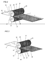
- the cylindrical surfaces 25 of the embossing rollers 16 and 17 will present areas 27 devoid of the aforementioned frustopyramidal projections 26 and reproducing the word "PULL" (or a selected graphic symbol having the same significance).
- the strip 4 passes through an arc substantially of 180° around the cylindrical surface 28 of the decoiling roller 21, which is furnished with a plurality of holes 29 connected to a source of negative pressure (not illustrated), thence around the idle diverter roller 22 and toward the cutter means 6.
- the circumference of the decoiling roller 21 is marginally greater than the circumference of the embossing rollers 16 and 17.
- the strip 4 undergoes a plastic deformation such that, with each cycle completed by the two rollers 16 and 17, the length of the embossed portion of strip emerging from the assembly 15 is dissimilar (generally less, but sometimes greater) to that of the unembossed portion entering the assembly.
- This variance or error can vary unpredictably over time, dependent as it is on a multiplicity of factors, for example ambient temperature and humidity, the quality of the material used for the strip 4, the degree of slippage between the strip 4 and the rollers 16 and 17 induced at the embossing station 24, and the tensile force to which the strip 4 is subject.
- the decoiling roller 21 rotates at a tangential velocity marginally greater than that of the embossing rollers 16 and 17, due to its greater circumference, and that the embossed strip 4 clings to the cylindrical surface 28 without slipping, the advancing strip 4 will be subjected, along the stretch between the embossing station 24 and the cylindrical surface 28, to a tensile force by which it is deformed plastically in a direction opposite to the force applied by the embossing rollers 16 and 17, but in a perfectly controlled manner.
- the random deformations induced by the embossing step are cancelled out and, where the circumference of the decoiling roller 21 happens to coincide with the predetermined length L mentioned above, the portions of embossed strip 4 fed cyclically to the cutter means 6, and ultimately the leaves 7 separated with each cycle of the selfsame cutter means 6, will be of length that remains constant over time and equal to the predetermined length L (see figure 2).
- the tension means 20 provide means (also denoted 20) by which to stabilize the length of the portions of embossed strip directed cyclically from the embossing assembly 15 to the cutter means 6.
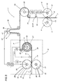
- Figure 4 illustrates an embodiment of the unit differing from that described above in that the decoiling roller 21 is driven by an independent variable speed motor 30, of which the operation is interlocked to a control circuit block denoted 31.
- strip 4 of wrapping material happens to be a preprinted type, for example procured from a paper mill and bearing printed images or logos, errors may occur in the positioning of the "PULL" mark relative to the images or logos.
- Such positioning errors could be occasioned by the aforementioned microslippages induced at the embossing station 24, and/or by irregular spacing between the preprinted images, and/or by the elasticity of the material used for the strip 4.
- a first input of the control circuit block 31 can be connected to means 32 capable of sensing the position of the images and/or the logo, typically a TV camera 33, and a second input to means 47 that will emit a cyclical timing signal referenced to the embossing roller 16.
- the position of the preprinted images and/or logos relative to the "PULL" mark impressed by the embossing rollers 16 and 17 can be correctly adjusted and maintained steady over time.
- the independent drive system also serves, in conjunction with the facility of controlling the tangential velocity of the decoiling roller 21 and with the feedback from the sensing means 32, to give exact and continuous control over the position of the "PULL" mark on each length of strip corresponding ultimately to a single leaf 7.
- the circumferential dimensions of the decoiling roller 21 are not critical in determining the length L of the leaf 7.
- the embodiment of figure 5 differs from that of figure 1 in that the infeed portion 1 is equipped further with a feed unit 35, interposed between the tension means 20 and the cutter means 6, comprising a first roller 35' power driven by a variable speed independent motor 36, and an idle roller 37 by which the strip 4 is diverted directly into the cutter means 6.
- a feed unit 35 interposed between the tension means 20 and the cutter means 6, comprising a first roller 35' power driven by a variable speed independent motor 36, and an idle roller 37 by which the strip 4 is diverted directly into the cutter means 6.
- variable speed roller 35' Whilst the decoiling roller 21 serves to stabilize the length of the portions of embossed strip directed cyclically along the feed path P, as in the examples already illustrated, the function of the variable speed roller 35' is to combine with the means illustrated in figure 4 (control circuit block 31, sensing means 32 and signal emitter means 34) in maintaining correct synchronization between the position of the "PULL" mark and the stroke of the cutter means 6.
- the strip 4 Passing from the decoiling roller 21 to the feed unit 35, the strip 4 is directed through a storage buffer 38 of the type comprising a negatively pressurized chamber 39 internally of which the running strip 4 forms a loop of variable length.
- buffer 38 which itself is of familiar embodiment, facilitates the adjustment and control operations described above by ensuring the strip 4 will run neither tight nor slack.
- the buffer 38 is equipped with relative sensing means 32', typically a photocell 41', such as will detect the level of the strip 4 internally of the chamber 39.
- the sensing means 32' are connected on the output side to a relative control circuit block 31, to which the motor 23 driving the embossing roller 16 and the decoiling roller 21 is also interlocked.
- the operation of the motor 23 can be piloted by the embossing unit 8 in response to signals received from the photocell 41', in such a way as will maintain the loop of strip 4 at a constant and predetermined level internally of the buffer 38.
- the unit according to the invention can include a control circuit block 31 as in the example of figure 4, of which a first input is connected to a TV camera 33 capable of sensing the position of the images and/or logos on the strip 4, and a second input to means 47 that will emit a cyclical timing signal referenced to the embossing roller 17.
- the positioning of the images and/or logos preprinted on the strip 4 can be adjusted and held steady relative to the "PULL" mark impressed with the embossing rollers 16 and 17.
- the decoiling roller 21 can be equipped with an independent motor 30, rather than being driven by the same motor 23 as the embossing roller 16.
- the word "PULL" impressed by the embossing rollers might be replaced by a reference mark 40 in the guise of a preprinted stripe or dash, that is to say a mark made on the strip by a printing device at intervals corresponding to the length of the single leaves 7, before the strip itself is wound onto the roll 5.
- the sensing means 32 illustrated in the examples of figure 4 and 5 could take the form of photocells 41 instead of TV cameras 33.
- the embossing unit 8 forms part of equipment 42 by which the embossed strip 4 is rewound onto a roll 5'.
- tension means 20 serving to stabilize the strip 4 might consist in a pair of rollers 43 and 44 set in contrarotation substantially tangential one to the other, such as will decoil one length L of embossed strip with each cycle of rotation.
- the cylindrical surface 25 of at least one embossing roller 16 or 17 presents an area, for example rectangular or circular in shape, devoid of frustopyramidal projections 26 and functioning as a die 45.
- the sole function of the die 45 is to impress a succession of cyclical reference marks 46 on the strip 4 such as can be used to effect a positional adjustment, relative to the cutter means 6, more accurate than that obtainable using the "PULL" mark and more reliable than that obtainable using a strip 4 with preprinted marks 40.
- the reference marks 46 impressed on the leaves 7 in such a way as to remain invisible when the packet is opened, are detectable by means of the photocell 41.
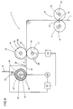
- the tension means 20 are located upstream of the embossing assembly 15.
- the aspirating decoil roller 21 is driven by an independent variable speed motor 30' interlocked in operation to a control circuit block 31'.
- a first input of the control circuit block 31' is connected to sensing means 32, located between the decoiling roller 21 and the embossing assembly 15 and consisting in a photocell 33 able to detect the position of preprinted marks 40 on the strip 4.
- a second input of the circuit block 31' is connected to means 34' such as will emit a cyclical timing signal referenced to the embossing roller 17.
- 48 denotes a diverting roller located downstream of the embossing assembly 15, by which the embossed strip 4 is directed toward the cutter means 6.
Landscapes
- Engineering & Computer Science (AREA)
- Mechanical Engineering (AREA)
- Machines For Manufacturing Corrugated Board In Mechanical Paper-Making Processes (AREA)
- Wrapping Of Specific Fragile Articles (AREA)
- Decoration Of Textiles (AREA)
- Packages (AREA)
- Shaping Of Tube Ends By Bending Or Straightening (AREA)
Abstract
Description
- The present invention relates to a unit for embossing a strip of wrapping material.
- In particular, the present invention relates to a unit serving to emboss a continuous strip of material, typically metal foil paper, that will be divided up ultimately into discrete lengths and fed to the wrapping mechanisms of a cigarette packer.
- In cigarette packers of conventional design, a strip of metal foil paper is drawn from a roll by decoiling means, directed along a predetermined feed path, taken up by cutting means and divided into single leaves each destined to envelop a group of cigarettes and thus provide an inner wrapper for a respective packet.
- At a given point upstream of the cutting means, likewise conventionally, the strip of material is subjected to the action of an embossing unit consisting in two rollers placed on opposite sides of the aforementioned feed path and contrarotating tangentially one relative to another.
- The two rollers are linked mechanically to the cutting means and present cylindrical surfaces with projections, generally of frustopyramidal shape, such as will indent the metallic strip passing between the rollers and cause it to assume the characteristic roughened texture adopted for inner foil wrappers.
- The cylindrical surface of each embossing roller, of which the circumferential measurement is equal substantially to the length of one leaf cut from the continuous strip, can present areas devoid of the aforementioned frustopyramidal projections, such as will combine to make up the letters of a word, "PULL", or a selected graphic symbol.
- Accordingly, the "PULL" mark (or selected graphic symbol) is created by leaving areas of the surface unembossed and will appear on each leaf of the cut strip, placed to coincide with a portion of the inner wrapper destined to be removed at the moment of opening the packet of cigarettes.
- Before the packer is set in motion, an operator adjusts the positioning of the strip relative to the cutting means, so that the "PULL" mark will be correctly located on each leaf and therefore on the inner wrapper of the finished packet.
- In practice, it has been found that the embossing step is a direct cause of certain drawbacks.
- More particularly, it has been observed that when subjected to the action of the embossing unit, which results in plastic deformation, the strip of wrapping material tends to behave in an entirely unpredictable manner due to a number of different factors: environmental (temperature and humidity), physical (quality of the material), and mechanical (in particular, the tension to which the strip is subject when passing through the embossing unit).
- As a consequence of the plastic deformation in question, which is also the cause of microslippage induced in the strip relative to the embossing rollers, and the above noted fact that the cutting means are linked mechanically to the embossing unit, the length of the leaves separated from the strip becomes irregular and will in general differ randomly from the correct value.
- This variation in length also results in a loss of timing, with the "PULL" mark shifting from its correct position on the leaf and therefore on the inner wrapper of the finished packet.
- The object of the present invention is to provide a unit for embossing a strip of wrapping material, from which the drawbacks mentioned above will be absent.
- The stated object is realized in a unit according to the present invention for embossing a strip of wrapping material, of which the features are as recited in one or more of the appended claims.
- The invention will now be described in detail, by way of example, with the aid of the accompanying drawings, in which:
- figure 1 illustrates an infeed portion of a cigarette packer, equipped with an embossing unit according to the present invention, viewed schematically and frontally in elevation and shown in a first embodiment,;
- figures 2 and 3 show a detail of figure 1, viewed in perspective;
- figures 4, 5 and 6 show three further embodiments of the unit according to the present invention, viewed schematically and frontally in elevation;
- figure 7 illustrates equipment for rewinding a strip of wrapping material, viewed frontally in elevation and equipped with an embossing unit according to the present invention.
- With reference to figure 1, numeral 1 denotes the infeed portion, in its entirety, of a cigarette packer incorporating a frame of which a
frontal bulkhead 2 is illustrated. - The infeed portion 1 comprises means, mounted to the
bulkhead 2 and illustrated schematically as a block, denoted 3, serving to guide and feed acontinuous strip 4 ofmetal foil paper 4 decoiled from aroll 5, also cutter means 6 by which thestrip 4 is divided intosingle leaves 7 destined to provide inner wrappers, fashioned through the agency of wrapping means (not illustrated), for cigarette packets. - Interposed between the guide and feed means 3 and the cutter means 6 is an embossing unit, denoted 8 in its entirety, mounted to a substantially rectangular
vertical plate 8a carried by thebulkhead 2. - The
embossing unit 8 combines with the guide and feed means 3 and the cutter means 6 to establish a feed path P along which thestrip 4 advances in the direction indicated by the arrow denoted F. - The cutter means 6 comprise two
contrarotating rollers horizontal axes blade 13 and with ananvil 14. - The
embossing unit 8 comprises anembossing assembly 15 that consists of twocontrarotating rollers respective axes axes strip 4 is deformed plastically in the longitudinal direction, or stretched, composed of a decoilingroller 21 turning clockwise on anaxis 21' parallel to theaxes idle diverter roller 22 located below the decoilingroller 21. - The
blade roller 9 of the cutter means 6 is coupled directly to theanvil roller 10 and driven by a motor indicated schematically as ablock 23. - Similarly, one embossing
roller 17 is coupled directly to theother embossing roller 16 and driven by theaforementioned motor 23, which also drives the decoilingroller 21. - With each single operating cycle of the
embossing unit 8, which corresponds to one full rotation of thecutter rollers blade 13 and theanvil 14 strike together on the line of the feed path P and separate aleaf 7 of predetermined length L from thestrip 4, destined to form the inner wrapper of a packet of cigarettes. - The two
embossing rollers leaf 7, or to a multiple thereof, and positioned mutually tangential at anembossing station 24; bothrollers cylindrical surfaces 25 covered byfrustopyramidal projections 26 such as will impress thestrip 4 with the familiar rough or reeded texture of an inner foil wrapper as it passes through theembossing station 24. - As illustrated in figure 2, the
cylindrical surfaces 25 of theembossing rollers areas 27 devoid of the aforementionedfrustopyramidal projections 26 and reproducing the word "PULL" (or a selected graphic symbol having the same significance). - Accordingly, this same mark, created by virtue of the area remaining unembossed, will appear on each of the
leaves 7 and therefore on the inner wrapper of each packet of cigarettes, positioned so as to be visible on opening the packet. - Once beyond the
embossing rollers strip 4 passes through an arc substantially of 180° around thecylindrical surface 28 of the decoilingroller 21, which is furnished with a plurality ofholes 29 connected to a source of negative pressure (not illustrated), thence around theidle diverter roller 22 and toward the cutter means 6. - The circumference of the decoiling
roller 21 is marginally greater than the circumference of theembossing rollers - Passing through the
embossing station 24, thestrip 4 undergoes a plastic deformation such that, with each cycle completed by the tworollers assembly 15 is dissimilar (generally less, but sometimes greater) to that of the unembossed portion entering the assembly. - This variance or error can vary unpredictably over time, dependent as it is on a multiplicity of factors, for example ambient temperature and humidity, the quality of the material used for the
strip 4, the degree of slippage between thestrip 4 and therollers embossing station 24, and the tensile force to which thestrip 4 is subject. - Given that the decoiling
roller 21 rotates at a tangential velocity marginally greater than that of theembossing rollers strip 4 clings to thecylindrical surface 28 without slipping, the advancingstrip 4 will be subjected, along the stretch between theembossing station 24 and thecylindrical surface 28, to a tensile force by which it is deformed plastically in a direction opposite to the force applied by theembossing rollers - Accordingly, the random deformations induced by the embossing step are cancelled out and, where the circumference of the decoiling
roller 21 happens to coincide with the predetermined length L mentioned above, the portions of embossedstrip 4 fed cyclically to the cutter means 6, and ultimately theleaves 7 separated with each cycle of the selfsame cutter means 6, will be of length that remains constant over time and equal to the predetermined length L (see figure 2). - Thus, the tension means 20 provide means (also denoted 20) by which to stabilize the length of the portions of embossed strip directed cyclically from the
embossing assembly 15 to the cutter means 6. - Figure 4 illustrates an embodiment of the unit differing from that described above in that the decoiling
roller 21 is driven by an independentvariable speed motor 30, of which the operation is interlocked to a control circuit block denoted 31. - Where the
strip 4 of wrapping material happens to be a preprinted type, for example procured from a paper mill and bearing printed images or logos, errors may occur in the positioning of the "PULL" mark relative to the images or logos. - Such positioning errors could be occasioned by the aforementioned microslippages induced at the
embossing station 24, and/or by irregular spacing between the preprinted images, and/or by the elasticity of the material used for thestrip 4. - In this instance, observing figure 4, a first input of the
control circuit block 31 can be connected to means 32 capable of sensing the position of the images and/or the logo, typically aTV camera 33, and a second input to means 47 that will emit a cyclical timing signal referenced to theembossing roller 16. - Thus, by controlling the speed of the decoiling
roller 21, the position of the preprinted images and/or logos relative to the "PULL" mark impressed by theembossing rollers - In addition, it will be seen that the independent drive system also serves, in conjunction with the facility of controlling the tangential velocity of the decoiling
roller 21 and with the feedback from the sensing means 32, to give exact and continuous control over the position of the "PULL" mark on each length of strip corresponding ultimately to asingle leaf 7. In this instance, clearly enough, the circumferential dimensions of the decoilingroller 21 are not critical in determining the length L of theleaf 7. - The embodiment of figure 5 differs from that of figure 1 in that the infeed portion 1 is equipped further with a
feed unit 35, interposed between the tension means 20 and the cutter means 6, comprising a first roller 35' power driven by a variable speedindependent motor 36, and anidle roller 37 by which thestrip 4 is diverted directly into the cutter means 6. - Whilst the decoiling
roller 21 serves to stabilize the length of the portions of embossed strip directed cyclically along the feed path P, as in the examples already illustrated, the function of the variable speed roller 35' is to combine with the means illustrated in figure 4 (control circuit block 31, sensing means 32 and signal emitter means 34) in maintaining correct synchronization between the position of the "PULL" mark and the stroke of the cutter means 6. - Passing from the decoiling
roller 21 to thefeed unit 35, thestrip 4 is directed through astorage buffer 38 of the type comprising a negatively pressurizedchamber 39 internally of which therunning strip 4 forms a loop of variable length. - The inclusion of the
buffer 38, which itself is of familiar embodiment, facilitates the adjustment and control operations described above by ensuring thestrip 4 will run neither tight nor slack. - With this precise end in view, the
buffer 38 is equipped with relative sensing means 32', typically a photocell 41', such as will detect the level of thestrip 4 internally of thechamber 39. - The sensing means 32' are connected on the output side to a relative
control circuit block 31, to which themotor 23 driving theembossing roller 16 and the decoilingroller 21 is also interlocked. - In this situation, the operation of the
motor 23 can be piloted by theembossing unit 8 in response to signals received from the photocell 41', in such a way as will maintain the loop ofstrip 4 at a constant and predetermined level internally of thebuffer 38. - Likewise in this embodiment, the unit according to the invention can include a
control circuit block 31 as in the example of figure 4, of which a first input is connected to aTV camera 33 capable of sensing the position of the images and/or logos on thestrip 4, and a second input to means 47 that will emit a cyclical timing signal referenced to theembossing roller 17. - Accordingly, and in like manner to the example of figure 4, by controlling the speed of the decoiling
roller 21, the positioning of the images and/or logos preprinted on thestrip 4 can be adjusted and held steady relative to the "PULL" mark impressed with theembossing rollers - Finally, it will be appreciated that in the example of figure 5, the decoiling
roller 21 can be equipped with anindependent motor 30, rather than being driven by thesame motor 23 as theembossing roller 16. - Referring again to figure 2, it will be seen that the word "PULL" impressed by the embossing rollers might be replaced by a
reference mark 40 in the guise of a preprinted stripe or dash, that is to say a mark made on the strip by a printing device at intervals corresponding to the length of thesingle leaves 7, before the strip itself is wound onto theroll 5. - Where printed
reference marks 40 are used, the sensing means 32 illustrated in the examples of figure 4 and 5 could take the form ofphotocells 41 instead ofTV cameras 33. - In the example of figure 7, the
embossing unit 8 forms part ofequipment 42 by which the embossedstrip 4 is rewound onto a roll 5'. - Instead of the aspirating
roller 21, tension means 20 serving to stabilize thestrip 4 might consist in a pair ofrollers - In a further embodiment of the unit, illustrated in figure 3, the
cylindrical surface 25 of at least oneembossing roller 16 or 17 (that denoted 16 in figure 3) presents an area, for example rectangular or circular in shape, devoid offrustopyramidal projections 26 and functioning as adie 45. - The sole function of the
die 45 is to impress a succession ofcyclical reference marks 46 on thestrip 4 such as can be used to effect a positional adjustment, relative to the cutter means 6, more accurate than that obtainable using the "PULL" mark and more reliable than that obtainable using astrip 4 withpreprinted marks 40. - The
reference marks 46, impressed on theleaves 7 in such a way as to remain invisible when the packet is opened, are detectable by means of thephotocell 41. - In the example of figure 6, the tension means 20 are located upstream of the
embossing assembly 15. The aspiratingdecoil roller 21 is driven by an independent variable speed motor 30' interlocked in operation to a control circuit block 31'. - A first input of the control circuit block 31' is connected to
sensing means 32, located between the decoilingroller 21 and theembossing assembly 15 and consisting in aphotocell 33 able to detect the position of preprintedmarks 40 on thestrip 4. A second input of the circuit block 31' is connected to means 34' such as will emit a cyclical timing signal referenced to theembossing roller 17. - With this arrangement, it becomes possible to control the positioning of the preprinted marks 40 relative to the
embossing rollers - Finally, 48 denotes a diverting roller located downstream of the embossing
assembly 15, by which the embossedstrip 4 is directed toward the cutter means 6.
Claims (21)
- A unit for embossing a strip of wrapping material separable into leaves (7) for use by the wrapping equipment of a packer machine, comprising a pair of embossing rollers (16, 17) positioned along a predetermined feed path (P) followed by the strip (4) and establishing an embossing station (24),
characterized
in that it comprises means (20), positioned along the feed path (P), by which the strip is deformed plastically or stretched. - An embossing unit as in claim 1, wherein plastic deformation means (20) consist in means (20) by which to stabilize the length measurement presented by portions of embossed strip (4) constituting the leaves (7).
- An embossing unit as in claim 2, wherein the stabilizing means (20) are located downstream of the embossing station (24).
- An embossing unit as in claims 1 to 3, wherein stabilizing means (20) comprise rotary decoiling means (21) by which a portion of the strip (4) presenting a predetermined length (L) is advanced with each operating cycle.
- An embossing unit as in claim 4, wherein decoiling means (20) comprise an aspirating decoil roller (21) such as will prevent slippage between the strip (4) and the cylindrical surface (28) of the selfsame roller (21).
- An embossing unit as in claim 4, wherein decoiling means (21) comprise two contrarotating rollers (43, 44) substantially tangential one to another.
- An embossing unit as in claims 4 to 6, wherein the decoiling means (21) rotate at a tangential velocity marginally greater than that of the embossing rollers (16, 17), in such a way that the strip (4) is subjected to a tensile force along the portion of the feed path (P) extending between the embossing station (24) and the selfsame decoiling means (21).
- An embossing unit as in claims 1 to 7, wherein the decoiling rollers (21; 43, 44) are set in motion by variable speed drive means (30) interlocked in operation to means (32) capable of sensing images and/or logos printed previously on the strip (4).
- An embossing unit as in claims 1 to 8, comprising a variable speed feed unit (35) installed downstream of the decoiling means (21), interlocked in operation to means (32) capable of sensing reference marks located on the strip (4) at intervals of predetermined length (L).
- An embossing unit as in claim 8 or 9, wherein the reference marks consist in lettering (PULL) or an equivalent graphic symbol identifying a removable portion of each leaf (7), and sensing means (32) consist in a TV camera (33).
- An embossing unit as in claim 8 or 9, wherein the reference marks consist in stripes or dashes (40) printed previously on the strip (4).
- An embossing unit as in claim 8 or 9, wherein the reference marks consist in impressions (45) made on the strip (4) by the embossing rollers (16, 17).
- An embossing unit as in claim 11 or 12, wherein sensing means (32) consist in a photocell (41).
- An embossing unit as in claim 9, comprising a storage buffer (38) occupiable by the advancing strip (4), located along the portion of the feed path (P) interposed between the decoiling means (20) and the feed unit (35).
- An embossing unit as in claim 14, further comprising means (32') associated with the storage buffer (38) and serving to monitor the level of the strip (4) internally of the buffer (38), such as will supply an output signal to a relative control circuit block (31) piloting the operation of the motor (23) driving the embossing assembly (15) and the decoiling roller (21).
- An embossing unit as in claim 2 or claims 4 to 6, wherein the stabilizing means (20), provided by the decoiling roller (21), are positioned upstream of the embossing station (24).
- An embossing unit as in claim 16, wherein the decoiling roller (21) is set in rotation by variable speed drive means (30') interlocked in operation to means (32) capable of sensing preprinted reference marks (40) on the strip (4).
- A cigarette packer, equipped with an embossing unit (8) as in the preceding claims.
- Equipment for rewinding an embossed strip (4) onto a roll, comprising an embossing unit (8) as in one or more of the preceding claims.
- A unit for embossing a strip of wrapping material separable into leaves (7) for use by the wrapping equipment of a packer machine, comprising a pair of embossing rollers (16, 17) positioned along a predetermined feed path (P) followed by the strip (4) and establishing an embossing station (24), wherein the cylindrical surface of at least one of the two embossing rollers (16, 17) comprises at least one die (45) such as will impress reference marks (46) cyclically on the strip (4).
- Embossed strip, characterized in that it is obtained by means of an embossing unit embodied as in any one of claims 1 to 20.
Applications Claiming Priority (1)
| Application Number | Priority Date | Filing Date | Title |
|---|---|---|---|
| IT000114A ITBO20050114A1 (en) | 2005-03-02 | 2005-03-02 | EMBOSSING UNIT OF A WRAPPING MATERIAL TAPE |
Publications (2)
| Publication Number | Publication Date |
|---|---|
| EP1698450A1 true EP1698450A1 (en) | 2006-09-06 |
| EP1698450B1 EP1698450B1 (en) | 2009-09-02 |
Family
ID=34956663
Family Applications (1)
| Application Number | Title | Priority Date | Filing Date |
|---|---|---|---|
| EP06110526A Expired - Lifetime EP1698450B1 (en) | 2005-03-02 | 2006-02-28 | A unit for embossing a strip of wrapping material |
Country Status (7)
| Country | Link |
|---|---|
| US (1) | US20060198920A1 (en) |
| EP (1) | EP1698450B1 (en) |
| JP (1) | JP4979961B2 (en) |
| CN (1) | CN1827369A (en) |
| AT (1) | ATE441518T1 (en) |
| DE (1) | DE602006008842D1 (en) |
| IT (1) | ITBO20050114A1 (en) |
Cited By (7)
| Publication number | Priority date | Publication date | Assignee | Title |
|---|---|---|---|---|
| EP1954568A1 (en) | 2005-11-25 | 2008-08-13 | Focke & Co. (GmbH & Co. KG) | Method of, and apparatus for, producing blanks for an inner wrapper of a cigarette group |
| WO2009141217A1 (en) | 2008-05-20 | 2009-11-26 | British American Tobacco (Investments) Limited | Apparatus and method for making a smoking article |
| WO2011042354A1 (en) * | 2009-10-06 | 2011-04-14 | British American Tobacco (Investments) Limited | Printed and embossed wrapper for a smoking article and smoking article including a printed and embossed wrapper |
| DE102012104060A1 (en) * | 2012-05-09 | 2013-11-14 | Focke & Co. (Gmbh & Co. Kg) | Method and device for producing blanks, in particular for packs for cigarettes |
| DE102013008250A1 (en) * | 2013-05-15 | 2014-11-20 | Focke & Co. (Gmbh & Co. Kg) | Method and device for producing packaging for tobacco products |
| WO2014206511A1 (en) * | 2013-06-24 | 2014-12-31 | Focke & Co. (GmbH Co. KG) | Method and apparatus for producing blanks for an inner wrapper of a cigarette group |
| EP2668009B1 (en) | 2011-01-26 | 2016-03-30 | GIMA TT S.p.A. | Apparatus and method to make blanks |
Families Citing this family (8)
| Publication number | Priority date | Publication date | Assignee | Title |
|---|---|---|---|---|
| DE102007053806A1 (en) * | 2007-11-12 | 2009-05-14 | Heidelberger Druckmaschinen Ag | Rotary embosser |
| AT509189A1 (en) * | 2009-11-17 | 2011-06-15 | Tannpapier Gmbh | METHOD FOR CREATING A MOUTHPIECE OF A CIGARETTE MOUTHPIECE |
| DE102012019372B4 (en) * | 2011-10-26 | 2025-03-13 | Masterwork Machinery Co., Ltd. | Method for embossing products with a rotary embossing device |
| JP6010962B2 (en) * | 2012-03-27 | 2016-10-19 | 王子ホールディングス株式会社 | Manufacturing method of sanitary paper |
| EP3230055A1 (en) * | 2014-12-04 | 2017-10-18 | Bobst Mex Sa | Method and work station for the conversion of a flat support |
| JP2021003806A (en) * | 2018-01-29 | 2021-01-14 | スリーエム イノベイティブ プロパティズ カンパニー | Printing method on filamentous member, and filamentous saw |
| CN110315804A (en) * | 2019-07-29 | 2019-10-11 | 义乌市珂莉科技有限公司 | A kind of washing paper automatic embossing die-cutting machine |
| CN115014167A (en) * | 2022-06-09 | 2022-09-06 | 嘉兴慕思寝室用品有限公司 | Size identification control device and method for flexible material |
Citations (3)
| Publication number | Priority date | Publication date | Assignee | Title |
|---|---|---|---|---|
| DE4342737A1 (en) * | 1993-12-15 | 1995-06-22 | Topack Verpacktech Gmbh | Method and device for producing embossed film blanks |
| EP0839719A1 (en) * | 1996-10-31 | 1998-05-06 | Focke & Co. (GmbH & Co.) | Device for making packages using thin packaging material |
| JPH11245924A (en) * | 1998-03-03 | 1999-09-14 | Japan Tobacco Inc | Embossing apparatus of cigarette packaging machine |
Family Cites Families (8)
| Publication number | Priority date | Publication date | Assignee | Title |
|---|---|---|---|---|
| JPH089159B2 (en) * | 1993-04-28 | 1996-01-31 | 收 三宅 | Method and device for separating punched sheet |
| JPH09118315A (en) * | 1995-10-20 | 1997-05-06 | Ckd Corp | Film mark alignment device for molding, filling and packaging machines |
| US6258308B1 (en) * | 1996-07-31 | 2001-07-10 | Exxon Chemical Patents Inc. | Process for adjusting WVTR and other properties of a polyolefin film |
| JPH10245012A (en) * | 1997-03-03 | 1998-09-14 | Ishida Co Ltd | Web transport speed control device |
| US6193918B1 (en) * | 1999-04-09 | 2001-02-27 | The Procter & Gamble Company | High speed embossing and adhesive printing process and apparatus |
| DE10143420C2 (en) * | 2001-09-05 | 2003-10-09 | Reifenhaeuser Masch | Method and device for producing a breathable material web |
| AR038590A1 (en) * | 2002-02-22 | 2005-01-19 | Clopay Plastic Prod Co | LAMINATED FILM SHEET AND METHODS FOR MANUFACTURING |
| ITBO20040519A1 (en) * | 2004-08-09 | 2004-11-09 | Gd Spa | EMBOSSING UNIT |
-
2005
- 2005-03-02 IT IT000114A patent/ITBO20050114A1/en unknown
-
2006
- 2006-02-28 JP JP2006053623A patent/JP4979961B2/en not_active Expired - Fee Related
- 2006-02-28 AT AT06110526T patent/ATE441518T1/en not_active IP Right Cessation
- 2006-02-28 EP EP06110526A patent/EP1698450B1/en not_active Expired - Lifetime
- 2006-02-28 DE DE602006008842T patent/DE602006008842D1/en not_active Expired - Lifetime
- 2006-03-01 CN CN200610058841.3A patent/CN1827369A/en active Pending
- 2006-03-01 US US11/364,441 patent/US20060198920A1/en not_active Abandoned
Patent Citations (3)
| Publication number | Priority date | Publication date | Assignee | Title |
|---|---|---|---|---|
| DE4342737A1 (en) * | 1993-12-15 | 1995-06-22 | Topack Verpacktech Gmbh | Method and device for producing embossed film blanks |
| EP0839719A1 (en) * | 1996-10-31 | 1998-05-06 | Focke & Co. (GmbH & Co.) | Device for making packages using thin packaging material |
| JPH11245924A (en) * | 1998-03-03 | 1999-09-14 | Japan Tobacco Inc | Embossing apparatus of cigarette packaging machine |
Non-Patent Citations (1)
| Title |
|---|
| PATENT ABSTRACTS OF JAPAN vol. 1999, no. 14 22 December 1999 (1999-12-22) * |
Cited By (17)
| Publication number | Priority date | Publication date | Assignee | Title |
|---|---|---|---|---|
| EP1954568A1 (en) | 2005-11-25 | 2008-08-13 | Focke & Co. (GmbH & Co. KG) | Method of, and apparatus for, producing blanks for an inner wrapper of a cigarette group |
| CN102098932B (en) * | 2008-05-20 | 2015-11-25 | 英美烟草(投资)有限公司 | Apparatus and method for making smoking articles |
| WO2009141217A1 (en) | 2008-05-20 | 2009-11-26 | British American Tobacco (Investments) Limited | Apparatus and method for making a smoking article |
| CN102098932A (en) * | 2008-05-20 | 2011-06-15 | 英美烟草(投资)有限公司 | Apparatus and method for making smoking articles |
| EP2486811A1 (en) * | 2008-05-20 | 2012-08-15 | British American Tobacco (Investments) Limited | Apparatus and method for making a smoking article |
| US10231478B2 (en) | 2008-05-20 | 2019-03-19 | British American Tobacco (Investments) Limited | Apparatus and method for making a smoking article |
| US10264814B2 (en) | 2008-05-20 | 2019-04-23 | British American Tobacco (Investments) Limited | Apparatus and method for making a smoking article |
| WO2011042354A1 (en) * | 2009-10-06 | 2011-04-14 | British American Tobacco (Investments) Limited | Printed and embossed wrapper for a smoking article and smoking article including a printed and embossed wrapper |
| EP2668009B1 (en) | 2011-01-26 | 2016-03-30 | GIMA TT S.p.A. | Apparatus and method to make blanks |
| WO2013167269A1 (en) * | 2012-05-09 | 2013-11-14 | Focke & Co. (Gmbh & Co. Kg) | Method and device for producing blanks, in particular for packages for cigarettes |
| CN104411589A (en) * | 2012-05-09 | 2015-03-11 | 佛克有限及两合公司 | Method and device for producing blanks, in particular for packages for cigarettes |
| CN104411589B (en) * | 2012-05-09 | 2016-03-16 | 佛克有限及两合公司 | For the manufacture of the method and apparatus of the cut piece in particular for cigarette packages |
| DE102012104060A1 (en) * | 2012-05-09 | 2013-11-14 | Focke & Co. (Gmbh & Co. Kg) | Method and device for producing blanks, in particular for packs for cigarettes |
| WO2014183830A3 (en) * | 2013-05-15 | 2014-12-31 | Focke & Co. (Gmbh & Co. Kg) | Method and device for making packages for tobacco products |
| DE102013008250A1 (en) * | 2013-05-15 | 2014-11-20 | Focke & Co. (Gmbh & Co. Kg) | Method and device for producing packaging for tobacco products |
| WO2014206511A1 (en) * | 2013-06-24 | 2014-12-31 | Focke & Co. (GmbH Co. KG) | Method and apparatus for producing blanks for an inner wrapper of a cigarette group |
| CN105408210A (en) * | 2013-06-24 | 2016-03-16 | 佛克有限及两合公司 | Method and apparatus for manufacturing blanks for inner packaging parts of groups of cigarettes |
Also Published As
| Publication number | Publication date |
|---|---|
| CN1827369A (en) | 2006-09-06 |
| ATE441518T1 (en) | 2009-09-15 |
| US20060198920A1 (en) | 2006-09-07 |
| JP2006240742A (en) | 2006-09-14 |
| DE602006008842D1 (en) | 2009-10-15 |
| JP4979961B2 (en) | 2012-07-18 |
| ITBO20050114A1 (en) | 2005-06-01 |
| EP1698450B1 (en) | 2009-09-02 |
Similar Documents
| Publication | Publication Date | Title |
|---|---|---|
| EP1698450B1 (en) | A unit for embossing a strip of wrapping material | |
| RU2471629C2 (en) | Device and method of making embossed paper or laminated metallic foil | |
| EP0868998B1 (en) | High speed web machine | |
| EP0684129B1 (en) | Labels and manufacture thereof | |
| KR880002391B1 (en) | Method and apparatus for arrangement in the forward feeding of a material web in register with a crease lime pattern | |
| JPH11106121A (en) | Roll manufacturing method and rewinder | |
| US1905446A (en) | Film backing paper making machine | |
| AU2002325830A1 (en) | Printing unit wrapping strips of tobacco and a printing method | |
| JPH0592852A (en) | Frequency changing device, rewinding device, length changing method and number changing method | |
| US4421587A (en) | Label feeder for fan folded documents | |
| US20180297354A1 (en) | Methods and Apparatuses for producing a newspaper comprising aligning preprinted images to the operations of a press and modifying the cutoff length of the preprinted images | |
| RU2652578C2 (en) | Embossing device and a packaging unit containing this device | |
| GB2285414A (en) | Making embossed blanks of flexible sheet material | |
| RU2654449C2 (en) | Embossing device and packaging unit | |
| US20040173073A1 (en) | Pouch machine with a rotary die cutter | |
| US7437982B2 (en) | Unit for feeding and cutting into lengths a strip of wrapping material | |
| JPH0976460A (en) | Paper cutting device in folding device for form printing machine | |
| CN1191178C (en) | Method and device for producing a skinned package | |
| CN217102415U (en) | Zero meter device and puncher that puncher was used | |
| GB2375527A (en) | Synchronising a printed image on an embossed web | |
| US3252640A (en) | Web propelling cylinders for high speed web processing machines | |
| EP0513649A1 (en) | Method of producing at least one continuous stream of cigarettes | |
| CN114104830A (en) | Zero meter device and puncher that puncher was used | |
| JP2886678B2 (en) | Web collating method and collating device | |
| CN120418077A (en) | Printing device, printing method and material web |
Legal Events
| Date | Code | Title | Description |
|---|---|---|---|
| PUAI | Public reference made under article 153(3) epc to a published international application that has entered the european phase |
Free format text: ORIGINAL CODE: 0009012 |
|
| AK | Designated contracting states |
Kind code of ref document: A1 Designated state(s): AT BE BG CH CY CZ DE DK EE ES FI FR GB GR HU IE IS IT LI LT LU LV MC NL PL PT RO SE SI SK TR |
|
| AX | Request for extension of the european patent |
Extension state: AL BA HR MK YU |
|
| 17P | Request for examination filed |
Effective date: 20061030 |
|
| AKX | Designation fees paid |
Designated state(s): AT BE BG CH CY CZ DE DK EE ES FI FR GB GR HU IE IS IT LI LT LU LV MC NL PL PT RO SE SI SK TR |
|
| 17Q | First examination report despatched |
Effective date: 20070620 |
|
| GRAP | Despatch of communication of intention to grant a patent |
Free format text: ORIGINAL CODE: EPIDOSNIGR1 |
|
| GRAS | Grant fee paid |
Free format text: ORIGINAL CODE: EPIDOSNIGR3 |
|
| GRAA | (expected) grant |
Free format text: ORIGINAL CODE: 0009210 |
|
| AK | Designated contracting states |
Kind code of ref document: B1 Designated state(s): AT BE BG CH CY CZ DE DK EE ES FI FR GB GR HU IE IS IT LI LT LU LV MC NL PL PT RO SE SI SK TR |
|
| REG | Reference to a national code |
Ref country code: CH Ref legal event code: EP |
|
| REG | Reference to a national code |
Ref country code: IE Ref legal event code: FG4D |
|
| REF | Corresponds to: |
Ref document number: 602006008842 Country of ref document: DE Date of ref document: 20091015 Kind code of ref document: P |
|
| REG | Reference to a national code |
Ref country code: CH Ref legal event code: NV Representative=s name: BUGNION S.A. |
|
| PG25 | Lapsed in a contracting state [announced via postgrant information from national office to epo] |
Ref country code: SE Free format text: LAPSE BECAUSE OF FAILURE TO SUBMIT A TRANSLATION OF THE DESCRIPTION OR TO PAY THE FEE WITHIN THE PRESCRIBED TIME-LIMIT Effective date: 20090902 Ref country code: FI Free format text: LAPSE BECAUSE OF FAILURE TO SUBMIT A TRANSLATION OF THE DESCRIPTION OR TO PAY THE FEE WITHIN THE PRESCRIBED TIME-LIMIT Effective date: 20090902 Ref country code: LT Free format text: LAPSE BECAUSE OF FAILURE TO SUBMIT A TRANSLATION OF THE DESCRIPTION OR TO PAY THE FEE WITHIN THE PRESCRIBED TIME-LIMIT Effective date: 20090902 |
|
| NLV1 | Nl: lapsed or annulled due to failure to fulfill the requirements of art. 29p and 29m of the patents act | ||
| LTIE | Lt: invalidation of european patent or patent extension |
Effective date: 20090902 |
|
| PG25 | Lapsed in a contracting state [announced via postgrant information from national office to epo] |
Ref country code: PL Free format text: LAPSE BECAUSE OF FAILURE TO SUBMIT A TRANSLATION OF THE DESCRIPTION OR TO PAY THE FEE WITHIN THE PRESCRIBED TIME-LIMIT Effective date: 20090902 Ref country code: NL Free format text: LAPSE BECAUSE OF FAILURE TO SUBMIT A TRANSLATION OF THE DESCRIPTION OR TO PAY THE FEE WITHIN THE PRESCRIBED TIME-LIMIT Effective date: 20090902 Ref country code: LV Free format text: LAPSE BECAUSE OF FAILURE TO SUBMIT A TRANSLATION OF THE DESCRIPTION OR TO PAY THE FEE WITHIN THE PRESCRIBED TIME-LIMIT Effective date: 20090902 Ref country code: SI Free format text: LAPSE BECAUSE OF FAILURE TO SUBMIT A TRANSLATION OF THE DESCRIPTION OR TO PAY THE FEE WITHIN THE PRESCRIBED TIME-LIMIT Effective date: 20090902 |
|
| PG25 | Lapsed in a contracting state [announced via postgrant information from national office to epo] |
Ref country code: CY Free format text: LAPSE BECAUSE OF FAILURE TO SUBMIT A TRANSLATION OF THE DESCRIPTION OR TO PAY THE FEE WITHIN THE PRESCRIBED TIME-LIMIT Effective date: 20090902 |
|
| PG25 | Lapsed in a contracting state [announced via postgrant information from national office to epo] |
Ref country code: IS Free format text: LAPSE BECAUSE OF FAILURE TO SUBMIT A TRANSLATION OF THE DESCRIPTION OR TO PAY THE FEE WITHIN THE PRESCRIBED TIME-LIMIT Effective date: 20100102 Ref country code: RO Free format text: LAPSE BECAUSE OF FAILURE TO SUBMIT A TRANSLATION OF THE DESCRIPTION OR TO PAY THE FEE WITHIN THE PRESCRIBED TIME-LIMIT Effective date: 20090902 Ref country code: CZ Free format text: LAPSE BECAUSE OF FAILURE TO SUBMIT A TRANSLATION OF THE DESCRIPTION OR TO PAY THE FEE WITHIN THE PRESCRIBED TIME-LIMIT Effective date: 20090902 Ref country code: PT Free format text: LAPSE BECAUSE OF FAILURE TO SUBMIT A TRANSLATION OF THE DESCRIPTION OR TO PAY THE FEE WITHIN THE PRESCRIBED TIME-LIMIT Effective date: 20100104 Ref country code: ES Free format text: LAPSE BECAUSE OF FAILURE TO SUBMIT A TRANSLATION OF THE DESCRIPTION OR TO PAY THE FEE WITHIN THE PRESCRIBED TIME-LIMIT Effective date: 20091213 Ref country code: EE Free format text: LAPSE BECAUSE OF FAILURE TO SUBMIT A TRANSLATION OF THE DESCRIPTION OR TO PAY THE FEE WITHIN THE PRESCRIBED TIME-LIMIT Effective date: 20090902 |
|
| PG25 | Lapsed in a contracting state [announced via postgrant information from national office to epo] |
Ref country code: SK Free format text: LAPSE BECAUSE OF FAILURE TO SUBMIT A TRANSLATION OF THE DESCRIPTION OR TO PAY THE FEE WITHIN THE PRESCRIBED TIME-LIMIT Effective date: 20090902 |
|
| PG25 | Lapsed in a contracting state [announced via postgrant information from national office to epo] |
Ref country code: AT Free format text: LAPSE BECAUSE OF FAILURE TO SUBMIT A TRANSLATION OF THE DESCRIPTION OR TO PAY THE FEE WITHIN THE PRESCRIBED TIME-LIMIT Effective date: 20090902 Ref country code: BE Free format text: LAPSE BECAUSE OF FAILURE TO SUBMIT A TRANSLATION OF THE DESCRIPTION OR TO PAY THE FEE WITHIN THE PRESCRIBED TIME-LIMIT Effective date: 20090902 |
|
| PLBE | No opposition filed within time limit |
Free format text: ORIGINAL CODE: 0009261 |
|
| STAA | Information on the status of an ep patent application or granted ep patent |
Free format text: STATUS: NO OPPOSITION FILED WITHIN TIME LIMIT |
|
| PG25 | Lapsed in a contracting state [announced via postgrant information from national office to epo] |
Ref country code: DK Free format text: LAPSE BECAUSE OF FAILURE TO SUBMIT A TRANSLATION OF THE DESCRIPTION OR TO PAY THE FEE WITHIN THE PRESCRIBED TIME-LIMIT Effective date: 20090902 |
|
| 26N | No opposition filed |
Effective date: 20100603 |
|
| PG25 | Lapsed in a contracting state [announced via postgrant information from national office to epo] |
Ref country code: MC Free format text: LAPSE BECAUSE OF NON-PAYMENT OF DUE FEES Effective date: 20100301 Ref country code: GR Free format text: LAPSE BECAUSE OF FAILURE TO SUBMIT A TRANSLATION OF THE DESCRIPTION OR TO PAY THE FEE WITHIN THE PRESCRIBED TIME-LIMIT Effective date: 20091203 |
|
| REG | Reference to a national code |
Ref country code: FR Ref legal event code: ST Effective date: 20101029 |
|
| PG25 | Lapsed in a contracting state [announced via postgrant information from national office to epo] |
Ref country code: FR Free format text: LAPSE BECAUSE OF NON-PAYMENT OF DUE FEES Effective date: 20100301 Ref country code: IE Free format text: LAPSE BECAUSE OF NON-PAYMENT OF DUE FEES Effective date: 20100228 |
|
| PG25 | Lapsed in a contracting state [announced via postgrant information from national office to epo] |
Ref country code: IT Free format text: LAPSE BECAUSE OF FAILURE TO SUBMIT A TRANSLATION OF THE DESCRIPTION OR TO PAY THE FEE WITHIN THE PRESCRIBED TIME-LIMIT Effective date: 20090902 |
|
| PG25 | Lapsed in a contracting state [announced via postgrant information from national office to epo] |
Ref country code: HU Free format text: LAPSE BECAUSE OF FAILURE TO SUBMIT A TRANSLATION OF THE DESCRIPTION OR TO PAY THE FEE WITHIN THE PRESCRIBED TIME-LIMIT Effective date: 20100303 Ref country code: LU Free format text: LAPSE BECAUSE OF NON-PAYMENT OF DUE FEES Effective date: 20100228 |
|
| PG25 | Lapsed in a contracting state [announced via postgrant information from national office to epo] |
Ref country code: TR Free format text: LAPSE BECAUSE OF FAILURE TO SUBMIT A TRANSLATION OF THE DESCRIPTION OR TO PAY THE FEE WITHIN THE PRESCRIBED TIME-LIMIT Effective date: 20090902 |
|
| PG25 | Lapsed in a contracting state [announced via postgrant information from national office to epo] |
Ref country code: BG Free format text: LAPSE BECAUSE OF NON-PAYMENT OF DUE FEES Effective date: 20090902 |
|
| PGFP | Annual fee paid to national office [announced via postgrant information from national office to epo] |
Ref country code: GB Payment date: 20150226 Year of fee payment: 10 |
|
| GBPC | Gb: european patent ceased through non-payment of renewal fee |
Effective date: 20160228 |
|
| PG25 | Lapsed in a contracting state [announced via postgrant information from national office to epo] |
Ref country code: GB Free format text: LAPSE BECAUSE OF NON-PAYMENT OF DUE FEES Effective date: 20160228 |
|
| P01 | Opt-out of the competence of the unified patent court (upc) registered |
Effective date: 20230526 |
|
| PGFP | Annual fee paid to national office [announced via postgrant information from national office to epo] |
Ref country code: DE Payment date: 20250227 Year of fee payment: 20 |
|
| PGFP | Annual fee paid to national office [announced via postgrant information from national office to epo] |
Ref country code: CH Payment date: 20250304 Year of fee payment: 20 |
|
| REG | Reference to a national code |
Ref country code: CH Ref legal event code: H14 Free format text: ST27 STATUS EVENT CODE: U-0-0-H10-H14 (AS PROVIDED BY THE NATIONAL OFFICE) Effective date: 20260228 Ref country code: DE Ref legal event code: R071 Ref document number: 602006008842 Country of ref document: DE |