EP1697065B1 - Improvements in screen separators - Google Patents
Improvements in screen separators Download PDFInfo
- Publication number
- EP1697065B1 EP1697065B1 EP04798533A EP04798533A EP1697065B1 EP 1697065 B1 EP1697065 B1 EP 1697065B1 EP 04798533 A EP04798533 A EP 04798533A EP 04798533 A EP04798533 A EP 04798533A EP 1697065 B1 EP1697065 B1 EP 1697065B1
- Authority
- EP
- European Patent Office
- Prior art keywords
- chassis
- sheath
- cover
- screen
- separator
- Prior art date
- Legal status (The legal status is an assumption and is not a legal conclusion. Google has not performed a legal analysis and makes no representation as to the accuracy of the status listed.)
- Expired - Lifetime
Links
- 230000006872 improvement Effects 0.000 title description 2
- 239000000463 material Substances 0.000 claims abstract description 19
- 238000010276 construction Methods 0.000 claims description 24
- 230000008878 coupling Effects 0.000 claims description 6
- 238000010168 coupling process Methods 0.000 claims description 6
- 238000005859 coupling reaction Methods 0.000 claims description 6
- 230000002093 peripheral effect Effects 0.000 claims description 6
- 230000000694 effects Effects 0.000 claims description 5
- 238000007873 sieving Methods 0.000 abstract description 3
- 230000002265 prevention Effects 0.000 description 8
- 238000012986 modification Methods 0.000 description 7
- 230000004048 modification Effects 0.000 description 7
- 239000000523 sample Substances 0.000 description 6
- 238000007789 sealing Methods 0.000 description 6
- 238000013461 design Methods 0.000 description 5
- 125000006850 spacer group Chemical group 0.000 description 4
- 238000004140 cleaning Methods 0.000 description 3
- 238000001514 detection method Methods 0.000 description 3
- 239000002245 particle Substances 0.000 description 3
- 239000003570 air Substances 0.000 description 2
- 230000008859 change Effects 0.000 description 2
- 239000000356 contaminant Substances 0.000 description 2
- 238000011109 contamination Methods 0.000 description 2
- 238000011065 in-situ storage Methods 0.000 description 2
- 238000012423 maintenance Methods 0.000 description 2
- 239000012858 resilient material Substances 0.000 description 2
- 238000000926 separation method Methods 0.000 description 2
- 239000007858 starting material Substances 0.000 description 2
- 239000004743 Polypropylene Substances 0.000 description 1
- 229910000831 Steel Inorganic materials 0.000 description 1
- 230000009471 action Effects 0.000 description 1
- 239000012080 ambient air Substances 0.000 description 1
- 230000006835 compression Effects 0.000 description 1
- 238000007906 compression Methods 0.000 description 1
- 239000004020 conductor Substances 0.000 description 1
- 238000012864 cross contamination Methods 0.000 description 1
- 238000010586 diagram Methods 0.000 description 1
- 239000003814 drug Substances 0.000 description 1
- 239000012530 fluid Substances 0.000 description 1
- 238000002955 isolation Methods 0.000 description 1
- 239000006148 magnetic separator Substances 0.000 description 1
- 230000013011 mating Effects 0.000 description 1
- 238000000034 method Methods 0.000 description 1
- 238000012544 monitoring process Methods 0.000 description 1
- 229920003052 natural elastomer Polymers 0.000 description 1
- 229920001194 natural rubber Polymers 0.000 description 1
- 239000004033 plastic Substances 0.000 description 1
- 229920003023 plastic Polymers 0.000 description 1
- -1 polypropylene Polymers 0.000 description 1
- 229920001155 polypropylene Polymers 0.000 description 1
- 229920001296 polysiloxane Polymers 0.000 description 1
- 238000003825 pressing Methods 0.000 description 1
- 238000012545 processing Methods 0.000 description 1
- 230000001846 repelling effect Effects 0.000 description 1
- 230000000284 resting effect Effects 0.000 description 1
- 238000012216 screening Methods 0.000 description 1
- 230000003068 static effect Effects 0.000 description 1
- 239000010959 steel Substances 0.000 description 1
- 229920003051 synthetic elastomer Polymers 0.000 description 1
- 239000005061 synthetic rubber Substances 0.000 description 1
- 210000001364 upper extremity Anatomy 0.000 description 1
Images


Classifications
-
- B—PERFORMING OPERATIONS; TRANSPORTING
- B07—SEPARATING SOLIDS FROM SOLIDS; SORTING
- B07B—SEPARATING SOLIDS FROM SOLIDS BY SIEVING, SCREENING, SIFTING OR BY USING GAS CURRENTS; SEPARATING BY OTHER DRY METHODS APPLICABLE TO BULK MATERIAL, e.g. LOOSE ARTICLES FIT TO BE HANDLED LIKE BULK MATERIAL
- B07B1/00—Sieving, screening, sifting, or sorting solid materials using networks, gratings, grids, or the like
- B07B1/46—Constructional details of screens in general; Cleaning or heating of screens
- B07B1/48—Stretching devices for screens
Definitions
- This invention is concerned with vibrating sieve separators for use in sieving materials using vibratory screens.
- Such separators are well-known and generally use one or more taut screens of selected mesh size which are mounted in or on a chassis that is itself supported on a base by elastomeric mounts, springs or other resilient members.
- the chassis is coupled to a motor which drives offset weights to impart vibration to the chassis and thereby to the screen(s) of the sieve.
- FIG 1 shows a typical separator 10 comprising a chassis 12 mounted on a rigid base frame 14.
- the separator has a motor driven out-of-balance weights vibrator 16 mounted on its side.
- the chassis 12 contains one or more mesh screens each stretched in a frame which is mounted securely over the hopper.
- the separator also comprises a cover 18 (or lid) which is mounted on the chassis, and has an inlet 20 through which material to be separated can be loaded into the separator and has an observation port 21.
- the cover 18 is fastened to the chassis in sealed engagement therewith by a plurality of toggle or over-centre clamps 22, the locking action of which secures the cover to the chassis.
- a plurality of toggle or over-centre clamps 22 the locking action of which secures the cover to the chassis.
- particles of sieved materials do escape from such separators and these particles, being of microfine dimensions can collect on surfaces of the separator and elsewhere, with the attendant possibility of contamination when the separator is used for separating other materials.
- this is particularly true of the surfaces of the toggle or over-centre clamps 22, some of which are not readily accessible or visible. Other surfaces which are visible can be cleaned, rinsed and even sterilised where necessary, but the clamps themselves can provide a source of potential contamination because some of their surfaces are not readily visible.
- the cover, screen frame, collection hopper and other elements of the sieve can be clamped together using a single band clamp, comprising a V-section hoop which is tightened around the sieve elements to clamp them together.
- Effective clamping using individual toggle clamps as in Figure 1 or the known band clamps requires skill and care on the part of the operator, and the procedure is prone to error.
- Embodiments of the invention can also improve the sealing of the various components, i.e. chassis, cover, sieve frames, so that finely divided products do not escape from the product space in the sieve.
- the present invention provides screen separating apparatus comprising a chassis for supporting a screen frame carrying a sieve screen, said chassis providing a first bearing surface; and one or more clamping members which can be located relative to the chassis to provide a second bearing surface or a combination of second bearing surfaces opposed to said first bearing surface such that the screen frame can be clamped between the first and second bearing surfaces; wherein the apparatus further comprises at least one expandable element mountable in the chassis to be between said first and second bearing surfaces and expandable to effect said clamping of the screen frame.
- the sieve frame is typically circular though it may be of other shape, e.g. elliptical, or even rectangular, and where used herein the terms annular and circumferential or circumference should be understood to include such shapes, unless it is clear that a more specific meaning is intended.
- the described and illustrated embodiments use frames which are of circular shape.
- the chassis accommodates one or more annular frames which are circular
- the chassis is typically of circular shape also.
- the annular clamping arrangement which is conveniently shaped to conform to the shape of the chassis is preferably formed as a cylindrical sheath which fits onto the chassis. This sheath may have an in-turned flange portion which is provided, when the separator is assembled for use, to exert a reactive force, directly or indirectly, onto the sieve frame or a stack of such frames where more than one is used, when the expandable element(s) is/are expanded.
- the sheath itself is preferably formed as a one-piece cylinder, though if more desirable, it may be of multipart form, and where of multipart form, the annular construction of the sheath may be provided by a plurality of sheath segments which are, or can be, linked together with, if appropriate, some spatial separation of the sections from each other.
- a desirable requirement in the design of the sheath is that when the separator is assembled, and the expandable element(s) is/are expanded, the reactive force exerted by the flange portion of the sheath should be exerted not at localised positions, as in the prior art, but uniformly and continuously along as much of the frame(s) as is required to ensure that the frame(s) and the other components of the separator are subjected to an even distribution of that force.
- the sheath itself may extend as a skirt around an upper annular portion of the chassis in overlapping relationship and may have a plurality of cut-out locking slots formed therein to co-operate with spaced studs on the exterior of the chassis in a bayonet fitting relationship so that the sheath and the chassis can be locked together, and readily released, when desired, by a single operative to effect maintenance, cleaning and/or replacement.
- the separator may comprise a lid or cover, as is typical of separators generally.
- the cover may include a shoulder portion around its lower periphery, the shoulder portion being of external dimensions such that it sits within the confines of the chassis and can be engaged by the in-turned flange portion of the sheath.
- the shoulder portion may also have an inner skirt depending therefrom which itself has a continuous flange at its lower edge, which flange is arranged to rest upon a sieve frame, or an uppermost sieve frame where more than one is provided.
- the or each sieve frame is supported within the confines of the chassis.
- the separator normally comprises a hopper through which sieved materials fall into a collecting receptacle.
- a hopper in a typical truncated cone shape, may have an upper peripherally-braced shelf portion on which the one or more frames are supported.
- the shelf portion may have a continuous wall integrally formed with, and upstanding from, the shelf portion, the wall portion being of dimensions such that it forms a snug sliding fit within the chassis.
- the peripherally-braced shelf portion may itself be supported by the at least one expandable element, which in preferred embodiments of the present invention is a single annular inflatable element which may be provided by an annular inflatable tube or annular bellows mounted in a retaining channel formed by an annular wall extending from an annular ledge welded to the interior of the chassis.
- the construction and arrangement of this preferred embodiment is such that, when the separator is assembled, the inflatable member is expanded by pneumatic or hydraulic pressure and urges the hopper, the frame(s) and the skirt of the cover upwardly against the in-turned flange portion of the sheath until the shoulder portion of the cover engages the in-turned flange portion and lifts the sheath until its further movement is prevented by the bayonet fittings. Thereafter, increased pneumatic/hydraulic pressure in the expandable element traps the frame(s) between the skirt of the cover and the shelf portion of the hopper within the sheath and the chassis.
- the engagement of the sheath and the chassis may be provided by forming the sheath with a lower lip arranged to lie under a lower annular edge of the chassis. If the lower lip extends inwardly of the chassis to a sufficient depth, it can support an annular ring that itself supports the expandable element, thereby simplifying the shape of the chassis or the need to weld channelling to the interior of the chassis..
- Such an annular ring may itself have an annular wall such that an annular channel is formed between it and the chassis to retain the expandable member therein.
- FIGs 2 and 2a shows in section a separator embodying the invention comprising a chassis 40 which may be mounted on a mobile carriage 42, which is shown in Figures 10 to 12 .
- the chassis 40 is circularly cylindrical having an external diameter normally between 10cm and 200cm or more, typically between 40cm and 120cm.
- the chassis 40 is mounted by resilient feet on a platform 44 of the carriage and' has a motor 46 attached thereto (not shown in Figure 2 ) which is eccentrically weighted to cause the motor to impart vibration to the chassis.
- a sheath 50 which carries diametrically opposed handles 52 to enable the sheath to be coupled to or uncoupled from the chassis.
- a lid or cover Secured by the sheath is a lid or cover which has an inlet 56 at its uppermost part through which material can be poured into the separator. The cover also has an observation port which is not shown in Figure 2 .
- a hopper 58 Shown in part section in Figure 2 is a hopper 58 which is mounted from within the chassis to depend therefrom to funnel sieved material into an appropriate receptacle.
- the chassis can be mounted either on a fixed base or a mobile base such as the mobile carriage partly shown in Figure 12 .
- annular ledge 60 which is welded or otherwise fixed to the interior face of the chassis.
- This ledge 60 supports an annular wall 62 concentric with and spaced from the interior face of the chassis, the ledge, the wall and the interior face of the chassis, thereby defining a channel 64 which houses an expandable element in the form of an annular inflatable tube 66.
- the tube is shown in the drawing as being of square cross-section though in practice it may be of any convenient cross-section, or may be of bellows construction.
- the ledge 60 is provided with one or more apertures 68 through which one or more inlets 69 to the tube 66 can pass, to a source of pressure such as a pneumatic or hydraulic pump.
- the tube 66 is inflatable to an extent such that it can rise above the height of the annular wall 62.
- the hopper 58 rests on the wall 62, when the tube 66 is not inflated.
- the hopper has an annular shelf portion 70 which at its outer periphery extends upwardly as an annular wall 72 which has an external diameter such that it forms a clearance sliding fit within the chassis 40.
- the shelf portion is supported by an annular collar 74 which is welded to the hopper and is of elbow cross-section to provide a surface 76 against which the tube 66 can be inflated.
- the shelf portion 70 of the hopper provides support for a frame 78 of a first or lower sieve screen, the frame 78 being, as previously stated, of circular shape and resting on the upper surface of the shelf portion 70.
- the frame in this example is of square-sectioned tubular construction and supports a tautly held screen (not shown) therein.
- the frame is seated in a U-shaped or L-section gasket 80 formed of a suitable preferably conductive resilient material to provide a sealing and locating function, to prevent product by-passing the mesh or escaping to the outside of the sieve.
- Mounted above the first, lower, frame 78 is a second, upper, frame 82 of similar construction to that of frame 78.
- the two frames 78 and 82 are separated by an annular gasket 86 which provides a similar function to gasket 80.
- the gasket 86 is also shaped to brace the two frames away from the wall 72 of the hopper 58, and extends over the top of the frame 82 to provide a seat for the cover 54.
- Frame 78 may carry the primary separator mesh or screen and frame 82 may carry a secondary safety mesh or a magnetic separator. Instead frame 78 may be just a spacer, and frame 82 may carry the single mesh or screen.
- the cover 54 is of generally circular cylinder shape having a shallow truncated cone top portion 87 which includes the inlet 56 at its apex.
- a shoulder portion 90 located around the lower perimeter of the main cylindrical part 88 of the cover.
- an annular, inner skirt 92 which lies inside the sheath 50.
- the skirt 92 is formed with an in-turned annular flange 94, which rests upon the gasket 86 over the spacer 82.
- annular in-turned flange portion 96 formed around the upper edge of the sheath 50 overlaps the shoulder portion 90 of the cover 54.
- the flange portion 96 is encased in a resilient annular gasket 98 to seal with the shoulder portion 90 of the cover.
- the gasket 98 may be formed of any suitable resilient material (e.g. silicone, polypropylene).
- the apparatus is assembled onto the chassis 40 by firstly locating the inflatable tube 66 within its channel 64 and then fitting the hopper 58 into the chassis interior so that the hopper rests on the innermost edge of the wall 62 with the lower surface 76 of the collar 74 overlying the inflatable tube or bellows 66.
- gaskets 80 and 86 are fitted to the frames 78 and 82, the frame 78 is placed on the shelf portion 70 of the hopper 58, and the second frame 82 is then placed on the first, lower, frame 78 and pressed into position.
- the cover 54 is placed on the spacer 86, and the sheath then fitted over the cover so that the protected flange portion 96 seats on the shoulder portion 90 of the cover.
- the sheath is 'dropped' over the cover so that the openings to slots 47 (see Figure 18 ) in the sheath are aligned with studs 48 on the chassis 40 to form bayonet fittings. Then, when the sheath is lowered as far as permitted by the slots 47, the sheath is twisted so that the studs 48 are engaged in the slots to prevent the sheath from being lifted off again.
- the inflatable tube 66 is inflated via a pump (not shown) filling the tube with compressed air or other suitable fluid causing the tube to inflate. Inflation of the tube causes expansion of the tube, and the expansion exerts an upward force, as indicated by the arrow F, on the collar 74 thereby pressing the shelf portion 70 against the two frames 78, 82, and transmitting this force, via the flange 94, skirt 92 and shoulder portion 90, to the flange portion 96 of the sheath 50. The sheath is thus caused to take up any slack in the bayonet fittings.
- FIG 18 A perspective view of the separator of Figures 2 and 2a is shown in Figure 18 , which best illustrates the bayonet couplings with studs 48 and slots 47.
- Figure 2 shows a construction employing two frames 78, 82. More than two frames may be used, in which case a sheath having sufficient depth to accommodate the height of the frames is required.
- the studs of the bayonet fittings may include a screw-threaded section, and the chassis can then be provided with threaded apertures at different heights so that change in the number of frames can be accommodated by changing the position of the studs.
- the separator may have two or more stacked screen decks carrying progressively finer sieve screens. Then the sheath has sufficient depth to clamp together the multiple decks and screen frames.
- a separator with two sieve decks is shown in Figure 19 having an upper deck unit 420 clamped between an upper screen frame 425 and the lower frame 82.
- the sheath 50 is formed integrally with the cover 54.
- the sheath 50 is foreshortened and comprises an extended skirt portion joined to the main cylindrical body of the cover 54 by a shoulder portion 100 providing a peripheral flange that seats against the spacer 86.
- This construction removes the necessity for a separate sheath.
- the second embodiment is substantially identical to the first embodiment.
- FIG. 4 A third embodiment of the present invention is shown in Figure 4 , wherein a cross-section of a part of a separator illustrates a chassis 110 which is mounted on a base 112.
- the chassis is cylindrical and of annular shape when viewed in plan.
- the chassis has an annular ledge 114 which is welded or otherwise formed fixed to the interior face of the chassis 110 and this annular ledge supports an annular wall 116 concentric with and spaced from the interior face of the chassis, so that the ledge, the wall and the interior face of the chassis define a channel 118.
- the channel 118 like the channel 64, houses an expandable element in the form of an annular inflatable tube 120 similar to the tube 66 of Figure 2 .
- the ledge 114 is located within the confines of the chassis 110 at a position such that a second expandable element, also in the form of an annular inflatable tube 122 can be located below the ledge 114 and within the confines of the chassis.
- the separator comprises a hopper 124 which has an annular shelf portion 126 which is protected by a resiliently compressible annular gasket 128.
- the shelf portion 126 rests on the inflatable tube 120.
- the shelf portion 126 supports first, lower and second, upper sieve frames 130, 132 which are mounted in an annular resiliently compressible annular gasket housing 134 on which is supported the cover 136 of the separator.
- the cover though of different appearance from that shown in Figure 2 , nevertheless has the same function as that of cover 54 therein and includes an inlet through which material can be delivered to the sieve screens and an optional observation port.
- a sheath 138 which is of annular form, and of multipart construction, as hereinafter described, envelops the chassis 110 almost completely.
- the sheath 138 has a skirt portion 140 which embraces the exterior of the chassis 110 and integrally-formed upper and lower in-turned annular flanges 142, 144 respectively.
- the lower flange 144 extends inwardly below the chassis 110 to provide support for the inflatable tube located below the ledge 114, and the upper flange 142 extends inwardly to overlap a peripheral flange 146 of the cover 136, thereby trapping the two frames 130, 132, shelf portion 126 and the two inflatable tubes 120 122.
- FIG. 5 there is shown therein a fourth embodiment of the present invention which is similar to that of Figure 4 (the same reference numerals are therefore used, where appropriate, as are used in Figure 4 ), except in that the lower inflatable tube 122 is removed completely and the annular ledge 114 is supported directly on anti-vibration mounts 210 in spaced relationship to the base 112 of the separator. Without the presence of the inflatable tube, the in-turned lower flange 144 of the sheath 140 only engages the lower edge of the chassis 110.
- the resilient mounts 210 are formed of any suitable material, e.g. vulcanised natural or synthetic rubbers, or plastics materials, capable of absorbing vibration transmitted from the motor, so that the base remains substantially vibration free during use, and are located in recesses 212 provided in the base 112. Mounts in the form of springs may also be used. Further detail of the construction of the fourth embodiment can be gleaned from the variant thereof which is shown in Figure 5a . In this Figure is shown the manner in which the ledge 114 is used to anchor the chassis 110 to the base frame 112.
- Each support 214 for the base frame 112 has a bush 216 mounted on its upper extremity, the bush being recessed to receive the head of a bolt 218 which extends upwardly through an aperture in the base frame 112 and partially through a bore 220 in the resilient mount 210 to engage an internally threaded coupling 222 housed in the lower part of the bore 220.
- a further bolt 224 countersunk into the ledge 114 engages a further internally threaded coupling housed in the upper part of the bore 220.
- Figure 5a is a variant of that shown in Figure 5 .
- the chassis 110 and the sheath 140 are extended upwardly above the upper screen frame 132, and that the cover 136 has a skirt portion 226 analogous to the skirt portion 92 of the first embodiment shown in Figure 2 , the skirt portion 226 extending from a shoulder portion 228 of the cover to an in-turned flange encased in a gasket 232 seated on the upper screen frame 132.
- FIG 6 a further, fifth embodiment of the present invention is illustrated.
- One factor that has to be considered in the construction of a separator according to the invention is that of earthing the separator to ensure that static charge does not build up on the separator or on the screen frame and so cause potential harm to an operator or charge particles delivered to the sieve screens.
- the embodiment of Figure 6 provides a solution.
- the sheath 140 is provided with a plurality of earthing probes 240 which extend through apertures provided therefor in the chassis 110. Where only a single screen frame is employed in the separator, then one or more probes 240 can be provided, aligned with the plane of the frame but, where two or more screens, and therefore screen frames, are provided, probes are provided for both frames. The probes are provided with tapers whereby they can pierce the resilient gaskets protecting the frames. In all other respects, the construction of the embodiment of Figure 6 is closely similar to that of Figure 5 .
- the parts of the separator may be earthed using electrically conductive material for the resilient gaskets, or interconnecting with earthing braids.
- FIG. 6a A modification of the embodiment shown in Figure 6 can be seen in Figure 6a , wherein the chassis is foreshortened and does not include a ledge 114.
- the chassis 110 is formed as a simple cylinder while the sheath 140 has an in-turned flange 145 that extends inwardly further than the flange 144 of Figure 6 , and supports an annular ring 147 that in turn abuts against the lower edge of the chassis 110 and supports the inflatable tube 120.
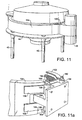
- FIG. 10 The manner in which a sheath such as is illustrated in Figures 4 to 6a can be mounted in a separator according to the invention is shown generically in Figures 10 , 11 and 12 .
- the separator is viewed from opposite sides.
- the motor 46 has a flange 150 secured to a mating flange on chassis 166 (see Figure 12 ).
- Chassis 166 corresponds to chassis 40 of Figures 2 , 2a and 3 and to chassis 110 of Figures 4 to 7 )
- the sheath 138 is formed in two halves 153, 154 each of which is a mirror image of the other and extends around almost one half of the chassis 166 save for the motor mount, against side faces of which adjacent ends of the sheath halves abut, as described below.
- the two halves 153, 154 of the sheath each have a pair of hinge plates 156 welded thereto, each plate of a pair having an integral bush 158 for receiving a steel hinge pin 160 which passes through both bushes of each pair.
- Each hinge pin 160 passes through a respective pin hole which is formed in a mounting block 164 which is welded to the chassis 166, and through a bearing aperture in a retaining plate 168 which is welded in situ between the mounting block 164 and the chassis 166.
- each half 153, 154 of the sheath is formed with a tongue portion 170, 172 respectively, which includes an out-turned flange portion 174, 176 respectively.
- These tongue portions 170, 172 are positioned flush against the outer surface of the chassis 166 between a magnetic keeper 178 mounted on the chassis 166 and a U-shaped horizontal hinge 180 welded or otherwise attached to the chassis.
- the two flange portions 174, 176 are in closely-separated relationship, the separation corresponding to the width of a slot 182 formed in a magnetic locking bar 184 which is used to clamp the two halves 153, 154 together on the chassis 166.
- the bar 184 is provided with a pair of hooks 186, 188 which hook over the horizontal hinge 180 to act as a pivot for the bar 184.
- the bar 184 has a magnet 190 inset into the body of the bar. This magnet 190 co-operates with the magnetic keeper 178 to hold the locking bar 184 in situ when it is moved from the position shown in Figure 11d to that shown in Figure 11e .
- the magnetic locking bar/keeper arrangement described above may use permanent magnets or electro-magnets.
- This construction permits ready locking of the two halves 153, 154 of the sheath 152 and quick release when it is required to uncouple them.
- the two halves can then be parted and swung back from the chassis 166 as shown in Figure 12 , and completely removed from the chassis of the separator by removal of the two hinge pins 160 and then lifting away from the chassis 166 with equal ease of remounting when the separator is again required for use.
- an over-centre latch may be used to secure the halves of the sheath together.
- the collar 150 of the motor is mounted on the mounting block 164.
- FIG. 12 shows a mobile version of the present invention.
- the cover of the separator has been removed and the two halves 153, 154 of the sheath released and are swung away from the chassis 166, either prior to removal of a screen frame or prior to closure of the two halves after replacement or cleaning of such a frame of frames.
- FIG. 12 there is also shown a variant of the locking system for locking the two halves 153, 154 against the chassis 166.
- the two halves 153, 154 instead of the tongue portions 170, 172 shown in Figures 11a and 11b , the two halves 153, 154 have tongue portions 194, 196 (194 not shown) which are turned inwards from the surface of the respective half 153, 154, with each tongue portion having a flange portion 198, 200 at right angles thereto.
- Pivotally mounted on the chassis 166 are two toggled hinge pins 202, 204 that can pivot between a horizontal position as shown in Figure 12 and an upright position parallel with the external face of the chassis 166 in which they engage the flange portions 196, 198 to retain the latter in position against the chassis.
- the two halves of the sheath 153, 154 can be quickly released, and subsequently coupled around the chassis 166.
- the ledge 114 does not have an internal annular wall 116 and the shelf portion 126 of the hopper rests on the ledge with the two frames in turn supported on the shelf portion.
- the at least one expandable element is provided by a plurality of pneumatic (or hydraulic) piston-and-cylinder arrangements 250 which are mounted on and secured to the base 112 and extend upwardly therefrom to engage the underside of the annular ledge 114.
- FIG 7 employs a sheath 246 which is formed by -a plurality of sheath segments 252 instead of the two sheath halves shown in Figures 10 , 11 and 12 .
- the manner in which the segments are mounted and can be moved is shown generally in Figures 13 and 14 , to which further reference will be made below.
- lower in-turned flange portions 253 of the sheath segments 252 are shown pivotally coupled to the piston-and-cylinder arrangements 250 by pivot pins 254 such that each segment can be pivoted from a non-engaging position to the position shown in Figure 7 .
- Each segment 252 has an upper in-turned flange portion 256 which overlaps a peripheral flange 146 of the cover and carries a resilient gasket 258 which is adapted to engage the peripheral flange 146 along the circumferential length of the segment.
- FIG. 8 and 9 A similar arrangement is shown in Figures 8 and 9 wherein, instead of being hingedly coupled to the piston-and-cylinder arrangements 250, the sheath segments 252 are each mounted on a plate 259 which is pivotally coupled to a hinge plate 260 which is itself similarly coupled to a bracket 262 welded to the underside of an in-turned flange 264 of the chassis 244.
- the positions of the pivotal couplings of the sheath segment plates to their respective hinge plates, and of the hinge plates to their respective brackets is such as to provide a toggle arrangement as shown in Figure 9 .
- an expandable element 266, similar to those used in earlier embodiments is located between the flange 264 and the annular shelf portion 126 of the hopper 124.
- Figures 13 and 14 The general construction using a plurality of sheath segments 252 can be seen in Figures 13 and 14 , and by comparison with the constructions shown in Figures 10 to 12 .
- the embodiment of Figures 13 and 14 comprises nine equally sized sheath segments 252.
- All of the sheath segments 252 are pivotal on mountings such as described with reference to Figures 7 to 9 , and are toggled when in the chassis enclosing position shown in Figure 13 , as described with reference to Figure 8 , or otherwise can be held in position, as with the embodiment of Figure 7 , by expansion of the piston-and-cylinder arrangements thereof.
- the segments then adopt the position shown in Figure 14 to permit the cover to be removed for the purpose of replacing or carrying out maintenance of the screens and/or the interior of the separator.
- Figure 15 shows an improvement of the first embodiment described above with reference to Figures 2 and 2a .
- Components of the apparatus which are the same or similar as in the first embodiment are identified with the same reference numerals.
- annular wall 62 welded or otherwise fixed to the annular ledge 60 as described and illustrated in the first embodiment and shown in Figures 2 and 2a
- there is an angle ring 300 providing an upwardly extending flange 301 corresponding to the annular wall 62 of the first embodiment, and a horizontal annular flange 302 which fits inside the outer wall of the chassis 40.
- a flat annular gasket 303 supports the angle ring 300 on the annular ledge 60.
- the angle ring 300 effectively provides the annular channel 64 of the first embodiment and as illustrated in Figures 2 and 2a , which contains the expandable element or annular bellows 66.
- the annular gasket 303 provides a good seal between the angle ring 300 and the annular ledge 60 of the chassis.
- annular ring 300 and the gasket 303 can be removed from the chassis structure to facilitate cleaning.
- FIG. 15 An additional modification in the embodiment of Figure 15 is the design of the annular shelf portion of the hopper 58.
- the hopper 58 has an outwardly extending flange portion 310 which is now of sufficient radial width that the radially inner part of the flange portion 310 can rest directly on the upper edge of the vertical flange 301 of the angle ring 300, when the bellows 66 is not inflated.
- the mesh frame 78 then rests directly on the upper surface of the annular flange 310, and the bellows 66 acts directly on the under surface of the annular flange 310.
- this design avoids the enclosed space defined by the annular shelf portion 70 and lower surface 76 of the hopper 58 in the first embodiment as illustrated in Figures 2 and 2a .
- Such enclosed spaces can be undesirable, especially when the separator is used for processing pharmaceuticals.
- the modified embodiment of Figure 15 is the same and operates in a similar fashion to the first embodiment as described previously.
- the chassis is mounted on the base by resilient mounts 210.
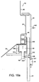
- Figure 16a illustrates the modified embodiment of Figure 15 with a further modification which allows positive leak prevention from the sieve.
- This embodiment is provided for illustrative purposes only.
- An additional circumferential seal 330 is provided between the sheath 50 and an outer surface of the chassis 40.
- this seal 330 may comprise an annular inflatable tube 331 mounted in a groove 332 formed in the outer face of the chassis wall.
- the tube 331 is connected by a supply conduit 333 to the pressurised gas inlet 69 for the main inflatable bellows 66, so that when the bellows 66 is inflated, so also is the tube 331 so as to form a gas-tight seal between the chassis 40 and the sheath 50.
- Other sealing arrangements may be used for seal.
- 330 such as a simple (non-inflatable) a-ring or annular gasket.
- a gas connection 340 is provided at an upper part of the sheath 50 so that the interior space defined by the sheath unit 50, the inner skirt 92 of the lid or cover, the gaskets 86 and 320, the periphery of the hopper 58, the bellows 66, the angle ring 300, the annular gasket 303, the annular ledge 60, and the chassis wall 40, can be pressurised, e.g. to 0.5 bar gauge. This over pressure then prevents any residual leakage from within the sieve product space through the seals between the cover 54 and the hopper 58. Also, leakage of possibly contaminating ambient air into the product space is prevented.
- a pressure sensing leak detection system may be provided if required to monitor the over-pressure in the region enclosed by the sheath 50.
- Figure 16b illustrates a variation of the arrangement for positive leak prevention using internal bayonet fittings comprising studs 48 engaging in slots provided in an internal flange 340 secured to the inside face of the sheath 50. This variation provides a smoother exterior surface to the assembled separator.
- the positive leak prevention system may also be applied to the separator with integrally formed cover and sheath of Figure 3 .
- an inflatable or O-ring seal such as seal 330 in Figures 16a and 16b may be provided between the sheath or extended skirt portion 50 of the cover of the Figure 3 embodiment and the chassis 40, conveniently at a location above the studs 48 of the bayonet fittings.
- Seal 86 for the sieve frame 82 makes a good seal with the shoulder 100 of the cover, when clamping pressure is applied by the bellows 66.
- a gas connection (not shown in Figure 3 ) can be provided through the skirt portion 50 to pressurise the space bounded by the skirt portion 50, the shoulder 100, the frames 82 and 78, the hopper 58, the bellows 66 and the chassis 40.
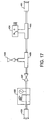
- Figure 17 illustrates a pneumatic control system which may be used with embodiments of this invention.
- a supply of pressurised air is connected at push connector 400 and is fed to the bellows 66 (together with the annular sealing tube 331 if fitted) by means of an outlet push connector 401.
- the pressure supplied to the sieve through the outlet 401 is controlled by a pressure regulator and gauge unit 402.
- a T-piece 403 in the pressure line supplies the applied pressure to a pressure sensor 404 which may be connected to disable the main sieve motor on detection of an applied pressure below a predetermined threshold, e.g. 5 bar.
- the pressure sensor 404 may be connected to one of the starter coils in the starter box of the separator.
- the pneumatic control system also includes a second T-piece 405 connecting to exhaust via an exhaust valve 406.
- an isolator valve 407 enables the inlet pressure supply to be isolated from the sieve.
- the bellows 66 of the separator unit is inflated to apply the required clamping pressure by closing the exhaust valve 406 and opening the isolation valve 407. These valves may be manual. Then, so long as the applied pressure as sensed by the sensor 404 exceeds the threshold (e.g. 5 bar) the sieve can be started in the usual way. If the applied pressure drops below the threshold, the sieve stops automatically and cannot be restarted until the pressure is restored.
- the threshold e.g. 5 bar
- an additional sensor may detect pressure change in the scaled region behind the sheath 50 and again stop the sieve until corrected.
- the sheath could be formed of various combinations as a hybrid of the structures shown in Figures 10 , 11 and 12 and Figures 13 and 14 whereby the sheath can be formed of segments which are themselves pivotally connected about vertical pivots to fold back about a hinge such as that shown in Figures 10 to 12 .
- the expandable elements of the various embodiments can be interchanged according to what is optimum for requirements.
- the expandable element is an inflatable continuous tube or annular bellows extending around the circumference of the screen frame.
- multiple lengths of inflatable tube or bellows elements may be used distributed around the screen frame to provide a substantially even clamping force.
- annular bellows may be replaced by an annular ring and at least two pneumatic or hydraulic rams operable to drive the ring to effect said clamping.
- Electro-magnets may be employed which can be switched on and off to apply clamping when required.
- Opposed permanent magnets may also be used and rotated from an opposing position when switching from repulsion (providing clamping pressure) to a released non-repelling position.
- the embodiment providing positive leak prevention which is described above and illustrated in Figure 16 , also incorporates the features of Figure 2 relating to securing and clamping together the various elements of the separator. It should be understood, however, that the positive leak prevention arrangement can be used with other designs of separator, for example designs which need not incorporate the one or more expandable elements to clamp the screen frame between a first bearing surface associated with the chassis of the separator and a second bearing surface associated with a clamping element.
- the positive leak prevention arrangement can be applied to sieves with prior art clamping arrangements sealing together the hopper and cover around the screen frame of the separator, modified to include a sleeve which is sealed to one of the hopper and cover so as to define the required enclosed space encompassing the clamp seals between the separator components. Other possibilities will be apparent to the skilled person.
Landscapes
- Combined Means For Separation Of Solids (AREA)
- Filters For Electric Vacuum Cleaners (AREA)
- Excavating Of Shafts Or Tunnels (AREA)
- Glass Compositions (AREA)
- Refuse Collection And Transfer (AREA)
- Superconductors And Manufacturing Methods Therefor (AREA)
- Separation By Low-Temperature Treatments (AREA)
- Filtering Of Dispersed Particles In Gases (AREA)
- Transition And Organic Metals Composition Catalysts For Addition Polymerization (AREA)
- Developing Agents For Electrophotography (AREA)
Applications Claiming Priority (2)
| Application Number | Priority Date | Filing Date | Title |
|---|---|---|---|
| GB0326514A GB2408006B (en) | 2003-11-13 | 2003-11-13 | Improvements in screen separators |
| PCT/GB2004/004813 WO2005049230A2 (en) | 2003-11-13 | 2004-11-12 | Improvements in screen separators |
Publications (2)
| Publication Number | Publication Date |
|---|---|
| EP1697065A2 EP1697065A2 (en) | 2006-09-06 |
| EP1697065B1 true EP1697065B1 (en) | 2010-01-06 |
Family
ID=29726506
Family Applications (1)
| Application Number | Title | Priority Date | Filing Date |
|---|---|---|---|
| EP04798533A Expired - Lifetime EP1697065B1 (en) | 2003-11-13 | 2004-11-12 | Improvements in screen separators |
Country Status (10)
| Country | Link |
|---|---|
| US (1) | US7721896B2 (https=) |
| EP (1) | EP1697065B1 (https=) |
| JP (1) | JP4668203B2 (https=) |
| CN (1) | CN1882394B (https=) |
| AT (1) | ATE454223T1 (https=) |
| DE (1) | DE602004025039D1 (https=) |
| DK (1) | DK1697065T3 (https=) |
| ES (1) | ES2337362T3 (https=) |
| GB (1) | GB2408006B (https=) |
| WO (1) | WO2005049230A2 (https=) |
Families Citing this family (31)
| Publication number | Priority date | Publication date | Assignee | Title |
|---|---|---|---|---|
| US20050242003A1 (en) | 2004-04-29 | 2005-11-03 | Eric Scott | Automatic vibratory separator |
| US8312995B2 (en) * | 2002-11-06 | 2012-11-20 | National Oilwell Varco, L.P. | Magnetic vibratory screen clamping |
| US7909172B2 (en) * | 2006-09-29 | 2011-03-22 | M-I L.L.C. | Composite screen with integral inflatable seal |
| US20080083566A1 (en) | 2006-10-04 | 2008-04-10 | George Alexander Burnett | Reclamation of components of wellbore cuttings material |
| US7938273B2 (en) * | 2007-09-14 | 2011-05-10 | M-I Llc | Magnetic clamping assembly |
| US9073104B2 (en) | 2008-08-14 | 2015-07-07 | National Oilwell Varco, L.P. | Drill cuttings treatment systems |
| US9079222B2 (en) | 2008-10-10 | 2015-07-14 | National Oilwell Varco, L.P. | Shale shaker |
| US8556083B2 (en) | 2008-10-10 | 2013-10-15 | National Oilwell Varco L.P. | Shale shakers with selective series/parallel flow path conversion |
| FR2946119B1 (fr) * | 2009-06-02 | 2015-03-20 | Areva Nc | Dispositif de connexion pour systeme de remplissage de jarres pour la fabrication de combustible nucleaire. |
| US20110198269A1 (en) * | 2010-02-16 | 2011-08-18 | Grant Young | Vibratory screen device |
| US20150165481A1 (en) * | 2010-10-28 | 2015-06-18 | Grant Young | Shaker Seal |
| US9221078B2 (en) * | 2010-11-19 | 2015-12-29 | M-I L.L.C. | Gasket for locating and sealing a screen in a round separator |
| KR101110206B1 (ko) * | 2011-05-02 | 2012-02-15 | 송명호 | 개폐가 용이하도록 완충기가 구비된 진동선별장치 |
| JP5972140B2 (ja) * | 2012-10-17 | 2016-08-17 | 株式会社ダルトン | 振動篩 |
| JP6054719B2 (ja) * | 2012-11-27 | 2016-12-27 | 株式会社ダルトン | 振動篩 |
| US9643111B2 (en) | 2013-03-08 | 2017-05-09 | National Oilwell Varco, L.P. | Vector maximizing screen |
| US9440807B2 (en) * | 2013-03-15 | 2016-09-13 | Ehs Solutions Llc | Nitrogen purge hopper |
| JP5636071B1 (ja) * | 2013-06-06 | 2014-12-03 | 明治機械株式会社 | 篩分け機並びにそれに用いる昇降枠及びその篩枠固定方法 |
| EP3151980B1 (en) * | 2014-06-06 | 2023-05-31 | M-I L.L.C. | Separator lifting apparatus and method |
| CN106583241A (zh) * | 2016-12-22 | 2017-04-26 | 新乡市振英机械设备有限公司 | 一种直线振动筛网架压紧结构 |
| US11525239B2 (en) * | 2018-04-30 | 2022-12-13 | Vermeer Manufacturing Company | Shaker assemblies having positioning devices |
| KR102148663B1 (ko) * | 2018-10-25 | 2020-08-27 | 한국해양과학기술원 | 시료 유실 방지 구조를 갖는 퇴적물 입자 분리 장치 |
| WO2021040995A1 (en) * | 2019-08-30 | 2021-03-04 | M-I L.L.C. | System and method for locking a weight assembly |
| CN110616588B (zh) * | 2019-09-16 | 2021-07-09 | 秦皇岛凡南纸业有限公司 | 一种造纸用成型模具 |
| CN110538793B (zh) * | 2019-09-29 | 2021-12-28 | 安徽兰奇丝网织造有限公司 | 一种快拆式筛网组件及其使用方法 |
| US12115557B2 (en) * | 2019-10-29 | 2024-10-15 | General Electric Company | Powder reclamation system for multiple metal powder processing devices |
| KR102125426B1 (ko) * | 2020-05-08 | 2020-06-22 | 한국해양과학기술원 | 시료 유실 방지 구조를 갖는 퇴적물 입자 분리 장치 |
| US11925887B2 (en) * | 2021-04-01 | 2024-03-12 | Ashley Gaertig | Separation tank device |
| CN114178172B (zh) * | 2021-11-25 | 2023-05-05 | 福建天马科技集团股份有限公司 | 一种用于石斑鱼苗料制备的筛分机 |
| CN118002460B (zh) * | 2024-01-29 | 2024-08-16 | 中国水利水电第十一工程局有限公司 | 一种骨料分筛机 |
| CN118142835B (zh) * | 2024-05-11 | 2024-07-16 | 福建省邵武市天源家居用品有限公司 | 一种玉瓷制备工艺及其制备用振动筛分装置 |
Family Cites Families (27)
| Publication number | Priority date | Publication date | Assignee | Title |
|---|---|---|---|---|
| GB1135402A (en) * | 1965-03-18 | 1968-12-04 | Russell Const Ltd | Improvements in or relating to vibratory mountings |
| US3422955A (en) | 1966-04-11 | 1969-01-21 | Smico Inc | Superimposed gyratory sifters |
| JPS51138771U (https=) * | 1975-04-30 | 1976-11-09 | ||
| US4082657A (en) * | 1976-01-19 | 1978-04-04 | Gage Ernest L | Separator apparatus |
| JPS541458A (en) * | 1977-06-04 | 1979-01-08 | Nobumasa Sugimoto | Vibrating screen that has stretching device of gauze by air pressure |
| SU839611A1 (ru) * | 1978-05-03 | 1981-06-23 | Всесоюзный Ордена Трудового Красногознамени Научно-Исследовательскийгорно-Металлургический Институтцветных Металлов | Нат жное устройство сита |
| GB2059807B (en) * | 1979-09-25 | 1983-05-05 | Russel Finex | Screen assembly locating ring for a circular sieving machine |
| JPS5948778U (ja) * | 1982-09-24 | 1984-03-31 | 武田薬品工業株式会社 | 振動篩機 |
| US4582597A (en) * | 1984-04-04 | 1986-04-15 | Sweco, Incorporated | Vibratory screen separator |
| GB8514983D0 (en) * | 1985-06-13 | 1985-07-17 | Thule United Ltd | Screen clamping |
| NO170199C (no) * | 1985-06-13 | 1992-09-23 | United Wire Ltd | Fremgangsmaate for loesbar fastgjoering av et siktelement i en holder i et vibrasjonssikteapparat, og vibrasjons-sikteapparat som et slikt siktelement kan monteres i |
| GB8514982D0 (en) * | 1985-06-13 | 1985-07-17 | Thule United Ltd | Screen clamping |
| JPH0141510Y2 (https=) * | 1986-06-17 | 1989-12-07 | ||
| CA1252424A (en) * | 1986-09-10 | 1989-04-11 | Wendy L. Jones | Five stage internal cell separator |
| SU1488027A1 (ru) * | 1987-11-30 | 1989-06-23 | Специальное Конструкторское Бюро По Подземному Самоходному Горному Оборудованию "Гормаш" | Нат жное устройство сита |
| JPH0366679U (https=) * | 1989-10-27 | 1991-06-28 | ||
| US5226546A (en) * | 1991-05-06 | 1993-07-13 | Sweco, Incorporated | Circular vibratory screen separator |
| GB2266475B (en) * | 1992-04-21 | 1995-08-16 | Alfa Laval Separation Ab | Mounting and tensioning arrangements for screens |
| CN2208454Y (zh) * | 1995-01-18 | 1995-09-27 | 励德芳 | 一种立式高效多层筛滤机 |
| WO1997047404A1 (en) * | 1996-06-13 | 1997-12-18 | Its Holdings Limited | Apparatus for attaching filter means to a frame |
| US5951864A (en) * | 1996-10-28 | 1999-09-14 | Emerson Electric Co. | Screening system |
| GB2327897B (en) * | 1996-10-28 | 1999-12-01 | Emerson Electric Co | Screening system |
| JP3664221B2 (ja) * | 1999-07-30 | 2005-06-22 | 株式会社サタケ | シフターのシーブ枠固定装置 |
| US6513665B1 (en) * | 1999-11-02 | 2003-02-04 | M-I L.L.C. | Screen mounting system |
| CZ12165U1 (cs) * | 2002-02-08 | 2002-04-09 | Jaroslav Bla®Ej | Kruhový sítový třídič |
| GB2394196A (en) * | 2002-10-17 | 2004-04-21 | Varco Int | Screen assembly for a shale shaker |
| US8245850B2 (en) * | 2003-11-13 | 2012-08-21 | Russell Finex Limited | Screen separators |
-
2003
- 2003-11-13 GB GB0326514A patent/GB2408006B/en not_active Expired - Fee Related
-
2004
- 2004-11-12 DK DK04798533.8T patent/DK1697065T3/da active
- 2004-11-12 DE DE602004025039T patent/DE602004025039D1/de not_active Expired - Lifetime
- 2004-11-12 JP JP2006538959A patent/JP4668203B2/ja not_active Expired - Fee Related
- 2004-11-12 AT AT04798533T patent/ATE454223T1/de not_active IP Right Cessation
- 2004-11-12 CN CN2004800336040A patent/CN1882394B/zh not_active Expired - Fee Related
- 2004-11-12 WO PCT/GB2004/004813 patent/WO2005049230A2/en not_active Ceased
- 2004-11-12 EP EP04798533A patent/EP1697065B1/en not_active Expired - Lifetime
- 2004-11-12 ES ES04798533T patent/ES2337362T3/es not_active Expired - Lifetime
- 2004-11-12 US US10/579,129 patent/US7721896B2/en not_active Expired - Lifetime
Also Published As
| Publication number | Publication date |
|---|---|
| WO2005049230A3 (en) | 2005-09-15 |
| DK1697065T3 (da) | 2010-05-10 |
| ES2337362T3 (es) | 2010-04-23 |
| GB2408006A (en) | 2005-05-18 |
| US7721896B2 (en) | 2010-05-25 |
| GB2408006B (en) | 2007-04-25 |
| ATE454223T1 (de) | 2010-01-15 |
| US20070084762A1 (en) | 2007-04-19 |
| JP4668203B2 (ja) | 2011-04-13 |
| DE602004025039D1 (de) | 2010-02-25 |
| EP1697065A2 (en) | 2006-09-06 |
| JP2007511344A (ja) | 2007-05-10 |
| CN1882394A (zh) | 2006-12-20 |
| WO2005049230A2 (en) | 2005-06-02 |
| CN1882394B (zh) | 2010-12-08 |
| GB0326514D0 (en) | 2003-12-17 |
Similar Documents
| Publication | Publication Date | Title |
|---|---|---|
| EP1697065B1 (en) | Improvements in screen separators | |
| US8245850B2 (en) | Screen separators | |
| US5456365A (en) | Vibratory screen separator | |
| US5791123A (en) | Method and apparatus for decanting hazardous substances into containers | |
| US5348063A (en) | Material handling system | |
| US5951864A (en) | Screening system | |
| CA1280083C (en) | Apparatus for emptying containers | |
| EP0768983B1 (en) | Liquid chemical dispensing and recirculating system | |
| US4648432A (en) | Vacuum apparatus for filling bags with particulate material including dust collector and recycling of collected material | |
| US5464035A (en) | Gate-type, side-ported, line blind valve | |
| GB1572430A (en) | Apparatus for filling a container | |
| JPH0646173B2 (ja) | 燃料タンクの漏れ検出方法と装置 | |
| JP2011201603A (ja) | コンテナ用ライナ、結合装置及びライナからの荷降し方法 | |
| JP2007511344A5 (https=) | ||
| US6698593B1 (en) | Vibratory screen separator | |
| US5332448A (en) | Apparatus for cleaning air filters | |
| JP2012091077A (ja) | 円型振動ふるい機における異物除去用のふるい網面点検機構 | |
| US6305412B1 (en) | Double acting pressure relief valve with low pressure seal | |
| KR102211230B1 (ko) | 자동 용접시스템 | |
| JPH01139389A (ja) | ホッパ装置 | |
| EP0709291A2 (en) | Filling head | |
| JP5025459B2 (ja) | バルク品用容器を空にする装置およびバルク品用容器 | |
| CN116840032B (zh) | 一种管道液压防爆试验装置 | |
| GB2562033A (en) | Method and apparatus for testing pressure relief valve | |
| US20030155289A1 (en) | Integrated filtration and media management system |
Legal Events
| Date | Code | Title | Description |
|---|---|---|---|
| PUAI | Public reference made under article 153(3) epc to a published international application that has entered the european phase |
Free format text: ORIGINAL CODE: 0009012 |
|
| 17P | Request for examination filed |
Effective date: 20060517 |
|
| AK | Designated contracting states |
Kind code of ref document: A2 Designated state(s): AT BE BG CH CY CZ DE DK EE ES FI FR GB GR HU IE IS IT LI LU MC NL PL PT RO SE SI SK TR |
|
| DAX | Request for extension of the european patent (deleted) | ||
| 17Q | First examination report despatched |
Effective date: 20080617 |
|
| GRAP | Despatch of communication of intention to grant a patent |
Free format text: ORIGINAL CODE: EPIDOSNIGR1 |
|
| GRAS | Grant fee paid |
Free format text: ORIGINAL CODE: EPIDOSNIGR3 |
|
| GRAA | (expected) grant |
Free format text: ORIGINAL CODE: 0009210 |
|
| AK | Designated contracting states |
Kind code of ref document: B1 Designated state(s): AT BE BG CH CY CZ DE DK EE ES FI FR GB GR HU IE IS IT LI LU MC NL PL PT RO SE SI SK TR |
|
| REG | Reference to a national code |
Ref country code: GB Ref legal event code: FG4D |
|
| REG | Reference to a national code |
Ref country code: CH Ref legal event code: EP |
|
| REG | Reference to a national code |
Ref country code: IE Ref legal event code: FG4D |
|
| REF | Corresponds to: |
Ref document number: 602004025039 Country of ref document: DE Date of ref document: 20100225 Kind code of ref document: P |
|
| REG | Reference to a national code |
Ref country code: ES Ref legal event code: FG2A Ref document number: 2337362 Country of ref document: ES Kind code of ref document: T3 |
|
| REG | Reference to a national code |
Ref country code: DK Ref legal event code: T3 |
|
| PG25 | Lapsed in a contracting state [announced via postgrant information from national office to epo] |
Ref country code: SI Free format text: LAPSE BECAUSE OF FAILURE TO SUBMIT A TRANSLATION OF THE DESCRIPTION OR TO PAY THE FEE WITHIN THE PRESCRIBED TIME-LIMIT Effective date: 20100106 |
|
| PG25 | Lapsed in a contracting state [announced via postgrant information from national office to epo] |
Ref country code: AT Free format text: LAPSE BECAUSE OF FAILURE TO SUBMIT A TRANSLATION OF THE DESCRIPTION OR TO PAY THE FEE WITHIN THE PRESCRIBED TIME-LIMIT Effective date: 20100106 |
|
| PG25 | Lapsed in a contracting state [announced via postgrant information from national office to epo] |
Ref country code: PT Free format text: LAPSE BECAUSE OF FAILURE TO SUBMIT A TRANSLATION OF THE DESCRIPTION OR TO PAY THE FEE WITHIN THE PRESCRIBED TIME-LIMIT Effective date: 20100506 Ref country code: IS Free format text: LAPSE BECAUSE OF FAILURE TO SUBMIT A TRANSLATION OF THE DESCRIPTION OR TO PAY THE FEE WITHIN THE PRESCRIBED TIME-LIMIT Effective date: 20100506 |
|
| PG25 | Lapsed in a contracting state [announced via postgrant information from national office to epo] |
Ref country code: PL Free format text: LAPSE BECAUSE OF FAILURE TO SUBMIT A TRANSLATION OF THE DESCRIPTION OR TO PAY THE FEE WITHIN THE PRESCRIBED TIME-LIMIT Effective date: 20100106 Ref country code: FI Free format text: LAPSE BECAUSE OF FAILURE TO SUBMIT A TRANSLATION OF THE DESCRIPTION OR TO PAY THE FEE WITHIN THE PRESCRIBED TIME-LIMIT Effective date: 20100106 |
|
| PG25 | Lapsed in a contracting state [announced via postgrant information from national office to epo] |
Ref country code: RO Free format text: LAPSE BECAUSE OF FAILURE TO SUBMIT A TRANSLATION OF THE DESCRIPTION OR TO PAY THE FEE WITHIN THE PRESCRIBED TIME-LIMIT Effective date: 20100106 Ref country code: SE Free format text: LAPSE BECAUSE OF FAILURE TO SUBMIT A TRANSLATION OF THE DESCRIPTION OR TO PAY THE FEE WITHIN THE PRESCRIBED TIME-LIMIT Effective date: 20100106 Ref country code: EE Free format text: LAPSE BECAUSE OF FAILURE TO SUBMIT A TRANSLATION OF THE DESCRIPTION OR TO PAY THE FEE WITHIN THE PRESCRIBED TIME-LIMIT Effective date: 20100106 Ref country code: CY Free format text: LAPSE BECAUSE OF FAILURE TO SUBMIT A TRANSLATION OF THE DESCRIPTION OR TO PAY THE FEE WITHIN THE PRESCRIBED TIME-LIMIT Effective date: 20100106 Ref country code: GR Free format text: LAPSE BECAUSE OF FAILURE TO SUBMIT A TRANSLATION OF THE DESCRIPTION OR TO PAY THE FEE WITHIN THE PRESCRIBED TIME-LIMIT Effective date: 20100407 |
|
| PLBE | No opposition filed within time limit |
Free format text: ORIGINAL CODE: 0009261 |
|
| STAA | Information on the status of an ep patent application or granted ep patent |
Free format text: STATUS: NO OPPOSITION FILED WITHIN TIME LIMIT |
|
| PG25 | Lapsed in a contracting state [announced via postgrant information from national office to epo] |
Ref country code: SK Free format text: LAPSE BECAUSE OF FAILURE TO SUBMIT A TRANSLATION OF THE DESCRIPTION OR TO PAY THE FEE WITHIN THE PRESCRIBED TIME-LIMIT Effective date: 20100106 Ref country code: CZ Free format text: LAPSE BECAUSE OF FAILURE TO SUBMIT A TRANSLATION OF THE DESCRIPTION OR TO PAY THE FEE WITHIN THE PRESCRIBED TIME-LIMIT Effective date: 20100106 Ref country code: BG Free format text: LAPSE BECAUSE OF FAILURE TO SUBMIT A TRANSLATION OF THE DESCRIPTION OR TO PAY THE FEE WITHIN THE PRESCRIBED TIME-LIMIT Effective date: 20100406 |
|
| 26N | No opposition filed |
Effective date: 20101007 |
|
| PGFP | Annual fee paid to national office [announced via postgrant information from national office to epo] |
Ref country code: DK Payment date: 20101124 Year of fee payment: 7 Ref country code: IE Payment date: 20101123 Year of fee payment: 7 |
|
| PG25 | Lapsed in a contracting state [announced via postgrant information from national office to epo] |
Ref country code: MC Free format text: LAPSE BECAUSE OF NON-PAYMENT OF DUE FEES Effective date: 20101130 |
|
| REG | Reference to a national code |
Ref country code: CH Ref legal event code: PL |
|
| PG25 | Lapsed in a contracting state [announced via postgrant information from national office to epo] |
Ref country code: LI Free format text: LAPSE BECAUSE OF NON-PAYMENT OF DUE FEES Effective date: 20101130 Ref country code: CH Free format text: LAPSE BECAUSE OF NON-PAYMENT OF DUE FEES Effective date: 20101130 |
|
| REG | Reference to a national code |
Ref country code: DK Ref legal event code: EBP |
|
| REG | Reference to a national code |
Ref country code: IE Ref legal event code: MM4A |
|
| PG25 | Lapsed in a contracting state [announced via postgrant information from national office to epo] |
Ref country code: HU Free format text: LAPSE BECAUSE OF FAILURE TO SUBMIT A TRANSLATION OF THE DESCRIPTION OR TO PAY THE FEE WITHIN THE PRESCRIBED TIME-LIMIT Effective date: 20100707 Ref country code: LU Free format text: LAPSE BECAUSE OF NON-PAYMENT OF DUE FEES Effective date: 20101112 |
|
| PG25 | Lapsed in a contracting state [announced via postgrant information from national office to epo] |
Ref country code: TR Free format text: LAPSE BECAUSE OF FAILURE TO SUBMIT A TRANSLATION OF THE DESCRIPTION OR TO PAY THE FEE WITHIN THE PRESCRIBED TIME-LIMIT Effective date: 20100106 Ref country code: IE Free format text: LAPSE BECAUSE OF NON-PAYMENT OF DUE FEES Effective date: 20111112 Ref country code: DK Free format text: LAPSE BECAUSE OF NON-PAYMENT OF DUE FEES Effective date: 20111130 |
|
| REG | Reference to a national code |
Ref country code: FR Ref legal event code: PLFP Year of fee payment: 12 |
|
| REG | Reference to a national code |
Ref country code: FR Ref legal event code: PLFP Year of fee payment: 13 |
|
| REG | Reference to a national code |
Ref country code: FR Ref legal event code: PLFP Year of fee payment: 14 |
|
| PGFP | Annual fee paid to national office [announced via postgrant information from national office to epo] |
Ref country code: NL Payment date: 20201117 Year of fee payment: 17 |
|
| PGFP | Annual fee paid to national office [announced via postgrant information from national office to epo] |
Ref country code: ES Payment date: 20201202 Year of fee payment: 17 |
|
| PGFP | Annual fee paid to national office [announced via postgrant information from national office to epo] |
Ref country code: BE Payment date: 20201117 Year of fee payment: 17 |
|
| PGFP | Annual fee paid to national office [announced via postgrant information from national office to epo] |
Ref country code: FR Payment date: 20211119 Year of fee payment: 18 Ref country code: DE Payment date: 20211119 Year of fee payment: 18 |
|
| PGFP | Annual fee paid to national office [announced via postgrant information from national office to epo] |
Ref country code: IT Payment date: 20211122 Year of fee payment: 18 |
|
| REG | Reference to a national code |
Ref country code: NL Ref legal event code: MM Effective date: 20211201 |
|
| PG25 | Lapsed in a contracting state [announced via postgrant information from national office to epo] |
Ref country code: BE Free format text: LAPSE BECAUSE OF NON-PAYMENT OF DUE FEES Effective date: 20211130 |
|
| REG | Reference to a national code |
Ref country code: BE Ref legal event code: MM Effective date: 20211130 |
|
| PG25 | Lapsed in a contracting state [announced via postgrant information from national office to epo] |
Ref country code: NL Free format text: LAPSE BECAUSE OF NON-PAYMENT OF DUE FEES Effective date: 20211201 |
|
| REG | Reference to a national code |
Ref country code: ES Ref legal event code: FD2A Effective date: 20230210 |
|
| PG25 | Lapsed in a contracting state [announced via postgrant information from national office to epo] |
Ref country code: ES Free format text: LAPSE BECAUSE OF NON-PAYMENT OF DUE FEES Effective date: 20211113 |
|
| REG | Reference to a national code |
Ref country code: DE Ref legal event code: R119 Ref document number: 602004025039 Country of ref document: DE |
|
| PG25 | Lapsed in a contracting state [announced via postgrant information from national office to epo] |
Ref country code: IT Free format text: LAPSE BECAUSE OF NON-PAYMENT OF DUE FEES Effective date: 20221112 Ref country code: DE Free format text: LAPSE BECAUSE OF NON-PAYMENT OF DUE FEES Effective date: 20230601 |
|
| PG25 | Lapsed in a contracting state [announced via postgrant information from national office to epo] |
Ref country code: FR Free format text: LAPSE BECAUSE OF NON-PAYMENT OF DUE FEES Effective date: 20221130 |
|
| PGFP | Annual fee paid to national office [announced via postgrant information from national office to epo] |
Ref country code: GB Payment date: 20231117 Year of fee payment: 20 |
|
| REG | Reference to a national code |
Ref country code: GB Ref legal event code: PE20 Expiry date: 20241111 |
|
| PG25 | Lapsed in a contracting state [announced via postgrant information from national office to epo] |
Ref country code: GB Free format text: LAPSE BECAUSE OF EXPIRATION OF PROTECTION Effective date: 20241111 |
|
| PG25 | Lapsed in a contracting state [announced via postgrant information from national office to epo] |
Ref country code: GB Free format text: LAPSE BECAUSE OF EXPIRATION OF PROTECTION Effective date: 20241111 |