EP1696297A2 - Robot cleaner and method of control thereof - Google Patents
Robot cleaner and method of control thereof Download PDFInfo
- Publication number
- EP1696297A2 EP1696297A2 EP06290153A EP06290153A EP1696297A2 EP 1696297 A2 EP1696297 A2 EP 1696297A2 EP 06290153 A EP06290153 A EP 06290153A EP 06290153 A EP06290153 A EP 06290153A EP 1696297 A2 EP1696297 A2 EP 1696297A2
- Authority
- EP
- European Patent Office
- Prior art keywords
- cleaning
- unit
- area
- cleaning area
- travel
- Prior art date
- Legal status (The legal status is an assumption and is not a legal conclusion. Google has not performed a legal analysis and makes no representation as to the accuracy of the status listed.)
- Withdrawn
Links
Images



Classifications
-
- G—PHYSICS
- G05—CONTROLLING; REGULATING
- G05D—SYSTEMS FOR CONTROLLING OR REGULATING NON-ELECTRIC VARIABLES
- G05D1/00—Control of position, course, altitude or attitude of land, water, air or space vehicles, e.g. using automatic pilots
- G05D1/02—Control of position or course in two dimensions
- G05D1/021—Control of position or course in two dimensions specially adapted to land vehicles
- G05D1/0268—Control of position or course in two dimensions specially adapted to land vehicles using internal positioning means
- G05D1/0272—Control of position or course in two dimensions specially adapted to land vehicles using internal positioning means comprising means for registering the travel distance, e.g. revolutions of wheels
-
- A—HUMAN NECESSITIES
- A01—AGRICULTURE; FORESTRY; ANIMAL HUSBANDRY; HUNTING; TRAPPING; FISHING
- A01K—ANIMAL HUSBANDRY; AVICULTURE; APICULTURE; PISCICULTURE; FISHING; REARING OR BREEDING ANIMALS, NOT OTHERWISE PROVIDED FOR; NEW BREEDS OF ANIMALS
- A01K97/00—Accessories for angling
- A01K97/12—Signalling devices, e.g. tip-up devices
-
- A—HUMAN NECESSITIES
- A01—AGRICULTURE; FORESTRY; ANIMAL HUSBANDRY; HUNTING; TRAPPING; FISHING
- A01K—ANIMAL HUSBANDRY; AVICULTURE; APICULTURE; PISCICULTURE; FISHING; REARING OR BREEDING ANIMALS, NOT OTHERWISE PROVIDED FOR; NEW BREEDS OF ANIMALS
- A01K97/00—Accessories for angling
- A01K97/10—Supports for rods
-
- G—PHYSICS
- G05—CONTROLLING; REGULATING
- G05D—SYSTEMS FOR CONTROLLING OR REGULATING NON-ELECTRIC VARIABLES
- G05D1/00—Control of position, course, altitude or attitude of land, water, air or space vehicles, e.g. using automatic pilots
- G05D1/02—Control of position or course in two dimensions
- G05D1/021—Control of position or course in two dimensions specially adapted to land vehicles
- G05D1/0227—Control of position or course in two dimensions specially adapted to land vehicles using mechanical sensing means, e.g. for sensing treated area
-
- G—PHYSICS
- G05—CONTROLLING; REGULATING
- G05D—SYSTEMS FOR CONTROLLING OR REGULATING NON-ELECTRIC VARIABLES
- G05D1/00—Control of position, course, altitude or attitude of land, water, air or space vehicles, e.g. using automatic pilots
- G05D1/02—Control of position or course in two dimensions
- G05D1/021—Control of position or course in two dimensions specially adapted to land vehicles
- G05D1/0231—Control of position or course in two dimensions specially adapted to land vehicles using optical position detecting means
- G05D1/0242—Control of position or course in two dimensions specially adapted to land vehicles using optical position detecting means using non-visible light signals, e.g. IR or UV signals
-
- G—PHYSICS
- G05—CONTROLLING; REGULATING
- G05D—SYSTEMS FOR CONTROLLING OR REGULATING NON-ELECTRIC VARIABLES
- G05D1/00—Control of position, course, altitude or attitude of land, water, air or space vehicles, e.g. using automatic pilots
- G05D1/02—Control of position or course in two dimensions
- G05D1/021—Control of position or course in two dimensions specially adapted to land vehicles
- G05D1/0255—Control of position or course in two dimensions specially adapted to land vehicles using acoustic signals, e.g. ultra-sonic singals
-
- Y—GENERAL TAGGING OF NEW TECHNOLOGICAL DEVELOPMENTS; GENERAL TAGGING OF CROSS-SECTIONAL TECHNOLOGIES SPANNING OVER SEVERAL SECTIONS OF THE IPC; TECHNICAL SUBJECTS COVERED BY FORMER USPC CROSS-REFERENCE ART COLLECTIONS [XRACs] AND DIGESTS
- Y10—TECHNICAL SUBJECTS COVERED BY FORMER USPC
- Y10S—TECHNICAL SUBJECTS COVERED BY FORMER USPC CROSS-REFERENCE ART COLLECTIONS [XRACs] AND DIGESTS
- Y10S81/00—Tools
- Y10S81/01—Tool-support adjuncts
Definitions
- the present invention relates to a robot cleaner and a controlling method thereof. More particularly, the present invention relates to a robot cleaner, its cleaning travel pattern, that is preferably rectangular-spiral and variable depending on the shapes of the cleaning surfaces, and a controlling method thereof.
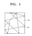
- FIG. 1 shows an example of a conventional random cleaning method.
- reference numeral 11a indicates a cleaning area
- reference numeral 11b indicates a random cleaning pattern.
- the random cleaning method a cleaner maneuvers in a cleaning area without any rules for performing the cleaning.
- the pattern is analogous to a rotating ball colliding with a wall and springing out in a V shape.
- the random cleaning method can result in a number of areas remaining uncleaned.
- FIG. 2 is an example of a conventional cleaning method, as disclosed in Japanese No. H5-161577, laid-open on June 29, H5 (1993), and entitled Robot Cleaner.
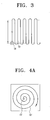
- FIG. 3 is a view of a cleaning trace pattern performed by the construction of FIG. 2.
- a robot cleaner comprises a travel steering means 3 moving a cleaning body; a travel distance detecting means 5; a direction detecting means 4 detecting direction of the body; a determination process means 8 receiving signals from the travel distance detecting means 5 and the direction detecting means 4 to output a travel signal to the travel steering means 3; a cleaning means 2; a power source 1; a travel distance setting means 6; and a number of U-turns setting means 7.
- the robot cleaner travels straight by use of the direction detecting means 4 and the travel steering means 3, makes U-turns by use of the direction detecting means 4 and the travel steering means 3, and determines whether the number of U-turns and the straight travel distance reach certain values to perform cleaning.
- the reference numeral 18 depicts a robot cleaner body
- the reference numeral 19 depicts a travel pattern.
- the robot cleaner travels in a simple stripe travel pattern, which often fails to efficiently cover the cleaning area.
- FIGS. 4A to 4C are views of a conventional concentric-spiral cleaning travel pattern.
- the reference numeral 18' depicts a robot cleaner body
- the reference numeral 19' depicts a concentric-spiral cleaning travel pattern
- E1 and E2 depict uncleaned areas.
- the cleaning travel pattern 19' forms concentric circles such that only areas having the same diameter as the circles can be covered. Accordingly, uncleaned areas E1 and E2 remain particularly when the cleaning area is rectangular, as seen in FIGS. 4B and 4C.
- a first aspect of the present invention is to provide a robot vacuum cleaner which has a rectangular-spiral cleaning travel pattern and variably applies the cleaning travel pattern to cover the entire cleaning area.
- a second aspect of the present invention is to provide a controlling method of the aforementioned robot cleaner which has a rectangular-spiral travel pattern.
- a robot vacuum cleaner comprising: a driving unit moving a body on a cleaning surface; a cleaning area detecting unit detecting an area of the cleaning surface; and a central processing unit calculating a spiral cleaning travel pattern corresponding to the shape of each cleaning area based on information from the cleaning area detecting area and outputting a cleaning travel signal to the driving unit.
- the cleaning travel pattern may comprise a rectangular-spiral, and the rectangle may comprise an oblong or a square.
- the central processing unit may comprise a determination unit receiving a detecting signal from the cleaning area detecting unit to determine a cleaning area; and a cleaning travel signal processing unit calculating a cleaning travel pattern corresponding to the cleaning area determined by the determination unit and outputting a cleaning travel signal corresponding to the cleaning travel pattern to the driving unit.
- the detecting of the cleaning area can be performed while cleaning or when starting the cleaning.
- a method of controlling the robot vacuum cleaner comprising the steps of detecting a cleaning area; calculating a spiral cleaning travel pattern corresponding to the detected cleaning area; and outputting the calculated cleaning travel pattern signal to perform the cleaning.
- the method may further comprise the step of performing an initial cleaning before the detecting the cleaning area.
- the cleaning travel pattern can be a rectangular-spiral, and the rectangle comprises can be oblong or a square.
- a robot cleaner applied according to an embodiment of the present invention as described above produces a cleaning travel pattern that is preferably rectangular-spiral and a cleaning travel pattern that is variably applied corresponding to the cleaning area, thereby increasing the cleaning efficiency.
- FIG. 1 is a diagrammatic view of a conventional random cleaning method pattern
- FIG. 2 is a flowchart of a conventional cleaning method
- FIG. 3 is a diagrammatic view of a cleaning travel pattern performed by the method of FIG. 2;
- FIGS. 4A to 4C are diagrammatic views of conventional concentric-spiral cleaning travel patterns
- FIG. 5 is a schematic view of a robot cleaner according to an embodiment of the present invention.
- FIG. 6 is a block diagram of the robot cleaner illustrated in FIG. 5;
- FIG. 7 is a flowchart of a cleaning operation of the robot cleaner illustrated in FIG. 5;
- FIG. 8 is a flowchart of a control method of a robot cleaner according to another embodiment of the present invention.
- FIGS. 9A to 9C are diagrammatic views of examples of cleaning areas applying the cleaning travel pattern according to an embodiment of the present invention.
- a robot cleaner 100 comprises a body 101, a cleaning unit 110, a cleaning area detecting unit 310, a driving unit 150, a travel distance detecting unit 170, a central processing unit 330, a battery 210, and a manipulation unit 230.
- the body 101 may be configured as a cylinder, and includes the cleaning unit 110 for collecting dust or contaminants from a cleaning surface.
- the cleaning unit 110 may consist of, for example, a suction brush 115 and a suction pipe for drawing in dust (not shown) or contaminants from the cleaning surface, a suction motor 113 for generating a suction force, and a dust chamber (not shown) for collecting the drawn in dust and contaminants.
- the cleaning area detecting unit 310 is mounted to a front side of the body 101 to detect a cleaning area by sensing an obstacle, such as a wall.
- the cleaning area detecting unit 310 comprises a cleaning area detecting sensor 311 for detecting the cleaning area.
- the cleaning area detecting sensor 311 may be, for example, a light sensor 311 a in which an element emitting infrared rays and a light receiving element receiving reflected light are paired.
- the cleaning area detecting sensor 311 may be an ultrasonic wave sensor (not shown) which is capable of emitting ultrasonic waves and receiving reflected ultrasonic waves.
- the cleaning area detecting sensor 311 may be a bump sensor 311b disposed along an outer circumference of the front side of the body 101 for sensing an obstacle. The bump sensor 311b activates a tact switch in the bumper which senses an obstacle when the bumper collides with the obstacle while traveling.
- the driving unit 150 for controlling the wheels of the robot cleaner 100 is mounted to the body 101.
- the driving unit 150 comprises a left wheel motor 153L and a right wheel motor 153R controlling a left wheel 151L and a right wheel 151R, respectively.
- the driving unit 150 receives a signal from the central processing unit 330 to change the direction of the left wheel 151L and the right wheel 151R while moving along the cleaning travel pattern.
- the travel distance detecting unit 170 comprises a left wheel encoder 171 L and a right wheel encoder 171 R for sensing the status of each of the left wheel motor 153L and the right wheel motor 153R.
- the central processing unit 330 controls the general operation of the robot cleaner 100, and the battery 210 provides power and is charged by an exterior charging device. Additionally, the manipulation unit 230 (FIG. 6) is disposed in the body 101 and inputs a manipulation requirement of the robot cleaner to the central processing unit 330 according to the user's manipulation.
- the robot cleaner 100 comprises the cleaning unit 110, the cleaning area detecting unit 310, the driving unit 150, the travel distance detecting unit 170, the central processing unit 330, the battery 210, and the manipulation unit 230, and a memory 250 and a communication unit 270.
- the cleaning unit 110 comprises a suction motor driving part 111 receiving a cleaning signal from the central processing unit 330 to drive the suction motor 113, and the suction brush 115 receiving the driving force of the suction motor 113 to be driven.
- the cleaning area detecting unit 310 senses an obstacle, such as a wall in front of the robot cleaner 100, and inputs the information to the central processing unit 330.
- the unit 310 comprises a cleaning area detecting driving part 313 that receives a signal from the central processing unit 330 to drive the cleaning area detecting sensor 311.
- the cleaning area detecting sensor 311 may initially travel along a wall to sense the cleaning area, or may sense an obstacle to detect the cleaning area.
- the cleaning area detecting sensor 311 may be, for example, a light sensor, an infrared ray sensor, or a bump sensor.
- the driving unit 150 comprises the left wheel motor driving part 153L and the right wheel motor driving part 153R that receive travel signals from the central processing unit 330 and output driving signals to the left wheel motor 155L and the right wheel motor 155R to drive the left wheel 151L and the right wheel 151R.
- the travel distance detecting unit 170 sends a travel distance of the robot cleaner 100 to the central processing unit 330, and comprises the left wheel encoder 171L and the right wheel encoder 171R for determining the number of rotations of the left wheel motor 155L and the right wheel motor 155R.
- the central processing unit 330 controls the general cleaning operation of the robot cleaner 100, and comprises a determination unit 331 determining a cleaning area by the cleaning area detecting unit 310, and a cleaning travel signal processing unit 333 calculating a cleaning travel pattern of the robot cleaner 100 based on the information of the determination unit 331 and outputting a cleaning travel pattern signal to the driving unit 150.
- the cleaning travel pattern may be spiral, and preferably rectangular-spiral, to more efficiently cover a cleaning area.
- the central processing unit 330 further comprises a distance count unit 335 calculating a travel distance based on the number of rotations of the left wheel motor 155L and the right wheel motor 155R transmitted via the left wheel encoder 171 L and the right wheel encoder 171 R.
- the manipulation unit 230 controls each operation of the robot cleaner 100 and comprises various manipulation switches.
- the memory 250 is built-in or removable to control the entire operation of the robot cleaner 100, and includes EPROM (erasable programmable read-only memory), EEPROM (electrically erasable programmable read-only memory) and RAM (random access memory).
- the communication unit 270 emits data in the robot cleaner 100, or transmits received exterior data to the central processing unit 330.
- the robot cleaner 100 first performs an initial cleaning at step S100.
- the central processing unit 330 sends a driving signal to the cleaning unit 110 and simultaneously sends a driving signal to the driving unit 150 upon receipt of a cleaning start signal from the manipulation unit 230.
- the suction motor driving part 111 drives the suction motor 113 to operate the suction brush 115. Dust or debris of the cleaning surface are drawn in via the suction brush 115 and moved into the dust chamber of the cleaner.
- the left wheel motor 155L or the right wheel motor 155R is driven to move the left wheel 151L or the right wheel 151R along the cleaning travel pattern such that the certain cleaning is performed.
- the central processing unit 330 sends the cleaning area detection signal to the cleaning area detection driving part 313 and operates the cleaning area detecting sensor 311 to detect the cleaning area while cleaning at step S300.
- the determination unit 331 of the central processing unit 330 determines the shape of the cleaning area
- the cleaning travel signal processing unit 333 calculates a cleaning travel pattern corresponding to the shape and sends a cleaning travel signal to the driving unit 150 at step S500.
- the cleaning travel pattern is preferably a rectangular-spiral pattern 901, as seen in FIG. 9B, and may be oblong-spiral or square-spiral pattern, as seen in FIGS. 9A and 9C, respectively.
- the driving unit 150 having received the signal from the cleaning travel signal processing unit 333 travels along a cleaning travel pattern and correspondingly to the shape of the cleaning area to perform the cleaning at step S700. If the cleaning is completed at step S700, then the cleaning operation is terminated at step S900. If the cleaning is not complete, step S700 is repeated.
- FIG. 8 is a view of a control method of a robot cleaner according to another embodiment of the present invention.
- detecting the cleaning area is performed prior to the start of cleaning.
- the cleaning area is detected while cleaning according to the method of FIG. 7, except that the cleaning area is detected at step S110 before starting the cleaning at step S100. Accordingly, the same reference numerals are used for the same processes with FIG. 7, and the detailed description thereof will be omitted.
Landscapes
- Environmental Sciences (AREA)
- Life Sciences & Earth Sciences (AREA)
- Engineering & Computer Science (AREA)
- Radar, Positioning & Navigation (AREA)
- Biodiversity & Conservation Biology (AREA)
- Aviation & Aerospace Engineering (AREA)
- Animal Husbandry (AREA)
- Remote Sensing (AREA)
- Physics & Mathematics (AREA)
- General Physics & Mathematics (AREA)
- Automation & Control Theory (AREA)
- Electric Vacuum Cleaner (AREA)
- Control Of Position, Course, Altitude, Or Attitude Of Moving Bodies (AREA)
- Electric Suction Cleaners (AREA)
Abstract
A robot vacuum cleaner (100) that comprises a driving unit (150) moving a body (101) on a cleaning surface; a cleaning area detecting unit (310) detecting an area of the cleaning surface; and a central processing unit (330) calculating a spiral cleaning travel pattern corresponding to a shape of each cleaning area based on the information detected by the cleaning area detecting unit to output a cleaning travel signal corresponding the calculated cleaning travel pattern to the driving unit. The cleaning travel pattern can be variable applied depending on a shape of each cleaning area such that the coverage ratio of the cleaning area can increase.
Description
- This application claims priority under 35 U.S.C. § 119 to Korean Patent Application No. 2005-15775, filed on February 25, 2005, in the Korean Intellectual Property Office, the disclosure of which is incorporated herein by reference in its entirety. This application may be related to commonly owned U.S. Patent Application Serial No. 11/288,090, filed on November 29, 2005 claiming priority to Korean Patent Application No. 2005-15468 (116511-00180), filed February 24, 2005, and commonly owned U.S. Patent Application Serial No. 10/804,077, filed March 19, 2004, the subject matter of each of which is herein incorporated by reference.
- The present invention relates to a robot cleaner and a controlling method thereof. More particularly, the present invention relates to a robot cleaner, its cleaning travel pattern, that is preferably rectangular-spiral and variable depending on the shapes of the cleaning surfaces, and a controlling method thereof.
- Recently, a market for domestic robots, including various types of robot cleaners, has formed and is growing. It is important for robot cleaners to be able to sufficiently clean an entire area without leaving any areas uncleaned. That requires the robot cleaner to recognize any uncleaned areas and clean those areas.
- Conventional cleaning methods of robot cleaners are typically either a random sweeping method or a pattern sweeping method. FIG. 1 shows an example of a conventional random cleaning method. Referring to FIG. 1,
reference numeral 11a indicates a cleaning area, andreference numeral 11b indicates a random cleaning pattern. For the random cleaning method, a cleaner maneuvers in a cleaning area without any rules for performing the cleaning. The pattern is analogous to a rotating ball colliding with a wall and springing out in a V shape. The random cleaning method can result in a number of areas remaining uncleaned. - FIG. 2 is an example of a conventional cleaning method, as disclosed in Japanese No. H5-161577, laid-open on June 29, H5 (1993), and entitled Robot Cleaner. FIG. 3 is a view of a cleaning trace pattern performed by the construction of FIG. 2.
- Referring to FIGS. 2 and 3, a robot cleaner comprises a travel steering means 3 moving a cleaning body; a travel distance detecting means 5; a direction detecting means 4 detecting direction of the body; a determination process means 8 receiving signals from the travel distance detecting means 5 and the direction detecting means 4 to output a travel signal to the travel steering means 3; a cleaning means 2; a
power source 1; a travel distance setting means 6; and a number of U-turns setting means 7. The robot cleaner travels straight by use of the direction detecting means 4 and the travel steering means 3, makes U-turns by use of the direction detecting means 4 and the travel steering means 3, and determines whether the number of U-turns and the straight travel distance reach certain values to perform cleaning. In FIG. 3, thereference numeral 18 depicts a robot cleaner body, and thereference numeral 19 depicts a travel pattern. As seen in FIG. 3, the robot cleaner travels in a simple stripe travel pattern, which often fails to efficiently cover the cleaning area. - FIGS. 4A to 4C are views of a conventional concentric-spiral cleaning travel pattern. Referring to FIGS. 4A to 4C, the reference numeral 18' depicts a robot cleaner body, the reference numeral 19' depicts a concentric-spiral cleaning travel pattern, and E1 and E2 depict uncleaned areas. The cleaning travel pattern 19' forms concentric circles such that only areas having the same diameter as the circles can be covered. Accordingly, uncleaned areas E1 and E2 remain particularly when the cleaning area is rectangular, as seen in FIGS. 4B and 4C.
- Accordingly, a first aspect of the present invention is to provide a robot vacuum cleaner which has a rectangular-spiral cleaning travel pattern and variably applies the cleaning travel pattern to cover the entire cleaning area.
- A second aspect of the present invention is to provide a controlling method of the aforementioned robot cleaner which has a rectangular-spiral travel pattern.
- In order to achieve the first aspect, there is provided a robot vacuum cleaner, comprising: a driving unit moving a body on a cleaning surface; a cleaning area detecting unit detecting an area of the cleaning surface; and a central processing unit calculating a spiral cleaning travel pattern corresponding to the shape of each cleaning area based on information from the cleaning area detecting area and outputting a cleaning travel signal to the driving unit. The cleaning travel pattern may comprise a rectangular-spiral, and the rectangle may comprise an oblong or a square.
- The central processing unit may comprise a determination unit receiving a detecting signal from the cleaning area detecting unit to determine a cleaning area; and a cleaning travel signal processing unit calculating a cleaning travel pattern corresponding to the cleaning area determined by the determination unit and outputting a cleaning travel signal corresponding to the cleaning travel pattern to the driving unit. The detecting of the cleaning area can be performed while cleaning or when starting the cleaning.
- To achieve the second aspect, there is provided a method of controlling the robot vacuum cleaner comprising the steps of detecting a cleaning area; calculating a spiral cleaning travel pattern corresponding to the detected cleaning area; and outputting the calculated cleaning travel pattern signal to perform the cleaning. The method may further comprise the step of performing an initial cleaning before the detecting the cleaning area. The cleaning travel pattern can be a rectangular-spiral, and the rectangle comprises can be oblong or a square.
- A robot cleaner applied according to an embodiment of the present invention as described above produces a cleaning travel pattern that is preferably rectangular-spiral and a cleaning travel pattern that is variably applied corresponding to the cleaning area, thereby increasing the cleaning efficiency.
- The above and other aspects, features and advantages of the present invention will be more apparent from the following detailed description taken with reference to the accompanying drawings, in which:
- FIG. 1 is a diagrammatic view of a conventional random cleaning method pattern;
- FIG. 2 is a flowchart of a conventional cleaning method;
- FIG. 3 is a diagrammatic view of a cleaning travel pattern performed by the method of FIG. 2;
- FIGS. 4A to 4C are diagrammatic views of conventional concentric-spiral cleaning travel patterns;
- FIG. 5 is a schematic view of a robot cleaner according to an embodiment of the present invention;
- FIG. 6 is a block diagram of the robot cleaner illustrated in FIG. 5;
- FIG. 7 is a flowchart of a cleaning operation of the robot cleaner illustrated in FIG. 5;
- FIG. 8 is a flowchart of a control method of a robot cleaner according to another embodiment of the present invention; and
- FIGS. 9A to 9C are diagrammatic views of examples of cleaning areas applying the cleaning travel pattern according to an embodiment of the present invention.
- Certain embodiments of the present invention will be described in greater detail with reference to the accompanying drawings.
- In the following description, the same drawing reference numerals are used for the same elements. The matters defined in the description, such as a detailed construction and elements, are only provided to assist in a comprehensive understanding of the invention. Thus, it is apparent that the present invention can be carried out without those defined matters. Also, well-known functions or constructions are not described in detail because they would obscure the invention in unnecessary detail.
- Referring to FIG. 5, a
robot cleaner 100 comprises abody 101, acleaning unit 110, a cleaningarea detecting unit 310, adriving unit 150, a traveldistance detecting unit 170, acentral processing unit 330, abattery 210, and amanipulation unit 230. - The
body 101 may be configured as a cylinder, and includes thecleaning unit 110 for collecting dust or contaminants from a cleaning surface. Thecleaning unit 110 may consist of, for example, asuction brush 115 and a suction pipe for drawing in dust (not shown) or contaminants from the cleaning surface, asuction motor 113 for generating a suction force, and a dust chamber (not shown) for collecting the drawn in dust and contaminants. - The cleaning
area detecting unit 310 is mounted to a front side of thebody 101 to detect a cleaning area by sensing an obstacle, such as a wall. The cleaningarea detecting unit 310 comprises a cleaningarea detecting sensor 311 for detecting the cleaning area. The cleaningarea detecting sensor 311 may be, for example, alight sensor 311 a in which an element emitting infrared rays and a light receiving element receiving reflected light are paired. The cleaningarea detecting sensor 311 may be an ultrasonic wave sensor (not shown) which is capable of emitting ultrasonic waves and receiving reflected ultrasonic waves. Alternatively, the cleaningarea detecting sensor 311 may be abump sensor 311b disposed along an outer circumference of the front side of thebody 101 for sensing an obstacle. Thebump sensor 311b activates a tact switch in the bumper which senses an obstacle when the bumper collides with the obstacle while traveling. - The driving
unit 150 for controlling the wheels of therobot cleaner 100 is mounted to thebody 101. The drivingunit 150 comprises aleft wheel motor 153L and aright wheel motor 153R controlling aleft wheel 151L and aright wheel 151R, respectively. The drivingunit 150 receives a signal from thecentral processing unit 330 to change the direction of theleft wheel 151L and theright wheel 151R while moving along the cleaning travel pattern. The traveldistance detecting unit 170 comprises aleft wheel encoder 171 L and aright wheel encoder 171 R for sensing the status of each of theleft wheel motor 153L and theright wheel motor 153R. - The
central processing unit 330 controls the general operation of therobot cleaner 100, and thebattery 210 provides power and is charged by an exterior charging device. Additionally, the manipulation unit 230 (FIG. 6) is disposed in thebody 101 and inputs a manipulation requirement of the robot cleaner to thecentral processing unit 330 according to the user's manipulation. - Referring to FIG. 6, the
robot cleaner 100 comprises thecleaning unit 110, the cleaningarea detecting unit 310, the drivingunit 150, the traveldistance detecting unit 170, thecentral processing unit 330, thebattery 210, and themanipulation unit 230, and amemory 250 and acommunication unit 270. - The
cleaning unit 110 comprises a suctionmotor driving part 111 receiving a cleaning signal from thecentral processing unit 330 to drive thesuction motor 113, and thesuction brush 115 receiving the driving force of thesuction motor 113 to be driven. - The cleaning
area detecting unit 310 senses an obstacle, such as a wall in front of therobot cleaner 100, and inputs the information to thecentral processing unit 330. Theunit 310 comprises a cleaning area detecting drivingpart 313 that receives a signal from thecentral processing unit 330 to drive the cleaningarea detecting sensor 311. The cleaningarea detecting sensor 311 may initially travel along a wall to sense the cleaning area, or may sense an obstacle to detect the cleaning area. The cleaningarea detecting sensor 311 may be, for example, a light sensor, an infrared ray sensor, or a bump sensor. - The driving
unit 150 comprises the left wheelmotor driving part 153L and the right wheelmotor driving part 153R that receive travel signals from thecentral processing unit 330 and output driving signals to theleft wheel motor 155L and theright wheel motor 155R to drive theleft wheel 151L and theright wheel 151R. - The travel
distance detecting unit 170 sends a travel distance of therobot cleaner 100 to thecentral processing unit 330, and comprises theleft wheel encoder 171L and theright wheel encoder 171R for determining the number of rotations of theleft wheel motor 155L and theright wheel motor 155R. - The
central processing unit 330 controls the general cleaning operation of therobot cleaner 100, and comprises adetermination unit 331 determining a cleaning area by the cleaningarea detecting unit 310, and a cleaning travelsignal processing unit 333 calculating a cleaning travel pattern of therobot cleaner 100 based on the information of thedetermination unit 331 and outputting a cleaning travel pattern signal to thedriving unit 150. The cleaning travel pattern may be spiral, and preferably rectangular-spiral, to more efficiently cover a cleaning area. Thecentral processing unit 330 further comprises adistance count unit 335 calculating a travel distance based on the number of rotations of theleft wheel motor 155L and theright wheel motor 155R transmitted via theleft wheel encoder 171 L and theright wheel encoder 171 R. - The
manipulation unit 230 controls each operation of therobot cleaner 100 and comprises various manipulation switches. Thememory 250 is built-in or removable to control the entire operation of therobot cleaner 100, and includes EPROM (erasable programmable read-only memory), EEPROM (electrically erasable programmable read-only memory) and RAM (random access memory). Thecommunication unit 270 emits data in therobot cleaner 100, or transmits received exterior data to thecentral processing unit 330. - Referring to FIGS. 6 and 7, the
robot cleaner 100 first performs an initial cleaning at step S100. - In operation, the
central processing unit 330 sends a driving signal to thecleaning unit 110 and simultaneously sends a driving signal to thedriving unit 150 upon receipt of a cleaning start signal from themanipulation unit 230. When the driving signal is sent from thecentral processing unit 330 to the suctionmotor driving part 111, the suctionmotor driving part 111 drives thesuction motor 113 to operate thesuction brush 115. Dust or debris of the cleaning surface are drawn in via thesuction brush 115 and moved into the dust chamber of the cleaner. Concurrently, when the driving signal from thecentral processing unit 330 is sent to the left wheelmotor driving part 153L or the right wheelmotor driving part 153R, theleft wheel motor 155L or theright wheel motor 155R is driven to move theleft wheel 151L or theright wheel 151R along the cleaning travel pattern such that the certain cleaning is performed. - As described above, the
central processing unit 330 sends the cleaning area detection signal to the cleaning areadetection driving part 313 and operates the cleaningarea detecting sensor 311 to detect the cleaning area while cleaning at step S300. When the detecting signal is sent to thecentral processing unit 330 via the cleaningarea detecting sensor 311, thedetermination unit 331 of thecentral processing unit 330 determines the shape of the cleaning area, and the cleaning travelsignal processing unit 333 calculates a cleaning travel pattern corresponding to the shape and sends a cleaning travel signal to thedriving unit 150 at step S500. The cleaning travel pattern is preferably a rectangular-spiral pattern 901, as seen in FIG. 9B, and may be oblong-spiral or square-spiral pattern, as seen in FIGS. 9A and 9C, respectively. - The driving
unit 150 having received the signal from the cleaning travelsignal processing unit 333 travels along a cleaning travel pattern and correspondingly to the shape of the cleaning area to perform the cleaning at step S700. If the cleaning is completed at step S700, then the cleaning operation is terminated at step S900. If the cleaning is not complete, step S700 is repeated. - FIG. 8 is a view of a control method of a robot cleaner according to another embodiment of the present invention. Referring to FIG. 8, detecting the cleaning area is performed prior to the start of cleaning. In other words, the cleaning area is detected while cleaning according to the method of FIG. 7, except that the cleaning area is detected at step S110 before starting the cleaning at step S100. Accordingly, the same reference numerals are used for the same processes with FIG. 7, and the detailed description thereof will be omitted.
- Additional advantages, objects, and features of the embodiments of the invention will be set forth in part in the description which follows and in part will become apparent to those having ordinary skill in the art upon examination of the following, or may be learned from practice of the invention. The objects and advantages of the embodiments of the invention may be realized and attained as particularly pointed out in the appended claims.
Claims (10)
- A robot vacuum cleaner, comprising:a driving unit moving a body on a cleaning surface;a cleaning area detecting unit detecting an area of the cleaning surface; anda central processing unit calculating a spiral cleaning travel pattern corresponding to a shape of the cleaning area based on information from the cleaning area detecting unit and sending a cleaning travel signal to the driving unit.
- The robot vacuum cleaner according to claim 1, wherein the cleaning travel pattern comprises a rectangular-spiral pattern.
- The robot vacuum cleaner according to any of claims 1 and 2, wherein the central processing unit comprises:a determination unit that receives a detecting signal from the cleaning area detecting unit to determine the shape of the cleaning area; anda cleaning travel signal processing unit calculating the cleaning travel pattern corresponding the cleaning area determined by the determination unit to send a cleaning travel signal corresponding to the cleaning travel pattern to the driving unit.
- The robot vacuum cleaner according to any of claims 1 to 3, wherein the cleaning travel pattern comprises an oblong-spiral pattern or a square-spiral pattern.
- The robot vacuum cleaner according to any of claims 1 to 4, wherein the cleaning area detecting unit includes a detecting sensor.
- A method of controlling a robot vacuum cleaner comprising the steps of:detecting a cleaning area;calculating a spiral cleaning travel pattern corresponding to the detected cleaning area; andoutputting a signal based on the calculated cleaning travel pattern to perform cleaning following the pattern.
- The method according to claim 6, wherein the cleaning travel pattern comprises a rectangular-spiral pattern.
- The method according to any of claims 6 and 7, wherein the cleaning travel pattern comprises an oblong-spiral pattern or a square-spiral pattern.
- The method according to any of claims 6 to 8, further comprising the step of performing an initial cleaning before detecting the cleaning area.
- The method according to any of claims 6 to 9, further comprising the steps of determining a shape of the cleaning area and calculating the spiral cleaning travel pattern corresponding to the shape of the cleaning area.
Applications Claiming Priority (1)
| Application Number | Priority Date | Filing Date | Title |
|---|---|---|---|
| KR1020050015775A KR100653165B1 (en) | 2005-02-25 | 2005-02-25 | Robot cleaner and its control method |
Publications (1)
| Publication Number | Publication Date |
|---|---|
| EP1696297A2 true EP1696297A2 (en) | 2006-08-30 |
Family
ID=36481419
Family Applications (1)
| Application Number | Title | Priority Date | Filing Date |
|---|---|---|---|
| EP06290153A Withdrawn EP1696297A2 (en) | 2005-02-25 | 2006-01-25 | Robot cleaner and method of control thereof |
Country Status (7)
| Country | Link |
|---|---|
| US (1) | US20060195224A1 (en) |
| EP (1) | EP1696297A2 (en) |
| JP (1) | JP2006236313A (en) |
| KR (1) | KR100653165B1 (en) |
| CN (1) | CN1823676A (en) |
| AU (1) | AU2006200305A1 (en) |
| RU (1) | RU2313269C2 (en) |
Cited By (2)
| Publication number | Priority date | Publication date | Assignee | Title |
|---|---|---|---|---|
| EP1997418A3 (en) * | 2007-05-31 | 2014-02-19 | Samsung Electronics Co., Ltd. | Cleaning robot |
| EP3946843A4 (en) * | 2019-03-29 | 2023-04-19 | LG Electronics Inc. | CLEANING ROBOT USING ARTIFICIAL INTELLIGENCE AND ITS CONTROL METHOD |
Families Citing this family (16)
| Publication number | Priority date | Publication date | Assignee | Title |
|---|---|---|---|---|
| KR100633444B1 (en) * | 2005-02-24 | 2006-10-13 | 삼성광주전자 주식회사 | Robot cleaner and its control method |
| US20080092324A1 (en) * | 2006-10-18 | 2008-04-24 | Guten Electronics Industrial Co., Ltd. | Dust-collecting auxiliary device for vacuum cleaner |
| PL394570A1 (en) | 2011-04-15 | 2012-10-22 | Robotics Inventions Spólka Z Ograniczona Odpowiedzialnoscia | Robot for raised floors and method for raised floor maintenance |
| KR101622737B1 (en) * | 2014-03-14 | 2016-05-19 | 에브리봇 주식회사 | A robot cleaner and a method for operating it |
| JP6942102B2 (en) * | 2014-09-09 | 2021-09-29 | シャープ株式会社 | Self-propelled vacuum cleaner |
| JP6397278B2 (en) * | 2014-09-09 | 2018-09-26 | シャープ株式会社 | Self-propelled vacuum cleaner |
| CN104181925A (en) * | 2014-09-15 | 2014-12-03 | 湖南格兰博智能科技有限责任公司 | Automatic ground cleaning robot capable of automatically calibrating running route |
| CN105824310B (en) * | 2015-01-08 | 2018-10-19 | 江苏美的清洁电器股份有限公司 | The ambulation control method and robot of robot |
| CN107456172B (en) * | 2016-06-06 | 2019-12-31 | 北京小米移动软件有限公司 | Cleaning robot and obstacle crossing method |
| TW201832710A (en) * | 2017-03-14 | 2018-09-16 | 聯潤科技股份有限公司 | Partition-cleaning method of self-propelled cleaning device and self-propelled cleaning device using the method capable of increasing the cleaning efficiency of the self-propelled cleaning device |
| TW201833701A (en) * | 2017-03-14 | 2018-09-16 | 聯潤科技股份有限公司 | Self-propelling cleansing device and method thereof for establishing indoor map comprising a device body driving by wheels at a bottom thereof, a distance detection unit, an along-edge detector, a cleansing unit, a dust collection unit, a dynamic detection unit, a map establishing unit, and a control unit |
| CN108614558B (en) * | 2018-05-31 | 2020-12-25 | 北京智行者科技有限公司 | Cleaning track planning method |
| CN108664031B (en) * | 2018-05-31 | 2021-07-23 | 北京智行者科技有限公司 | Track processing method |
| CN114521836B (en) | 2020-08-26 | 2023-11-28 | 北京石头创新科技有限公司 | Automatic cleaning equipment |
| GB2613623B (en) * | 2021-12-10 | 2024-10-16 | Dyson Technology Ltd | Method for edge cleaning |
| US20250306603A1 (en) * | 2022-05-09 | 2025-10-02 | Lionsbot International Pte Ltd., | A robot and a method of configuring and operating the robot |
Citations (1)
| Publication number | Priority date | Publication date | Assignee | Title |
|---|---|---|---|---|
| JPH05161577A (en) | 1991-12-17 | 1993-06-29 | Matsushita Electric Ind Co Ltd | Cleaner robot |
Family Cites Families (11)
| Publication number | Priority date | Publication date | Assignee | Title |
|---|---|---|---|---|
| AU598758B2 (en) * | 1985-10-15 | 1990-07-05 | Hans-Reinhard Knepper | Automatic steering control for a vehicle |
| IL113913A (en) * | 1995-05-30 | 2000-02-29 | Friendly Machines Ltd | Navigation method and system |
| IL124413A (en) * | 1998-05-11 | 2001-05-20 | Friendly Robotics Ltd | System and method for area coverage with an autonomous robot |
| KR100420171B1 (en) * | 2001-08-07 | 2004-03-02 | 삼성광주전자 주식회사 | Robot cleaner and system therewith and method of driving thereof |
| IL145680A0 (en) * | 2001-09-26 | 2002-06-30 | Friendly Robotics Ltd | Robotic vacuum cleaner |
| AU2002341358A1 (en) * | 2001-09-26 | 2003-04-07 | Friendly Robotics Ltd. | Robotic vacuum cleaner |
| KR100483548B1 (en) * | 2002-07-26 | 2005-04-15 | 삼성광주전자 주식회사 | Robot cleaner and system and method of controlling thereof |
| EP1547361B1 (en) * | 2002-09-13 | 2016-04-06 | iRobot Corporation | A navigational control system for a robotic device |
| US7133746B2 (en) * | 2003-07-11 | 2006-11-07 | F Robotics Acquistions, Ltd. | Autonomous machine for docking with a docking station and method for docking |
| JP2005218579A (en) * | 2004-02-04 | 2005-08-18 | Funai Electric Co Ltd | Self-propelled vacuum cleaner |
| TWI262777B (en) * | 2004-04-21 | 2006-10-01 | Jason Yan | Robotic vacuum cleaner |
-
2005
- 2005-02-25 KR KR1020050015775A patent/KR100653165B1/en not_active Expired - Fee Related
- 2005-12-16 US US11/304,796 patent/US20060195224A1/en not_active Abandoned
- 2005-12-16 JP JP2005362704A patent/JP2006236313A/en active Pending
-
2006
- 2006-01-13 CN CNA2006100063449A patent/CN1823676A/en active Pending
- 2006-01-24 AU AU2006200305A patent/AU2006200305A1/en not_active Abandoned
- 2006-01-25 EP EP06290153A patent/EP1696297A2/en not_active Withdrawn
- 2006-01-27 RU RU2006102321/02A patent/RU2313269C2/en not_active IP Right Cessation
Patent Citations (1)
| Publication number | Priority date | Publication date | Assignee | Title |
|---|---|---|---|---|
| JPH05161577A (en) | 1991-12-17 | 1993-06-29 | Matsushita Electric Ind Co Ltd | Cleaner robot |
Cited By (3)
| Publication number | Priority date | Publication date | Assignee | Title |
|---|---|---|---|---|
| EP1997418A3 (en) * | 2007-05-31 | 2014-02-19 | Samsung Electronics Co., Ltd. | Cleaning robot |
| EP3946843A4 (en) * | 2019-03-29 | 2023-04-19 | LG Electronics Inc. | CLEANING ROBOT USING ARTIFICIAL INTELLIGENCE AND ITS CONTROL METHOD |
| AU2020253014B2 (en) * | 2019-03-29 | 2023-08-10 | Lg Electronics Inc. | Robot cleaner using artificial intelligence and control method thereof |
Also Published As
| Publication number | Publication date |
|---|---|
| RU2313269C2 (en) | 2007-12-27 |
| KR100653165B1 (en) | 2006-12-05 |
| JP2006236313A (en) | 2006-09-07 |
| KR20060094619A (en) | 2006-08-30 |
| AU2006200305A1 (en) | 2006-09-14 |
| US20060195224A1 (en) | 2006-08-31 |
| CN1823676A (en) | 2006-08-30 |
| RU2006102321A (en) | 2007-08-20 |
Similar Documents
| Publication | Publication Date | Title |
|---|---|---|
| AU2006200480A1 (en) | Robot cleaner and a method for controlling the same | |
| EP1696296B1 (en) | Robot cleaner and method of control thereof | |
| US20060195224A1 (en) | Robot cleaner and method of control thereof | |
| US11157015B2 (en) | Coverage robot navigating | |
| US9867516B2 (en) | Robot cleaner and method for controlling the same | |
| KR101566207B1 (en) | Robot cleaner and control method thereof | |
| KR102070066B1 (en) | Robot cleaner and method for controlling the same | |
| KR102070282B1 (en) | Cleaner and controlling method thereof | |
| EP1719031B1 (en) | A robot vacuum cleaner and a control method | |
| CN108567380A (en) | Self-propelled cleaning device and method for establishing indoor map | |
| JPH0561545A (en) | Mobile work robot | |
| JPH03106319A (en) | Self-running type cleaner | |
| JPH06327599A (en) | Mobile vacuum cleaner | |
| KR20050099189A (en) | Method for controlling robot cleaning machine |
Legal Events
| Date | Code | Title | Description |
|---|---|---|---|
| PUAI | Public reference made under article 153(3) epc to a published international application that has entered the european phase |
Free format text: ORIGINAL CODE: 0009012 |
|
| AK | Designated contracting states |
Kind code of ref document: A2 Designated state(s): AT BE BG CH CY CZ DE DK EE ES FI FR GB GR HU IE IS IT LI LT LU LV MC NL PL PT RO SE SI SK TR |
|
| AX | Request for extension of the european patent |
Extension state: AL BA HR MK YU |
|
| STAA | Information on the status of an ep patent application or granted ep patent |
Free format text: STATUS: THE APPLICATION HAS BEEN WITHDRAWN |
|
| 18W | Application withdrawn |
Effective date: 20080117 |