EP1695651A2 - A brush assembly for a vacuum cleaner - Google Patents
A brush assembly for a vacuum cleaner Download PDFInfo
- Publication number
- EP1695651A2 EP1695651A2 EP05356172A EP05356172A EP1695651A2 EP 1695651 A2 EP1695651 A2 EP 1695651A2 EP 05356172 A EP05356172 A EP 05356172A EP 05356172 A EP05356172 A EP 05356172A EP 1695651 A2 EP1695651 A2 EP 1695651A2
- Authority
- EP
- European Patent Office
- Prior art keywords
- turbine
- brush assembly
- air
- dirt
- cover
- Prior art date
- Legal status (The legal status is an assumption and is not a legal conclusion. Google has not performed a legal analysis and makes no representation as to the accuracy of the status listed.)
- Withdrawn
Links
Images



Classifications
-
- A—HUMAN NECESSITIES
- A47—FURNITURE; DOMESTIC ARTICLES OR APPLIANCES; COFFEE MILLS; SPICE MILLS; SUCTION CLEANERS IN GENERAL
- A47L—DOMESTIC WASHING OR CLEANING; SUCTION CLEANERS IN GENERAL
- A47L9/00—Details or accessories of suction cleaners, e.g. mechanical means for controlling the suction or for effecting pulsating action; Storing devices specially adapted to suction cleaners or parts thereof; Carrying-vehicles specially adapted for suction cleaners
- A47L9/02—Nozzles
- A47L9/04—Nozzles with driven brushes or agitators
- A47L9/0405—Driving means for the brushes or agitators
- A47L9/0416—Driving means for the brushes or agitators driven by fluid pressure, e.g. by means of an air turbine
-
- G—PHYSICS
- G06—COMPUTING OR CALCULATING; COUNTING
- G06F—ELECTRIC DIGITAL DATA PROCESSING
- G06F1/00—Details not covered by groups G06F3/00 - G06F13/00 and G06F21/00
- G06F1/16—Constructional details or arrangements
- G06F1/20—Cooling means
- G06F1/206—Cooling means comprising thermal management
-
- A—HUMAN NECESSITIES
- A01—AGRICULTURE; FORESTRY; ANIMAL HUSBANDRY; HUNTING; TRAPPING; FISHING
- A01K—ANIMAL HUSBANDRY; AVICULTURE; APICULTURE; PISCICULTURE; FISHING; REARING OR BREEDING ANIMALS, NOT OTHERWISE PROVIDED FOR; NEW BREEDS OF ANIMALS
- A01K63/00—Receptacles for live fish, e.g. aquaria; Terraria
- A01K63/06—Arrangements for heating or lighting in, or attached to, receptacles for live fish
- A01K63/065—Heating or cooling devices
-
- G—PHYSICS
- G06—COMPUTING OR CALCULATING; COUNTING
- G06F—ELECTRIC DIGITAL DATA PROCESSING
- G06F1/00—Details not covered by groups G06F3/00 - G06F13/00 and G06F21/00
- G06F1/26—Power supply means, e.g. regulation thereof
Definitions
- the present invention relates to a brush assembly for a vacuum cleaner.
- a brush assembly for a vacuum cleaner rotates a brush drum in contact with a cleaning surface, removes dirt from the cleaning surface by scrubbing and hitting, and draws in the dirt.
- a turbine is provided in a suction passage. Air that is drawn into a brush assembly rotates the turbine and a brush drum connected to the turbine such that the brush drum removes dirt from a cleaning surface by scrubbing and hitting.
- an aspect of the present invention is to provide a brush assembly capable -of preventing a turbine from being clogged by dirt regardless of the size or amount of dirt.
- Another aspect of the present invention is to provide a brush assembly capable of sufficiently transmitting a kinetic energy of air to a turbine.
- a brush assembly comprising a body having a dirt suction port formed thereon, a cover connected with an upper portion of the body to form a suction passage and a turbine chamber, a turbine mounted in the turbine chamber, and a brush drum being rotated by a rotational force received from the turbine.
- the turbine chamber and the suction passage are partitioned from each other, and the turbine is rotated by an air drawn in through an air suction port, which is separated from the dirt suction port.
- the air suction port may be formed on the cover to prevent a dirt from being drawn therethrough. Since the turbine is rotated by the air drawn in through the air suction port, which is separated from the dirt suction port, the turbine is prevented from being clogged by dirt, dust or hair.
- the cover may comprise a first cover and a second cover, and the air suction port comprises a first air suction port formed on the first cover and a second air suction port formed on the second cover.
- the second cover may be made of transparent material to allow a user to check an inside of the second cover.
- the brush assembly may further comprise a partition member for forming the suction passage and the turbine chamber.
- the partition member may be removably mounted in the body. Accordingly, easy cleaning of the partition member is achieved.
- the turbine may comprise a base plate; and a plurality of blades protruding from the base plate.
- the blades are arranged on an upper surface of the base plate except for a center of the base plate in a radial direction.
- Each blade may have a cutting portion formed on a side thereof to guide the air colliding with the blade to the center. Accordingly, a kinetic energy of the drawn-in air is effectively transmitted to the turbine.
- FIG 1 is a perspective view showing a vacuum cleaner employing a brush assembly according to an embodiment of the present invention
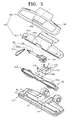
- FIG. 2 is an exploded perspective view showing the brush assembly of FIG 1;
- FIG. 3A is a front view showing a turbine of FIG. 2;
- FIG. 3B is a side view showing the turbine of FIG. 2;
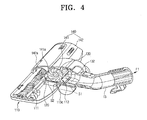
- FIG. 4 is a partial cutaway view of the brush assembly and an extension pipe, taken along line IV-IV of FIG. 1;
- FIG. 5 is a partial cutaway view of the brush assembly and the extension pipe, taken along line V-V of FIG. 1.
- FIG 1 is a perspective view showing a vacuum cleaner 10 employing a brush assembly 100 according to an embodiment of the present invention.
- the vacuum cleaner 10 comprises a cleaner body 11 in which a suction motor (not shown) and a dust-collecting chamber (not shown) are provided, the brush assembly 100 for scrubbing and hitting dirt adhered to a cleaning surface and drawing in the dirt therethrough, an extension pipe 13 and a flexible hose 12 connecting the cleaner body 11 and the brush assembly 100, and a manipulation part 14 for manipulating the vacuum cleaner 10.
- the suction motor in the cleaner body 11 is driven so as to generate a suction force. Due to the suction force, dirt is drawn into the dust-collecting chamber (not shown) of the cleaner body 11 from a cleaning surface through the brush assembly 100, the extension pipe 13 and the flexible hose 12. During this process, the brush assembly 100 scrubs and hits dirt adhered to the cleaning surface, thereby removing the dirt.
- the brush assembly 100 comprises a body 110, a partition member 113, a brush drum 120, a force-transmitting member 125, a turbine 130, and a cover 140.
- the body 110 is a lower frame of the brush assembly 100 and faces a cleaning surface to draw in dirt.
- the body 110 is provided with a dirt suction port 111, through which dirt is drawn in, and a connection part 112.
- the dirt suction port 111 is a rectangular slit formed on a front end of the body 110 and having a length L1 and a width W1. Dirt is drawn into the brush assembly 100 through the dirt suction port 111 from a cleaning surface.
- connection part 112 is a rectangular passage formed on a rear side of the body 110 and having a length L2 and a width W2. A front end of the connection part 112 is connected to the dirt suction port 111 and a rear end is connected to the extension pipe 13 (see FIG. 1).
- the partition member 113 comprises a first chamber 113a and a second chamber 113b, which are partitioned from each other by a partition 113c.
- the partition member is removably mounted in the body 110. More specifically, the partition member 113 is removably mounted in the connection part 112. For this, the partition member 113 has a width W3 smaller than the width W2 of the connection part 112.
- the first chamber 113a has a rounded bottom to receive the turbine 130 and forms a turbine chamber S2 (see FIG 4) in cooperation with a first cover 141 covering the first chamber 113a.
- the second chamber 113b is a flat bottom so that the air is less likely subjected to a resistance.
- the second chamber 113b forms a suction passage S1 (see FIG 4) in cooperation with the first cover 141 covering the second chamber 113b.
- the brush drum 120 is rotatably located in the dirt suction port 111 of the body 110.
- the brush drum 120 scrubs and hits various dirt existing on a cleaning surface, thereby removing the dirt from the cleaning surface.
- bristles 120a are press-fitted or attached to a surface of the brush drum 120.
- the brush drum 120 has a first gear 120b formed on an end thereof to receive a rotational force from the turbine 130 through a belt 125b.
- the force-transmitting member 125 comprises a rotary shaft 125a and the belt 125b to transfer the rotational force from the turbine 130 to the brush drum 120.
- the rotary shaft 125a is inserted into a shaft hole 131a (see FIG 3A) of the turbine 130 and transfers the rotational force from the turbine 130 to the belt 125b.
- the rotary shaft 125a has a second gear 125aa formed on an end thereof, and the belt 125b is engaged with the second gear 125aa.
- the belt 125b transmits the rotational force of the rotary shaft 125a to the brush drum 120, and for this, the belt 125b is engaged with both the first gear 120b of the brush drum 120 and the second gear 125aa of the rotary shaft 125a.
- the second gear 125aa of the rotary shaft 125a is directly engaged with the first gear 120b of the brush drum 120 without the belt 125b to transmit the rotational force directly from the turbine 130 to the brush drum 120.
- the turbine 130 is rotatably disposed in the turbine chamber S2 (see FIG 4) and comprises a base plate 131 and blades 132.
- the base plate 131 is a circular supporting frame.
- the shaft hole 131a is defined on a center of the base plate 131 so that the rotary shaft 125a (see FIG 2) is inserted into the shaft hole 131a.
- Eleven noise reducing holes 131b perforate around the shaft hole 131a at predetermined intervals to reduce a weight of the base plate 131 and absorb noise.
- the blades 132 protrude from the base plate 131.
- eleven blades 132 are arranged on an upper surface 131c of the base plate 131 except for a center C in a radial direction.
- the center C is a space surrounded by the blades 132. That is, the blades 132 protrude from the upper surface 131c of the base plate 131 1 except for a core 131d along a circumferential direction, and the center C is formed by the arrangements of the blades 132.
- Each blade 132 has a cutting portion 132d formed by chamfering an end of the blade 132 so that the air colliding with the blades 132 is guided to the center C of the turbine 130 in the arrow direction F2.
- the blades 132 are arranged on the upper surface 131c of the base plate 131 except for the core 131d and each have the cutting portion 132d. Accordingly, when air collides with a certain blade 132, the air is guided to the center C of the turbine 130 along the cutting portion 132d in the arrow direction F2. As a result, a kinetic energy of the air is sufficiently transmitted to the next blade 132, increasing the rotational force and efficiency of the turbine 130.
- the upper cover 140 covers the body 110 to form the suction passage S1 and the turbine chamber S2.
- the cover 140 includes the first cover 141 and the second cover 142.
- the first cover 141 is connected with an upper portion of the body 110 to form the suction passage S 1 and the turbine chamber S2 in a space between the body 110 and the cover 140.
- the suction passage S 1 is formed in the brush assembly 100 to allow dirt drawn into the brush assembly 100 to flow to the extension pipe 13.
- the suction passage S 1 is formed by the aforementioned the second chamber 113b (see FIG. 2), the first cover 141 covering the upper portion of the second chamber 113b, the body 110, and the second cover 142 covering the body 110, and the suction passage S1 fluidly communicates with the extension pipe 13. According to the above construction, the dirt adhered to the cleaning surface is drawn into the extension pipe 13 through the dirt suction port 111 and the suction passage S 1 in the arrow direction F1.
- the turbine 130 is rotatably mounted in the turbine chamber S2, and the turbine chamber S2 is a space formed by the first chamber 113a (see FIG 2) of the partition member 113 and the first cover 141 covering the first chamber 113a.
- the suction passage S1 and the turbine chamber S2 are formed integrally with the body 110 without the partition 113.
- the first air suction port 141a is formed on the first cover 141 in order for air other than the air drawn into the suction passage S1 to rotate the turbine 130.
- the first air suction port 141a fluidly communicates with the turbine chamber S2 so that the air drawn in through the first air suction port 141a rotates the turbine 130. Accordingly, the turbine 130 is not subject to a rotational force generated by the air that has passed through the suction passage S1.
- the second cover 142 forms the suction passage S 1 in cooperation with the body 110.
- the second air suction port 142a is formed on an upper surface of the second cover 142 and fluidly communicates with the first air suction port 141 a.
- the second cover 142 is connected with the first cover 141 by two mounting switches 142b (see FIG. 2) disposed on opposite sides of the second cover 142.
- the first cover 141 has connection recesses 141b (see FIG 2) formed on positions corresponding to the mounting switches 142b (see FIG 2) to be connected with the mounting switches 142b (see FIG. 2).
- the second cover 142 is made of transparent material to allow a user to check the rotational state of the brush drum 120.
- dirt is drawn into the brush assembly 100 through the dirt suction port 111 in the arrow direction F1 by a suction force of a suction force source (not shown).
- the drawn-in dirt flows into the extension pipe 13 through the suction passage S1, passes through the flexible hose 12 (see FIG 1) and is collected in the dust chamber (not shown) of the cleaner body 11 (see FIG 1).
- the dirt entrained in the air flows in the arrow direction F1 and does not flow into the turbine chamber S2 since the turbine chamber S2 is partitioned from the suction passage S 1.
- the turbine 130 is rotated by the air drawn through the second air suction port 142a and the first air suction port 141 a in the arrow direction F2 by the suction force of the suction force source (not shown).
- the suction force of the suction force source not shown.
- the turbine 130 is subject to the more powerful rotational force.
- the rotational force of the turbine 130 is transmitted to the brush drum 120 through the rotary shaft 125a (see FIG 2) and the belt 125b (see FIG. 2), thereby rotating the brush drum 120.
- the bristles 120a (see FIG 2) disposed on the surface of the brush drum 120 scrub and hit the dirt adhered to the cleaning surface to remove the dirt.
- the removed dirt flows into the extension pipe 13 through the suction passage S1 in the arrow direction F1, passes through the flexible hose 12 (see FIG 1) and then is collected in the dust chamber (not shown) of the cleaner body 11 (see FIG 1).
- the brush assembly 100 according to the embodiment of the present invention has following advantages.
- the blades 132 are arranged on the upper surface 131c of the base plate 131 except for the center C of the base plate 131, when the air collides with a certain blade 132, the air is guided to the center C of the turbine 130 so that the kinetic energy of the air is transmitted to the next blade 132. Accordingly, the rotational force of the turbine 130 increases and cleaning efficiency is improved.
Landscapes
- Engineering & Computer Science (AREA)
- Theoretical Computer Science (AREA)
- Life Sciences & Earth Sciences (AREA)
- General Physics & Mathematics (AREA)
- Physics & Mathematics (AREA)
- General Engineering & Computer Science (AREA)
- Environmental Sciences (AREA)
- Mechanical Engineering (AREA)
- Human Computer Interaction (AREA)
- Marine Sciences & Fisheries (AREA)
- Animal Husbandry (AREA)
- Biodiversity & Conservation Biology (AREA)
- Nozzles For Electric Vacuum Cleaners (AREA)
Abstract
Description
- The present invention relates to a brush assembly for a vacuum cleaner.
- In general, a brush assembly for a vacuum cleaner rotates a brush drum in contact with a cleaning surface, removes dirt from the cleaning surface by scrubbing and hitting, and draws in the dirt.
- There are suggested two methods to rotate the brush drum of the brush assembly. One is that a driving motor is provided in the brush assembly to rotate the brush drum. The other is that the brush drum is rotated by a kinetic energy of drawn-in air.
- Currently, the method of using the kinetic energy of air is preferred because the installing of the driving motor results in a complicated structure of the brush assembly and an increased cost. One example thereof is disclosed in U.S. Patent No. 5,701,633.
- In detail, a turbine is provided in a suction passage. Air that is drawn into a brush assembly rotates the turbine and a brush drum connected to the turbine such that the brush drum removes dirt from a cleaning surface by scrubbing and hitting.
- However, since the turbine is exposed to the dirt-laden air in the suction passage, big-sized dirt or large amount of dirt may clog the turbine. In this case, the turbine is not smoothly rotated, and in the worse case, the suction passage may be also clogged. Therefore, cleaning efficiency deteriorates. This becomes more problematic when a pet brush is used to groom hair of pets.
- Also, since a blade is formed from a center of the turbine, there is no gap between the center of the turbine and the blade so that the air is not able to be guided to the center. When air collides with the blade, the air is not guided to the center but is scattered. As a result, a kinetic energy of the air is not sufficiently transmitted to the next blade, which causes a low rotational force of the turbine.
- The present invention has been developed in order to solve the above problems in the related art. Accordingly, an aspect of the present invention is to provide a brush assembly capable -of preventing a turbine from being clogged by dirt regardless of the size or amount of dirt.
- Another aspect of the present invention is to provide a brush assembly capable of sufficiently transmitting a kinetic energy of air to a turbine.
- The above aspects are achieved by providing a brush assembly comprisinga body having a dirt suction port formed thereon, a cover connected with an upper portion of the body to form a suction passage and a turbine chamber, a turbine mounted in the turbine chamber, and a brush drum being rotated by a rotational force received from the turbine. The turbine chamber and the suction passage are partitioned from each other, and the turbine is rotated by an air drawn in through an air suction port, which is separated from the dirt suction port. The air suction port may be formed on the cover to prevent a dirt from being drawn therethrough. Since the turbine is rotated by the air drawn in through the air suction port, which is separated from the dirt suction port, the turbine is prevented from being clogged by dirt, dust or hair.
- The cover may comprise a first cover and a second cover, and the air suction port comprises a first air suction port formed on the first cover and a second air suction port formed on the second cover. The second cover may be made of transparent material to allow a user to check an inside of the second cover.
- The brush assembly may further comprise a partition member for forming the suction passage and the turbine chamber.
- The partition member may be removably mounted in the body. Accordingly, easy cleaning of the partition member is achieved.
- The turbine may comprise a base plate; and a plurality of blades protruding from the base plate. The blades are arranged on an upper surface of the base plate except for a center of the base plate in a radial direction. Each blade may have a cutting portion formed on a side thereof to guide the air colliding with the blade to the center. Accordingly, a kinetic energy of the drawn-in air is effectively transmitted to the turbine.
- The above aspects and other advantages of the present invention become apparent by describing an embodiment of the present invention with reference to the accompanying drawings, in which:
- FIG 1 is a perspective view showing a vacuum cleaner employing a brush assembly according to an embodiment of the present invention;
- FIG. 2 is an exploded perspective view showing the brush assembly of FIG 1;
- FIG. 3A is a front view showing a turbine of FIG. 2;
- FIG. 3B is a side view showing the turbine of FIG. 2;
- FIG. 4 is a partial cutaway view of the brush assembly and an extension pipe, taken along line IV-IV of FIG. 1; and
- FIG. 5 is a partial cutaway view of the brush assembly and the extension pipe, taken along line V-V of FIG. 1.
- In the drawings, it should be understood that like reference numerals refer to like features and structures.
- Hereinafter, an embodiment of the present invention will now be described in greater detail with reference to the accompanying drawings.
- FIG 1 is a perspective view showing a
vacuum cleaner 10 employing abrush assembly 100 according to an embodiment of the present invention. Referring to FIG 1, thevacuum cleaner 10 comprises acleaner body 11 in which a suction motor (not shown) and a dust-collecting chamber (not shown) are provided, thebrush assembly 100 for scrubbing and hitting dirt adhered to a cleaning surface and drawing in the dirt therethrough, anextension pipe 13 and aflexible hose 12 connecting thecleaner body 11 and thebrush assembly 100, and amanipulation part 14 for manipulating thevacuum cleaner 10. - According to the above-described construction, when a user turns on a
switch 14a of themanipulation part 14, the suction motor in thecleaner body 11 is driven so as to generate a suction force. Due to the suction force, dirt is drawn into the dust-collecting chamber (not shown) of thecleaner body 11 from a cleaning surface through thebrush assembly 100, theextension pipe 13 and theflexible hose 12. During this process, thebrush assembly 100 scrubs and hits dirt adhered to the cleaning surface, thereby removing the dirt. - Referring to FIG 2, the
brush assembly 100 comprises abody 110, apartition member 113, abrush drum 120, a force-transmittingmember 125, aturbine 130, and acover 140. - The
body 110 is a lower frame of thebrush assembly 100 and faces a cleaning surface to draw in dirt. Thebody 110 is provided with adirt suction port 111, through which dirt is drawn in, and a connection part 112. - The
dirt suction port 111 is a rectangular slit formed on a front end of thebody 110 and having a length L1 and a width W1. Dirt is drawn into thebrush assembly 100 through thedirt suction port 111 from a cleaning surface. - The connection part 112 is a rectangular passage formed on a rear side of the
body 110 and having a length L2 and a width W2. A front end of the connection part 112 is connected to thedirt suction port 111 and a rear end is connected to the extension pipe 13 (see FIG. 1). - The
partition member 113 comprises afirst chamber 113a and asecond chamber 113b, which are partitioned from each other by apartition 113c. The partition member is removably mounted in thebody 110. More specifically, thepartition member 113 is removably mounted in the connection part 112. For this, thepartition member 113 has a width W3 smaller than the width W2 of the connection part 112. - The
first chamber 113a has a rounded bottom to receive theturbine 130 and forms a turbine chamber S2 (see FIG 4) in cooperation with afirst cover 141 covering thefirst chamber 113a. - The
second chamber 113b is a flat bottom so that the air is less likely subjected to a resistance. Thesecond chamber 113b forms a suction passage S1 (see FIG 4) in cooperation with thefirst cover 141 covering thesecond chamber 113b. - Since the turbine chamber S2 (see FIG. 4) and the suction passage S1 (see FIG 4) are partitioned from each other by the
partition 113c, air that has been drawn in through a secondair suction port 142a and a firstair suction port 141a passes through the turbine chamber S2 (see FIG 4) in an arrow direction F2, whereas dirt-entrained air that has been drawn in through thedirt suction port 111 passes through the suction passage S1 (see FIG 4) in an arrow direction F1. Accordingly, the dirt-entrained air does not flow into the turbine chamber S2 (see FIG 4) and thus, theturbine 130 is prevented from being clogged by dirt. - The
brush drum 120 is rotatably located in thedirt suction port 111 of thebody 110. Thebrush drum 120 scrubs and hits various dirt existing on a cleaning surface, thereby removing the dirt from the cleaning surface. For this, bristles 120a are press-fitted or attached to a surface of thebrush drum 120. Thebrush drum 120 has afirst gear 120b formed on an end thereof to receive a rotational force from theturbine 130 through abelt 125b. - The force-transmitting
member 125 comprises arotary shaft 125a and thebelt 125b to transfer the rotational force from theturbine 130 to thebrush drum 120. - The
rotary shaft 125a is inserted into ashaft hole 131a (see FIG 3A) of theturbine 130 and transfers the rotational force from theturbine 130 to thebelt 125b. For this, therotary shaft 125a has a second gear 125aa formed on an end thereof, and thebelt 125b is engaged with the second gear 125aa. - The
belt 125b transmits the rotational force of therotary shaft 125a to thebrush drum 120, and for this, thebelt 125b is engaged with both thefirst gear 120b of thebrush drum 120 and the second gear 125aa of therotary shaft 125a. Alternatively, the second gear 125aa of therotary shaft 125a is directly engaged with thefirst gear 120b of thebrush drum 120 without thebelt 125b to transmit the rotational force directly from theturbine 130 to thebrush drum 120. - Referring to FIGS. 3A and 3B, the
turbine 130 is rotatably disposed in the turbine chamber S2 (see FIG 4) and comprises abase plate 131 andblades 132. - The
base plate 131 is a circular supporting frame. Theshaft hole 131a is defined on a center of thebase plate 131 so that therotary shaft 125a (see FIG 2) is inserted into theshaft hole 131a. Elevennoise reducing holes 131b perforate around theshaft hole 131a at predetermined intervals to reduce a weight of thebase plate 131 and absorb noise. - The
blades 132 protrude from thebase plate 131. In this embodiment, elevenblades 132 are arranged on anupper surface 131c of thebase plate 131 except for a center C in a radial direction. The center C is a space surrounded by theblades 132. That is, theblades 132 protrude from theupper surface 131c of thebase plate 131 1 except for acore 131d along a circumferential direction, and the center C is formed by the arrangements of theblades 132. - Each
blade 132 has a cuttingportion 132d formed by chamfering an end of theblade 132 so that the air colliding with theblades 132 is guided to the center C of theturbine 130 in the arrow direction F2. - The
blades 132 are arranged on theupper surface 131c of thebase plate 131 except for thecore 131d and each have the cuttingportion 132d. Accordingly, when air collides with acertain blade 132, the air is guided to the center C of theturbine 130 along the cuttingportion 132d in the arrow direction F2. As a result, a kinetic energy of the air is sufficiently transmitted to thenext blade 132, increasing the rotational force and efficiency of theturbine 130. - Referring to FIG 4, the
upper cover 140 covers thebody 110 to form the suction passage S1 and the turbine chamber S2. For this, thecover 140 includes thefirst cover 141 and thesecond cover 142. - The
first cover 141 is connected with an upper portion of thebody 110 to form the suction passage S 1 and the turbine chamber S2 in a space between thebody 110 and thecover 140. - The suction passage S 1 is formed in the
brush assembly 100 to allow dirt drawn into thebrush assembly 100 to flow to theextension pipe 13. - The suction passage S 1 is formed by the aforementioned the
second chamber 113b (see FIG. 2), thefirst cover 141 covering the upper portion of thesecond chamber 113b, thebody 110, and thesecond cover 142 covering thebody 110, and the suction passage S1 fluidly communicates with theextension pipe 13. According to the above construction, the dirt adhered to the cleaning surface is drawn into theextension pipe 13 through thedirt suction port 111 and the suction passage S 1 in the arrow direction F1. - The
turbine 130 is rotatably mounted in the turbine chamber S2, and the turbine chamber S2 is a space formed by thefirst chamber 113a (see FIG 2) of thepartition member 113 and thefirst cover 141 covering thefirst chamber 113a. - Alternatively, the suction passage S1 and the turbine chamber S2 are formed integrally with the
body 110 without thepartition 113. However, it is preferable to form the suction passage S1 and the turbine chamber S2 by using thepartition 113 fabricated separately like in the above-described embodiment for the purpose of easy assembly and maintenance. - The first
air suction port 141a is formed on thefirst cover 141 in order for air other than the air drawn into the suction passage S1 to rotate theturbine 130. The firstair suction port 141a fluidly communicates with the turbine chamber S2 so that the air drawn in through the firstair suction port 141a rotates theturbine 130. Accordingly, theturbine 130 is not subject to a rotational force generated by the air that has passed through the suction passage S1. - The
second cover 142 forms the suction passage S 1 in cooperation with thebody 110. The secondair suction port 142a is formed on an upper surface of thesecond cover 142 and fluidly communicates with the firstair suction port 141 a. - The
second cover 142 is connected with thefirst cover 141 by two mountingswitches 142b (see FIG. 2) disposed on opposite sides of thesecond cover 142. Thefirst cover 141 has connection recesses 141b (see FIG 2) formed on positions corresponding to the mountingswitches 142b (see FIG 2) to be connected with the mountingswitches 142b (see FIG. 2). Thesecond cover 142 is made of transparent material to allow a user to check the rotational state of thebrush drum 120. - Hereinafter, the operation of the
brush assembly 100 as constructed above will now be described. - Referring to FIG. 4, dirt is drawn into the
brush assembly 100 through thedirt suction port 111 in the arrow direction F1 by a suction force of a suction force source (not shown). The drawn-in dirt flows into theextension pipe 13 through the suction passage S1, passes through the flexible hose 12 (see FIG 1) and is collected in the dust chamber (not shown) of the cleaner body 11 (see FIG 1). The dirt entrained in the air flows in the arrow direction F1 and does not flow into the turbine chamber S2 since the turbine chamber S2 is partitioned from the suction passage S 1. - Referring to FIG. 5, the
turbine 130 is rotated by the air drawn through the secondair suction port 142a and the firstair suction port 141 a in the arrow direction F2 by the suction force of the suction force source (not shown). When drawn-in air collides with acertain blade 132, the air is guided to the center C (see FIG 3B) along the cuttingportion 131a (see FIG 3B), and then collides with thenext blade 132. Consequently, theturbine 130 is subject to the more powerful rotational force. - The rotational force of the
turbine 130 is transmitted to thebrush drum 120 through therotary shaft 125a (see FIG 2) and thebelt 125b (see FIG. 2), thereby rotating thebrush drum 120. Thebristles 120a (see FIG 2) disposed on the surface of thebrush drum 120 scrub and hit the dirt adhered to the cleaning surface to remove the dirt. Referring to FIG 4, the removed dirt flows into theextension pipe 13 through the suction passage S1 in the arrow direction F1, passes through the flexible hose 12 (see FIG 1) and then is collected in the dust chamber (not shown) of the cleaner body 11 (see FIG 1). - The
brush assembly 100 according to the embodiment of the present invention has following advantages. - First, since the turbine chamber S2 is partitioned from the suction passage S1, the dirt flows through the suction passage S 1 and does not flow into the turbine chamber S2. Therefore, the dirt does not clog the
turbine 130 mounted in the turbine chamber S2 and thus, theturbine 130 is smoothly rotated and cleaning efficiency is improved. - Second, since the
blades 132 are arranged on theupper surface 131c of thebase plate 131 except for the center C of thebase plate 131, when the air collides with acertain blade 132, the air is guided to the center C of theturbine 130 so that the kinetic energy of the air is transmitted to thenext blade 132. Accordingly, the rotational force of theturbine 130 increases and cleaning efficiency is improved. - The foregoing embodiments and advantages are merely exemplary and are not to be construed as limiting the present invention. The description of the present invention is intended to be illustrative, and not to limit the scope of the claims. Many alternatives, modifications, and variations will be apparent to those skilled in the art. In the claims, means-plus-function clauses are intended to cover the structures described herein as performing the recited function and not only structural equivalents but also equivalent structures.
Claims (17)
- A brush assembly (100) comprising:a body (110) having a dirt suction port (111) formed thereon;a cover (140) connected with an upper portion of the body to form a suction passage (S1) and a turbine chamber (S2) ;a turbine (130) mounted in the turbine chamber (S2) ; anda brush drum (120) being rotated by a rotational force received from the turbine,wherein the turbine chamber and the suction passage are partitioned from each other, and the turbine is rotated by an air drawn in through an air suction port (141 a, 142a) which is separated from the dirt suction port (111).
- The brush assembly as claimed in claim 1, wherein the air suction port (141a, 142a) is formed on the cover (140) to prevent a dirt from being drawn therethrough.
- The brush assembly as claimed in claim 2, wherein the cover (140) comprises a first cover (141) and a second cover (142), and the air suction port comprises a first air suction port (141a) formed on the first cover and a second air suction port (142a) formed on the second cover.
- The brush assembly as claimed in claim 3, wherein the second cover (142) is made of transparent material to allow a user to check an inside of the second cover.
- The brush assembly as claimed in claim 2, further comprising a partition member (113) for forming the suction passage (S1) and the turbine chamber (S2).
- The brush assembly as claimed in claim 5, wherein the partition member (113) is removably mounted in the body (110).
- The brush assembly as claimed in claim 1, wherein the turbine (130) comprises :a base plate (131) ; anda plurality of blades (132) protruding from the base plate, wherein the plurality of blades are arranged on an upper surface (131c) of the base plate except for a center (C) of the base plate in a radial direction.
- The brush assembly as claimed in claim 7, wherein each blade of the plurality of blades (132) has a cutting portion (132d) formed on a side thereof to guide the air colliding with each blade to the center (C).
- A brush assembly comprising:a suction passage (S1) for dirt-entrained air ;a turbine chamber (S2) for clean air ;a brush drum (120) in fluid communication with said suction passage (S1) ;a turbine (130) mounted in the turbine chamber so that said clean air generates a rotational force on said turbine without exposing said turbine to said dirt-entrained air; anda force-transmitting member (125) for transmitting said rotational force from said turbine (130) to said brush drum (120).
- The brush assembly as claimed in claim 9, wherein said turbine (130) comprises a base plate (131) and a plurality of blades (132) protruding from said base plate, wherein said plurality of blades are arranged on an upper surface (131c) of said base plate except for a center (C) of said base plate in a radial direction.
- The brush assembly as claimed in claim 9, wherein said force-transmitting member (125) comprises a first gear (120b) disposed on said brush drum (120), a shaft (125a) depending from said turbine (130), and a second gear (125aa) disposed on said shaft.
- The brush assembly as claimed in claim 11, further comprising a belt (125b) engaged with said first and second gears (120b, 125aa).
- The brush assembly as claimed in claim 11, wherein said first and second gears are engaged to one another.
- A brush assembly comprising:a body (110) having a dirt suction port (111) for dirt-laden air;a cover (140) having an air suction port (141a, 141b) for clean air, said cover being removably connected to said body to define a space (S1, S2) therebetween ;a partition member (113) removably mounted in said space to defme a first chamber (113a) and a second chamber (113b), said first and second chambers being partitioned from one another so that said dirt-laden air passes through said second chamber (113b) while said clean air passes through said first chamber (113a) ;a turbine (130) mounted in said first chamber (113a) so that said clean air rotates said turbine ;a brush drum (120) rotatably located in said dirt suction port (111) ; anda force-transmitting member (125) for transmitting rotation of said turbine (130) to said brush drum (120).
- The brush assembly as claimed in claim 14, wherein said force-transmitting member (125) comprises a first gear (120b) disposed on said brush drum (120), a shaft (125a) depending from said turbine (130), and a second gear (125aa) disposed on said shaft.
- The brush assembly as claimed in claim 15, further comprising a belt engaged with said first and second gears (120b, 125aa).
- The brush assembly as claimed in claim 15, wherein said first and second gears are engaged to one another.
Applications Claiming Priority (1)
| Application Number | Priority Date | Filing Date | Title |
|---|---|---|---|
| KR1020050015074A KR100656958B1 (en) | 2005-02-23 | 2005-02-23 | Brush assembly for vacuum cleaner |
Publications (2)
| Publication Number | Publication Date |
|---|---|
| EP1695651A2 true EP1695651A2 (en) | 2006-08-30 |
| EP1695651A3 EP1695651A3 (en) | 2008-01-23 |
Family
ID=35462619
Family Applications (1)
| Application Number | Title | Priority Date | Filing Date |
|---|---|---|---|
| EP05356172A Withdrawn EP1695651A3 (en) | 2005-02-23 | 2005-09-26 | A brush assembly for a vacuum cleaner |
Country Status (5)
| Country | Link |
|---|---|
| US (1) | US20060185119A1 (en) |
| EP (1) | EP1695651A3 (en) |
| JP (1) | JP2006231027A (en) |
| KR (1) | KR100656958B1 (en) |
| RU (1) | RU2308213C2 (en) |
Cited By (5)
| Publication number | Priority date | Publication date | Assignee | Title |
|---|---|---|---|---|
| CN102578965A (en) * | 2011-01-14 | 2012-07-18 | 泰怡凯电器(苏州)有限公司 | Vacuum cleaner and suction nozzle thereof |
| EP3045097A1 (en) * | 2015-01-15 | 2016-07-20 | Vorwerk & Co. Interholding GmbH | Carpet brush device |
| CN106031607A (en) * | 2015-03-20 | 2016-10-19 | 天佑电器(苏州)有限公司 | Floor brush assembly |
| WO2017117898A1 (en) * | 2016-01-04 | 2017-07-13 | 江苏美的清洁电器股份有限公司 | Floor brush for vacuum cleaner and vacuum cleaner having same |
| CN106102535B (en) * | 2014-03-19 | 2018-12-18 | 戴森技术有限公司 | Cleaning head |
Families Citing this family (5)
| Publication number | Priority date | Publication date | Assignee | Title |
|---|---|---|---|---|
| CA2684168A1 (en) * | 2009-10-30 | 2011-04-30 | G.B.D. Corp. | Surface cleaning head |
| KR102451450B1 (en) * | 2015-11-16 | 2022-10-07 | 삼성전자주식회사 | Drum for cleaner and cleaner having the same |
| WO2018210278A1 (en) * | 2017-05-17 | 2018-11-22 | 江苏美的清洁电器股份有限公司 | Pneumatic floor brush for vacuum cleaner, control component, air channel component, and floor brush for vacuum cleaner |
| KR102204555B1 (en) | 2019-08-30 | 2021-01-19 | 엘지전자 주식회사 | Cleaner unit having agitator |
| JP7620475B2 (en) * | 2021-03-30 | 2025-01-23 | 株式会社マキタ | Cleaning Equipment |
Family Cites Families (8)
| Publication number | Priority date | Publication date | Assignee | Title |
|---|---|---|---|---|
| FR2374007A1 (en) * | 1976-12-16 | 1978-07-13 | Olivier Ets Georges | APPLIANCE FOR CLEANING VARIOUS FLOORS BY SUCTION AND BRUSHING OR MOTORIZED THRESHING |
| US5088149A (en) * | 1990-08-06 | 1992-02-18 | Tennant Company | Vacuum powered scrub head |
| DE4105012C2 (en) * | 1991-02-19 | 1994-09-29 | Fedag Romanshorn Fa | Vacuum cleaner mouthpiece |
| DE4328001C2 (en) * | 1993-08-20 | 1997-03-20 | Dia Nielsen Gmbh | Ink tank |
| EP1120076B1 (en) * | 2000-01-28 | 2004-04-21 | New Ermes Europe S.p.A. | Device for removing dust and rubbish |
| DE10110312C1 (en) * | 2001-03-03 | 2002-10-02 | Duepro Ag Romanshorn | Suction cleaning tool with rotating brush roller |
| KR100470559B1 (en) * | 2002-05-11 | 2005-03-08 | 삼성광주전자 주식회사 | Sucking device of a vacuum cleaner |
| DE20209429U1 (en) * | 2002-06-18 | 2002-09-05 | Khayner, Roman, 19063 Schwerin | Upholstery nozzle for a vacuum cleaner |
-
2005
- 2005-02-23 KR KR1020050015074A patent/KR100656958B1/en not_active Expired - Fee Related
- 2005-06-17 JP JP2005177235A patent/JP2006231027A/en not_active Withdrawn
- 2005-08-19 US US11/207,455 patent/US20060185119A1/en not_active Abandoned
- 2005-09-26 EP EP05356172A patent/EP1695651A3/en not_active Withdrawn
- 2005-09-30 RU RU2005130312/12A patent/RU2308213C2/en not_active IP Right Cessation
Cited By (8)
| Publication number | Priority date | Publication date | Assignee | Title |
|---|---|---|---|---|
| CN102578965A (en) * | 2011-01-14 | 2012-07-18 | 泰怡凯电器(苏州)有限公司 | Vacuum cleaner and suction nozzle thereof |
| CN102578965B (en) * | 2011-01-14 | 2014-04-16 | 泰怡凯电器(苏州)有限公司 | Vacuum cleaner and suction nozzle thereof |
| CN106102535B (en) * | 2014-03-19 | 2018-12-18 | 戴森技术有限公司 | Cleaning head |
| EP3045097A1 (en) * | 2015-01-15 | 2016-07-20 | Vorwerk & Co. Interholding GmbH | Carpet brush device |
| CN105796004A (en) * | 2015-01-15 | 2016-07-27 | 沃维克股份有限公司 | Carpet brush appliance |
| CN106031607A (en) * | 2015-03-20 | 2016-10-19 | 天佑电器(苏州)有限公司 | Floor brush assembly |
| CN106031607B (en) * | 2015-03-20 | 2018-09-18 | 天佑电器(苏州)有限公司 | Ground brush assemblies |
| WO2017117898A1 (en) * | 2016-01-04 | 2017-07-13 | 江苏美的清洁电器股份有限公司 | Floor brush for vacuum cleaner and vacuum cleaner having same |
Also Published As
| Publication number | Publication date |
|---|---|
| RU2308213C2 (en) | 2007-10-20 |
| EP1695651A3 (en) | 2008-01-23 |
| KR100656958B1 (en) | 2006-12-13 |
| KR20060093938A (en) | 2006-08-28 |
| JP2006231027A (en) | 2006-09-07 |
| RU2005130312A (en) | 2007-04-10 |
| US20060185119A1 (en) | 2006-08-24 |
Similar Documents
| Publication | Publication Date | Title |
|---|---|---|
| JP4801516B2 (en) | Vacuum cleaner mouthpiece and vacuum cleaner using the mouthpiece | |
| EP2941994B1 (en) | Vacuum cleaner | |
| JP5914589B2 (en) | Vacuum cleaner head for vacuum cleaner | |
| KR100556811B1 (en) | Suction head of vacuum cleaner | |
| CN1325009C (en) | Suction brush assembly and a vacuum cleaner having the same | |
| KR20000075708A (en) | Suction port body for vacuum-cleaner and vacuum-cleaner having the same | |
| KR20080102645A (en) | Suction structure assembly and vacuum cleaner having same | |
| JP6232353B2 (en) | Vacuum cleaner suction port | |
| CN106691315B (en) | Drum for dust collector and dust collector with same | |
| US20060185119A1 (en) | Brush assembly for a vacuum cleaner | |
| JP2823013B2 (en) | Vacuum cleaner and its suction body | |
| JP4085466B2 (en) | Vacuum cleaner suction tool and vacuum cleaner | |
| CN100577079C (en) | Electric cleaner and suction mouth body | |
| JP3813811B2 (en) | Suction port and vacuum cleaner | |
| AU2005229624A1 (en) | A brush assembly for a vacuum cleaner | |
| KR100572153B1 (en) | Brush assembly and vacuum cleaner including the same | |
| JP2000107094A (en) | Vacuum cleaner suction tool and vacuum cleaner | |
| CN117442099A (en) | Rotating brush for suction mouth of electric vacuum cleaner and suction mouth of electric vacuum cleaner | |
| JP4738960B2 (en) | Vacuum cleaner floor nozzle and vacuum cleaner | |
| CN220937913U (en) | A cleaning machine | |
| CN220024920U (en) | Brush head module for cleaning machine and cleaning machine | |
| KR200306319Y1 (en) | Vacuum cleaning appointment suction head the brush is had built-in | |
| EP1712174A2 (en) | Turbine brush of vacuum cleaner | |
| KR100606796B1 (en) | Nozzle assembly for vacuum cleaner | |
| CN118542615A (en) | Brush head module for cleaning machine and cleaning machine |
Legal Events
| Date | Code | Title | Description |
|---|---|---|---|
| PUAI | Public reference made under article 153(3) epc to a published international application that has entered the european phase |
Free format text: ORIGINAL CODE: 0009012 |
|
| AK | Designated contracting states |
Kind code of ref document: A2 Designated state(s): AT BE BG CH CY CZ DE DK EE ES FI FR GB GR HU IE IS IT LI LT LU LV MC NL PL PT RO SE SI SK TR |
|
| AX | Request for extension of the european patent |
Extension state: AL BA HR MK YU |
|
| PUAL | Search report despatched |
Free format text: ORIGINAL CODE: 0009013 |
|
| AK | Designated contracting states |
Kind code of ref document: A3 Designated state(s): AT BE BG CH CY CZ DE DK EE ES FI FR GB GR HU IE IS IT LI LT LU LV MC NL PL PT RO SE SI SK TR |
|
| AX | Request for extension of the european patent |
Extension state: AL BA HR MK YU |
|
| STAA | Information on the status of an ep patent application or granted ep patent |
Free format text: STATUS: THE APPLICATION HAS BEEN WITHDRAWN |
|
| 18W | Application withdrawn |
Effective date: 20080124 |