EP1693162A2 - Hand-held power tool - Google Patents
Hand-held power tool Download PDFInfo
- Publication number
- EP1693162A2 EP1693162A2 EP06006327A EP06006327A EP1693162A2 EP 1693162 A2 EP1693162 A2 EP 1693162A2 EP 06006327 A EP06006327 A EP 06006327A EP 06006327 A EP06006327 A EP 06006327A EP 1693162 A2 EP1693162 A2 EP 1693162A2
- Authority
- EP
- European Patent Office
- Prior art keywords
- housing
- cutting tool
- tool
- motor
- handle
- Prior art date
- Legal status (The legal status is an assumption and is not a legal conclusion. Google has not performed a legal analysis and makes no representation as to the accuracy of the status listed.)
- Granted
Links
Images


Classifications
-
- B—PERFORMING OPERATIONS; TRANSPORTING
- B27—WORKING OR PRESERVING WOOD OR SIMILAR MATERIAL; NAILING OR STAPLING MACHINES IN GENERAL
- B27C—PLANING, DRILLING, MILLING, TURNING OR UNIVERSAL MACHINES FOR WOOD OR SIMILAR MATERIAL
- B27C5/00—Machines designed for producing special profiles or shaped work, e.g. by rotary cutters; Equipment therefor
- B27C5/10—Portable hand-operated wood-milling machines; Routers
-
- B—PERFORMING OPERATIONS; TRANSPORTING
- B25—HAND TOOLS; PORTABLE POWER-DRIVEN TOOLS; MANIPULATORS
- B25F—COMBINATION OR MULTI-PURPOSE TOOLS NOT OTHERWISE PROVIDED FOR; DETAILS OR COMPONENTS OF PORTABLE POWER-DRIVEN TOOLS NOT PARTICULARLY RELATED TO THE OPERATIONS PERFORMED AND NOT OTHERWISE PROVIDED FOR
- B25F5/00—Details or components of portable power-driven tools not particularly related to the operations performed and not otherwise provided for
- B25F5/008—Cooling means
-
- B—PERFORMING OPERATIONS; TRANSPORTING
- B25—HAND TOOLS; PORTABLE POWER-DRIVEN TOOLS; MANIPULATORS
- B25F—COMBINATION OR MULTI-PURPOSE TOOLS NOT OTHERWISE PROVIDED FOR; DETAILS OR COMPONENTS OF PORTABLE POWER-DRIVEN TOOLS NOT PARTICULARLY RELATED TO THE OPERATIONS PERFORMED AND NOT OTHERWISE PROVIDED FOR
- B25F5/00—Details or components of portable power-driven tools not particularly related to the operations performed and not otherwise provided for
- B25F5/02—Construction of casings, bodies or handles
- B25F5/021—Construction of casings, bodies or handles with guiding devices
-
- B—PERFORMING OPERATIONS; TRANSPORTING
- B25—HAND TOOLS; PORTABLE POWER-DRIVEN TOOLS; MANIPULATORS
- B25F—COMBINATION OR MULTI-PURPOSE TOOLS NOT OTHERWISE PROVIDED FOR; DETAILS OR COMPONENTS OF PORTABLE POWER-DRIVEN TOOLS NOT PARTICULARLY RELATED TO THE OPERATIONS PERFORMED AND NOT OTHERWISE PROVIDED FOR
- B25F5/00—Details or components of portable power-driven tools not particularly related to the operations performed and not otherwise provided for
- B25F5/02—Construction of casings, bodies or handles
- B25F5/025—Construction of casings, bodies or handles with torque reaction bars for rotary tools
- B25F5/026—Construction of casings, bodies or handles with torque reaction bars for rotary tools in the form of an auxiliary handle
-
- Y—GENERAL TAGGING OF NEW TECHNOLOGICAL DEVELOPMENTS; GENERAL TAGGING OF CROSS-SECTIONAL TECHNOLOGIES SPANNING OVER SEVERAL SECTIONS OF THE IPC; TECHNICAL SUBJECTS COVERED BY FORMER USPC CROSS-REFERENCE ART COLLECTIONS [XRACs] AND DIGESTS
- Y10—TECHNICAL SUBJECTS COVERED BY FORMER USPC
- Y10S—TECHNICAL SUBJECTS COVERED BY FORMER USPC CROSS-REFERENCE ART COLLECTIONS [XRACs] AND DIGESTS
- Y10S16/00—Miscellaneous hardware, e.g. bushing, carpet fastener, caster, door closer, panel hanger, attachable or adjunct handle, hinge, window sash balance
- Y10S16/12—Hand grips, preformed and semi-permanent
-
- Y—GENERAL TAGGING OF NEW TECHNOLOGICAL DEVELOPMENTS; GENERAL TAGGING OF CROSS-SECTIONAL TECHNOLOGIES SPANNING OVER SEVERAL SECTIONS OF THE IPC; TECHNICAL SUBJECTS COVERED BY FORMER USPC CROSS-REFERENCE ART COLLECTIONS [XRACs] AND DIGESTS
- Y10—TECHNICAL SUBJECTS COVERED BY FORMER USPC
- Y10S—TECHNICAL SUBJECTS COVERED BY FORMER USPC CROSS-REFERENCE ART COLLECTIONS [XRACs] AND DIGESTS
- Y10S16/00—Miscellaneous hardware, e.g. bushing, carpet fastener, caster, door closer, panel hanger, attachable or adjunct handle, hinge, window sash balance
- Y10S16/24—Handle fastening means
-
- Y—GENERAL TAGGING OF NEW TECHNOLOGICAL DEVELOPMENTS; GENERAL TAGGING OF CROSS-SECTIONAL TECHNOLOGIES SPANNING OVER SEVERAL SECTIONS OF THE IPC; TECHNICAL SUBJECTS COVERED BY FORMER USPC CROSS-REFERENCE ART COLLECTIONS [XRACs] AND DIGESTS
- Y10—TECHNICAL SUBJECTS COVERED BY FORMER USPC
- Y10S—TECHNICAL SUBJECTS COVERED BY FORMER USPC CROSS-REFERENCE ART COLLECTIONS [XRACs] AND DIGESTS
- Y10S29/00—Metal working
- Y10S29/082—Air current generated by cutter
-
- Y—GENERAL TAGGING OF NEW TECHNOLOGICAL DEVELOPMENTS; GENERAL TAGGING OF CROSS-SECTIONAL TECHNOLOGIES SPANNING OVER SEVERAL SECTIONS OF THE IPC; TECHNICAL SUBJECTS COVERED BY FORMER USPC CROSS-REFERENCE ART COLLECTIONS [XRACs] AND DIGESTS
- Y10—TECHNICAL SUBJECTS COVERED BY FORMER USPC
- Y10S—TECHNICAL SUBJECTS COVERED BY FORMER USPC CROSS-REFERENCE ART COLLECTIONS [XRACs] AND DIGESTS
- Y10S29/00—Metal working
- Y10S29/083—Fan coaxial with cutter
-
- Y—GENERAL TAGGING OF NEW TECHNOLOGICAL DEVELOPMENTS; GENERAL TAGGING OF CROSS-SECTIONAL TECHNOLOGIES SPANNING OVER SEVERAL SECTIONS OF THE IPC; TECHNICAL SUBJECTS COVERED BY FORMER USPC CROSS-REFERENCE ART COLLECTIONS [XRACs] AND DIGESTS
- Y10—TECHNICAL SUBJECTS COVERED BY FORMER USPC
- Y10T—TECHNICAL SUBJECTS COVERED BY FORMER US CLASSIFICATION
- Y10T403/00—Joints and connections
- Y10T403/59—Manually releaseable latch type
- Y10T403/591—Manually releaseable latch type having operating mechanism
- Y10T403/595—Lever
-
- Y—GENERAL TAGGING OF NEW TECHNOLOGICAL DEVELOPMENTS; GENERAL TAGGING OF CROSS-SECTIONAL TECHNOLOGIES SPANNING OVER SEVERAL SECTIONS OF THE IPC; TECHNICAL SUBJECTS COVERED BY FORMER USPC CROSS-REFERENCE ART COLLECTIONS [XRACs] AND DIGESTS
- Y10—TECHNICAL SUBJECTS COVERED BY FORMER USPC
- Y10T—TECHNICAL SUBJECTS COVERED BY FORMER US CLASSIFICATION
- Y10T408/00—Cutting by use of rotating axially moving tool
- Y10T408/21—Cutting by use of rotating axially moving tool with signal, indicator, illuminator or optical means
-
- Y—GENERAL TAGGING OF NEW TECHNOLOGICAL DEVELOPMENTS; GENERAL TAGGING OF CROSS-SECTIONAL TECHNOLOGIES SPANNING OVER SEVERAL SECTIONS OF THE IPC; TECHNICAL SUBJECTS COVERED BY FORMER USPC CROSS-REFERENCE ART COLLECTIONS [XRACs] AND DIGESTS
- Y10—TECHNICAL SUBJECTS COVERED BY FORMER USPC
- Y10T—TECHNICAL SUBJECTS COVERED BY FORMER US CLASSIFICATION
- Y10T408/00—Cutting by use of rotating axially moving tool
- Y10T408/65—Means to drive tool
-
- Y—GENERAL TAGGING OF NEW TECHNOLOGICAL DEVELOPMENTS; GENERAL TAGGING OF CROSS-SECTIONAL TECHNOLOGIES SPANNING OVER SEVERAL SECTIONS OF THE IPC; TECHNICAL SUBJECTS COVERED BY FORMER USPC CROSS-REFERENCE ART COLLECTIONS [XRACs] AND DIGESTS
- Y10—TECHNICAL SUBJECTS COVERED BY FORMER USPC
- Y10T—TECHNICAL SUBJECTS COVERED BY FORMER US CLASSIFICATION
- Y10T409/00—Gear cutting, milling, or planing
- Y10T409/30—Milling
- Y10T409/303976—Milling with means to control temperature or lubricate
-
- Y—GENERAL TAGGING OF NEW TECHNOLOGICAL DEVELOPMENTS; GENERAL TAGGING OF CROSS-SECTIONAL TECHNOLOGIES SPANNING OVER SEVERAL SECTIONS OF THE IPC; TECHNICAL SUBJECTS COVERED BY FORMER USPC CROSS-REFERENCE ART COLLECTIONS [XRACs] AND DIGESTS
- Y10—TECHNICAL SUBJECTS COVERED BY FORMER USPC
- Y10T—TECHNICAL SUBJECTS COVERED BY FORMER US CLASSIFICATION
- Y10T409/00—Gear cutting, milling, or planing
- Y10T409/30—Milling
- Y10T409/304088—Milling with means to remove chip
-
- Y—GENERAL TAGGING OF NEW TECHNOLOGICAL DEVELOPMENTS; GENERAL TAGGING OF CROSS-SECTIONAL TECHNOLOGIES SPANNING OVER SEVERAL SECTIONS OF THE IPC; TECHNICAL SUBJECTS COVERED BY FORMER USPC CROSS-REFERENCE ART COLLECTIONS [XRACs] AND DIGESTS
- Y10—TECHNICAL SUBJECTS COVERED BY FORMER USPC
- Y10T—TECHNICAL SUBJECTS COVERED BY FORMER US CLASSIFICATION
- Y10T409/00—Gear cutting, milling, or planing
- Y10T409/30—Milling
- Y10T409/306216—Randomly manipulated, work supported, or work following device
- Y10T409/306552—Randomly manipulated
- Y10T409/306608—End mill [e.g., router, etc.]
-
- Y—GENERAL TAGGING OF NEW TECHNOLOGICAL DEVELOPMENTS; GENERAL TAGGING OF CROSS-SECTIONAL TECHNOLOGIES SPANNING OVER SEVERAL SECTIONS OF THE IPC; TECHNICAL SUBJECTS COVERED BY FORMER USPC CROSS-REFERENCE ART COLLECTIONS [XRACs] AND DIGESTS
- Y10—TECHNICAL SUBJECTS COVERED BY FORMER USPC
- Y10T—TECHNICAL SUBJECTS COVERED BY FORMER US CLASSIFICATION
- Y10T409/00—Gear cutting, milling, or planing
- Y10T409/30—Milling
- Y10T409/308624—Milling with limit means to aid in positioning of cutter bit or work [e.g., gauge, stop, etc.]
-
- Y—GENERAL TAGGING OF NEW TECHNOLOGICAL DEVELOPMENTS; GENERAL TAGGING OF CROSS-SECTIONAL TECHNOLOGIES SPANNING OVER SEVERAL SECTIONS OF THE IPC; TECHNICAL SUBJECTS COVERED BY FORMER USPC CROSS-REFERENCE ART COLLECTIONS [XRACs] AND DIGESTS
- Y10—TECHNICAL SUBJECTS COVERED BY FORMER USPC
- Y10T—TECHNICAL SUBJECTS COVERED BY FORMER US CLASSIFICATION
- Y10T83/00—Cutting
- Y10T83/202—With product handling means
- Y10T83/2066—By fluid current
-
- Y—GENERAL TAGGING OF NEW TECHNOLOGICAL DEVELOPMENTS; GENERAL TAGGING OF CROSS-SECTIONAL TECHNOLOGIES SPANNING OVER SEVERAL SECTIONS OF THE IPC; TECHNICAL SUBJECTS COVERED BY FORMER USPC CROSS-REFERENCE ART COLLECTIONS [XRACs] AND DIGESTS
- Y10—TECHNICAL SUBJECTS COVERED BY FORMER USPC
- Y10T—TECHNICAL SUBJECTS COVERED BY FORMER US CLASSIFICATION
- Y10T83/00—Cutting
- Y10T83/242—With means to clean work or tool
-
- Y—GENERAL TAGGING OF NEW TECHNOLOGICAL DEVELOPMENTS; GENERAL TAGGING OF CROSS-SECTIONAL TECHNOLOGIES SPANNING OVER SEVERAL SECTIONS OF THE IPC; TECHNICAL SUBJECTS COVERED BY FORMER USPC CROSS-REFERENCE ART COLLECTIONS [XRACs] AND DIGESTS
- Y10—TECHNICAL SUBJECTS COVERED BY FORMER USPC
- Y10T—TECHNICAL SUBJECTS COVERED BY FORMER US CLASSIFICATION
- Y10T83/00—Cutting
- Y10T83/667—Tool carrier or guide affixed to work during cutting
- Y10T83/68—Entirely work supported
-
- Y—GENERAL TAGGING OF NEW TECHNOLOGICAL DEVELOPMENTS; GENERAL TAGGING OF CROSS-SECTIONAL TECHNOLOGIES SPANNING OVER SEVERAL SECTIONS OF THE IPC; TECHNICAL SUBJECTS COVERED BY FORMER USPC CROSS-REFERENCE ART COLLECTIONS [XRACs] AND DIGESTS
- Y10—TECHNICAL SUBJECTS COVERED BY FORMER USPC
- Y10T—TECHNICAL SUBJECTS COVERED BY FORMER US CLASSIFICATION
- Y10T83/00—Cutting
- Y10T83/828—With illuminating or viewing means for work
Definitions
- This invention pertains generally to hand-held power tools such as spiral cutting tools.
- a spiral cutting tool is a hand-held power tool having an electric motor that rotates a spiral cutting tool bit at high speeds.
- a spiral cutting tool bit includes a sharp cutting edge that is wrapped in a spiral around the axis of the bit.
- the spiral cutting tool bit is designed for cutting perpendicular to the axis of the bit.
- the electric motor that drives the bit is enclosed in a motor housing.
- the motor housing is generally cylindrical in shape, with the spiral cutting tool bit extending from one end of the motor housing along the axis of the housing.
- a spiral cutting tool is used to remove material from a workpiece by moving the rotating spiral cutting tool bit through the workpiece in a direction perpendicular to the axis of rotation of the bit.
- a spiral cutting tool is conventionally operated by grasping the motor housing with one or both hands, turning on the electric motor to begin high-speed rotation of the spiral cutting tool bit, plunging the spinning spiral cutting tool bit into a workpiece, such as a piece of wood, and then moving the cutting tool bit through the workpiece in a direction perpendicular to the axis of the spiral cutting tool bit by moving the motor housing in a direction parallel to the plain of the workpiece surface while keeping the axis of the motor housing generally perpendicular to the workpiece surface.
- Precise control of a cut being made by a spiral cutting tool, or any other hand-held power tool is dependent upon at least two factors: the tool operator maintaining a firm grasp on the tool, and good visibility of the workpiece at the point of the cut.
- the handle may be attached securely to the spiral cutting tool when the tool is to be used for extended periods of time, or generally to enhance the operator's comfort and control in using the spiral cutting tool.
- the handle may be removed from the tool, for example, when the spiral cutting tool is to be used in tight quarters wherein the handle might become an obstacle to precise control of the spiral cutting tool.
- the handle is removably secured to the spiral cutting tool by threaded knobs that are inserted through mounting holes in the ends of the handle and tightly threaded into threaded holes formed in handle lugs extending from the motor housing.
- the threaded knobs are preferably designed so that the detachable handle may be secured tightly to the handle lugs by hand, without the need for a wrench or other tool.
- the detachable handle also features compartments formed therein for holding various spiral cutting tool accessories, such as extra spiral cutting tool bits and a wrench for securing the bits to the spiral cutting tool.
- Many hand-held power tools include a power on/off switch mounted on the tool motor housing, rather than on a tool handle.
- the tool motor cannot be controlled by the hand, usually the dominant hand, which is grasping the tool by the handle.
- Some hand-held power tools therefore, have power on/off trigger switches mounted in or near the tool handle.
- such handles are not removable.
- such trigger switches are typically mounted in the handle of the power tool such that the trigger switch is operated by the forefinger, or forefinger and index finger, of the operator's hand. These are typically the strongest fingers of the hand, which must be used, therefore, in such tools, to both hold and control the tool while simultaneously operating the trigger switch. This can increase fatigue and reduce the operator's effective control of the tool.
- the second significant factor in making a precise cut using a spiral cutting tool, or any other hand-held power tool is operator visibility at the point of the cut.
- Such visibility can be reduced by a build-up of cutting debris, e.g., sawdust, removed from the workpiece by the tool at the point of a the cut, and poor lighting at the point of the cut.
- Some power tools employ vacuum systems connected to the tool to remove cutting debris from the point of the cut.
- the use of such a vacuum system often makes use of the tool more cumbersome.
- Proper lighting at the point of a cut can be a problem, both in generally poorly lighted construction environments and, more generally, in any environment where the operator of the tool and the tool itself cast a shadow over the workpiece at the point of the cut.
- the present invention provides an improved hand-held power tool, such as a spiral cutting tool, including features for improving an operator's ability to operate the tool to provide a precise cut.
- the present invention provides a hand-held power tool with features for improving both operator control of the tool and operator visibility at the point of a cut being made using the tool.
- the present invention provides an easily detachable handle for a spiral cutting tool and other similar hand-held power tools.
- the use of the detachable handle provides for extensive continuous use of the tool while maintaining operator comfort and tool control.
- the detachable handle of the present invention includes a gripping surface for an operator's hand which is oriented substantially parallel with the axis of the tool housing. Precise control of the tool is maintained by grasping the tool with two hands, one on the handle, the other on the tool motor housing.
- the detachable handle facilitates positioning the tool with its axis perpendicular to the workpiece, and moving the tool along the plane of the workpiece in a direction perpendicular to the axis of the tool.
- a detachable handle in accordance with the present invention is easily and quickly attachable to the motor housing of a spiral cutting tool, or other hand-held power tool, and is easily and quickly detachable therefrom:
- the detachable handle may be attached securely to the tool when the tool is to be used for extended periods of time, or generally to enhance the operator's comfort and control in using the tool, and may be removed easily and quickly from the tool, for example, when the tool is to be used in tight quarters, where the detachable handle might become an obstacle to precise control of the tool.
- a detachable handle in accordance with the present invention preferably has two handle ends, each of which is securely but detachably attachable to a hand-held power tool housing. This provides a very securely attachable and stable handle for the tool.
- the structures by which the handle is detachably attached to the tool housing preferably provide for easy and quick removal of the handle from the housing when desired.
- a detachable handle may include a fixed handle mounting structure, such as fixed tab projections, extending from one end of the handle, and a moveable handle mounting mechanism, such as a rotatable rod, extending from the other end of the handle.
- the extending tabs preferably are hook-shaped, such that the tabs may be hooked into the corresponding apertures formed in the tool housing.
- the rotatable rod preferably includes a distal radially extending portion formed at the distal end thereof, which is sized to fit through a slot formed in the corresponding aperture formed in the tool housing. The rotatable rod may be mounted in the corresponding aperture formed in the housing by rotating the rod so as to align the distal radially extending portion with the slot formed in the corresponding aperture formed in the housing.
- the rotatable rod is then rotated such that the distal radially extending portion is aligned perpendicularly to the slot, thereby preventing removal of the rod, and, therefore, the handle, from the aperture formed in the housing.
- a second radially extending portion may be formed on the rotatable rod to engage a threaded wall formed in the corresponding aperture in the tool motor housing. The second radially extending portion and threaded wall interact to pull the end of the handle tightly against the tool housing as the rod is rotated, to thereby secure the handle to the tool housing.
- the rotatable rod may preferably be rotated by a lever mechanism attached to the rod and extending from the detachable handle.
- the rotatable rod and lever are preferably mounted on the top or thumb end of the detachable handle.
- a thumb tab is preferably formed extending from the lever to facilitate movement of the lever by an operator's thumb.
- the detachable handle may, therefore, be easily and quickly attached to the tool housing by an operator by inserting the extending tabs and rotatable rod into the apertures formed in the housing and operating the lever mounted on the detachable handle to rotate the rotatable rod to secure the handle to the housing. By operating the lever mounted on the detachable handle in the opposite direction, the detachable handle is easily and quickly removed from the housing.
- a detachable handle in accordance with the present invention preferably includes one or more compartments formed therein, e.g., for holding and storing spiral cutting tool or other handle-held power tool accessories.
- the compartment may be accessible through an aperture formed in the detachable handle, which may be covered by a hinged door.
- a detachable handle for a spiral cutting tool, or other hand-held power tool preferably includes an on/off trigger switch, for activating the tool, mounted therein.
- the trigger switch is preferably mounted on an inside of the detachable handle, i.e., on the side of the handle facing the tool housing when the handle is attached to the tool.
- the trigger switch is preferably mounted at a lower end of the inside of the handle, such that the trigger switch is operable by the little finger (pinky) and ring finger of the operator's hand. This allows the stronger middle finger, index finger, and thumb of the operator's hand to be used solely for holding and controlling the tool to which the handle is attached.
- the trigger switch mounted in the detachable handle is coupled to a motor in the tool motor housing such that the motor is activated when the trigger switch is actuated and the detachable handle is mounted on the power tool housing.
- the trigger switch is preferably coupled to the tool motor via a motor controller mounted in the housing without a mechanical connection between the trigger switch and the motor controller. Such a mechanical connection between the trigger switch, mounted in the detachable handle, and the motor controller, mounted in the motor housing, might interfere with the easy and quick attachment of the detachable handle to, and removal of the detachable handle from, the tool housing.
- the trigger switch mounted in the detachable handle may be coupled to a magnet, mounted on a moveable arm mounted in the detachable handle, which is moved toward the tool housing when the trigger switch is actuated by an operator and the detachable handle is mounted on the housing.
- a Hall effect sensor or similar magnetic field sensor, is mounted within the tool housing to detect the movement or position of the magnet. The magnetic field sensor is thus employed to detect the movement of the magnet in response to the activation of the trigger switch.
- the sensor is coupled to the motor controller which activates the tool motor in response to the detection of the movement of the magnet.
- activation of the tool motor by a trigger switch mounted in a detachable handle is achieved without providing a mechanical connection between the trigger switch, mounted in the detachable handle, and the motor controller for controlling the tool motor, mounted in the tool housing, thereby providing a rugged trigger switch coupling mechanism which does not interfere with the easy and quick attachment and detachment of the detachable handle to and from the tool housing.
- a spiral cutting tool, or other hand-held power tool preferably includes a multiple-position power on/off switch mounted on the tool housing.
- the multiple-position power switch is used in combination with the trigger switch mounted in the detachable handle for controlling the power on/off state of the tool motor.
- the multiple-position power on/off switch mounted on the tool housing preferably includes at least three operating positions. In a first operating position of the multiple-position power on/off switch, the tool motor is turned off and the trigger switch is disabled. Thus, when the multiple-position power on/off switch is in this first position, the tool motor will not be activated even if the trigger switch mounted on the detachable handle attached to the tool housing is actuated.
- the trigger switch mounted in the detachable handle mounted to the tool motor housing is enabled.
- the tool motor is activated only when the trigger switch mounted in the detachable handle is actuated.
- the tool motor is activated. As long as the multiple-position power switch is in this third position, the tool motor will be in operation, whether or not the trigger switch in the detachable handle is actuated (or the detachable handle is even attached to the tool housing).
- the multiple-position power on/off switch in accordance with the present invention thus allows an operator of a spiral cutting tool, or other hand-held power tool, fully to control the power on/off state of the tool motor, including controlling when the power on/off state of the tool may be controlled by the trigger switch mounted in the detachable handle.
- a spiral cutting tool, or other hand-held power tool in accordance with the present invention preferably includes a variable speed motor.
- the operating speed of the motor may be controlled by a speed control button and user interface which allows an operator of the tool to select the operating speed of the motor, and which presents to the operator a visual indication of the speed selected.
- a hand-held power tool motor may begin operation at an initial operating speed when the tool motor is first turned on, by use of either a multiple-position power switch mounted on the tool housing or a trigger switch mounted on a detachable handle attached to the tool housing.
- a speed control button is provided on the tool housing and coupled to a motor controller. Each time the speed control button is actuated, the motor controller changes the speed of the motor in response thereto.
- the motor speed may increase or decrease one step from the then-current operating speed, until either the highest or lowest available operating speed is reached, at which point, upon the next actuation of the speed control button, the motor is controlled to decrease or increase motor speed by one step. For example, if four motor operating speeds are made available, the motor speed may be increased or decreased by three steps from the initial motor operating speed, by one step each time the motor speed control button is actuated. Upon the fourth actuation of the motor speed control button, if the motor speed is at its lowest setting, the motor will be controlled to increase the motor speed to the next higher speed. If the motor speed is at its highest setting, the motor will be controlled to decrease the motor speed to the next lower speed.
- the motor may be controlled to return to its initial operating speed upon the next actuation of the speed control button after either the highest or lowest operating speed is reached.) the motor speed will return to the initial operating speed.
- a single button is employed to cycle the tool motor through the available operating speeds.
- Motor speed indicator LEDs may be mounted on the spiral cutting tool housing near the motor speed control button, and illuminated by the motor controller to indicate to the operator of the tool the current motor speed selected.
- the speed control button and LEDs are preferably covered by a single piece of flexible plastic, which protects the speed control interface from cutting debris, while allowing the speed control button to be operated therethrough and the speed indication LEDs to be visible therethrough.
- a spiral cutting tool, or other hand-held power tool, in accordance with the present invention preferably also provides for improved visibility of a workpiece at the point of a cut being made by the tool. Improved visibility under poor lighting conditions is provided by one or more high-output LEDs mounted in the tool housing near a position where the tool's motor shaft emerges from the housing, so as to direct a beam or beams of light toward a workpiece at the point of a cut being made by the tool.
- the LEDs may be mounted in aperture pockets or receptacles formed in the tool motor housing near the point where the tool motor shaft emerges from the tool. Multiple LEDs may be mounted in the tool housing at angles so as to provide beams of light which cross each other at the area of a cut.
- At least two such high-output LEDs may be provided, which may be mounted on opposite sides of a tool motor shaft, in the tool housing, and at angles such that the beams provided by the high-output LEDs cross each other at a point which intersects with the axis of the tool motor shaft at a position in front of the tool motor shaft at which, e.g., a spiral cutting tool bit is to be mounted and at a point where the spiral cutting tool bit is cut into a workpiece.
- the LEDs may be controlled to turn on whenever the power switch is activated.
- a spiral cutting tool, or other hand-held power tool preferably includes a fan located within the motor housing and preferably attached to the motor shaft. When the motor is turned on, the fan is rotated at a high speed to draw air through the motor housing and across the tool motor to thereby cool the motor.
- One or more air exhaust vents may be formed in the motor housing at the end of the motor housing adjacent to the point where the motor shaft emerges from the motor housing, i.e., at the end of the shaft where a spiral cutting tool bit or other attachment is attached to the motor shaft. Air drawn through the motor housing by the fan is directed through the air vents onto the workpiece surface at the point of the cut, thereby blowing cutting debris away from the point of the cut, to enhance visibility thereof.
- a moveable air vent cover is provided.
- the moveable air vent cover is preferably mounted in the tool motor housing, and may be operated to close the vents in the motor housing which open toward the workpiece.
- the moveable air vent cover may also be formed to open other vents formed in the motor housing directed radially outward from the sides of the motor housing when the air vents directed toward the workpiece are closed. Air drawn through the motor housing to cool the motor may thereby be redirected in a direction radial to the tool, using the moveable air vent cover, so as to not disturb cutting debris from a workpiece being cut.
- the air vent cover may be implemented as a flat ring having vertically extending portions formed along an outer edge thereof.
- the flat ring includes apertures formed therein which may be aligned with the air vents formed in the end of the tool housing to allow exhaust air to be directed toward a workpiece being cut.
- the vertically extending portions are formed on the ring such that, when the ring is positioned such that the apertures formed therein are aligned with the air vents to allow air flow to be directed toward the workpiece, the vertically extending portions at least partially block the flow of air through other air vents formed in a sidewall of the tool housing.
- the air vent cover is preferably mounted in the tool housing for rotational movement therein, and may include a tab, lever, handle, or other structure attached thereto which extends from the housing, e.g., through a slot in the sidewall of the motor housing. Using this tab, the air vent cover may be rotated in the motor housing by an operator between positions allowing air flow through the air vents to be directed toward a workpiece, and blocking air flow toward the workpiece. Thus, an operator may direct a flow of air toward a workpiece to blow cutting debris therefrom, to enhance visibility of the workpiece surface at the point of a cut, or block such air flow, when desired.
- the present invention thus provides a spiral cutting tool, or other hand-held power tool, having features which enhance the utility of the tool by providing for enhanced control and operation of the tool during use, and visibility of a workpiece being cut by the tool.
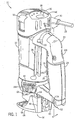
- the spiral cutting tool 20 includes a motor housing 22 to which a detachable handle 24 is attached.
- the motor housing 22 is preferably made of an electrically insulating material, such as hard plastic.
- the motor housing 22 is generally cylindrical in shape, and may include raised gripping surfaces 26 formed thereon that allow a firm grip on the cutting tool 20 to be maintained when the cutting tool 20 is grasped around the motor housing 22.
- the motor housing 22 may be formed as two or more molded pieces which are joined together to form the housing 22 in a conventional manner, such as using fasteners, an adhesive, welding, or a combination thereof.
- An electric motor (not visible in Figs. 1 and 2) is enclosed within the motor housing 22.
- the motor receives electrical power through an electrical cord 28 (only a portion of which is shown in Figs. 1 and 2).
- the electrical cord 28 may preferably include a rubber cover that stays flexible in cold operating environments.
- a thick rubber connecting sleeve 30 is preferably provided where the electrical cord 28 is joined to the motor housing 22. This connecting sleeve 30 provides strain relief at the end of the electrical cord 28 to prevent crimping, cracking, and excessive wear of the cord 28 where it is joined to the cutting tool 20.
- the connecting sleeve 30 is preferably made of a thicker or less pliable material than the rubber coating covering the electrical cord 28. As illustrated in Figs.
- the connecting sleeve 30 preferably extends from a side of the motor housing 22 displaced radially from the position of the detachable handle 24 on the motor housing 22 by approximately 90°.
- the connecting sleeve 30 is bent or shaped to turn from the position where it is attached to the motor housing 22 in the direction of the position of the detachable handle 24 on the motor housing 22.
- the end of the electrical cord 28 which is connected by the connecting sleeve 30 to the tool 20 is positioned by the connecting sleeve 30 on the tool 20 such that the electrical cord 28 extends from the motor housing 22 in a direction toward an operator of the spiral cutting tool 20 holding the tool 20 by the detachable handle 24, but is displaced from the position of the handle 24.
- This positioning of the electrical cord 28 helps assure that the electrical cord 18 will not interfere with operation of the spiral cutting tool 22 as the tool 22 is used, e.g., to cut a workpiece.
- the electric motor is turned on and off by a power on/off switch 32 mounted on the motor housing 22.
- the power on/off switch 32 is preferably a multiple-position on/off switch.
- the electric motor may also be turned on and off by a trigger switch 34 mounted on the detachable handle 24.
- operation of the trigger switch 34 mounted in the detachable handle 24 to turn the electric motor on and off may be enabled by operation of the multiple position on/off power switch 32.
- the electric motor is preferably capable of operation at multiple speeds.
- a motor speed control button 36 may be provided on the motor housing 22 for controlling the operating speed of the tool motor.
- the motor speed control button 36 may be implemented as a push button switch which changes the speed of the motor each time the switch 36 is depressed.
- Motor speed indicators such as indicator LEDs 38, may be mounted on the motor housing 22 near the motor speed control switch 36 to indicate to an operator of the tool 20 the operating speed of the tool motor.
- the motor speed control switch 36 and motor speed indicators 38 may be covered, e.g., by a thin and flexible piece of plastic 40, attached to the motor housing 22 in a conventional manner, which prevents dust or other debris from entering the motor housing 22 and damaging or affecting operation of the switch 36, indicators 38, or other components within the motor housing 22.
- a spiral cutting tool 20 in accordance with the present invention may have an electric motor capable of being operated at four speeds.
- the motor When the motor is first turned on, e.g., using the multiple-position on/off switch 32, or the trigger switch 34, the motor begins operation at an initial preselected speed, e.g., a no-load rotation speed of 15,000 RPM.
- an initial preselected speed e.g., a no-load rotation speed of 15,000 RPM.
- the motor speed may change from the initial 15,000 RPM to 20,000 RPM the first time the button 36 is actuated, from 20,000 RPM to 25,000 RPM the second time the button 36 is actuated, and from 25,000 RPM to 30,000 RPM the third time the button is actuated.
- the motor speed control button 36 is actuated the fourth time, with the motor on and running, the motor speed preferably decreases by one step, e.g., back to 25,000 RPM.
- more or fewer than four motor speeds may be provided, different motor speeds may be provided, and different increments between available motor speeds may be provided in accordance with the present invention.
- the motor speed may be controlled to return to its initial operating speed upon the next actuation of the speed control button after either the highest or lowest operating speed is reached.)
- Appropriate ones of the motor speed indicator LEDs 38 are illuminated each time the motor speed control button 36 is actuated to indicate the operating speed of the motor.
- the speed of the motor may be controlled in a different manner in response to actuation of the motor speed control button 36.
- the tool motor may start operation at a relatively high initial operating speed, with the speed of the motor reduced each time the motor speed control button 36 is actuated, or may start at a relatively low initial operating speed, with the speed of the motor increased each time the motor speed control button 36 is actuated.
- a microprocessor or similar digital device is employed as a motor controller, mounted in the motor housing 22, to control the ramp up and ramp down of the speed of the cutting tool motor each time the motor speed control button 36 is actuated, and to control the motor speed indicator LEDs.
- the motor controller may preferably be programmed to soft start the motor when the on/off switch 32 is actuated to turn the motor on initially. That is, the motor controller may control the motor to increase the motor speed gradually to the initial operating speed when the motor is first turned on via the on/off switch 32. (Note, however, that this soft start of the motor is preferably not employed when operation of the motor is started by actuation of the trigger switch 34, as will be described in more detail below.)
- the electric motor of the cutting tool 20 drives a motor shaft.
- a fan located within the motor housing 22, is preferably attached to the motor shaft. When the motor is turned on, by means of the multiple-position power on/off switch 32 or the trigger switch 34, the fan is rotated at a high speed to draw air through the motor housing 22 and across the electric motor, to thereby cool the motor.
- intake air vents 41 and exhaust air vents are preferably provided in the motor housing 22. Exhaust air vents are preferably formed in the end 42 (See Fig. 10) and on the side 44 of the housing 22, at the end of the housing 22 opposite the intake air vents 41.
- Cool air is drawn by the motor fan into the motor housing 22 through the air intake vents 41 to cool the electric motor, with warm air exhausted from the motor housing 22 through the exhaust air vents 42 and 44.
- the flow of air out of the exhaust air vents 42 and 44 may be directed and controlled to remove, or to prevent the removal of, cutting debris from the point of a cut being made using the cutting tool 20.
- An end of the motor shaft extends from one end of the motor housing 22 along the axis thereof.
- Attached to the end of the motor shaft is a mechanical structure 46 for securing, e.g., a spiral cutting tool bit, or other accessory, to the motor shaft.
- a spiral cutting tool bit has a cutting edge spiraled around the axis of the bit. This cutting edge is designed such that the spiral cutting tool bit, when rotated at high speed, will cut through a workpiece in a direction perpendicular to the axis of the bit. In this cutting process, significant force is applied to the cutting tool bit perpendicular to the axis thereof.
- the collet bit attachment structure 46 includes a collet nut 48 and a collet 50 centered axially within a central aperture of the collet nut 48.
- the collet nut 48 is mounted on a threaded end of the motor shaft.
- a shank of the bit is inserted into a central aperture 51 of the collet 50.
- the collet nut 48 is then tightened, by hand and then with a wrench 52, until the bit is held securely.
- the collet 50 is compressed within the collet nut 48 between a partially closed end of the collet nut 48 and the shaft.
- the collet 50 is slotted and has tapered ends such that when the collet 50 is depressed between the collet nut 48 and the shaft, the collet is depressed radially, causing the central aperture 51 of the collet 50 to close tightly around the shank of the spiral cutting tool bit.
- the collet nut 48 is loosened, using the wrench 52, until the bit can be removed easily from the central aperture 51 of the collet 50.
- a shaft lock 54 (Fig. 10) is used to prevent rotation of the motor shaft when the collet nut 48 is being loosened and tightened.
- the shaft lock 54 includes a shaft lock pin which extends through the motor housing 22. When the shaft lock 54 is depressed, the shaft lock pin engages the motor shaft, preventing rotation of the shaft, and allowing the collet nut 48 to be loosened and tightened. When the shaft lock 54 is released, a spring (not shown) attached to the shaft lock 54 causes the shaft lock pin to become disengaged from the motor shaft, allowing free rotation thereof.
- an adjustable depth guide assembly 56 may be provided.
- the depth guide assembly 56 includes a depth guide 58, a locking mechanism 60, and a depth guide bracket 62.
- the depth guide bracket 62 is attached to the cutting tool housing 22 around the location where the motor shaft emerges from the housing 22.
- the depth guide bracket 62 may be made detachable from the housing 22.
- the depth guide bracket 62 may be attached to the housing 22 in a conventional manner.
- the depth guide bracket 62 may be formed to have a split collar structure and a cam closing mechanism 69 which is operated to close the collar tight around the end of the tool housing 22 to attach the bracket 62 thereto, and which may be operated to loosen the collar to remove the bracket 62 from the housing 22.
- the depth guide bracket 62 includes an extension 64 extending in an axial direction therefrom.
- the depth guide 58 includes a corresponding extension 66 extending in an axially direction therefrom and which is aligned and coupled with the extension portion 64 of the depth guide bracket 62.
- the two extending portions 64 and 66 may be formed such that one of the extending portions 64 includes a tongue which may be extended into a groove formed in the other extending portion 66 to join the depth guide 58 and depth guide bracket 62 together while keeping the axially extending portion 66 of the depth guide 58 aligned on the same axis with the axially extending portion 64 of the depth guide bracket 62.
- the depth of cut may be set by moving the depth guide 58 in an axial direction, by sliding the axially extending portion 66 thereof along the axially extending portion 64 of the depth guide bracket 62.
- the locking mechanism 60 is then engaged to lock the extending portions 64 and 66 together to securely fix the depth guide 58 in place.
- the locking mechanism 60 may be implemented as a cam lever 60, as shown, mounted on the extending portion 66 of the depth guide 58 and coupled to the extending portion 64 of the depth guide bracket 62 to lock the two extending portions 64 and 66 together tightly when the cam lever 60 is engaged.
- the locking mechanism may be implemented using a threaded nut or a screw for locking the extending portions 64 and 66 together tightly.
- the depth guide 58 When locked into position, the depth guide 58 provides a depth guide surface 68 which lies in a plane perpendicular to the axis of the spiral cutting tool 20.
- the main components which form the depth guide 56 may be molded of hard plastic, or made of any other suitable material.
- the detachable handle 24 of the present invention is preferably detachably attachable to the motor housing 22 of the cutting tool 20.
- the handle 24 includes a gripping surface 70, which may be contoured in shape so that the handle 24 may be grasped comfortably in the hand by an operator of the cutting tool 20.
- the handle gripping surface 70 is aligned substantially parallel with the axis of the cutting tool housing 22. (It should be understood that the term "substantially parallel”, as used in this context throughout this specification, means “more parallel than not”. Therefore, the angle of the handle gripping surface 70 with respect to the axis of the cutting tool 20 may be varied from exactly parallel by several degrees.
- the handle gripping surface 70 may be made of a semi-rigid plastic material, for improving an operator's grip on the handle 24.
- the handle 24 of the present invention allows the cutting tool 20 to be grasped more firmly and comfortably with both hands, to provide greater control of the tool 20 during operation, and thereby provides for more accurate cuts with less operator fatigue.
- the handle 24 also allows the cutting tool 20 to be grasped more firmly during motor start-up, during which the reaction torque of the tool motor can cause the tool 20 to twist.
- the handle 24 also facilitates safe use of the tool 20. It may be desirable, however, that the handle 24 be detached for some applications. For example, for making cuts in close quarters or obstructed areas, the handle 24 may become an obstruction, and actually interfere with the making of accurate cuts.
- the motor housing 22 preferably includes first 72 and second 78 fixed mounting structures formed therein for attaching the detachable handle 24 to the housing 22.
- a first aperture 72 is formed on a side of the housing 22 to which the handle 24 is to be attached near an end of the housing 22 opposite the end of the tool 20 from which the motor shaft extends.
- the first handle mounting aperture 72 preferably includes a slot aperture 74 formed therein.
- the slot aperture 74 may be formed in a metallic plate or insert 76, as illustrated in Fig. 6, mounted within the housing 22 in a conventional manner behind the first housing aperture 72.
- a sidewall of the insert 76 may be threaded to form a threaded aperture wall 77 within the first aperture 72.
- One or more second mounting apertures 78 are formed in the side of the motor housing 22 near the end of the motor housing 22 from which the motor shaft emerges from the housing. As illustrated, preferably two such second mounting apertures 78 are formed in the motor housing 22.
- the first mounting aperture 72 and the second mounting apertures 78 are preferably positioned on the motor housing 22 with respect to each other such that when the detachable handle 24 is attached to the housing 22 in the manner to be described below, the handle gripping surface 70 is aligned substantially parallel with the axis of the cutting tool housing 22.
- the detachable handle 24 is attached to the housing 22 by a fixed handle mounting structure 80 formed on a first end of the handle, to be coupled to the second fixed mounting structure 78 formed in the housing 22, and a moveable mounting mechanism 82, mounted in a second end of the handle 24, to be coupled to the first fixed mounting structure 72 formed in the housing 22.
- fixed extending handle tabs 80 may be formed at one end of the handle 24 for insertion into the corresponding second housing apertures 78
- a rotatable rod 82 may be mounted extending from the other end of the detachable handle 24 for insertion into the aperture slot 74 formed in the first housing aperture 72.
- the extending handle tabs 80 may be integrally formed as part of the handle 24, or attached thereto in a conventional manner, such as using an adhesive, etc., or may be implemented as a separate metal part attached to the handle 24.
- the tabs 80 preferably extend from one end of the handle and turn downward to form a hook-like configuration.
- the extending handle tabs 80 are preferably spaced apart on the end of the handle 24 such that the spacing between the handle tabs 80 corresponds to the spacing between the second apertures 78 formed in the housing 22.
- the hook shape of the extending handle tabs 80 allows the handle tabs 80 to be inserted into the apertures 78 in a manner such that the extending handle tabs 80 are hooked within the apertures 78 within and behind a portion of the housing 22.
- the rotatable rod 82 extends from the other end of the handle 24, i.e., the end of the handle 24 opposite the end of the handle 24 having the extending tabs 80 extending therefrom.
- the rotatable rod 82 is positioned on the handle 24 such that the rotatable rod 82 may be inserted into the first aperture 72 formed in the housing 22, to position the handle 24 on the housing 22 when the extending handle tabs 80 are positioned in the housing apertures 78.
- the rotatable rod 82 preferably includes a radially extending and flattened portion 84 formed at a distal end thereof.
- a second radially extending portion 86 is preferably formed on the rotatable rod 82 proximal to the distal radially extending portion 84.
- the rotatable rod 82 is attached to a lever mechanism 88, which extends, at least in part, outside of the detachable handle 24.
- the portion of the lever 88 extending from the removable handle 24 preferably includes an extending tab 90.
- the extending tab 90 is positioned on the lever 88, and the lever 88 is positioned on the detachable handle 24, such that the lever 88 may be operated easily by, e.g., an operator's thumb positioned adjacent to the tab 90 when the handle 24 is grasped in a normal manner by the operator for use of the cutting tool 20 to which the handle 24 is attached.
- the lever mechanism 88 and rotatable rod 82 are mounted in the end of the detachable handle 24 in a conventional manner such that the rotatable rod 82 is rotatable therein by operation of the lever 88.
- the lever mechanism 88 is rotated into an "open” position, as illustrated in Fig. 5, the radially extending and flattened distal portion 84 of the rotatable rod 82 is oriented such that the distal end 84 of the rod 82 may be inserted into the slot 74 formed in the first aperture 72 in the tool housing 22.
- the lever mechanism 88 is put into this "open” position for mounting the handle to, and removing the handle 24 from, the housing 22.
- the lever mechanism 88 When the lever mechanism 88 is rotated into a "closed” position, as illustrated in Fig. 4, the radially extending and flattened distal end 84 of the rotatable rod 82 is rotated into a position perpendicular to the orientation of the slot 74 formed in the first aperture 72 in the housing 22. In this position, the distal end 84 of the rotatable rod 82 cannot be inserted into the aperture 72, or removed therefrom, if the rod 82 has been positioned in the aperture 72. Thus, the lever mechanism 88 is operated to rotate the rotatable rod 82 into this "closed” position when the handle 24 is placed in the proper position on the housing 22, to secure the detachable handle 24 to the housing.
- the detachable handle 24 is further securely attached to the housing 22 by interaction of the second radially extending portion 86 of the rotatable rod 82 with the threaded wall 77 of the first aperture 72 formed in the housing 22. With the rotatable rod 82 extended into the aperture 72 such that the second radially extending portion 86 thereof is positioned adjacent to the threaded wall 77 of the aperture 72, as the lever 88 is operated from the open position (Fig. 5) to the closed position (Fig.
- the second radially extending portion 86 is rotated along the threading formed on the wall 77 of the aperture 72 to pull the rotatable rod 82 inward, thereby pulling the end of the handle 24 in which the rotatable rod 82 is mounted tightly against the housing 22.
- the handle 24 With the end of the handle 24 having the rotatable rod 82 extending therefrom pulled tightly against the housing 22, the handle 24 is secured tightly to the housing 22, i.e., movement of the handle 24 with respect to the housing 22 is prevented.
- the following method may, therefore, be employed to easily, quickly, and securely attach the detachable handle 24 to the tool housing 22, and to easily and quickly remove the handle 24 from the housing 22.
- the handle 24 is positioned such that the hook-shaped tabs 80 extending from one end of the handle 24 are aligned with the tab apertures 78 formed in the housing 22.
- the handle 24 is tilted backward slightly, and the ends of the hooked tabs 80 are extended into the apertures 78 such that the ends of the hooked tabs 80 are engaged within the housing 22.
- the tabs 80 hooked in the second apertures 78 the other end of the handle 24 is brought forward toward the first aperture 72 formed in the housing 22.
- With the lever 88 rotated into the open position Fig.
- the radially extending and flattened distal end 84 of the rotatable rod 82 is extended through the slot 74 formed in the aperture 72.
- the second radially extending portion 86 of the rotatable rod 82 is engaged with the threads formed in the wall 77 of the first aperture 72.
- the lever 88 is then rotated from the open position (Fig. 5) to the closed position (Fig. 4). This rotates the rotatable rod 82 such that the radially extending and flattened distal end 84 of the rod 82 is rotated into an orientation perpendicular to the slot 74 formed in the aperture 72.
- the lever 88 is rotated from the closed position (Fig. 4) to the open position (Fig. 5).
- the second radially extending portion 86 of the rotatable rod 82 is rotated in the threads formed in the wall 77 of the first housing aperture 72, in a loosening direction, thereby causing the end of the handle 24 to move slightly away from the housing 22.
- the rotation of the rod 22 also causes the radially extending and flattened distal end 84 of the rod 82 to be aligned with the slot 74 formed in the rod aperture 72, such that the rod 82 is removable from the aperture 72 by pulling the end of the handle 24 away from the tool housing 22.
- the handle 24 With the end of the handle having the rotatable rod 82 mounted therein removed from the housing 22, the handle 24 may be lifted away from the housing 22 to remove the hook-shaped extended tabs 80 from the second apertures 78 formed in the housing 22. In this manner, the detachable handle 24 is easily and quickly removed from the housing 22 using a single hand, and without need for any special tools.
- the detachable handle 24 of the present invention is preferably made of an electrically insulating material, such as hard plastic.
- the handle 24 may be formed of such a material in two complementary and symmetric halves by a conventional molding process. The two halves are then joined together to form the complete handle 24.
- the two handle halves may be joined together in a conventional manner, for example, using an adhesive.
- the two handle halves are also preferably screwed together, using screws or another type of fastener. For this purpose, screw holes 91 may be formed in the handle halves.
- the handle 24 is substantially hollow, but includes molded internal structural elements 92 which provide strength and rigidity to the handle 24.
- the internal structural elements 92 of the handle 24 give the handle 24 the strength and rigidity of a solid handle, without requiring the amount of material required to form a solid handle, and with the light weight of a substantially hollow handle. Minimizing the weight of the handle 24 in this manner helps to minimize the fatigue experienced by an operator using the tool 20 with the handle 24 in place.
- the structural elements 92 of the detachable handle 24 not only provide strength and rigidity to the handle 24, but also form hollow compartments or chambers 96 within the handle 24. Compartments formed by the structural elements 92 of the handle 24 may be positioned so as to be employed for convenient storage locations. For example, as illustrated in Fig. 6, a collet 97 and the wrench 52 for tightening the collet nut 48 may be stored conveniently in compartments 96A and 96B, respectively, formed inside the handle 24. A third compartment 96C may be provided for storage of, for example, extra spiral cutting tool bits.
- Storage compartments 96A and 96C are accessed via an aperture in the handle 24.
- a compartment door 98 may preferably be provided to cover the compartment aperture.
- the door 98 may preferably be a hinged door, which is attached via a hinge structure 99 to the detachable handle 24.
- the hinged door 98 may be opened about the hinge 99 structure to access the compartments 96A and 96C within the detachable handle 24. Ridges 100, or other gripping surfaces, may be formed on the hinged door 99 to facilitate grasping of the door 98 to open and close the door 98.
- Conventional latching tabs 102 may preferably be formed, e.g., on the inside of the door 98, to engage the inside of the detachable handle 24 to maintain the door 98 in a closed position when a tool 20 to which the handle 24 is attached is in operation.
- the other accessible handle compartment 96B preferably may be specifically designed to hold the wrench 52 within the handle 24 when it is not in use.
- An aperture in the handle 24 provides access to the wrench compartment 96B.
- the size of the compartment 96B is such that the wrench 52 is held snugly therein, to prevent it from sliding out during operation of the tool 20.
- a portion 104 of the handle 24 around the aperture to the wrench compartment 96B is reduced in width such that, when the wrench 52 is placed in the compartment 96B, the head of the wrench extends slightly from this portion 104 of the sides of the handle 24. This permits the head of the wrench 52 to be grasped to pull the wrench 52 from the compartment 96B.
- the compartments 96 in the power tool handle 24 allow power tool accessories, such as extra cutting tool bits or collets 97, to be kept conveniently at hand, and separate from other tools and accessories. It should be noted that various storage compartments of different sizes and shapes than those described may be incorporated into the handle 24. Also, various types of doors or other covers may be used to close off or access the compartments 96. Moreover, it is clear that a user may store any items he chooses within the storage compartments 96. In the embodiment described herein, however, one compartment 96B is specifically designed to hold the wrench 54.
- the detachable handle 24 includes a trigger switch 34 mounted therein for turning the spiral cutting tool motor on and off when the detachable handle 24 is attached to the spiral cutting tool motor housing 22.
- the trigger switch 34 is preferably mounted adjacent to the gripping surface 70 of the detachable handle 24 on a side of the handle 24 facing the spiral cutting tool motor housing 22 when the detachable handle 24 is attached to the housing 22.
- the trigger switch 34 is preferably positioned on the detachable handle 24 such that the trigger switch 34 is operable by the little finger (pinkie) and ring finger of the hand of an operator when an operator is grasping the handle 24 for use of the tool 20 to which the handle is attached.
- the trigger switch 34 is thus preferably positioned at a lower end of the side of the detachable handle 24 facing the tool housing 22.
- This positioning of the trigger switch 34 on the detachable handle 24 allows the operator's stronger middle finger, index finger, and thumb to be used solely for holding and controlling the tool 20 to which the handle 24 is attached.
- the grip of these stronger fingers on the handle 24 need not be loosened to turn the tool on and off, as the trigger switch 34 provides for on/off operation of the tool 20 using two weaker fingers.
- the stronger fingers of the hand are less likely to become fatigued due to continuous holding of a trigger switch in an on position during operation of the tool. (There is a tendency to grasp a tool handle too strongly, and in a very fatiguing manner, when the same fingers are used for activating a trigger switch as are used for holding and controlling the tool itself.)
- the operator of a spiral cutting tool 20 in accordance with the present invention may activate the tool motor by actuating the trigger switch 34 mounted in the detachable handle 24.
- the actuation of the trigger switch 34 mounted in the detachable handle must be communicated to a motor controller 108 mounted in the motor housing 22.
- the motor controller 108 may be implemented as any circuit for controlling activation of the tool motor.
- the motor controller 108 may be implemented using a programmable device, such as a microprocessor, using discreet analog or digital components, or even using a simple wiring scheme.
- the mechanism for coupling the trigger switch 34 in the detachable handle 24 to the motor controller 108 in the motor housing 20 does not interfere with the easy, quick and secure attachment of the detachable handle 24 to the housing 22, or the easy and quick removal of the handle 24 therefrom.
- the trigger switch 34 is coupled to the motor controller 108 without a direct mechanical connection between the trigger switch 34 in the detachable handle 24, and the motor controller 108 in the motor housing 22. (This also allows for coupling the trigger switch 34 to the motor controller 108 without providing an additional aperture in the housing 22, through which potentially damaging debris may enter the motor housing 22 when the detachable handle 24 is not attached thereto.)
- the trigger switch 34 is coupled to the motor controller 108 using a magnet 116 mounted on a moveable arm 112 which is mounted in the detachable handle 24 to be moved in response to actuation of the trigger switch 34, and a magnetic field sensor 120 (such as a hall effect sensor) mounted in the tool housing 22 and coupled to the motor controller 108 for detecting movement of the magnet 116 when the trigger switch 34 is actuated to move the moveable arm 112.
- the trigger switch 34 may be mounted in the detachable handle 24 so as to be rotatable about a pivot point 110. For example, as illustrated in Fig.
- the trigger switch 34 may be mounted in the detachable handle 24 so as to be rotatable about a point 110 located near a bottom end of the trigger switch within the detachable handle 24. At the opposite end of the trigger switch, within the detachable handle 24, the end of the trigger switch 34 is placed in contact with a first end of the moveable arm 112.
- the moveable arm 112 is preferably mounted in the detachable handle 24 so as to be rotatable about a pivot point 114 located near the center of the moveable arm 112.
- the magnet 116 is mounted in or attached to the end of the moveable arm 112, in a conventional manner, opposite the end thereof which is in contact with the trigger switch 34.
- a compression spring 118 may be mounted in the detachable handle so as to press against the end of the moveable arm 112 where the moveable arm 112 contacts the trigger switch 34.
- the compression spring 118 biases the moveable arm 112 against the end of the trigger switch 34, thereby also biasing the trigger switch 34 into an "off" position.
- the magnet 116 mounted in the moveable arm 112 is positioned at a spaced apart distance from the housing 22 of the tool 20 (when the detachable handle 24 is attached to the housing 22).
- the switch 34 When the trigger switch 34 is actuated, by an operator of the tool 20, the switch 34 is rotated about pivot point 110 and the end of the trigger switch 34 in contact with the moveable arm 112 presses the end of the moveable arm 112 against the biasing action of the compression spring 118, compressing the compression spring 118, and rotating the moveable arm 112 about pivot point 114. This moves the magnet 116 mounted in the end of the moveable arm 112 opposite the compression spring 118 forward, in closer proximity to the tool housing 22 (when the detachable handle 24 is attached to the housing 22).
- the magnetic field sensor 120 such as a Hall effect sensor, is mounted within the tool housing 22, opposite the position of the magnet 116 when the trigger switch 34 is actuated.
- the magnetic field sensor 120 may be any conventional sensor adapted to detect when the magnet 116 is moved forward into a position adjacent to the housing 22, i.e., when the magnet 116 is moved into the "on" position by an operator actuating the trigger switch 34.
- the magnetic field sensor 120 is coupled to the motor controller 108 in a conventional manner, so as to provide a signal to the motor controller 108 to turn the tool motor on when the magnet 116 is moved into the "on" position.
- spiral cutting tool housing 22 is preferably made of a dielectric material, such that the magnetic field sensor 120 may be mounted within the housing 22, and operation thereof in combination with the magnet 116 to turn the tool motor on will not be affected by the presence of a portion of the motor housing 22 between the magnet 116 and magnetic field sensor 120. Thus, there is no need to form an additional aperture in the housing 22 to couple the trigger switch 34 to the motor controller 108.
- the compression spring 118 operates to rotate the trigger switch 34 and moveable arm 112 about pivot points 110 and 114, respectively, back into the "off" position.
- the magnet 116 is moved back away from the housing 22 a sufficient distance such that the magnetic field sensor 120 no longer detects the presence of the magnet 116.
- the presence of the magnet is no longer detected by the sensor 120, it provides a signal (or ceases providing a signal) to the motor controller 108 to turn off the tool motor.
- the preferred mechanism for coupling the trigger switch 34 to the motor controller 108 in accordance with the present invention does not employ a direct mechanical connection between trigger switch 34 and the motor controller 108.
- the mechanism for coupling the trigger switch 34 in the detachable handle 24 to the motor controller 108 in the motor housing 22 therefor does not interfere with the easy and quick attachment of the detachable handle 24 to, and removal of the detachable handle 24 from, the motor housing 22.
- a spiral cutting tool 20 in accordance with the present invention preferably includes a multiple-position on/off power switch 32 mounted in the tool housing 22.
- the multiple-position on/off power switch 32 is preferably employed to both turn the tool motor on and off and to enable operation of the trigger switch 34 to turn the tool motor on and off.
- the spiral cutting tool motor is turned off, and operation of the tool motor by the trigger switch 34 is disabled.
- the multiple-position on/off switch in this first position, the tool motor cannot be turned on by actuating the trigger switch 34 mounted in the detachable handle 24 attached to the cutting tool 20.
- a second operating position of the multiple-position on/off switch 32 as illustrated in Fig. 8, the tool motor remains off, but the trigger switch 34 is enabled to turn the tool on and off.
- the tool motor may be activated by actuating the trigger switch 34 mounted in the detachable handle 24 attached to the tool 20.
- the tool motor 20 is turned off by releasing the trigger switch 34.
- a third operating position of the multiple position on/off switch as illustrated in Fig. 9, the tool motor is turned on. In this position, as in the first position, the trigger switch 34 is also disabled. In other words, when the multiple position on/off switch 32 is in the third position, the tool motor is turned on, and may not be turned off by either actuating or releasing the trigger switch 34.
- a spiral cutting tool, or other hand-held power tool, in accordance with the present invention preferably provides for improved visibility of a workpiece at the point of a cut being made by the cutting tool 20.
- improved visibility under poor lighting conditions is provided by one or more high-output LEDs 130 mounted in the tool housing 22 at the end thereof from which a motor shaft extends, to which a spiral cutting tool bit or other accessory is attached.
- one or more high-output LEDs 130 may be mounted, in a conventional manner, in LED apertures 132 formed in the end of the spiral cutting tool housing 22.
- the LEDs 130 may be implemented using commercially available high-output LEDs.
- two or more LEDs 130 are mounted in the housing 22.
- the two or more LEDs 130 are preferably mounted in the housing 22 so as to be spaced apart around the mounting structure 46 for mounting, e.g., a spiral cutting tool bit to the cutting tool motor shaft.
- the high-output LEDs 130 are preferably mounted at angles within the housing 22.
- the angles with which the LEDs 130 are mounted in the housing 22 are preferably selected such that the beams of light 134 emitted by the LEDs 130 form an overlap area 136 which is positioned at the point of a cut when the tool 20 is in operation. That is, the angles with which the LEDs 130 are mounted in the housing 22 are preferably selected so that the beam overlap area 136 corresponds, e.g., to the location where a spiral cutting tool bit mounted on the spiral cutting tool 20 enters a workpiece being cut thereby.
- the LEDs 130 mounted in the spiral cutting tool housing 22 are preferably turned on whenever the cutting tool motor is in operation.
- LEDs 130 are illustrated in the exemplary embodiment of the present invention shown in Figs. 10-12, more than two high-output LEDs 130 may be mounted in the end of the motor housing 22 to illuminate a workpiece at the point of a cut, with the plurality of LEDs 132 mounted in the housing 22 at angles to form an overlap area 136 of light beams 134 at the point of the cut.
- a spiral cutting tool 20 in accordance with the present invention preferably includes one or more air vents 42 formed in the bottom of the cutting tool housing 22 to direct a flow of air onto a workpiece being cut, to thereby blow debris, such as sawdust, therefrom, to thereby enhance visibility at the point of a cut.
- a flow of air from the air vents 42 may be provided by a fan rotated by the cutting tool motor to provide a flow of air through the cutting tool housing 22 to cool the motor within the housing 22.
- a moveable air vent cover 140 is preferably provided, which allows the air vents 42 to be opened and closed, to provide for debris removal by air flow from the air vents 42, or to prevent such debris removal, as desired.
- FIG. 12 A preferred and exemplary embodiment of a movable air vent cover 140 which may be employed is illustrated in Fig. 12.
- the exemplary air vent cover 140 is implemented as a substantially flat ring 140 which is mounted within the cutting tool motor housing 22 adjacent to the air vents 42.
- the air vent cover 140 may be implemented as a complete or partially broken ring, as illustrated in Fig. 12.
- the air vent cover 140 is mounted for rotational movement within the housing 22 in a conventional manner.
- a tab 142 is preferably formed to extend radially from the air vent cover 140.
- the tab 142 is preferably formed to extend outward through a slot 144 formed in the housing 22, when the air vent cover 140 is positioned in the housing 22.
- the air vent cover 140 has one or more air vent apertures 146 formed therein.
- the air vent apertures 146 formed in the air vent cover 140 are aligned with the air vents 42, thereby allowing air flow through the motor housing 22 to exit through the air vents 42, to clear cutting debris away from the point of a cut.
- the air vent apertures 146 may be moved out of alignment with the air vents 42 such that the air vent cover 140 blocks the flow of air through the housing 22 from exiting through the air vents 42.
- the air vents 42 may be opened and closed to provide a flow of air to remove cutting debris away from a workpiece, or to prevent such a flow of air.
- the flow of cooling air flowing through the tool housing 22 exits the housing 22 through exhaust air vents 44 formed in the side of the motor housing 22, in a direction away from the workpiece being cut.
- the exhaust air vents 44 are preferably blocked when the air vent cover 140 is positioned such that air flow out of the air vents 42 is provided.
- One or more axially extending portions 148 may be formed on the air vent cover 140 for this purpose. As illustrated in Fig. 12, the axially extending portions 148 may be formed along the edge of the air vent cover 140.
- the axially extending portions 148 extend to a sufficient height, and are positioned on the air vent cover 140, such that the axially extending portions 148 may be positioned to block a flow of air through at least some of the air exhaust vents 44 when the air vent cover 140 is rotated into a position such that the air vent apertures 146 are aligned with the air vents 42.
- the air vent cover 140 is rotated into a position such that the air vents 42 are covered by the air vent cover 140, the axially extending portions 148 no longer block the air exhaust vents 44. In this manner, air flow is redirected from the air exhaust vents 44 through the air vents 42 when the air vents 42 are opened, to increase the flow of air through the air vents 42, to remove cutting debris from a workpiece being cut.
- the present invention provides a hand-held power tool with increased power tool control and visibility. Though described in detail herein with respect to a particular type of spiral cutting tool, it should be noted that the present invention is not limited in application to any particular spiral cutting tool design. The features of the present invention may be used with other types of spiral cutting tools, or similar hand-held power tools.
Abstract
Description
- This invention pertains generally to hand-held power tools such as spiral cutting tools.
- A spiral cutting tool is a hand-held power tool having an electric motor that rotates a spiral cutting tool bit at high speeds. A spiral cutting tool bit includes a sharp cutting edge that is wrapped in a spiral around the axis of the bit. The spiral cutting tool bit is designed for cutting perpendicular to the axis of the bit. The electric motor that drives the bit is enclosed in a motor housing. The motor housing is generally cylindrical in shape, with the spiral cutting tool bit extending from one end of the motor housing along the axis of the housing. A spiral cutting tool is used to remove material from a workpiece by moving the rotating spiral cutting tool bit through the workpiece in a direction perpendicular to the axis of rotation of the bit. A spiral cutting tool is conventionally operated by grasping the motor housing with one or both hands, turning on the electric motor to begin high-speed rotation of the spiral cutting tool bit, plunging the spinning spiral cutting tool bit into a workpiece, such as a piece of wood, and then moving the cutting tool bit through the workpiece in a direction perpendicular to the axis of the spiral cutting tool bit by moving the motor housing in a direction parallel to the plain of the workpiece surface while keeping the axis of the motor housing generally perpendicular to the workpiece surface.
- Precise control of a cut being made by a spiral cutting tool, or any other hand-held power tool, is dependent upon at least two factors: the tool operator maintaining a firm grasp on the tool, and good visibility of the workpiece at the point of the cut.
- Various methods have been employed to ensure that an operator may maintain a firm grip on a hand-held power tool. With extended and continuous operation, the motor housing of a spiral cutting tool can become warm, and cutting tool vibrations may cause an operator's hands and arms to become fatigued. Extended and continuous use of a spiral cutting tool by grasping the motor housing can, therefore, become uncomfortable, reducing the ability of the operator to precisely control the cut being made. U.S. Patent No., 5,813,805 issued to Robert K. Kopras, describes a detachable handle for spiral cutting tools and other similar hand-held power tools. The detachable handle provides for extensive continuous use of the power tool while maintaining operator comfort and cutting tool control. The handle may be attached securely to the spiral cutting tool when the tool is to be used for extended periods of time, or generally to enhance the operator's comfort and control in using the spiral cutting tool. The handle may be removed from the tool, for example, when the spiral cutting tool is to be used in tight quarters wherein the handle might become an obstacle to precise control of the spiral cutting tool. The handle is removably secured to the spiral cutting tool by threaded knobs that are inserted through mounting holes in the ends of the handle and tightly threaded into threaded holes formed in handle lugs extending from the motor housing. The threaded knobs are preferably designed so that the detachable handle may be secured tightly to the handle lugs by hand, without the need for a wrench or other tool. Although the threaded knobs may be tightened and removed by hand, they can take some time to thread and unthread from the handle, thereby increasing the time required for attaching the handle to and removing the handle from the motor housing. The detachable handle also features compartments formed therein for holding various spiral cutting tool accessories, such as extra spiral cutting tool bits and a wrench for securing the bits to the spiral cutting tool.
- Many hand-held power tools include a power on/off switch mounted on the tool motor housing, rather than on a tool handle. In such tools, the tool motor cannot be controlled by the hand, usually the dominant hand, which is grasping the tool by the handle. Some hand-held power tools, therefore, have power on/off trigger switches mounted in or near the tool handle. However, such handles are not removable. Furthermore, such trigger switches are typically mounted in the handle of the power tool such that the trigger switch is operated by the forefinger, or forefinger and index finger, of the operator's hand. These are typically the strongest fingers of the hand, which must be used, therefore, in such tools, to both hold and control the tool while simultaneously operating the trigger switch. This can increase fatigue and reduce the operator's effective control of the tool.
- The second significant factor in making a precise cut using a spiral cutting tool, or any other hand-held power tool, is operator visibility at the point of the cut. Such visibility can be reduced by a build-up of cutting debris, e.g., sawdust, removed from the workpiece by the tool at the point of a the cut, and poor lighting at the point of the cut. Some power tools employ vacuum systems connected to the tool to remove cutting debris from the point of the cut. However, the use of such a vacuum system often makes use of the tool more cumbersome. Proper lighting at the point of a cut can be a problem, both in generally poorly lighted construction environments and, more generally, in any environment where the operator of the tool and the tool itself cast a shadow over the workpiece at the point of the cut.
- What is desired, therefore, is an improved spiral cutting tool, or other hand-held power tool, which includes features for improving operator control of the tool and operation visibility at the point of a cut being made using the tool.
- The present invention provides an improved hand-held power tool, such as a spiral cutting tool, including features for improving an operator's ability to operate the tool to provide a precise cut. The present invention provides a hand-held power tool with features for improving both operator control of the tool and operator visibility at the point of a cut being made using the tool.
- The present invention provides an easily detachable handle for a spiral cutting tool and other similar hand-held power tools. The use of the detachable handle provides for extensive continuous use of the tool while maintaining operator comfort and tool control. The detachable handle of the present invention includes a gripping surface for an operator's hand which is oriented substantially parallel with the axis of the tool housing. Precise control of the tool is maintained by grasping the tool with two hands, one on the handle, the other on the tool motor housing. The detachable handle facilitates positioning the tool with its axis perpendicular to the workpiece, and moving the tool along the plane of the workpiece in a direction perpendicular to the axis of the tool.
- A detachable handle in accordance with the present invention is easily and quickly attachable to the motor housing of a spiral cutting tool, or other hand-held power tool, and is easily and quickly detachable therefrom: The detachable handle may be attached securely to the tool when the tool is to be used for extended periods of time, or generally to enhance the operator's comfort and control in using the tool, and may be removed easily and quickly from the tool, for example, when the tool is to be used in tight quarters, where the detachable handle might become an obstacle to precise control of the tool.
- A detachable handle in accordance with the present invention preferably has two handle ends, each of which is securely but detachably attachable to a hand-held power tool housing. This provides a very securely attachable and stable handle for the tool. The structures by which the handle is detachably attached to the tool housing preferably provide for easy and quick removal of the handle from the housing when desired. In accordance with the present invention, a detachable handle may include a fixed handle mounting structure, such as fixed tab projections, extending from one end of the handle, and a moveable handle mounting mechanism, such as a rotatable rod, extending from the other end of the handle. Fixed housing mounting structures, such as housing apertures, are formed in the tool housing and positioned therein for receiving the extending tabs and rotatable rod which extend from the ends of the handle. The extending tabs preferably are hook-shaped, such that the tabs may be hooked into the corresponding apertures formed in the tool housing. The rotatable rod preferably includes a distal radially extending portion formed at the distal end thereof, which is sized to fit through a slot formed in the corresponding aperture formed in the tool housing. The rotatable rod may be mounted in the corresponding aperture formed in the housing by rotating the rod so as to align the distal radially extending portion with the slot formed in the corresponding aperture formed in the housing. The rotatable rod is then rotated such that the distal radially extending portion is aligned perpendicularly to the slot, thereby preventing removal of the rod, and, therefore, the handle, from the aperture formed in the housing. A second radially extending portion may be formed on the rotatable rod to engage a threaded wall formed in the corresponding aperture in the tool motor housing. The second radially extending portion and threaded wall interact to pull the end of the handle tightly against the tool housing as the rod is rotated, to thereby secure the handle to the tool housing. The rotatable rod may preferably be rotated by a lever mechanism attached to the rod and extending from the detachable handle. The rotatable rod and lever are preferably mounted on the top or thumb end of the detachable handle. A thumb tab is preferably formed extending from the lever to facilitate movement of the lever by an operator's thumb. The detachable handle may, therefore, be easily and quickly attached to the tool housing by an operator by inserting the extending tabs and rotatable rod into the apertures formed in the housing and operating the lever mounted on the detachable handle to rotate the rotatable rod to secure the handle to the housing. By operating the lever mounted on the detachable handle in the opposite direction, the detachable handle is easily and quickly removed from the housing.
- A detachable handle in accordance with the present invention preferably includes one or more compartments formed therein, e.g., for holding and storing spiral cutting tool or other handle-held power tool accessories. The compartment may be accessible through an aperture formed in the detachable handle, which may be covered by a hinged door.
- In accordance with the present invention, a detachable handle for a spiral cutting tool, or other hand-held power tool, preferably includes an on/off trigger switch, for activating the tool, mounted therein. The trigger switch is preferably mounted on an inside of the detachable handle, i.e., on the side of the handle facing the tool housing when the handle is attached to the tool. The trigger switch is preferably mounted at a lower end of the inside of the handle, such that the trigger switch is operable by the little finger (pinky) and ring finger of the operator's hand. This allows the stronger middle finger, index finger, and thumb of the operator's hand to be used solely for holding and controlling the tool to which the handle is attached.
- The trigger switch mounted in the detachable handle is coupled to a motor in the tool motor housing such that the motor is activated when the trigger switch is actuated and the detachable handle is mounted on the power tool housing. The trigger switch is preferably coupled to the tool motor via a motor controller mounted in the housing without a mechanical connection between the trigger switch and the motor controller. Such a mechanical connection between the trigger switch, mounted in the detachable handle, and the motor controller, mounted in the motor housing, might interfere with the easy and quick attachment of the detachable handle to, and removal of the detachable handle from, the tool housing. The trigger switch mounted in the detachable handle may be coupled to a magnet, mounted on a moveable arm mounted in the detachable handle, which is moved toward the tool housing when the trigger switch is actuated by an operator and the detachable handle is mounted on the housing. A Hall effect sensor, or similar magnetic field sensor, is mounted within the tool housing to detect the movement or position of the magnet. The magnetic field sensor is thus employed to detect the movement of the magnet in response to the activation of the trigger switch. The sensor is coupled to the motor controller which activates the tool motor in response to the detection of the movement of the magnet. Thus, activation of the tool motor by a trigger switch mounted in a detachable handle is achieved without providing a mechanical connection between the trigger switch, mounted in the detachable handle, and the motor controller for controlling the tool motor, mounted in the tool housing, thereby providing a rugged trigger switch coupling mechanism which does not interfere with the easy and quick attachment and detachment of the detachable handle to and from the tool housing.
- A spiral cutting tool, or other hand-held power tool, in accordance with the present invention preferably includes a multiple-position power on/off switch mounted on the tool housing. The multiple-position power switch is used in combination with the trigger switch mounted in the detachable handle for controlling the power on/off state of the tool motor. The multiple-position power on/off switch mounted on the tool housing preferably includes at least three operating positions. In a first operating position of the multiple-position power on/off switch, the tool motor is turned off and the trigger switch is disabled. Thus, when the multiple-position power on/off switch is in this first position, the tool motor will not be activated even if the trigger switch mounted on the detachable handle attached to the tool housing is actuated. In a second position of the multiple-position power switch, the trigger switch mounted in the detachable handle mounted to the tool motor housing is enabled. Thus, when the multiple-position power switch is in this second position, the tool motor is activated only when the trigger switch mounted in the detachable handle is actuated. In a third position of the multiple-position power switch, the tool motor is activated. As long as the multiple-position power switch is in this third position, the tool motor will be in operation, whether or not the trigger switch in the detachable handle is actuated (or the detachable handle is even attached to the tool housing). The multiple-position power on/off switch in accordance with the present invention thus allows an operator of a spiral cutting tool, or other hand-held power tool, fully to control the power on/off state of the tool motor, including controlling when the power on/off state of the tool may be controlled by the trigger switch mounted in the detachable handle.
- A spiral cutting tool, or other hand-held power tool, in accordance with the present invention preferably includes a variable speed motor. The operating speed of the motor may be controlled by a speed control button and user interface which allows an operator of the tool to select the operating speed of the motor, and which presents to the operator a visual indication of the speed selected. A hand-held power tool motor may begin operation at an initial operating speed when the tool motor is first turned on, by use of either a multiple-position power switch mounted on the tool housing or a trigger switch mounted on a detachable handle attached to the tool housing. A speed control button is provided on the tool housing and coupled to a motor controller. Each time the speed control button is actuated, the motor controller changes the speed of the motor in response thereto. For example, each time the speed control button is actuated, the motor speed may increase or decrease one step from the then-current operating speed, until either the highest or lowest available operating speed is reached, at which point, upon the next actuation of the speed control button, the motor is controlled to decrease or increase motor speed by one step. For example, if four motor operating speeds are made available, the motor speed may be increased or decreased by three steps from the initial motor operating speed, by one step each time the motor speed control button is actuated. Upon the fourth actuation of the motor speed control button, if the motor speed is at its lowest setting, the motor will be controlled to increase the motor speed to the next higher speed. If the motor speed is at its highest setting, the motor will be controlled to decrease the motor speed to the next lower speed. (Alternatively, the motor may be controlled to return to its initial operating speed upon the next actuation of the speed control button after either the highest or lowest operating speed is reached.) the motor speed will return to the initial operating speed. Thus, a single button is employed to cycle the tool motor through the available operating speeds. Motor speed indicator LEDs may be mounted on the spiral cutting tool housing near the motor speed control button, and illuminated by the motor controller to indicate to the operator of the tool the current motor speed selected. The speed control button and LEDs are preferably covered by a single piece of flexible plastic, which protects the speed control interface from cutting debris, while allowing the speed control button to be operated therethrough and the speed indication LEDs to be visible therethrough.
- A spiral cutting tool, or other hand-held power tool, in accordance with the present invention preferably also provides for improved visibility of a workpiece at the point of a cut being made by the tool. Improved visibility under poor lighting conditions is provided by one or more high-output LEDs mounted in the tool housing near a position where the tool's motor shaft emerges from the housing, so as to direct a beam or beams of light toward a workpiece at the point of a cut being made by the tool. The LEDs may be mounted in aperture pockets or receptacles formed in the tool motor housing near the point where the tool motor shaft emerges from the tool. Multiple LEDs may be mounted in the tool housing at angles so as to provide beams of light which cross each other at the area of a cut. For example, at least two such high-output LEDs may be provided, which may be mounted on opposite sides of a tool motor shaft, in the tool housing, and at angles such that the beams provided by the high-output LEDs cross each other at a point which intersects with the axis of the tool motor shaft at a position in front of the tool motor shaft at which, e.g., a spiral cutting tool bit is to be mounted and at a point where the spiral cutting tool bit is cut into a workpiece. The LEDs may be controlled to turn on whenever the power switch is activated.
- To further improve visibility of a workpiece being cut by a spiral cutting tool, or other hand-held power tool, the present invention provides for the clearing of cutting debris, e.g., sawdust, from a workpiece at the point of a cut being made by the tool. In accordance with the present invention, a spiral cutting tool, or other hand-held power tool, preferably includes a fan located within the motor housing and preferably attached to the motor shaft. When the motor is turned on, the fan is rotated at a high speed to draw air through the motor housing and across the tool motor to thereby cool the motor. One or more air exhaust vents may be formed in the motor housing at the end of the motor housing adjacent to the point where the motor shaft emerges from the motor housing, i.e., at the end of the shaft where a spiral cutting tool bit or other attachment is attached to the motor shaft. Air drawn through the motor housing by the fan is directed through the air vents onto the workpiece surface at the point of the cut, thereby blowing cutting debris away from the point of the cut, to enhance visibility thereof.
- In some cases, e.g., for cutting gypsum board drywall, it may be preferred that cutting debris not be blown away from the point of a cut. In accordance with the present invention, a moveable air vent cover is provided. The moveable air vent cover is preferably mounted in the tool motor housing, and may be operated to close the vents in the motor housing which open toward the workpiece. The moveable air vent cover may also be formed to open other vents formed in the motor housing directed radially outward from the sides of the motor housing when the air vents directed toward the workpiece are closed. Air drawn through the motor housing to cool the motor may thereby be redirected in a direction radial to the tool, using the moveable air vent cover, so as to not disturb cutting debris from a workpiece being cut. The air vent cover may be implemented as a flat ring having vertically extending portions formed along an outer edge thereof. The flat ring includes apertures formed therein which may be aligned with the air vents formed in the end of the tool housing to allow exhaust air to be directed toward a workpiece being cut. The vertically extending portions are formed on the ring such that, when the ring is positioned such that the apertures formed therein are aligned with the air vents to allow air flow to be directed toward the workpiece, the vertically extending portions at least partially block the flow of air through other air vents formed in a sidewall of the tool housing. When the air vent cover is moved such that the apertures formed therein are moved out of alignment with the air vents directed toward the workpiece, to block the flow of air toward the workpiece, the vertically extending portions are moved away from the air vents formed in the side of the tool housing, to allow an increased flow of air therethrough. The air vent cover is preferably mounted in the tool housing for rotational movement therein, and may include a tab, lever, handle, or other structure attached thereto which extends from the housing, e.g., through a slot in the sidewall of the motor housing. Using this tab, the air vent cover may be rotated in the motor housing by an operator between positions allowing air flow through the air vents to be directed toward a workpiece, and blocking air flow toward the workpiece. Thus, an operator may direct a flow of air toward a workpiece to blow cutting debris therefrom, to enhance visibility of the workpiece surface at the point of a cut, or block such air flow, when desired.
- The present invention thus provides a spiral cutting tool, or other hand-held power tool, having features which enhance the utility of the tool by providing for enhanced control and operation of the tool during use, and visibility of a workpiece being cut by the tool.
- Further objects, features, and advantages of the invention will be apparent from the following detailed description of the invention, taken in conjunction with the accompanying drawings.
-
- Fig. 1 is a perspective view of a spiral cutting tool in accordance with the present invention.
- Fig. 2 is a perspective view of the spiral cutting tool of Fig. 1, showing a detachable handle and adjustable depth guide assembly removed therefrom.
- Fig. 3 is a partial side view of the spiral cutting tool of Fig. 2, as taken along the line 3-3 thereof, showing apertures formed in the spiral cutting tool motor housing for the mounting of a detachable handle thereto.
- Fig: 4 is a front view, in partial cross-section, of a detachable handle for a spiral cutting tool in accordance with the present invention, as taken along the line 4-4 of Fig. 2, and showing a lever mechanism of a moveable mounting mechanism for securing the handle in position on the tool in a closed position for securing the handle on the tool.
- Fig. 5 is a front view, in partial cross-section, of a detachable handle for a spiral cutting tool in accordance with the present invention, as shown in Fig. 4, and showing the lever mechanism of a moveable mounting mechanism for securing the handle in position on the tool in an open position for mounting the handle on and removing the handle from the tool.
- Fig. 6 is a cross-sectional view of a detachable handle and a portion of a spiral cutting tool in accordance with the present invention, as taken along line 6-6 of Fig. 1, showing the handle as attached to the spiral cutting tool motor housing, and showing a trigger switch for operating a spiral cutting tool motor mounted in the detachable handle and storage compartments formed therein.
- Figs. 7, 8, and 9 show a portion of the housing of a spiral cutting tool in accordance with the present invention, showing a multiple-position on/off power switch mounted thereon and in a first "off" position, a second trigger switch enabled position, and a third "on" position, respectively.
- Fig. 10 is a bottom end view of a spiral cutting tool in accordance with the present invention, showing an end of the spiral cutting tool from which a spiral cutting tool motor shaft emerges, high output LEDs mounted therein for illuminating the surface of a workpiece being cut by the tool, and air vents formed therein for directing a flow of air at the workpiece to remove debris therefrom.
- Fig. 11 is a cross-sectional view of a portion of the motor housing of a spiral cutting tool in accordance with the present invention, showing high output LEDs mounted therein at angles for directing crossing beams of light onto a workpiece being cut using the tool.
- Fig. 12 is an exploded perspective view of the bottom portion of the motor housing illustrated in Fig. 11 and a moveable air vent cover to be mounted in the bottom portion of the motor housing for diverting a flow of air through air vents toward a workpiece or away from a workpiece depending upon the position of the air vent cover.
- A spiral cutting tool including features for improving the ability of an operator to operate and control the tool is shown generally at 20 in Figs. 1 and 2. (It should be understood that, although the present invention will be described in detail herein with reference to the exemplary embodiment of
spiral cutting tool 20, the present invention may be applied to, and find utility in, other hand-held power tools as well.) Thespiral cutting tool 20 includes amotor housing 22 to which adetachable handle 24 is attached. Themotor housing 22 is preferably made of an electrically insulating material, such as hard plastic. Themotor housing 22 is generally cylindrical in shape, and may include raisedgripping surfaces 26 formed thereon that allow a firm grip on thecutting tool 20 to be maintained when thecutting tool 20 is grasped around themotor housing 22. Themotor housing 22 may be formed as two or more molded pieces which are joined together to form thehousing 22 in a conventional manner, such as using fasteners, an adhesive, welding, or a combination thereof. - An electric motor (not visible in Figs. 1 and 2) is enclosed within the
motor housing 22. The motor receives electrical power through an electrical cord 28 (only a portion of which is shown in Figs. 1 and 2). Theelectrical cord 28 may preferably include a rubber cover that stays flexible in cold operating environments. A thickrubber connecting sleeve 30 is preferably provided where theelectrical cord 28 is joined to themotor housing 22. This connectingsleeve 30 provides strain relief at the end of theelectrical cord 28 to prevent crimping, cracking, and excessive wear of thecord 28 where it is joined to thecutting tool 20. The connectingsleeve 30 is preferably made of a thicker or less pliable material than the rubber coating covering theelectrical cord 28. As illustrated in Figs. 1, 2, and 10, the connectingsleeve 30 preferably extends from a side of themotor housing 22 displaced radially from the position of thedetachable handle 24 on themotor housing 22 by approximately 90°. The connectingsleeve 30 is bent or shaped to turn from the position where it is attached to themotor housing 22 in the direction of the position of thedetachable handle 24 on themotor housing 22. Thus, the end of theelectrical cord 28 which is connected by the connectingsleeve 30 to thetool 20 is positioned by the connectingsleeve 30 on thetool 20 such that theelectrical cord 28 extends from themotor housing 22 in a direction toward an operator of thespiral cutting tool 20 holding thetool 20 by thedetachable handle 24, but is displaced from the position of thehandle 24. This positioning of theelectrical cord 28 helps assure that the electrical cord 18 will not interfere with operation of thespiral cutting tool 22 as thetool 22 is used, e.g., to cut a workpiece. - The electric motor is turned on and off by a power on/off
switch 32 mounted on themotor housing 22. As will be discussed in more detail below, the power on/offswitch 32 is preferably a multiple-position on/off switch. As will also be described in more detail below, the electric motor may also be turned on and off by atrigger switch 34 mounted on thedetachable handle 24. As will be discussed in more detail below, operation of thetrigger switch 34 mounted in thedetachable handle 24 to turn the electric motor on and off may be enabled by operation of the multiple position on/offpower switch 32. - The electric motor is preferably capable of operation at multiple speeds. A motor
speed control button 36 may be provided on themotor housing 22 for controlling the operating speed of the tool motor. The motorspeed control button 36 may be implemented as a push button switch which changes the speed of the motor each time theswitch 36 is depressed. Motor speed indicators, such asindicator LEDs 38, may be mounted on themotor housing 22 near the motorspeed control switch 36 to indicate to an operator of thetool 20 the operating speed of the tool motor. The motorspeed control switch 36 andmotor speed indicators 38 may be covered, e.g., by a thin and flexible piece ofplastic 40, attached to themotor housing 22 in a conventional manner, which prevents dust or other debris from entering themotor housing 22 and damaging or affecting operation of theswitch 36,indicators 38, or other components within themotor housing 22. - For exemplary purposes only, a
spiral cutting tool 20 in accordance with the present invention may have an electric motor capable of being operated at four speeds. When the motor is first turned on, e.g., using the multiple-position on/offswitch 32, or thetrigger switch 34, the motor begins operation at an initial preselected speed, e.g., a no-load rotation speed of 15,000 RPM. Each the time the motorspeed control button 36 is actuated, with the motor on and running, the motor speed changes. For example, the motor speed may change from the initial 15,000 RPM to 20,000 RPM the first time thebutton 36 is actuated, from 20,000 RPM to 25,000 RPM the second time thebutton 36 is actuated, and from 25,000 RPM to 30,000 RPM the third time the button is actuated. When the motorspeed control button 36 is actuated the fourth time, with the motor on and running, the motor speed preferably decreases by one step, e.g., back to 25,000 RPM. (Of course, more or fewer than four motor speeds may be provided, different motor speeds may be provided, and different increments between available motor speeds may be provided in accordance with the present invention. Also, the motor speed may be controlled to return to its initial operating speed upon the next actuation of the speed control button after either the highest or lowest operating speed is reached.) Appropriate ones of the motorspeed indicator LEDs 38 are illuminated each time the motorspeed control button 36 is actuated to indicate the operating speed of the motor. Of course, the speed of the motor may be controlled in a different manner in response to actuation of the motorspeed control button 36. For example, the tool motor may start operation at a relatively high initial operating speed, with the speed of the motor reduced each time the motorspeed control button 36 is actuated, or may start at a relatively low initial operating speed, with the speed of the motor increased each time the motorspeed control button 36 is actuated. Preferably, a microprocessor or similar digital device is employed as a motor controller, mounted in themotor housing 22, to control the ramp up and ramp down of the speed of the cutting tool motor each time the motorspeed control button 36 is actuated, and to control the motor speed indicator LEDs. - The motor controller may preferably be programmed to soft start the motor when the on/off
switch 32 is actuated to turn the motor on initially. That is, the motor controller may control the motor to increase the motor speed gradually to the initial operating speed when the motor is first turned on via the on/offswitch 32. (Note, however, that this soft start of the motor is preferably not employed when operation of the motor is started by actuation of thetrigger switch 34, as will be described in more detail below.) - The electric motor of the
cutting tool 20 drives a motor shaft. A fan, located within themotor housing 22, is preferably attached to the motor shaft. When the motor is turned on, by means of the multiple-position power on/offswitch 32 or thetrigger switch 34, the fan is rotated at a high speed to draw air through themotor housing 22 and across the electric motor, to thereby cool the motor. For this purpose,intake air vents 41 and exhaust air vents are preferably provided in themotor housing 22. Exhaust air vents are preferably formed in the end 42 (See Fig. 10) and on theside 44 of thehousing 22, at the end of thehousing 22 opposite the intake air vents 41. Cool air is drawn by the motor fan into themotor housing 22 through the air intake vents 41 to cool the electric motor, with warm air exhausted from themotor housing 22 through the exhaust air vents 42 and 44. As will be discussed in more detail below, the flow of air out of the exhaust air vents 42 and 44 may be directed and controlled to remove, or to prevent the removal of, cutting debris from the point of a cut being made using thecutting tool 20. - An end of the motor shaft extends from one end of the
motor housing 22 along the axis thereof. Attached to the end of the motor shaft is amechanical structure 46 for securing, e.g., a spiral cutting tool bit, or other accessory, to the motor shaft. A spiral cutting tool bit has a cutting edge spiraled around the axis of the bit. This cutting edge is designed such that the spiral cutting tool bit, when rotated at high speed, will cut through a workpiece in a direction perpendicular to the axis of the bit. In this cutting process, significant force is applied to the cutting tool bit perpendicular to the axis thereof. Thus, although a conventional drill-type chuck may be used for thestructure 46 that mechanically connects the bit to the motor shaft, the preferred structure for securing the bit to the shaft is a collet-type system 46. As shown in Fig. 10, the colletbit attachment structure 46 includes acollet nut 48 and acollet 50 centered axially within a central aperture of thecollet nut 48. Thecollet nut 48 is mounted on a threaded end of the motor shaft. To secure a bit to the motor shaft, a shank of the bit is inserted into acentral aperture 51 of thecollet 50. Thecollet nut 48 is then tightened, by hand and then with awrench 52, until the bit is held securely. As thecollet nut 48 is tightened down on the threaded end of the shaft, thecollet 50 is compressed within thecollet nut 48 between a partially closed end of thecollet nut 48 and the shaft. Thecollet 50 is slotted and has tapered ends such that when thecollet 50 is depressed between thecollet nut 48 and the shaft, the collet is depressed radially, causing thecentral aperture 51 of thecollet 50 to close tightly around the shank of the spiral cutting tool bit. To remove the bit from the motor shaft, thecollet nut 48 is loosened, using thewrench 52, until the bit can be removed easily from thecentral aperture 51 of thecollet 50. - A shaft lock 54 (Fig. 10) is used to prevent rotation of the motor shaft when the
collet nut 48 is being loosened and tightened. Theshaft lock 54 includes a shaft lock pin which extends through themotor housing 22. When theshaft lock 54 is depressed, the shaft lock pin engages the motor shaft, preventing rotation of the shaft, and allowing thecollet nut 48 to be loosened and tightened. When theshaft lock 54 is released, a spring (not shown) attached to theshaft lock 54 causes the shaft lock pin to become disengaged from the motor shaft, allowing free rotation thereof. - To set the depth of cut to be made by the
spiral cutting tool 20, an adjustabledepth guide assembly 56 may be provided. Thedepth guide assembly 56 includes adepth guide 58, alocking mechanism 60, and adepth guide bracket 62. Thedepth guide bracket 62 is attached to thecutting tool housing 22 around the location where the motor shaft emerges from thehousing 22. Preferably, thedepth guide bracket 62 may be made detachable from thehousing 22. Thedepth guide bracket 62 may be attached to thehousing 22 in a conventional manner. For example, thedepth guide bracket 62 may be formed to have a split collar structure and acam closing mechanism 69 which is operated to close the collar tight around the end of thetool housing 22 to attach thebracket 62 thereto, and which may be operated to loosen the collar to remove thebracket 62 from thehousing 22. Thedepth guide bracket 62 includes anextension 64 extending in an axial direction therefrom. Thedepth guide 58 includes acorresponding extension 66 extending in an axially direction therefrom and which is aligned and coupled with theextension portion 64 of thedepth guide bracket 62. The two extendingportions portions 64 includes a tongue which may be extended into a groove formed in the other extendingportion 66 to join thedepth guide 58 anddepth guide bracket 62 together while keeping theaxially extending portion 66 of thedepth guide 58 aligned on the same axis with theaxially extending portion 64 of thedepth guide bracket 62. The depth of cut may be set by moving thedepth guide 58 in an axial direction, by sliding theaxially extending portion 66 thereof along theaxially extending portion 64 of thedepth guide bracket 62. Thelocking mechanism 60 is then engaged to lock the extendingportions depth guide 58 in place. Thelocking mechanism 60 may be implemented as acam lever 60, as shown, mounted on the extendingportion 66 of thedepth guide 58 and coupled to the extendingportion 64 of thedepth guide bracket 62 to lock the two extendingportions cam lever 60 is engaged. Alternatively, the locking mechanism may be implemented using a threaded nut or a screw for locking the extendingportions depth guide 58 provides adepth guide surface 68 which lies in a plane perpendicular to the axis of thespiral cutting tool 20. The main components which form thedepth guide 56 may be molded of hard plastic, or made of any other suitable material. - The
detachable handle 24 of the present invention is preferably detachably attachable to themotor housing 22 of thecutting tool 20. Thehandle 24 includes agripping surface 70, which may be contoured in shape so that thehandle 24 may be grasped comfortably in the hand by an operator of thecutting tool 20. Thehandle gripping surface 70 is aligned substantially parallel with the axis of thecutting tool housing 22. (It should be understood that the term "substantially parallel", as used in this context throughout this specification, means "more parallel than not". Therefore, the angle of thehandle gripping surface 70 with respect to the axis of thecutting tool 20 may be varied from exactly parallel by several degrees. However, as thehandle gripping surface 70 becomes more and more perpendicular to the axis of themotor housing 22, the effectiveness of thehandle 24 for accurately controlling the type of cuts made by thespiral cutting tool 20 is reduced.) Thehandle gripping surface 70 may be made of a semi-rigid plastic material, for improving an operator's grip on thehandle 24. - The
handle 24 of the present invention allows thecutting tool 20 to be grasped more firmly and comfortably with both hands, to provide greater control of thetool 20 during operation, and thereby provides for more accurate cuts with less operator fatigue. Thehandle 24 also allows thecutting tool 20 to be grasped more firmly during motor start-up, during which the reaction torque of the tool motor can cause thetool 20 to twist. Thus, thehandle 24 also facilitates safe use of thetool 20. It may be desirable, however, that thehandle 24 be detached for some applications. For example, for making cuts in close quarters or obstructed areas, thehandle 24 may become an obstruction, and actually interfere with the making of accurate cuts. Thus, it is desirable to provide both for securely attaching thehandle 24 to thecutting tool 20 when needed, and allowing thehandle 24 to be detached from thetool 20 when its use would interfere with accurate or safe operation of thetool 20. - A preferred structure for detachably attaching the
handle 24 to thecutting tool 20 is described in detail with reference to Figs. 3-6. This structure provides for quick and easy release of thedetachable handle 24 from thetool housing 22, and quick and secure attachment of thedetachable handle 24 thereto. As shown in Fig. 3, themotor housing 22 preferably includes first 72 and second 78 fixed mounting structures formed therein for attaching thedetachable handle 24 to thehousing 22. For example, afirst aperture 72 is formed on a side of thehousing 22 to which thehandle 24 is to be attached near an end of thehousing 22 opposite the end of thetool 20 from which the motor shaft extends. As illustrated in Fig. 3, the firsthandle mounting aperture 72 preferably includes aslot aperture 74 formed therein. Theslot aperture 74 may be formed in a metallic plate or insert 76, as illustrated in Fig. 6, mounted within thehousing 22 in a conventional manner behind thefirst housing aperture 72. A sidewall of theinsert 76 may be threaded to form a threadedaperture wall 77 within thefirst aperture 72. One or more second mountingapertures 78 are formed in the side of themotor housing 22 near the end of themotor housing 22 from which the motor shaft emerges from the housing. As illustrated, preferably two suchsecond mounting apertures 78 are formed in themotor housing 22. The first mountingaperture 72 and thesecond mounting apertures 78 are preferably positioned on themotor housing 22 with respect to each other such that when thedetachable handle 24 is attached to thehousing 22 in the manner to be described below, thehandle gripping surface 70 is aligned substantially parallel with the axis of thecutting tool housing 22. - The
detachable handle 24 is attached to thehousing 22 by a fixedhandle mounting structure 80 formed on a first end of the handle, to be coupled to the second fixed mountingstructure 78 formed in thehousing 22, and amoveable mounting mechanism 82, mounted in a second end of thehandle 24, to be coupled to the first fixed mountingstructure 72 formed in thehousing 22. For example, fixed extendinghandle tabs 80 may be formed at one end of thehandle 24 for insertion into the correspondingsecond housing apertures 78, and arotatable rod 82 may be mounted extending from the other end of thedetachable handle 24 for insertion into theaperture slot 74 formed in thefirst housing aperture 72. The extendinghandle tabs 80 may be integrally formed as part of thehandle 24, or attached thereto in a conventional manner, such as using an adhesive, etc., or may be implemented as a separate metal part attached to thehandle 24. Thetabs 80 preferably extend from one end of the handle and turn downward to form a hook-like configuration. The extendinghandle tabs 80 are preferably spaced apart on the end of thehandle 24 such that the spacing between thehandle tabs 80 corresponds to the spacing between thesecond apertures 78 formed in thehousing 22. The hook shape of the extendinghandle tabs 80 allows thehandle tabs 80 to be inserted into theapertures 78 in a manner such that the extendinghandle tabs 80 are hooked within theapertures 78 within and behind a portion of thehousing 22. In other words, when thehandle 24 is positioned on thehousing 22 with the extendinghandle tabs 80 positioned properly in theapertures 78, the end of the handle with the extendinghandle tabs 80 extending therefrom cannot be removed in a radial direction from thehousing 22, because thetabs 80 are hooked within thehousing 22. - The
rotatable rod 82 extends from the other end of thehandle 24, i.e., the end of thehandle 24 opposite the end of thehandle 24 having the extendingtabs 80 extending therefrom. Therotatable rod 82 is positioned on thehandle 24 such that therotatable rod 82 may be inserted into thefirst aperture 72 formed in thehousing 22, to position thehandle 24 on thehousing 22 when the extendinghandle tabs 80 are positioned in thehousing apertures 78. Therotatable rod 82 preferably includes a radially extending and flattenedportion 84 formed at a distal end thereof. A second radially extendingportion 86 is preferably formed on therotatable rod 82 proximal to the distalradially extending portion 84. Therotatable rod 82 is attached to alever mechanism 88, which extends, at least in part, outside of thedetachable handle 24. The portion of thelever 88 extending from theremovable handle 24 preferably includes an extendingtab 90. The extendingtab 90 is positioned on thelever 88, and thelever 88 is positioned on thedetachable handle 24, such that thelever 88 may be operated easily by, e.g., an operator's thumb positioned adjacent to thetab 90 when thehandle 24 is grasped in a normal manner by the operator for use of thecutting tool 20 to which thehandle 24 is attached. - The
lever mechanism 88 androtatable rod 82 are mounted in the end of thedetachable handle 24 in a conventional manner such that therotatable rod 82 is rotatable therein by operation of thelever 88. When thelever mechanism 88 is rotated into an "open" position, as illustrated in Fig. 5, the radially extending and flatteneddistal portion 84 of therotatable rod 82 is oriented such that thedistal end 84 of therod 82 may be inserted into theslot 74 formed in thefirst aperture 72 in thetool housing 22. Thelever mechanism 88 is put into this "open" position for mounting the handle to, and removing thehandle 24 from, thehousing 22. When thelever mechanism 88 is rotated into a "closed" position, as illustrated in Fig. 4, the radially extending and flatteneddistal end 84 of therotatable rod 82 is rotated into a position perpendicular to the orientation of theslot 74 formed in thefirst aperture 72 in thehousing 22. In this position, thedistal end 84 of therotatable rod 82 cannot be inserted into theaperture 72, or removed therefrom, if therod 82 has been positioned in theaperture 72. Thus, thelever mechanism 88 is operated to rotate therotatable rod 82 into this "closed" position when thehandle 24 is placed in the proper position on thehousing 22, to secure thedetachable handle 24 to the housing. - The
detachable handle 24 is further securely attached to thehousing 22 by interaction of the second radially extendingportion 86 of therotatable rod 82 with the threadedwall 77 of thefirst aperture 72 formed in thehousing 22. With therotatable rod 82 extended into theaperture 72 such that the second radially extendingportion 86 thereof is positioned adjacent to the threadedwall 77 of theaperture 72, as thelever 88 is operated from the open position (Fig. 5) to the closed position (Fig. 4), to rotate therotatable rod 82, the second radially extendingportion 86 is rotated along the threading formed on thewall 77 of theaperture 72 to pull therotatable rod 82 inward, thereby pulling the end of thehandle 24 in which therotatable rod 82 is mounted tightly against thehousing 22. With the end of thehandle 24 having therotatable rod 82 extending therefrom pulled tightly against thehousing 22, thehandle 24 is secured tightly to thehousing 22, i.e., movement of thehandle 24 with respect to thehousing 22 is prevented. - The following method may, therefore, be employed to easily, quickly, and securely attach the
detachable handle 24 to thetool housing 22, and to easily and quickly remove thehandle 24 from thehousing 22. Thehandle 24 is positioned such that the hook-shapedtabs 80 extending from one end of thehandle 24 are aligned with the tab apertures 78 formed in thehousing 22. Thehandle 24 is tilted backward slightly, and the ends of the hookedtabs 80 are extended into theapertures 78 such that the ends of the hookedtabs 80 are engaged within thehousing 22. With thetabs 80 hooked in thesecond apertures 78, the other end of thehandle 24 is brought forward toward thefirst aperture 72 formed in thehousing 22. With thelever 88 rotated into the open position (Fig. 5), the radially extending and flatteneddistal end 84 of therotatable rod 82 is extended through theslot 74 formed in theaperture 72. With the distal end of therotatable rod 82 extended into theslot 74, the second radially extendingportion 86 of therotatable rod 82 is engaged with the threads formed in thewall 77 of thefirst aperture 72. Thelever 88 is then rotated from the open position (Fig. 5) to the closed position (Fig. 4). This rotates therotatable rod 82 such that the radially extending and flatteneddistal end 84 of therod 82 is rotated into an orientation perpendicular to theslot 74 formed in theaperture 72. This prevents thedistal end 84 of therod 82 from being removed from theaperture 72. The rotation of thelever 88 also causes the second radially extendingportion 86 of therod 82 to rotate in the threads formed in thewall 77 of theaperture 72, thereby pulling the end of thehandle 24 tightly against thehousing 22. In this manner, thedetachable handle 24 is easily, quickly, and very securely attached to thehousing 22, using a single hand, and without need for any special tools. - To remove the
detachable handle 24 from thehousing 22, thelever 88 is rotated from the closed position (Fig. 4) to the open position (Fig. 5). As thelever 88 is rotated, the second radially extendingportion 86 of therotatable rod 82 is rotated in the threads formed in thewall 77 of thefirst housing aperture 72, in a loosening direction, thereby causing the end of thehandle 24 to move slightly away from thehousing 22. The rotation of therod 22 also causes the radially extending and flatteneddistal end 84 of therod 82 to be aligned with theslot 74 formed in therod aperture 72, such that therod 82 is removable from theaperture 72 by pulling the end of thehandle 24 away from thetool housing 22. With the end of the handle having therotatable rod 82 mounted therein removed from thehousing 22, thehandle 24 may be lifted away from thehousing 22 to remove the hook-shapedextended tabs 80 from thesecond apertures 78 formed in thehousing 22. In this manner, thedetachable handle 24 is easily and quickly removed from thehousing 22 using a single hand, and without need for any special tools. - The
detachable handle 24 of the present invention is preferably made of an electrically insulating material, such as hard plastic. Thehandle 24 may be formed of such a material in two complementary and symmetric halves by a conventional molding process. The two halves are then joined together to form thecomplete handle 24. The two handle halves may be joined together in a conventional manner, for example, using an adhesive. The two handle halves are also preferably screwed together, using screws or another type of fastener. For this purpose, screw holes 91 may be formed in the handle halves. - As illustrated in Fig. 6, the
handle 24 is substantially hollow, but includes molded internalstructural elements 92 which provide strength and rigidity to thehandle 24. The internalstructural elements 92 of thehandle 24 give thehandle 24 the strength and rigidity of a solid handle, without requiring the amount of material required to form a solid handle, and with the light weight of a substantially hollow handle. Minimizing the weight of thehandle 24 in this manner helps to minimize the fatigue experienced by an operator using thetool 20 with thehandle 24 in place. - The
structural elements 92 of thedetachable handle 24 not only provide strength and rigidity to thehandle 24, but also form hollow compartments or chambers 96 within thehandle 24. Compartments formed by thestructural elements 92 of thehandle 24 may be positioned so as to be employed for convenient storage locations. For example, as illustrated in Fig. 6, acollet 97 and thewrench 52 for tightening thecollet nut 48 may be stored conveniently incompartments handle 24. Athird compartment 96C may be provided for storage of, for example, extra spiral cutting tool bits. -
Storage compartments handle 24. To prevent objects stored in thecompartments tool 20, acompartment door 98 may preferably be provided to cover the compartment aperture. Thedoor 98 may preferably be a hinged door, which is attached via ahinge structure 99 to thedetachable handle 24. The hingeddoor 98 may be opened about thehinge 99 structure to access thecompartments detachable handle 24.Ridges 100, or other gripping surfaces, may be formed on the hingeddoor 99 to facilitate grasping of thedoor 98 to open and close thedoor 98.Conventional latching tabs 102 may preferably be formed, e.g., on the inside of thedoor 98, to engage the inside of thedetachable handle 24 to maintain thedoor 98 in a closed position when atool 20 to which thehandle 24 is attached is in operation. - The other
accessible handle compartment 96B preferably may be specifically designed to hold thewrench 52 within thehandle 24 when it is not in use. An aperture in thehandle 24 provides access to thewrench compartment 96B. The size of thecompartment 96B is such that thewrench 52 is held snugly therein, to prevent it from sliding out during operation of thetool 20. As illustrated in Figs. 1 and 2, aportion 104 of thehandle 24 around the aperture to thewrench compartment 96B is reduced in width such that, when thewrench 52 is placed in thecompartment 96B, the head of the wrench extends slightly from thisportion 104 of the sides of thehandle 24. This permits the head of thewrench 52 to be grasped to pull thewrench 52 from thecompartment 96B. - The compartments 96 in the power tool handle 24 allow power tool accessories, such as extra cutting tool bits or
collets 97, to be kept conveniently at hand, and separate from other tools and accessories. It should be noted that various storage compartments of different sizes and shapes than those described may be incorporated into thehandle 24. Also, various types of doors or other covers may be used to close off or access the compartments 96. Moreover, it is clear that a user may store any items he chooses within the storage compartments 96. In the embodiment described herein, however, onecompartment 96B is specifically designed to hold thewrench 54. - As discussed above, the
detachable handle 24 includes atrigger switch 34 mounted therein for turning the spiral cutting tool motor on and off when thedetachable handle 24 is attached to the spiral cuttingtool motor housing 22. Thetrigger switch 34 is preferably mounted adjacent to thegripping surface 70 of thedetachable handle 24 on a side of thehandle 24 facing the spiral cuttingtool motor housing 22 when thedetachable handle 24 is attached to thehousing 22. Thetrigger switch 34 is preferably positioned on thedetachable handle 24 such that thetrigger switch 34 is operable by the little finger (pinkie) and ring finger of the hand of an operator when an operator is grasping thehandle 24 for use of thetool 20 to which the handle is attached. Thetrigger switch 34 is thus preferably positioned at a lower end of the side of thedetachable handle 24 facing thetool housing 22. This positioning of thetrigger switch 34 on thedetachable handle 24 allows the operator's stronger middle finger, index finger, and thumb to be used solely for holding and controlling thetool 20 to which thehandle 24 is attached. The grip of these stronger fingers on thehandle 24 need not be loosened to turn the tool on and off, as thetrigger switch 34 provides for on/off operation of thetool 20 using two weaker fingers. Furthermore, the stronger fingers of the hand are less likely to become fatigued due to continuous holding of a trigger switch in an on position during operation of the tool. (There is a tendency to grasp a tool handle too strongly, and in a very fatiguing manner, when the same fingers are used for activating a trigger switch as are used for holding and controlling the tool itself.) - The operator of a
spiral cutting tool 20 in accordance with the present invention may activate the tool motor by actuating thetrigger switch 34 mounted in thedetachable handle 24. The actuation of thetrigger switch 34 mounted in the detachable handle must be communicated to amotor controller 108 mounted in themotor housing 22. (Note that themotor controller 108 may be implemented as any circuit for controlling activation of the tool motor. Thus, themotor controller 108 may be implemented using a programmable device, such as a microprocessor, using discreet analog or digital components, or even using a simple wiring scheme.) Preferably, the mechanism for coupling thetrigger switch 34 in thedetachable handle 24 to themotor controller 108 in themotor housing 20 does not interfere with the easy, quick and secure attachment of thedetachable handle 24 to thehousing 22, or the easy and quick removal of thehandle 24 therefrom. In accordance with the present invention, thetrigger switch 34 is coupled to themotor controller 108 without a direct mechanical connection between thetrigger switch 34 in thedetachable handle 24, and themotor controller 108 in themotor housing 22. (This also allows for coupling thetrigger switch 34 to themotor controller 108 without providing an additional aperture in thehousing 22, through which potentially damaging debris may enter themotor housing 22 when thedetachable handle 24 is not attached thereto.) - In accordance with a preferred and exemplary embodiment of the present invention, the
trigger switch 34 is coupled to themotor controller 108 using amagnet 116 mounted on amoveable arm 112 which is mounted in thedetachable handle 24 to be moved in response to actuation of thetrigger switch 34, and a magnetic field sensor 120 (such as a hall effect sensor) mounted in thetool housing 22 and coupled to themotor controller 108 for detecting movement of themagnet 116 when thetrigger switch 34 is actuated to move themoveable arm 112. Thetrigger switch 34 may be mounted in thedetachable handle 24 so as to be rotatable about apivot point 110. For example, as illustrated in Fig. 6, thetrigger switch 34 may be mounted in thedetachable handle 24 so as to be rotatable about apoint 110 located near a bottom end of the trigger switch within thedetachable handle 24. At the opposite end of the trigger switch, within thedetachable handle 24, the end of thetrigger switch 34 is placed in contact with a first end of themoveable arm 112. Themoveable arm 112 is preferably mounted in thedetachable handle 24 so as to be rotatable about apivot point 114 located near the center of themoveable arm 112. Themagnet 116 is mounted in or attached to the end of themoveable arm 112, in a conventional manner, opposite the end thereof which is in contact with thetrigger switch 34. Acompression spring 118 may be mounted in the detachable handle so as to press against the end of themoveable arm 112 where themoveable arm 112 contacts thetrigger switch 34. Thus, thecompression spring 118 biases themoveable arm 112 against the end of thetrigger switch 34, thereby also biasing thetrigger switch 34 into an "off" position. In this position, as illustrated in Fig. 6, themagnet 116 mounted in themoveable arm 112 is positioned at a spaced apart distance from thehousing 22 of the tool 20 (when thedetachable handle 24 is attached to the housing 22). When thetrigger switch 34 is actuated, by an operator of thetool 20, theswitch 34 is rotated aboutpivot point 110 and the end of thetrigger switch 34 in contact with themoveable arm 112 presses the end of themoveable arm 112 against the biasing action of thecompression spring 118, compressing thecompression spring 118, and rotating themoveable arm 112 aboutpivot point 114. This moves themagnet 116 mounted in the end of themoveable arm 112 opposite thecompression spring 118 forward, in closer proximity to the tool housing 22 (when thedetachable handle 24 is attached to the housing 22). - The
magnetic field sensor 120, such as a Hall effect sensor, is mounted within thetool housing 22, opposite the position of themagnet 116 when thetrigger switch 34 is actuated. Themagnetic field sensor 120 may be any conventional sensor adapted to detect when themagnet 116 is moved forward into a position adjacent to thehousing 22, i.e., when themagnet 116 is moved into the "on" position by an operator actuating thetrigger switch 34. Themagnetic field sensor 120 is coupled to themotor controller 108 in a conventional manner, so as to provide a signal to themotor controller 108 to turn the tool motor on when themagnet 116 is moved into the "on" position. Note that the spiralcutting tool housing 22 is preferably made of a dielectric material, such that themagnetic field sensor 120 may be mounted within thehousing 22, and operation thereof in combination with themagnet 116 to turn the tool motor on will not be affected by the presence of a portion of themotor housing 22 between themagnet 116 andmagnetic field sensor 120. Thus, there is no need to form an additional aperture in thehousing 22 to couple thetrigger switch 34 to themotor controller 108. - When the
trigger switch 34 is released, thecompression spring 118 operates to rotate thetrigger switch 34 andmoveable arm 112 about pivot points 110 and 114, respectively, back into the "off" position. In this position, themagnet 116 is moved back away from the housing 22 a sufficient distance such that themagnetic field sensor 120 no longer detects the presence of themagnet 116. When the presence of the magnet is no longer detected by thesensor 120, it provides a signal (or ceases providing a signal) to themotor controller 108 to turn off the tool motor. Thus, the preferred mechanism for coupling thetrigger switch 34 to themotor controller 108 in accordance with the present invention does not employ a direct mechanical connection betweentrigger switch 34 and themotor controller 108. The mechanism for coupling thetrigger switch 34 in thedetachable handle 24 to themotor controller 108 in themotor housing 22 therefor does not interfere with the easy and quick attachment of thedetachable handle 24 to, and removal of thedetachable handle 24 from, themotor housing 22. - As discussed above, a
spiral cutting tool 20 in accordance with the present invention preferably includes a multiple-position on/offpower switch 32 mounted in thetool housing 22. The multiple-position on/offpower switch 32 is preferably employed to both turn the tool motor on and off and to enable operation of thetrigger switch 34 to turn the tool motor on and off. For example, in a first operating position of the multiple-position on/offswitch 32, as illustrated in Fig. 7, the spiral cutting tool motor is turned off, and operation of the tool motor by thetrigger switch 34 is disabled. Thus, with the multiple-position on/off switch in this first position, the tool motor cannot be turned on by actuating thetrigger switch 34 mounted in thedetachable handle 24 attached to thecutting tool 20. In a second operating position of the multiple-position on/offswitch 32, as illustrated in Fig. 8, the tool motor remains off, but thetrigger switch 34 is enabled to turn the tool on and off. Thus, when the multiple position on/offswitch 32 is in this second position, the tool motor may be activated by actuating thetrigger switch 34 mounted in thedetachable handle 24 attached to thetool 20. Thetool motor 20 is turned off by releasing thetrigger switch 34. In a third operating position of the multiple position on/off switch, as illustrated in Fig. 9, the tool motor is turned on. In this position, as in the first position, thetrigger switch 34 is also disabled. In other words, when the multiple position on/offswitch 32 is in the third position, the tool motor is turned on, and may not be turned off by either actuating or releasing thetrigger switch 34. - A spiral cutting tool, or other hand-held power tool, in accordance with the present invention preferably provides for improved visibility of a workpiece at the point of a cut being made by the cutting
tool 20. In accordance with the present invention, improved visibility under poor lighting conditions is provided by one or more high-output LEDs 130 mounted in thetool housing 22 at the end thereof from which a motor shaft extends, to which a spiral cutting tool bit or other accessory is attached. As illustrated in Figs. 10-12, one or more high-output LEDs 130 may be mounted, in a conventional manner, inLED apertures 132 formed in the end of the spiralcutting tool housing 22. (TheLEDs 130 may be implemented using commercially available high-output LEDs.) Preferably, two ormore LEDs 130 are mounted in thehousing 22. The two ormore LEDs 130 are preferably mounted in thehousing 22 so as to be spaced apart around the mountingstructure 46 for mounting, e.g., a spiral cutting tool bit to the cutting tool motor shaft. (E.g., two high-output LEDs 130 are preferably positioned on opposite sides of the motor shaft.) As illustrated in Fig. 11, the high-output LEDs 130 are preferably mounted at angles within thehousing 22. (This may be achieved by forming theLED apertures 132 in thehousing 22 at the desired angles with respect to the axis of themotor housing 22.) The angles with which theLEDs 130 are mounted in thehousing 22 are preferably selected such that the beams of light 134 emitted by theLEDs 130 form anoverlap area 136 which is positioned at the point of a cut when thetool 20 is in operation. That is, the angles with which theLEDs 130 are mounted in thehousing 22 are preferably selected so that thebeam overlap area 136 corresponds, e.g., to the location where a spiral cutting tool bit mounted on thespiral cutting tool 20 enters a workpiece being cut thereby. TheLEDs 130 mounted in the spiralcutting tool housing 22 are preferably turned on whenever the cutting tool motor is in operation. It should be understood that, although twoLEDs 130 are illustrated in the exemplary embodiment of the present invention shown in Figs. 10-12, more than two high-output LEDs 130 may be mounted in the end of themotor housing 22 to illuminate a workpiece at the point of a cut, with the plurality ofLEDs 132 mounted in thehousing 22 at angles to form anoverlap area 136 oflight beams 134 at the point of the cut. - As a workpiece, such as a piece of wood, is cut using a
spiral cutting tool 20, cutting debris, such as sawdust, will tend to deposit and build up on the workpiece surface. This debris can interfere with the visibility of the operator trying to control thecutting tool 20 to make a precise cut of a desired shape. For example, the debris may obscure a cut line marked on the workpiece by the operator. Aspiral cutting tool 20 in accordance with the present invention preferably includes one ormore air vents 42 formed in the bottom of thecutting tool housing 22 to direct a flow of air onto a workpiece being cut, to thereby blow debris, such as sawdust, therefrom, to thereby enhance visibility at the point of a cut. As discussed above, a flow of air from the air vents 42 may be provided by a fan rotated by the cutting tool motor to provide a flow of air through thecutting tool housing 22 to cool the motor within thehousing 22. - For some workpiece materials, it is desirable not to blow cutting debris away from the point of the cut. For example, a workpiece such as gypsum board drywall produces fine powdery cutting debris as a cut is made. It is not desirable to blow this material into the air. Therefore, in accordance with the present invention, a moveable
air vent cover 140 is preferably provided, which allows the air vents 42 to be opened and closed, to provide for debris removal by air flow from the air vents 42, or to prevent such debris removal, as desired. - A preferred and exemplary embodiment of a movable
air vent cover 140 which may be employed is illustrated in Fig. 12. The exemplaryair vent cover 140 is implemented as a substantiallyflat ring 140 which is mounted within the cuttingtool motor housing 22 adjacent to the air vents 42. Theair vent cover 140 may be implemented as a complete or partially broken ring, as illustrated in Fig. 12. Theair vent cover 140 is mounted for rotational movement within thehousing 22 in a conventional manner. Atab 142 is preferably formed to extend radially from theair vent cover 140. Thetab 142 is preferably formed to extend outward through aslot 144 formed in thehousing 22, when theair vent cover 140 is positioned in thehousing 22. Thus, an operator of thetool 20 is able to rotate theair vent cover 140 within thehousing 22 by means of thetab 142 extending therefrom. Theair vent cover 140 has one or moreair vent apertures 146 formed therein. When theair vent cover 140 is rotated into the correct position, theair vent apertures 146 formed in theair vent cover 140 are aligned with the air vents 42, thereby allowing air flow through themotor housing 22 to exit through the air vents 42, to clear cutting debris away from the point of a cut. By rotating theair vent cover 140, using the extendingtab 142, theair vent apertures 146 may be moved out of alignment with the air vents 42 such that theair vent cover 140 blocks the flow of air through thehousing 22 from exiting through the air vents 42. Thus, by rotating theair vent cover 140, by use of the extendingtab 142, the air vents 42 may be opened and closed to provide a flow of air to remove cutting debris away from a workpiece, or to prevent such a flow of air. - When the flow of air through the air vents 42 is blocked by the
air vent cover 140, the flow of cooling air flowing through thetool housing 22 exits thehousing 22 through exhaust air vents 44 formed in the side of themotor housing 22, in a direction away from the workpiece being cut. To increase the flow of air out of the air vents 42, at least some of the exhaust air vents 44 are preferably blocked when theair vent cover 140 is positioned such that air flow out of the air vents 42 is provided. One or more axially extendingportions 148 may be formed on theair vent cover 140 for this purpose. As illustrated in Fig. 12, theaxially extending portions 148 may be formed along the edge of theair vent cover 140. Theaxially extending portions 148 extend to a sufficient height, and are positioned on theair vent cover 140, such that theaxially extending portions 148 may be positioned to block a flow of air through at least some of the air exhaust vents 44 when theair vent cover 140 is rotated into a position such that theair vent apertures 146 are aligned with the air vents 42. When theair vent cover 140 is rotated into a position such that the air vents 42 are covered by theair vent cover 140, theaxially extending portions 148 no longer block the air exhaust vents 44. In this manner, air flow is redirected from the air exhaust vents 44 through the air vents 42 when the air vents 42 are opened, to increase the flow of air through the air vents 42, to remove cutting debris from a workpiece being cut. - The present invention provides a hand-held power tool with increased power tool control and visibility. Though described in detail herein with respect to a particular type of spiral cutting tool, it should be noted that the present invention is not limited in application to any particular spiral cutting tool design. The features of the present invention may be used with other types of spiral cutting tools, or similar hand-held power tools.
- It is thus understood that this invention is not confined to the particular embodiments herein illustrated and described, but embraces such modified forms thereof as come within the scope of the following claims.
Claims (17)
- A rotary cutting tool comprising:a housing;a motor provided within the housing for rotating a cutting accessory coupled to the rotary cutting tool; anda plurality of light emitting diodes located proximate the cutting accessory for illuminating a point of cut of the rotary cutting tool and for directing light away from the housing, each of the plurality of light emitting diodes having a central longitudinal axis, and at least one of the light emitting diodes being coupled to the housing such that the central longitudinal axis of the light emitting diode is not parallel to a rotation axis of the cutting accessory;whereby the light emitting diodes when illuminated act to provide enhanced visibility at the point of cut.
- The rotary cutting tool of claim 1, wherein the plurality of light emitting diodes are mounted within the apertures such that the central longitudinal axis of at least one of the light emitting diodes forms an acute angle with a central longitudinal axis of the housing of the rotary cutting tool.
- The rotary cutting tool of claim 1, wherein the plurality of light emitting diodes comprise two light emitting diodes.
- The cutting tool of claim 1, wherein the plurality of light emitting diodes comprise more than two light emitting diodes.
- The rotary cutting tool of claim 1, wherein one of the plurality of light emitting diodes emits a first beam of light and a second of the plurality of light emitting diodes emits a second beam of light, wherein the first and second beams of light intersect at the point of cut when the rotary cutting tool is in operation.
- The rotary cutting tool of claim 1, wherein the plurality of light emitting diodes are turned on automatically when the motor is in operation.
- The rotary cutting tool of claim 1, further comprising a depth guide attached to the housing to set a depth of cut of the rotary cutting tool.
- The rotary cutting tool of claim 1, further comprising a cutting accessory coupled to the rotary cutting tool, wherein at least one of the plurality of light emitting diodes illuminate at least a portion of the cutting accessory.
- The cutting tool of claim 8, wherein the beams of light illuminate at least a portion of the cutting accessory at a point of cut.
- The rotary cutting tool of claim 1, wherein the cutting accessory is a tool bit having a cutting edge helically wrapped around the tool bit.
- The rotary cutting tool of claim 1, further comprising a fan coupled to the housing to direct air to the point of cut.
- The rotary cutting tool of claim 1, further comprising a detachable handle coupled to the housing.
- The rotary cutting tool of claim 12, wherein the detachable handle includes a trigger switch for activating the motor.
- The rotary cutting tool of claim 1, wherein the housing includes a plurality of apertures and each of the plurality of apertures includes at least one of the plurality of light emitting diodes provided therein.
- The cutting tool of claim 1, wherein the central longitudinal axes of the plurality of light emitting diodes intersect an axis of rotation of the motor shaft at a point spaced away from the housing.
- The cutting tool of claim 1, wherein each of the plurality of light emitting diodes emits a beam of light, and wherein the beams of light intersect at a point spaced away from the housing.
- The cutting tool of claim 1, further comprising at least one air vent formed in the housing for directing a flow of air toward the point of cut.
Applications Claiming Priority (2)
| Application Number | Priority Date | Filing Date | Title |
|---|---|---|---|
| US09/506,244 US6443675B1 (en) | 2000-02-17 | 2000-02-17 | Hand-held power tool |
| EP01100218A EP1125698B1 (en) | 2000-02-17 | 2001-01-02 | Hand-held power tool |
Related Parent Applications (1)
| Application Number | Title | Priority Date | Filing Date |
|---|---|---|---|
| EP01100218A Division EP1125698B1 (en) | 2000-02-17 | 2001-01-02 | Hand-held power tool |
Publications (3)
| Publication Number | Publication Date |
|---|---|
| EP1693162A2 true EP1693162A2 (en) | 2006-08-23 |
| EP1693162A3 EP1693162A3 (en) | 2006-08-30 |
| EP1693162B1 EP1693162B1 (en) | 2009-06-17 |
Family
ID=24013789
Family Applications (2)
| Application Number | Title | Priority Date | Filing Date |
|---|---|---|---|
| EP01100218A Expired - Lifetime EP1125698B1 (en) | 2000-02-17 | 2001-01-02 | Hand-held power tool |
| EP06006327A Expired - Lifetime EP1693162B1 (en) | 2000-02-17 | 2001-01-02 | Hand-held power tool |
Family Applications Before (1)
| Application Number | Title | Priority Date | Filing Date |
|---|---|---|---|
| EP01100218A Expired - Lifetime EP1125698B1 (en) | 2000-02-17 | 2001-01-02 | Hand-held power tool |
Country Status (7)
| Country | Link |
|---|---|
| US (4) | US6443675B1 (en) |
| EP (2) | EP1125698B1 (en) |
| AU (1) | AU750014B2 (en) |
| CA (1) | CA2334293C (en) |
| DE (1) | DE60139039D1 (en) |
| ES (1) | ES2327260T3 (en) |
| MX (1) | MXPA01001409A (en) |
Cited By (6)
| Publication number | Priority date | Publication date | Assignee | Title |
|---|---|---|---|---|
| US8317350B2 (en) | 2009-02-25 | 2012-11-27 | Black & Decker Inc. | Power tool with a light for illuminating a workpiece |
| US8820955B2 (en) | 2009-02-25 | 2014-09-02 | Black & Decker Inc. | Power tool with light emitting assembly |
| US8827483B2 (en) | 2009-02-25 | 2014-09-09 | Black & Decker Inc. | Light for a power tool and method of illuminating a workpiece |
| US9028088B2 (en) | 2010-09-30 | 2015-05-12 | Black & Decker Inc. | Lighted power tool |
| US9242355B2 (en) | 2012-04-17 | 2016-01-26 | Black & Decker Inc. | Illuminated power tool |
| US9328915B2 (en) | 2010-09-30 | 2016-05-03 | Black & Decker Inc. | Lighted power tool |
Families Citing this family (162)
| Publication number | Priority date | Publication date | Assignee | Title |
|---|---|---|---|---|
| US7207251B2 (en) | 1999-02-05 | 2007-04-24 | Hitachi Koki Co., Ltd. | Cutter with laser generator that irradiates cutting position on workpiece to facilitate alignment of blade with cutting position |
| GB0003202D0 (en) * | 2000-02-11 | 2000-04-05 | Black & Decker Inc | Level indicator |
| US6443675B1 (en) * | 2000-02-17 | 2002-09-03 | Roto Zip Tool Corporation | Hand-held power tool |
| US6806812B1 (en) * | 2000-04-26 | 2004-10-19 | Micron Technology, Inc. | Automated antenna trim for transmitting and receiving semiconductor devices |
| EP1238767B1 (en) | 2000-08-11 | 2006-10-18 | Milwaukee Electric Tool Corporation | Router |
| US8087437B2 (en) | 2000-08-11 | 2012-01-03 | Techtronic Power Tools Technology Limited | Router |
| US6805207B2 (en) * | 2001-01-23 | 2004-10-19 | Black & Decker Inc. | Housing with functional overmold |
| US20060104735A1 (en) * | 2002-03-15 | 2006-05-18 | Zeiler Jeffrey M | Tool and accessory connecting system |
| CN1330464C (en) * | 2002-03-15 | 2007-08-08 | 密尔沃基电动工具公司 | Connection system for tool and attachment |
| US7282818B2 (en) * | 2002-04-10 | 2007-10-16 | Credo Technology Corporation | Power hand tool having a proximity detector |
| US7253541B2 (en) * | 2002-04-10 | 2007-08-07 | S-B Power Tool Corporation | Power hand tool having a proximity detector |
| US6754935B2 (en) * | 2002-06-04 | 2004-06-29 | Credo Technology Corporation | Power tool handle |
| US6835030B2 (en) * | 2002-06-04 | 2004-12-28 | Credo Technology Corporation | Power tool accessory system |
| US20030233921A1 (en) * | 2002-06-19 | 2003-12-25 | Garcia Jaime E. | Cutter with optical alignment system |
| US7418892B2 (en) * | 2002-08-02 | 2008-09-02 | Black & Decker Inc. | Detachable wrench handle assembly |
| CN100526034C (en) * | 2002-08-21 | 2009-08-12 | 密尔沃基电动工具公司 | Router |
| US20040035495A1 (en) * | 2002-08-21 | 2004-02-26 | Hessenberger Jeffrey C. | Router |
| US6950030B2 (en) * | 2002-09-05 | 2005-09-27 | Credo Technology Corporation | Battery charge indicating circuit |
| US6926477B2 (en) * | 2002-09-16 | 2005-08-09 | Credo Technology Corporation | Jig assembly |
| US7073993B2 (en) * | 2002-10-15 | 2006-07-11 | Porter-Cable Corporation | Switch assembly |
| US7334613B2 (en) * | 2002-10-15 | 2008-02-26 | Black & Decker Inc. | Router base securing mechanism |
| US7451791B2 (en) | 2002-10-15 | 2008-11-18 | Black & Decker Inc. | Handle assembly |
| US7854054B2 (en) * | 2003-01-08 | 2010-12-21 | Robert Bosch Tool Corporation | Attachment for power tool |
| US7131180B2 (en) * | 2003-01-08 | 2006-11-07 | Credo Technology Corporation | Attachment for power tool |
| US7089979B2 (en) * | 2003-05-01 | 2006-08-15 | Black & Decker Inc. | Ergonomic router |
| US7004357B2 (en) * | 2003-05-15 | 2006-02-28 | Alemite, Llc | Grease gun |
| US7232280B2 (en) * | 2003-05-28 | 2007-06-19 | Credo Technology Corporation | Grout guide attachment |
| US7290575B2 (en) * | 2003-07-09 | 2007-11-06 | Credo Technology Corporation | Hybrid router |
| US7080964B2 (en) * | 2003-08-26 | 2006-07-25 | Credo Technology Corporation | Tool chuck having a light transmitting capability |
| US7568288B2 (en) * | 2003-08-26 | 2009-08-04 | Credo Technology Corporation | Power hand tool right angle attachment having a light source with a self-generating power supply |
| US6835032B1 (en) | 2003-09-05 | 2004-12-28 | Credo Technology Corporation | Rotary power hand tool having a flexible handle and attachment system |
| US6886643B2 (en) * | 2003-09-05 | 2005-05-03 | Credo Technology Corporation | Shaft lock mechanism for a rotary power hand tool |
| US7565712B2 (en) * | 2003-11-26 | 2009-07-28 | S.C. Johnson & Son, Inc. | Powered cleaner/polisher |
| US7274429B2 (en) * | 2003-12-10 | 2007-09-25 | Asml Netherlands B.V. | Integrated lithographic fabrication cluster |
| CN2670066Y (en) * | 2003-12-24 | 2005-01-12 | 苏州宝时得电动工具有限公司 | Electric tool with power supply indicator |
| NL1025144C2 (en) * | 2003-12-30 | 2005-07-04 | Bosch Gmbh Robert | Power tool with double-control switch. |
| TW200600288A (en) * | 2004-02-20 | 2006-01-01 | Black & Decker Inc | Adjustable exhaust system for pneumatic nailers and staplers |
| US20050188551A1 (en) * | 2004-03-01 | 2005-09-01 | Magnuson Thomas R. | Illuminating brake release for a motor chain saw |
| WO2005087449A1 (en) * | 2004-03-15 | 2005-09-22 | Maxtech Manufacturing Inc. | Rotary tool with improved connecting means for attachments thereto |
| CN100374234C (en) * | 2004-06-01 | 2008-03-12 | 南京德朔实业有限公司 | Curve saw |
| GB2414708B (en) * | 2004-06-01 | 2007-09-26 | Nanjing Chervon Ind Co Ltd | Handheld power tool with a detachable handle |
| CN2747008Y (en) * | 2004-06-01 | 2005-12-21 | 南京德朔实业有限公司 | Turning saw |
| DE102004033801A1 (en) * | 2004-07-12 | 2006-02-16 | Robert Bosch Gmbh | Hand tool |
| US20060091740A1 (en) * | 2004-10-28 | 2006-05-04 | Whitmire Jason P | Router heat sink system |
| US7249695B2 (en) * | 2004-10-28 | 2007-07-31 | Alemite, Llc | Grease gun |
| DE102004063174A1 (en) * | 2004-12-29 | 2006-07-13 | Robert Bosch Gmbh | Hand tool machine with a wand handle |
| DE202005004316U1 (en) * | 2005-03-17 | 2006-07-27 | Dolmar Gmbh | implement |
| US20060213699A1 (en) * | 2005-03-25 | 2006-09-28 | Mei-Ying Lin | Method for driving wheel-chair |
| CN101155667B (en) * | 2005-04-05 | 2010-08-11 | 约翰·莱莫斯 | Hand tool quick release mechanism |
| DE102005041489B4 (en) * | 2005-05-17 | 2022-10-06 | Robert Bosch Gmbh | Hand tool housing device |
| US7540068B2 (en) * | 2005-06-29 | 2009-06-02 | Robert Bosch Gmbh | Side handle for a hand tool |
| DE102005034600A1 (en) * | 2005-07-25 | 2007-02-01 | Robert Bosch Gmbh | lighting device |
| US7682035B2 (en) | 2005-09-01 | 2010-03-23 | Robert Bosch Gmbh | Housing device for hand-held power tool |
| US7424768B2 (en) * | 2005-09-16 | 2008-09-16 | Credo Technology Corporation | Handle for power tool |
| US7547167B2 (en) | 2005-09-16 | 2009-06-16 | Robert Bosch Gmbh | Storage drawer for hand-held power tool |
| US7261166B2 (en) * | 2005-09-16 | 2007-08-28 | Robert Bosch Gmbh | Switch for power tool |
| DE102005053534A1 (en) * | 2005-11-08 | 2007-05-10 | Robert Bosch Gmbh | Hand Tool accessory |
| US20070119607A1 (en) * | 2005-11-30 | 2007-05-31 | Mobiletron Electronics Co., Ltd. | Power hand tool |
| US7757481B2 (en) * | 2006-01-17 | 2010-07-20 | Cummins Filtration Ip, Inc | Enclosed volume exhaust diffuser apparatus, system, and method |
| TWM297820U (en) * | 2006-02-15 | 2006-09-21 | Tranmax Machinery Co Ltd | Open circuit controller of electric ratchet wrench |
| FR2897551A1 (en) * | 2006-02-20 | 2007-08-24 | M B H Dev Sarl | Pole sander for e.g. buffing high ceiling, has arm with motor block integrated in case, and lighting unit arranged on base part of body of case to focus light beam in zone located behind head during starting and operation of sander |
| US7836968B2 (en) * | 2006-03-24 | 2010-11-23 | The Stanley Works | Power tool with improved start actuator |
| CA2648639A1 (en) * | 2006-04-26 | 2007-11-01 | Benjamin Luke Van Der Linde | Power tool |
| DE102006029630A1 (en) * | 2006-06-28 | 2008-01-03 | Robert Bosch Gmbh | Hand tool |
| DE102006040647A1 (en) * | 2006-08-30 | 2008-03-13 | Robert Bosch Gmbh | Hand tool |
| DE102006061236A1 (en) * | 2006-12-22 | 2008-06-26 | Robert Bosch Gmbh | router |
| WO2008091969A1 (en) * | 2007-01-24 | 2008-07-31 | Henrickson Erik P | Reciprocating tool |
| US20080295918A1 (en) * | 2007-06-04 | 2008-12-04 | Eastway Fair Company Limited | Router With Lighted Base |
| JP2008302434A (en) * | 2007-06-05 | 2008-12-18 | Hitachi Koki Co Ltd | Power tool |
| US7722435B2 (en) * | 2007-06-13 | 2010-05-25 | Black & Decker Inc. | Sander |
| US7476144B2 (en) * | 2007-06-13 | 2009-01-13 | Black & Decker Inc. | Sander |
| US7534165B2 (en) * | 2007-06-13 | 2009-05-19 | Black & Decker Inc. | Sander |
| US7485026B2 (en) * | 2007-06-13 | 2009-02-03 | Black & Decker Inc. | Sander |
| US7600579B2 (en) * | 2007-07-02 | 2009-10-13 | Robert Bosch Gmbh | In-tool wrench storage system |
| US7820931B2 (en) * | 2007-07-25 | 2010-10-26 | Symbol Technologies, Inc. | Trigger arrangement with feedback response |
| US7900661B2 (en) * | 2007-08-20 | 2011-03-08 | Milwaukee Electric Tool Corporation | Plunge router and kit |
| USD611509S1 (en) | 2007-08-20 | 2010-03-09 | Milwaukee Electric Tool Corporation | Portion of a router |
| US9827623B2 (en) | 2007-09-21 | 2017-11-28 | Black & Decker Inc. | Control of reciprocation speed and orbital magnitude of a jigsaw with a plurality of material and/or task descriptive icons |
| US20090077819A1 (en) * | 2007-09-21 | 2009-03-26 | Black & Decker Inc. | Cutting Angle Indicator in Jigsaw Housing with Positive Lock in Separately Assembled Shoe Sub-Assembly |
| US9981327B2 (en) | 2007-09-21 | 2018-05-29 | Black & Decker Inc. | Cutting angle indicator in jigsaw housing with dust extraction |
| US8033026B2 (en) | 2007-09-21 | 2011-10-11 | Black & Decker Inc. | Adjustable and removable keel assembly and blade guide for a jigsaw |
| US10029322B2 (en) | 2007-09-21 | 2018-07-24 | Black & Decker Inc. | Housing of a cutting tool including blade storage, integral blade guard and motor ventilation pathway |
| DE102007047030A1 (en) * | 2007-10-01 | 2009-04-02 | Metabowerke Gmbh | Electric hand tool |
| US7871177B1 (en) | 2007-11-01 | 2011-01-18 | Neville Blake Hanchett | Light mounting apparatus |
| US8360597B1 (en) | 2007-11-01 | 2013-01-29 | Neville Blake Hanchett | Light mounting apparatus |
| US7850325B2 (en) * | 2007-11-30 | 2010-12-14 | Black & Decker Inc. | Light source and wiring configuration for power tool |
| US7677281B2 (en) * | 2007-12-26 | 2010-03-16 | Robert Bosch Gmbh | Power router tool |
| US7553267B1 (en) * | 2008-01-18 | 2009-06-30 | Perfect Pushup Llc | Push-up exercise unit and device |
| JP5323364B2 (en) * | 2008-02-15 | 2013-10-23 | 株式会社マキタ | Electric tool |
| US8047100B2 (en) * | 2008-02-15 | 2011-11-01 | Black & Decker Inc. | Tool assembly having telescoping fastener support |
| JP5047853B2 (en) * | 2008-03-26 | 2012-10-10 | 株式会社マキタ | Electric tool |
| US20090256319A1 (en) * | 2008-04-09 | 2009-10-15 | Seymour Daniel R | Quick change chuck with led lighting |
| US9776296B2 (en) | 2008-05-09 | 2017-10-03 | Milwaukee Electric Tool Corporation | Power tool dust collector |
| US8967923B2 (en) | 2012-01-13 | 2015-03-03 | Aeg Electric Tools Gmbh | Dust suction device for drilling machine |
| CN102123808A (en) * | 2008-06-27 | 2011-07-13 | 迪美科技控股有限公司 | A power tool configured for supporting a removable attachment |
| US7877841B2 (en) * | 2008-07-28 | 2011-02-01 | Psion Teklogix Inc. | Removable pistol grip for a portable terminal |
| JP5185741B2 (en) * | 2008-09-02 | 2013-04-17 | 株式会社マキタ | Work tools |
| EP2346655A4 (en) * | 2008-10-13 | 2014-02-19 | Peter Atlagic | Improvements in hand held, electrically powered, wood planers |
| US8549850B2 (en) * | 2008-10-31 | 2013-10-08 | Cummins Filtration Ip, Inc. | Exhaust gas aspirator |
| US20100111595A1 (en) * | 2008-11-04 | 2010-05-06 | Chang Hui Lin | Quick release device for bicycle |
| DE102010014037A1 (en) * | 2009-04-02 | 2010-11-04 | Cummins Filtration IP, Inc., Minneapolis | Reducing agent i.e. urea, decomposition system, has reducing agent injector coupled with exhaust chamber, where reducing agent injector is fixed in reducing agent injection connection part with exhaust gas in exhaust chamber |
| WO2010124293A1 (en) * | 2009-04-24 | 2010-10-28 | Martin Charles B | Portable cutting device with on-board debris collection |
| US7935040B2 (en) * | 2009-09-11 | 2011-05-03 | Moskowich Stan L | Method and apparatus for push up exercises |
| US8128250B2 (en) * | 2010-01-11 | 2012-03-06 | Robert Bosch Gmbh | Articulating drill with illumination |
| EP2539112A1 (en) | 2010-02-25 | 2013-01-02 | Demain Technology Pty Ltd. | A power tool storage and package system |
| DE102010013756A1 (en) * | 2010-03-31 | 2011-10-06 | Andreas Stihl Ag & Co. Kg | Hand-held implement |
| WO2011152765A1 (en) * | 2010-06-04 | 2011-12-08 | Husqvarna Ab | Handle system for a handheld power tool |
| US9450472B2 (en) | 2010-06-14 | 2016-09-20 | Black & Decker, Inc. | Rotor assembly for brushless motor for a power tool |
| JP5496812B2 (en) * | 2010-08-03 | 2014-05-21 | 株式会社マキタ | Work tools |
| WO2012048286A2 (en) * | 2010-10-08 | 2012-04-12 | Milwaukee Electric Tool Corporation | Powered cutting tool |
| US9339938B2 (en) | 2010-10-08 | 2016-05-17 | Milwaukee Electric Tool Corporation | Powered cutting tool |
| US8511137B2 (en) * | 2010-10-26 | 2013-08-20 | Tyco Electronics Corporation | Applicator ram having a ram adaptor |
| US9149923B2 (en) | 2010-11-09 | 2015-10-06 | Black & Decker Inc. | Oscillating tools and accessories |
| EP2694260B1 (en) * | 2011-04-01 | 2017-01-18 | Milwaukee Electric Tool Corporation | Jigsaw |
| US8786233B2 (en) | 2011-04-27 | 2014-07-22 | Medtronic Xomed, Inc. | Electric ratchet for a powered screwdriver |
| JP5826517B2 (en) * | 2011-05-27 | 2015-12-02 | 株式会社マキタ | Cutting tool |
| US20120318113A1 (en) * | 2011-06-20 | 2012-12-20 | Dan Coble | Optical Aid for Power Tools |
| CN103796801A (en) * | 2011-08-25 | 2014-05-14 | 迪美科技控股有限公司 | Modular electro-mechanical device |
| US20140190713A1 (en) * | 2011-08-26 | 2014-07-10 | Husqvarna Ab | Guide and Control Assembly |
| DE102011082219A1 (en) * | 2011-09-07 | 2013-03-07 | Robert Bosch Gmbh | Portable machine tool i.e. routing machine, for processing workpiece, has housing unit in which drive unit is arranged, and marking unit marking relative position of drive shaft of drive unit and arranged at housing unit |
| US8578615B2 (en) | 2011-09-12 | 2013-11-12 | Black & Decker Inc. | Jigsaw with deployable keel and tiltable shoe |
| DE102011115720A1 (en) * | 2011-10-12 | 2013-04-18 | Andreas Stihl Ag & Co. Kg | Hand-held implement with protection |
| GB2499240B (en) * | 2012-02-10 | 2014-08-20 | Dyson Technology Ltd | Vacuum cleaner |
| US20130287508A1 (en) | 2012-04-25 | 2013-10-31 | Milwaukee Electric Tool Corporation | Magnetic drill press |
| US9174283B2 (en) | 2012-04-25 | 2015-11-03 | Milwaukee Electric Tool Corporation | Magnetic drill press |
| US9457462B2 (en) * | 2012-05-02 | 2016-10-04 | Milwaukee Electric Tool Corporation | Power tool having a speed selector switch |
| JP6098117B2 (en) * | 2012-10-31 | 2017-03-22 | 日立工機株式会社 | Portable tools |
| US9102098B2 (en) | 2012-12-05 | 2015-08-11 | Wobbleworks, Inc. | Hand-held three-dimensional drawing device |
| DE102013000266A1 (en) * | 2013-01-10 | 2014-07-10 | Alfred Raith GmbH Sägen- und Werkzeugfabrikation | Switching and control device for a power tool and method for its control |
| JP6045380B2 (en) * | 2013-02-08 | 2016-12-14 | リョービ株式会社 | Vertical power tool |
| JP6162007B2 (en) * | 2013-02-15 | 2017-07-12 | 株式会社マキタ | Cutting tool and grip |
| TWI556893B (en) | 2013-03-07 | 2016-11-11 | 力山工業股份有限公司 | Laser alignment device for circular saw |
| US20140251650A1 (en) * | 2013-03-11 | 2014-09-11 | Makita Corporation | Power tool and power tool accessory member |
| WO2014172595A1 (en) * | 2013-04-19 | 2014-10-23 | Milwaukee Electric Tool Corporation | Accessible temporary magnet control for magnetic drill press |
| US9337631B2 (en) * | 2013-07-08 | 2016-05-10 | Charles Ryan Parson | Illuminated cable pulling and retrieval device |
| US20160176038A1 (en) * | 2013-09-13 | 2016-06-23 | Brand Developers Aust Pty Ltd | A hand-held power tool and attachments |
| US9559628B2 (en) | 2013-10-25 | 2017-01-31 | Black & Decker Inc. | Handheld power tool with compact AC switch |
| DE102014201437B4 (en) * | 2014-01-27 | 2022-05-25 | Robert Bosch Gmbh | hand tool |
| US10293472B2 (en) * | 2014-05-16 | 2019-05-21 | Robert Bosch Tool Corporation | Speed limiting governor of a rotating shaft in air |
| US9486890B2 (en) * | 2014-07-08 | 2016-11-08 | The Boeing Company | Blast nozzle targeting apparatus |
| USD774570S1 (en) | 2014-08-28 | 2016-12-20 | Hougen Manufacturing, Inc. | Magnetic base with illuminator for magnetically mountable portable drill |
| US9889508B2 (en) * | 2014-08-28 | 2018-02-13 | Hougen Manufacturing, Inc. | Magnetically mountable portable drill assembly |
| US10328560B2 (en) | 2015-02-23 | 2019-06-25 | Brian Romagnoli | Multi-mode drive mechanisms and tools incorporating the same |
| US10207380B2 (en) * | 2016-12-09 | 2019-02-19 | Black & Decker Inc. | Power tool and light unit |
| US10427311B2 (en) * | 2017-01-12 | 2019-10-01 | Surefire, Llc | Handheld lighting device with detachable knife |
| US11413590B2 (en) * | 2017-08-03 | 2022-08-16 | Stephen CAIN | Chemical mixer tool for use in a storage drum |
| EP3812102B1 (en) * | 2017-08-31 | 2023-06-07 | Dubuis et Cie | Power tools for crimping or cutting objects and methods of assembly |
| CN213290152U (en) * | 2017-11-07 | 2021-05-28 | 米沃奇电动工具公司 | Rotary electric tool |
| CN214723936U (en) | 2018-01-26 | 2021-11-16 | 米沃奇电动工具公司 | Impact tool |
| SE1850881A1 (en) * | 2018-07-11 | 2020-01-12 | Husqvarna Ab | Power tool |
| US10850383B1 (en) | 2019-08-29 | 2020-12-01 | Ingersoll-Rand Industrial U.S., Inc. | Tool user interface ring |
| JP7327527B2 (en) | 2020-01-31 | 2023-08-16 | 工機ホールディングス株式会社 | work machine |
| US11772245B2 (en) | 2020-02-24 | 2023-10-03 | Milwaukee Electric Tool Corporation | Impact tool |
| US11027392B1 (en) | 2020-04-27 | 2021-06-08 | Techtronic Cordless Gp | Compact multi-material cut-off tool |
| US11772224B2 (en) | 2020-04-27 | 2023-10-03 | Techtronic Cordless Gp | Compact multi-material cut-off tool |
| CN114074199A (en) * | 2020-08-21 | 2022-02-22 | 南京德朔实业有限公司 | Reciprocating saw |
| USD995629S1 (en) | 2021-01-29 | 2023-08-15 | Wobble Works, Inc. | Drawing tool |
| US20220324079A1 (en) * | 2021-04-12 | 2022-10-13 | Milwaukee Electric Tool Corporation | Belt sander |
| US11931879B2 (en) | 2021-06-07 | 2024-03-19 | Black & Decker Inc. | Power tool dual-trigger operation |
| TWM638425U (en) * | 2022-02-22 | 2023-03-11 | 鑽全實業股份有限公司 | Electrical tool |
| US11897114B1 (en) | 2022-08-16 | 2024-02-13 | Techtronic Cordless Gp | Accessory storage location for power tool |
| TWI811170B (en) * | 2022-12-21 | 2023-08-01 | 廖建修 | Pneumatic extraction device |
Citations (9)
| Publication number | Priority date | Publication date | Assignee | Title |
|---|---|---|---|---|
| US1423511A (en) * | 1918-07-31 | 1922-07-25 | Hoe & Co R | Routing tool |
| US2918955A (en) * | 1957-11-07 | 1959-12-29 | Charles P Simas | Combination drilling and sawing device |
| US4283757A (en) * | 1979-07-09 | 1981-08-11 | Tweezer-Lite, Inc. | Illuminated screwdriver |
| DE8912224U1 (en) * | 1989-10-13 | 1990-12-20 | Pelzel, Wolfgang | |
| DE29719020U1 (en) * | 1997-10-25 | 1997-12-11 | Boehrs Horst | Artisanal work tool |
| DE29807070U1 (en) * | 1998-04-21 | 1998-06-10 | Boehrs Horst | Artisanal work tool |
| US5813805A (en) * | 1996-08-29 | 1998-09-29 | Kopras; Robert K. | Spiral cutting tool with detachable handle |
| EP0878273A2 (en) * | 1997-05-12 | 1998-11-18 | Atlas Copco Electric Tools GmbH | Handheld tool |
| US5982059A (en) * | 1997-02-07 | 1999-11-09 | Anderson; Marty J. | Electric generator and lighting assembly |
Family Cites Families (102)
| Publication number | Priority date | Publication date | Assignee | Title |
|---|---|---|---|---|
| US1635769A (en) * | 1922-01-25 | 1927-07-12 | Royle Vernon | Chip fan for routing machines |
| US1581719A (en) | 1925-02-07 | 1926-04-20 | Ray L Carter | Blower for routing machines |
| GB410015A (en) * | 1932-12-10 | 1934-05-10 | Bosch Robert | Improvements in or relating to high speed electrically driven portable dulling and like tools |
| US2155082A (en) * | 1937-03-23 | 1939-04-18 | Black & Decker Mfg Co | Portable electric tool and casing |
| US2193878A (en) | 1938-02-04 | 1940-03-19 | Int Register Co | Cutting machine |
| US2263136A (en) * | 1939-05-20 | 1941-11-18 | Stanley Works | Handle structure for portable saws |
| US2310166A (en) | 1941-01-24 | 1943-02-02 | Singer Mfg Co | Lighting device for portable electric tools |
| US2452268A (en) * | 1945-06-29 | 1948-10-26 | Schumann Robert | Motor hand tool assembly |
| US2525588A (en) | 1946-12-12 | 1950-10-10 | Leroy F Cameron | Illuminated electric drill and the like |
| US2517882A (en) | 1947-08-11 | 1950-08-08 | Johnson Moses | Illuminated hand held motor tool |
| US2736792A (en) | 1952-06-24 | 1956-02-28 | Frederick F Freeland | Illuminated tool |
| US2855679A (en) | 1955-11-08 | 1958-10-14 | Howard G Gibble | Gage attachment for drills |
| US2842173A (en) * | 1956-06-27 | 1958-07-08 | Singer Mfg Co | Routers with detachable motors and switch handles |
| US2822615A (en) | 1956-09-13 | 1958-02-11 | Charlie I Durst | Drill attachment precision verifier |
| US2852051A (en) | 1957-01-03 | 1958-09-16 | Clarence T Bickner | Power operated hand manipulated router |
| US3117480A (en) | 1959-12-01 | 1964-01-14 | Peddinghaus Paul Ferd | Centering device for punch presses |
| US3327749A (en) * | 1966-01-24 | 1967-06-27 | Mill Cut Corp | Transverse cutting rotary tool bit |
| GB1147629A (en) * | 1967-03-08 | 1969-04-02 | Stanley Works | Router |
| DE2155686C2 (en) * | 1971-11-09 | 1982-08-12 | Hilti AG, 9494 Schaan | Power tool |
| US3767948A (en) * | 1972-11-13 | 1973-10-23 | Singer Co | Concentric assembly for portable electric router |
| US3767876A (en) * | 1972-11-17 | 1973-10-23 | Singer Co | Remote mechanical switch for actuating a power tool with particular microswitch locating means |
| US3919541A (en) | 1974-07-11 | 1975-11-11 | Albert A Chao | Screw driver{3 s light |
| US4050003A (en) * | 1974-08-23 | 1977-09-20 | The Black And Decker Manufacturing Company | Modular cordless tools |
| US3977278A (en) | 1975-06-18 | 1976-08-31 | Lawrence Peska Associates, Inc. | Automotive electric impact wrench |
| DE2529668A1 (en) | 1975-07-03 | 1977-01-20 | Ewald Ebenhan | Electric hand-drill with inbuilt light - has light switched on by drill switch and shining on drill bit |
| US4078869A (en) | 1977-01-17 | 1978-03-14 | Honeycutt Damon P | Two-way right angle drill |
| IT1097411B (en) | 1978-07-26 | 1985-08-31 | Star Utensili Elett | TORQUE LIMITING DEVICE FOR AN ELECTRIC MOTOR, ESPECIALLY FOR PORTABLE TOOL EQUIPMENT |
| DE2926111A1 (en) * | 1979-06-28 | 1981-01-08 | Scintilla Ag | ELECTRIC HAND TOOL |
| JPS5656313A (en) | 1979-10-15 | 1981-05-18 | Matsushita Electric Works Ltd | Electric tool |
| IT7922984V0 (en) * | 1979-10-29 | 1979-10-29 | Star Utensili Elett | PORTABLE ELECTRIC TOOL WITH PERFECTED CONTROLS. |
| DE2944274A1 (en) * | 1979-11-02 | 1981-05-14 | Hilti AG, 9494 Schaan | DRILLING DEVICE WITH SPLASH-PROTECTED ELECTRIC DRIVE MOTOR |
| DE3151731A1 (en) * | 1981-12-29 | 1983-07-07 | Rems-Werk Christian Föll und Söhne GmbH & Co, 7050 Waiblingen | MACHINE FOR MACHINING BARS, TUBES AND THE LIKE, PREFERABLY THREADING MACHINE PIPE CLEANING MACHINE AND THE LIKE. |
| FR2523891A1 (en) | 1982-03-25 | 1983-09-30 | Aerospatiale | Pneumatically operated hand tool - has turbine driven generator to provide electric light from bulb at end of flexible plastics arm in region of work |
| US4513381A (en) * | 1982-06-07 | 1985-04-23 | The Singer Company | Speed regulator for power tool |
| DE3239986A1 (en) | 1982-10-28 | 1984-05-03 | Robert Bosch Gmbh, 7000 Stuttgart | HAND MACHINE TOOL WITH A DISC-SHAPED TOOL |
| IL67784A0 (en) | 1983-01-30 | 1983-05-15 | Adimec Advanced Mechanics Ltd | Illumination means for dental drills |
| US4653356A (en) | 1984-11-09 | 1987-03-31 | Arthur Golden | Multi-purpose hand tool |
| US4730397A (en) * | 1985-08-09 | 1988-03-15 | Black & Decker, Inc. | Jig saw with two-piece shoe |
| EP0267973B1 (en) * | 1986-11-11 | 1992-02-12 | Black & Decker Inc. | Power driven saw, in particular electrically powered saw |
| US4833782A (en) | 1987-06-01 | 1989-05-30 | Robert E. Strauss | Saber saw tracing light |
| US4808862A (en) * | 1987-10-20 | 1989-02-28 | Joseph J. Carvalho | Motorized tool with easily replaceable switch |
| US4796682A (en) * | 1987-11-02 | 1989-01-10 | John Michaels | Grooving apparatus |
| US4820090A (en) | 1988-06-03 | 1989-04-11 | Chen Pi Chi | Multipurpose handle grip for holding electric tools |
| DE3824234A1 (en) | 1988-07-16 | 1990-01-25 | Bosch Gmbh Robert | HAND MACHINE TOOL WITH DRAFT VENTILATED DRIVE MOTOR |
| US4938642A (en) | 1988-09-02 | 1990-07-03 | Hitachi Koki Company, Limited | Portable electric router |
| DE3831344C2 (en) | 1988-09-15 | 1993-10-07 | Fein C & E | Electric hand machine tool with switchable workplace lighting |
| USD323935S (en) * | 1989-06-30 | 1992-02-18 | Southern Case, Inc. | Case for router power tool |
| US4932294A (en) | 1989-07-18 | 1990-06-12 | Chang Jung C | DIY electric hand tool having a chamber for accommodating tool heads not in use |
| IT223418Z2 (en) | 1990-02-07 | 1995-07-19 | Spiranyl S A R 1 S R L | DEVICE FOR SCREWING AND UNSCREWING SCREWS, BOLTS AND NUTS. |
| EP0468105A1 (en) * | 1990-07-27 | 1992-01-29 | Agfa-Gevaert N.V. | Processes for increasing the density of images obtained by thermal dye sublimation transfer and printer for performing these processes |
| US5029706A (en) * | 1990-11-23 | 1991-07-09 | Ryobi Motor Products Corp. | Wrench storage arrangement for a power tool |
| DE4102838A1 (en) | 1991-01-31 | 1992-08-06 | Bosch Gmbh Robert | HAND MACHINE TOOL |
| US5074081A (en) | 1991-06-12 | 1991-12-24 | Ryobi Motor Products Corp. | Sander with removable auxiliary handle |
| US5169225A (en) | 1991-11-25 | 1992-12-08 | Milwaukee Electric Tool Corporation | Power tool with light |
| JP2827746B2 (en) | 1992-04-10 | 1998-11-25 | 日立工機株式会社 | Portable electric router |
| US5257654A (en) | 1992-05-22 | 1993-11-02 | Black & Decker Inc. | Biscuit joiner with retractable antiskid pins |
| US5267129A (en) | 1992-07-24 | 1993-11-30 | Pnu-Light Tool Works, Inc. | Pneumatic lighting apparatus |
| US5238336A (en) | 1992-09-29 | 1993-08-24 | Sanders Thomas A | Hand held power dowel tool |
| US5323823A (en) | 1992-12-11 | 1994-06-28 | Roto Zip Tool Corporation | Wood router bit |
| JPH06246645A (en) | 1993-02-18 | 1994-09-06 | Kazuo Yamazaki | Multi-power tool plus tightener |
| DE4326652A1 (en) | 1993-08-09 | 1994-01-20 | Bernd Dr Ing Kuenne | Angle drive for angle drill or attachment to portable power drill - has hollow final drive and chuck components so that drill can be slid backwards, permitting holes to be drilled where headroom is minimal |
| DE69523833T2 (en) * | 1994-03-04 | 2002-04-04 | Usf Filtration & Separations | LARGE-POROUS MEMBRANE MADE OF SYNTHETIC POLYMERS |
| JPH07276261A (en) * | 1994-04-08 | 1995-10-24 | Hitachi Koki Co Ltd | Inserting type assistant handle device |
| US5530301A (en) | 1994-06-06 | 1996-06-25 | Fu; Haizhong | Electronic delay turn off switch |
| US5553675A (en) * | 1994-06-10 | 1996-09-10 | Minnesota Mining And Manufacturing Company | Orthopedic surgical device |
| US5412546A (en) | 1994-07-20 | 1995-05-02 | Huang; Chen S. | Power wrench |
| US5445479A (en) | 1994-08-17 | 1995-08-29 | Hillinger; George | Ergonomically designed, electrically energized hand drill having a housing, longitudinally aligned with a hand, wrist and forearm support |
| DE4435573A1 (en) | 1994-10-05 | 1996-04-11 | Zeiss Carl Jena Gmbh | Device for illuminating target area of work piece |
| DE19503526A1 (en) | 1995-02-03 | 1996-08-08 | Bosch Gmbh Robert | Hammer drill and / or percussion hammer with removable vibration-damped handle and vibration-dampened handle arrangement for a rotary and / or percussion hammer |
| US5473519A (en) | 1995-03-09 | 1995-12-05 | Ingersoll-Rand Company | Light ring for power tools |
| DE19532298C2 (en) | 1995-09-01 | 1998-09-10 | Viking Umwelttechnik | Hand-held implement with attachable armrest |
| US5632578A (en) * | 1996-02-23 | 1997-05-27 | Ryobi North America | Exhaust stator and fan for a power tool |
| CA2186324A1 (en) | 1995-09-26 | 1997-03-27 | William C. Breen | Light for manual rotary tool |
| DE19628946A1 (en) | 1996-07-18 | 1998-01-22 | Bosch Gmbh Robert | Hand tool |
| US5797670A (en) | 1996-08-23 | 1998-08-25 | American Industrial Design Co., Inc. | Portable power tool light, accessory mounting belt, and method of using same |
| DE19646863A1 (en) | 1996-11-13 | 1998-05-14 | Bosch Gmbh Robert | Casing for powered hand tool |
| US5694992A (en) | 1996-12-26 | 1997-12-09 | Ryobi North America | Combination router |
| DE69822637T2 (en) | 1997-07-10 | 2005-02-03 | Avos Developments Ltd., Kelston | LIGHTING DEVICE FOR POWER-OPERATED TOOLS |
| US5902080A (en) | 1997-07-11 | 1999-05-11 | Roto Zip Tool Corporation | Spiral cutting tool with detachable battery pack |
| US6067714A (en) | 1997-10-03 | 2000-05-30 | Sharper Image Corporation | Turbo cleaning illuminated personal groomer |
| EP0991495A1 (en) * | 1998-02-03 | 2000-04-12 | Günter Lang | Device for cleaning the working area of chip removal machines |
| US5974674A (en) | 1998-07-01 | 1999-11-02 | Kelly; Daniel E. | Undercut saw |
| DE29911786U1 (en) | 1999-07-07 | 2000-11-16 | Cooper Power Tools Gmbh & Co | Screwdriver |
| JP2001025982A (en) | 1999-07-13 | 2001-01-30 | Makita Corp | Power tool with lighting system improved in operability, and its use |
| IT1313279B1 (en) | 1999-07-30 | 2002-07-17 | Makita S P A | LIGHTING DEVICE FOR ELECTRIC MACHINE TOOLS AND MACHINE TOOL INCLUDING SUCH DEVICE. |
| US6206538B1 (en) | 1999-08-30 | 2001-03-27 | David B. Lemoine | Miser light for cordless battery operated hand tools |
| JP2001144662A (en) | 1999-11-11 | 2001-05-25 | Sony Corp | Mobile audio listening device |
| US6443675B1 (en) | 2000-02-17 | 2002-09-03 | Roto Zip Tool Corporation | Hand-held power tool |
| AUPQ618800A0 (en) * | 2000-03-10 | 2000-04-06 | Bayly Design Associates Pty Ltd | Power tool |
| US6328505B1 (en) | 2000-03-27 | 2001-12-11 | Howard Gibble | Drill guiding device |
| EP1238767B1 (en) * | 2000-08-11 | 2006-10-18 | Milwaukee Electric Tool Corporation | Router |
| US20020105794A1 (en) | 2001-02-06 | 2002-08-08 | Hanscom Eric A. | Solar-powered, light-emitting tool and method of use |
| US6506006B2 (en) | 2001-03-08 | 2003-01-14 | Choon Nang Electrical Appliance | Power hand tool having a detachable handle |
| JP3916883B2 (en) | 2001-05-15 | 2007-05-23 | 株式会社マキタ | Electric tool |
| US6713905B2 (en) | 2001-08-30 | 2004-03-30 | S-B Power Tool Company | Electric-motor rotary power tool having a light source with a self-generating power supply |
| US6565227B1 (en) | 2001-11-13 | 2003-05-20 | Greg Davis | Method and device for tool alignment |
| US6644825B2 (en) | 2001-11-19 | 2003-11-11 | Hwai-Tay Lin | Nail-driving tool with an illumination device |
| JP3890970B2 (en) * | 2001-12-14 | 2007-03-07 | 日立工機株式会社 | Electric tool |
| JP3980900B2 (en) | 2002-02-05 | 2007-09-26 | 株式会社マキタ | Angle drill |
| US6575590B1 (en) | 2002-03-01 | 2003-06-10 | Jake Wadsworth | Light system for battery powered drill |
| US20040035495A1 (en) * | 2002-08-21 | 2004-02-26 | Hessenberger Jeffrey C. | Router |
| US6912788B2 (en) * | 2003-03-03 | 2005-07-05 | Credo Technology Corporation | Blade storage compartment for power tool vacuum port |
-
2000
- 2000-02-17 US US09/506,244 patent/US6443675B1/en not_active Expired - Lifetime
-
2001
- 2001-01-02 EP EP01100218A patent/EP1125698B1/en not_active Expired - Lifetime
- 2001-01-02 EP EP06006327A patent/EP1693162B1/en not_active Expired - Lifetime
- 2001-01-02 ES ES06006327T patent/ES2327260T3/en not_active Expired - Lifetime
- 2001-01-02 DE DE60139039T patent/DE60139039D1/en not_active Expired - Lifetime
- 2001-02-02 CA CA002334293A patent/CA2334293C/en not_active Expired - Lifetime
- 2001-02-07 MX MXPA01001409A patent/MXPA01001409A/en active IP Right Grant
- 2001-02-15 AU AU21233/01A patent/AU750014B2/en not_active Ceased
-
2002
- 2002-07-03 US US10/189,899 patent/US20020197123A1/en not_active Abandoned
-
2004
- 2004-08-24 US US10/924,604 patent/US6890135B2/en not_active Expired - Lifetime
-
2005
- 2005-03-31 US US11/095,869 patent/US7094011B2/en not_active Expired - Lifetime
Patent Citations (9)
| Publication number | Priority date | Publication date | Assignee | Title |
|---|---|---|---|---|
| US1423511A (en) * | 1918-07-31 | 1922-07-25 | Hoe & Co R | Routing tool |
| US2918955A (en) * | 1957-11-07 | 1959-12-29 | Charles P Simas | Combination drilling and sawing device |
| US4283757A (en) * | 1979-07-09 | 1981-08-11 | Tweezer-Lite, Inc. | Illuminated screwdriver |
| DE8912224U1 (en) * | 1989-10-13 | 1990-12-20 | Pelzel, Wolfgang | |
| US5813805A (en) * | 1996-08-29 | 1998-09-29 | Kopras; Robert K. | Spiral cutting tool with detachable handle |
| US5982059A (en) * | 1997-02-07 | 1999-11-09 | Anderson; Marty J. | Electric generator and lighting assembly |
| EP0878273A2 (en) * | 1997-05-12 | 1998-11-18 | Atlas Copco Electric Tools GmbH | Handheld tool |
| DE29719020U1 (en) * | 1997-10-25 | 1997-12-11 | Boehrs Horst | Artisanal work tool |
| DE29807070U1 (en) * | 1998-04-21 | 1998-06-10 | Boehrs Horst | Artisanal work tool |
Cited By (11)
| Publication number | Priority date | Publication date | Assignee | Title |
|---|---|---|---|---|
| US8317350B2 (en) | 2009-02-25 | 2012-11-27 | Black & Decker Inc. | Power tool with a light for illuminating a workpiece |
| US8820955B2 (en) | 2009-02-25 | 2014-09-02 | Black & Decker Inc. | Power tool with light emitting assembly |
| US8827483B2 (en) | 2009-02-25 | 2014-09-09 | Black & Decker Inc. | Light for a power tool and method of illuminating a workpiece |
| US9352458B2 (en) | 2009-02-25 | 2016-05-31 | Black & Decker Inc. | Power tool with light for illuminating workpiece |
| US9028088B2 (en) | 2010-09-30 | 2015-05-12 | Black & Decker Inc. | Lighted power tool |
| US9328915B2 (en) | 2010-09-30 | 2016-05-03 | Black & Decker Inc. | Lighted power tool |
| US9644837B2 (en) | 2010-09-30 | 2017-05-09 | Black & Decker Inc. | Lighted power tool |
| US10543588B2 (en) | 2010-09-30 | 2020-01-28 | Black & Decker Inc. | Lighted power tool |
| US11090786B2 (en) | 2010-09-30 | 2021-08-17 | Black & Decker Inc. | Lighted power tool |
| US9242355B2 (en) | 2012-04-17 | 2016-01-26 | Black & Decker Inc. | Illuminated power tool |
| US10173307B2 (en) | 2012-04-17 | 2019-01-08 | Black & Decker Inc. | Illuminated power tool |
Also Published As
| Publication number | Publication date |
|---|---|
| DE60139039D1 (en) | 2009-07-30 |
| CA2334293C (en) | 2005-12-20 |
| ES2327260T3 (en) | 2009-10-27 |
| EP1125698A2 (en) | 2001-08-22 |
| US20050025599A1 (en) | 2005-02-03 |
| EP1693162A3 (en) | 2006-08-30 |
| MXPA01001409A (en) | 2004-07-16 |
| US6890135B2 (en) | 2005-05-10 |
| EP1693162B1 (en) | 2009-06-17 |
| US7094011B2 (en) | 2006-08-22 |
| AU750014B2 (en) | 2002-07-11 |
| US20050166741A1 (en) | 2005-08-04 |
| EP1125698A3 (en) | 2002-07-24 |
| EP1125698B1 (en) | 2012-06-20 |
| AU2123301A (en) | 2001-08-23 |
| US20020197123A1 (en) | 2002-12-26 |
| US6443675B1 (en) | 2002-09-03 |
| CA2334293A1 (en) | 2001-08-17 |
Similar Documents
| Publication | Publication Date | Title |
|---|---|---|
| EP1693162B1 (en) | Hand-held power tool | |
| EP1309432B1 (en) | Automatic locking depth guide for cutting tools and the like | |
| AU757769B2 (en) | Angle attachment for power tool | |
| US5813805A (en) | Spiral cutting tool with detachable handle | |
| US7131180B2 (en) | Attachment for power tool | |
| US7490746B2 (en) | Power tool | |
| US7854054B2 (en) | Attachment for power tool | |
| EP1934020B1 (en) | Power tool having a handle | |
| US20220219309A1 (en) | Power tool with multiple modes of operation and ergonomic handgrip | |
| US6148931A (en) | Motor-driven hand tool | |
| JPH06504487A (en) | handheld machine tool | |
| US7036230B1 (en) | Cutting tool adopted for two handed operation |
Legal Events
| Date | Code | Title | Description |
|---|---|---|---|
| PUAI | Public reference made under article 153(3) epc to a published international application that has entered the european phase |
Free format text: ORIGINAL CODE: 0009012 |
|
| PUAL | Search report despatched |
Free format text: ORIGINAL CODE: 0009013 |
|
| AC | Divisional application: reference to earlier application |
Ref document number: 1125698 Country of ref document: EP Kind code of ref document: P |
|
| AK | Designated contracting states |
Kind code of ref document: A2 Designated state(s): AT BE CH CY DE DK ES FI FR GB GR IE IT LI LU MC NL PT SE TR |
|
| AX | Request for extension of the european patent |
Extension state: AL LT LV MK RO SI |
|
| AK | Designated contracting states |
Kind code of ref document: A3 Designated state(s): AT BE CH CY DE DK ES FI FR GB GR IE IT LI LU MC NL PT SE TR |
|
| AX | Request for extension of the european patent |
Extension state: AL LT LV MK RO SI |
|
| 17P | Request for examination filed |
Effective date: 20060927 |
|
| 17Q | First examination report despatched |
Effective date: 20061128 |
|
| AKX | Designation fees paid |
Designated state(s): DE ES FR GB |
|
| 17Q | First examination report despatched |
Effective date: 20061128 |
|
| GRAP | Despatch of communication of intention to grant a patent |
Free format text: ORIGINAL CODE: EPIDOSNIGR1 |
|
| GRAS | Grant fee paid |
Free format text: ORIGINAL CODE: EPIDOSNIGR3 |
|
| GRAA | (expected) grant |
Free format text: ORIGINAL CODE: 0009210 |
|
| AC | Divisional application: reference to earlier application |
Ref document number: 1125698 Country of ref document: EP Kind code of ref document: P |
|
| AK | Designated contracting states |
Kind code of ref document: B1 Designated state(s): DE ES FR GB |
|
| REG | Reference to a national code |
Ref country code: GB Ref legal event code: FG4D |
|
| REF | Corresponds to: |
Ref document number: 60139039 Country of ref document: DE Date of ref document: 20090730 Kind code of ref document: P |
|
| REG | Reference to a national code |
Ref country code: ES Ref legal event code: FG2A Ref document number: 2327260 Country of ref document: ES Kind code of ref document: T3 |
|
| PLBE | No opposition filed within time limit |
Free format text: ORIGINAL CODE: 0009261 |
|
| STAA | Information on the status of an ep patent application or granted ep patent |
Free format text: STATUS: NO OPPOSITION FILED WITHIN TIME LIMIT |
|
| 26N | No opposition filed |
Effective date: 20100318 |
|
| REG | Reference to a national code |
Ref country code: FR Ref legal event code: ST Effective date: 20100930 |
|
| PG25 | Lapsed in a contracting state [announced via postgrant information from national office to epo] |
Ref country code: FR Free format text: LAPSE BECAUSE OF NON-PAYMENT OF DUE FEES Effective date: 20100201 |
|
| REG | Reference to a national code |
Ref country code: ES Ref legal event code: FD2A Effective date: 20110325 |
|
| PG25 | Lapsed in a contracting state [announced via postgrant information from national office to epo] |
Ref country code: ES Free format text: LAPSE BECAUSE OF NON-PAYMENT OF DUE FEES Effective date: 20110314 |
|
| PG25 | Lapsed in a contracting state [announced via postgrant information from national office to epo] |
Ref country code: ES Free format text: LAPSE BECAUSE OF NON-PAYMENT OF DUE FEES Effective date: 20100103 |
|
| REG | Reference to a national code |
Ref country code: DE Ref legal event code: R082 Ref document number: 60139039 Country of ref document: DE Representative=s name: SCHAUMBURG & PARTNER PATENTANWAELTE GBR, DE Ref country code: DE Ref legal event code: R082 Ref document number: 60139039 Country of ref document: DE Representative=s name: SCHAUMBURG & PARTNER PATENTANWAELTE MBB, DE Ref country code: DE Ref legal event code: R082 Ref document number: 60139039 Country of ref document: DE Representative=s name: SCHAUMBURG UND PARTNER PATENTANWAELTE MBB, DE |
|
| PGFP | Annual fee paid to national office [announced via postgrant information from national office to epo] |
Ref country code: GB Payment date: 20200127 Year of fee payment: 20 Ref country code: DE Payment date: 20200324 Year of fee payment: 20 |
|
| REG | Reference to a national code |
Ref country code: DE Ref legal event code: R071 Ref document number: 60139039 Country of ref document: DE |
|
| REG | Reference to a national code |
Ref country code: GB Ref legal event code: PE20 Expiry date: 20210101 |
|
| PG25 | Lapsed in a contracting state [announced via postgrant information from national office to epo] |
Ref country code: GB Free format text: LAPSE BECAUSE OF EXPIRATION OF PROTECTION Effective date: 20210101 |