EP1690686A1 - Inkjet printer and method of actuating this inkjet printer - Google Patents
Inkjet printer and method of actuating this inkjet printer Download PDFInfo
- Publication number
- EP1690686A1 EP1690686A1 EP06101152A EP06101152A EP1690686A1 EP 1690686 A1 EP1690686 A1 EP 1690686A1 EP 06101152 A EP06101152 A EP 06101152A EP 06101152 A EP06101152 A EP 06101152A EP 1690686 A1 EP1690686 A1 EP 1690686A1
- Authority
- EP
- European Patent Office
- Prior art keywords
- duct
- ink
- exit opening
- variation
- capacitor
- Prior art date
- Legal status (The legal status is an assumption and is not a legal conclusion. Google has not performed a legal analysis and makes no representation as to the accuracy of the status listed.)
- Granted
Links
- 238000000034 method Methods 0.000 title claims description 29
- 239000003990 capacitor Substances 0.000 claims abstract description 48
- 230000005499 meniscus Effects 0.000 claims description 74
- 238000005516 engineering process Methods 0.000 claims description 15
- 238000010586 diagram Methods 0.000 description 20
- 230000000694 effects Effects 0.000 description 18
- 230000032683 aging Effects 0.000 description 6
- 238000005259 measurement Methods 0.000 description 6
- 238000012546 transfer Methods 0.000 description 5
- XUIMIQQOPSSXEZ-UHFFFAOYSA-N Silicon Chemical compound [Si] XUIMIQQOPSSXEZ-UHFFFAOYSA-N 0.000 description 4
- 238000010276 construction Methods 0.000 description 4
- 230000008569 process Effects 0.000 description 4
- 229910052710 silicon Inorganic materials 0.000 description 4
- 239000010703 silicon Substances 0.000 description 4
- 230000008901 benefit Effects 0.000 description 3
- 230000015572 biosynthetic process Effects 0.000 description 3
- 239000011159 matrix material Substances 0.000 description 3
- 238000009825 accumulation Methods 0.000 description 2
- 230000006978 adaptation Effects 0.000 description 2
- 238000004364 calculation method Methods 0.000 description 2
- 230000008859 change Effects 0.000 description 2
- 238000013016 damping Methods 0.000 description 2
- 238000004519 manufacturing process Methods 0.000 description 2
- 238000007639 printing Methods 0.000 description 2
- 230000003252 repetitive effect Effects 0.000 description 2
- XAGFODPZIPBFFR-UHFFFAOYSA-N aluminium Chemical compound [Al] XAGFODPZIPBFFR-UHFFFAOYSA-N 0.000 description 1
- 229910052782 aluminium Inorganic materials 0.000 description 1
- 239000004411 aluminium Substances 0.000 description 1
- 230000003321 amplification Effects 0.000 description 1
- 230000006399 behavior Effects 0.000 description 1
- 230000005540 biological transmission Effects 0.000 description 1
- 238000005229 chemical vapour deposition Methods 0.000 description 1
- 239000003086 colorant Substances 0.000 description 1
- 238000012937 correction Methods 0.000 description 1
- 230000003111 delayed effect Effects 0.000 description 1
- 230000001419 dependent effect Effects 0.000 description 1
- 238000001035 drying Methods 0.000 description 1
- 230000006872 improvement Effects 0.000 description 1
- 239000000203 mixture Substances 0.000 description 1
- 238000003199 nucleic acid amplification method Methods 0.000 description 1
- 230000003071 parasitic effect Effects 0.000 description 1
- 238000001020 plasma etching Methods 0.000 description 1
- 230000009467 reduction Effects 0.000 description 1
- 230000004044 response Effects 0.000 description 1
- 230000003068 static effect Effects 0.000 description 1
- 239000000758 substrate Substances 0.000 description 1
- 238000012360 testing method Methods 0.000 description 1
- 230000003313 weakening effect Effects 0.000 description 1
Images




Classifications
-
- B—PERFORMING OPERATIONS; TRANSPORTING
- B41—PRINTING; LINING MACHINES; TYPEWRITERS; STAMPS
- B41J—TYPEWRITERS; SELECTIVE PRINTING MECHANISMS, i.e. MECHANISMS PRINTING OTHERWISE THAN FROM A FORME; CORRECTION OF TYPOGRAPHICAL ERRORS
- B41J2/00—Typewriters or selective printing mechanisms characterised by the printing or marking process for which they are designed
- B41J2/005—Typewriters or selective printing mechanisms characterised by the printing or marking process for which they are designed characterised by bringing liquid or particles selectively into contact with a printing material
- B41J2/01—Ink jet
- B41J2/015—Ink jet characterised by the jet generation process
- B41J2/04—Ink jet characterised by the jet generation process generating single droplets or particles on demand
- B41J2/045—Ink jet characterised by the jet generation process generating single droplets or particles on demand by pressure, e.g. electromechanical transducers
- B41J2/04501—Control methods or devices therefor, e.g. driver circuits, control circuits
- B41J2/04581—Control methods or devices therefor, e.g. driver circuits, control circuits controlling heads based on piezoelectric elements
-
- B—PERFORMING OPERATIONS; TRANSPORTING
- B41—PRINTING; LINING MACHINES; TYPEWRITERS; STAMPS
- B41J—TYPEWRITERS; SELECTIVE PRINTING MECHANISMS, i.e. MECHANISMS PRINTING OTHERWISE THAN FROM A FORME; CORRECTION OF TYPOGRAPHICAL ERRORS
- B41J2/00—Typewriters or selective printing mechanisms characterised by the printing or marking process for which they are designed
- B41J2/005—Typewriters or selective printing mechanisms characterised by the printing or marking process for which they are designed characterised by bringing liquid or particles selectively into contact with a printing material
- B41J2/01—Ink jet
- B41J2/015—Ink jet characterised by the jet generation process
- B41J2/04—Ink jet characterised by the jet generation process generating single droplets or particles on demand
- B41J2/045—Ink jet characterised by the jet generation process generating single droplets or particles on demand by pressure, e.g. electromechanical transducers
- B41J2/04501—Control methods or devices therefor, e.g. driver circuits, control circuits
- B41J2/04588—Control methods or devices therefor, e.g. driver circuits, control circuits using a specific waveform
-
- B—PERFORMING OPERATIONS; TRANSPORTING
- B41—PRINTING; LINING MACHINES; TYPEWRITERS; STAMPS
- B41J—TYPEWRITERS; SELECTIVE PRINTING MECHANISMS, i.e. MECHANISMS PRINTING OTHERWISE THAN FROM A FORME; CORRECTION OF TYPOGRAPHICAL ERRORS
- B41J2/00—Typewriters or selective printing mechanisms characterised by the printing or marking process for which they are designed
- B41J2/005—Typewriters or selective printing mechanisms characterised by the printing or marking process for which they are designed characterised by bringing liquid or particles selectively into contact with a printing material
- B41J2/01—Ink jet
- B41J2/135—Nozzles
- B41J2/14—Structure thereof only for on-demand ink jet heads
- B41J2/14016—Structure of bubble jet print heads
- B41J2/14153—Structures including a sensor
Definitions
- the invention relates to an inkjet printer comprising an inkjet printhead containing a substantially closed duct comprising an exit opening for ejecting ink drops from the duct.
- the invention furthermore relates to a method to be applied by an inkjet printer.
- An inkjet printer of this kind is known from EP 1 378 360.
- the inkjet printer comprising an inkjet printhead fitted with a duct plate in which a number of parallel grooves are formed, each groove terminating in an exit opening.
- the duct plate is covered by a flexible plate so that the grooves form substantially closed ink ducts.
- a number of electro-mechanical converters (transducers) are provided on the flexible plate at the ducts so that each duct has a converter.
- the substantially closed duct is filled with ink.
- the known inkjet printhead may vary, for example, by variation in mechanical cohesion in the duct construction itself, or by variation at a certain time by actuation of adjacent converters. Furthermore, there may, for example, be variations in duct pressure, printhead temperature and ink viscosity. By measuring the electrical impedance of the entire transmission path up to the drop formation process and determining the produced effect of the actuation pulse in the duct based on this measurement, the effect of these parameters may be measured together. This may then be used to adapt the actuation pulse to ultimately produce the desired drop ejection.
- an inkjet printer has been invented according to the preamble of claim 1, characterised in that the duct comprises two electrically conducting parts, where each part has been fitted against a duct wall, these parts extending to the vicinity of the exit opening and forming a capacitor together, and the inkjet printer furthermore being fitted with a measuring device in order to determine the capacity of the capacitor.
- An inkjet printer may be used to easily determine the meniscus position of the ink in the vicinity of the exit opening by measuring the capacity.
- the duct In the vicinity of the exit opening, the duct may be filled with air, ink or a mixture of air and ink.
- the meniscus position will be between two electrically conducting parts. Ink has a different dielectrical constant compared to air, which is why, for example, the air between the two electrically conducting parts contribute to a lesser extent to the value of the capacitor capacity than the ink between the two electrically conducting parts.
- By applying a voltage across the two electrically conducting parts electrons will move (current).
- the current produced depends on the value of the capacity and the applied voltage.
- the capacity may be measured so that the meniscus position may be determined. It will be understood by those skilled in the art that "an electrically conducting part fitted against a duct wall” may also mean, for example, that an electrically conducting part is integrated into a duct wall.
- a nozzle plate is fitted against the inkjet printhead so that the exit opening of the duct coincides with a part of the duct (nozzle) in the nozzle plate, where the inkjet printer comprises an electrical connection between the capacitor and the measuring device, with at least a part of the connection being located between the nozzle plate and the inkjet printhead.
- a method may be applied comprising an inkjet printhead containing a substantially closed duct comprising an exit opening, said duct being essentially filled with ink, where a meniscus of the ink is located in the vicinity of the exit opening and the duct is fitted with two electrically conducting parts, each part being fitted against a duct wall, these parts extending to the vicinity of the exit opening and forming a capacitor together, the method comprising: determining a capacity of the capacitor and determining the meniscus position based on the capacity.
- a voltage applied across the two electrically conducting parts produces an electron current that is dependent the capacity and the voltage.
- This capacity may be determined if the voltage and the current are known. This makes it possible to quickly and accurately determine the meniscus position of the ink in the vicinity of the exit opening at any specific moment. For example, it may be used to determine whether a minimum or maximum fill level of the ink in the duct has been reached as required to enable an ink drop to be formed during ejection, or whether the meniscus is located in an area that is suitable to be able to eject an ink drop.
- the minimum and maximum fill levels of the ink may be expressed in a minimum and a maximum capacity.
- the value of the capacity is a direct representative of the meniscus position and may therefore be easily converted based on a model that determines the correlation between the capacity value and the meniscus position.
- Another embodiment of the method comprises imposing an actuation pulse on an actuator which is operationally connected to the duct so that an ink drop is ejected from the exit opening, and determining a variation of the meniscus position as a result of the actuation pulse.
- This method may be used to determine the meniscus position at various moments in time to be able to quickly and accurately determine a variation of the position.
- the variation of the meniscus position may be determined for the period when, for example, a drop is formed in the duct and the ink stabilises in the duct after the drop has formed.
- An advantage is that the variation of the meniscus position may be used to, for example, determine whether the ink is sufficiently at rest to be able to eject an ink drop. If the ink has insufficiently reached a rest state, it is possible, for example, to wait until this has been reached.
- Another embodiment of the invention comprises: modifying the actuation pulse mentioned based on the variation.
- the variation of the meniscus position is measured during the application of the actuation pulse, so that the effect of this pulse may be determined simultaneously with its application (in real-time).
- the pulse may be modified by adjusting it in its further course based on this information.
- the pulse may be actively influenced so that the ink reaches a sufficient rest state faster.
- Another embodiment according to the invention comprises modifying another actuation pulse based on the variation.
- the variation of the meniscus position is measured and, based on this data, the actuation pulse may be modified before the next ink drop, for example to achieve improved drop formation.
- the advantage of this method compared to the previous embodiment is that this leaves more time to carry out complex calculations. If, for example, it appears at the start of the pulse that the meniscus position is increasing much too quickly in the direction of the exit opening, for whatever reason, the next pulse may be modified by adjusting it in its further course based on this information. Another example is that if the ink in the duct has insufficiently quickly reached a rest state, the next pulse may actively influence the ink, so that it reaches a sufficient rest state faster.
- a reference variation is a variation of the meniscus position that results in a certain objective being achieved.
- a reference variation may be predetermined, for example, in a special test arrangement.
- a reference variation may be determined for a drop ejection with the objective of achieving a desired drop size and a desired drop speed.
- various reference variations may be determined, each for different objectives.
- One particular objective may be, for example, to quickly achieve a rest state for the ink in the duct after a drop has been ejected, to compensate for cross-talk in an adjacent duct, to achieve a specific drop size at drop ejection and a specific drop speed at drop ejection.
- the reference variation may be stored in the inkjet printer according to the invention, after which this reference variation is compared to the actual variation during operation.
- a discrepancy may be detected between the actual variation and the reference variation.
- a discrepancy could, for example, be caused by an air bubble in the duct, partial clogging of the ink, or another dynamic behaviour in the ink-filled duct caused by ageing of the inkjet printhead.
- the measured variation of the meniscus position will normally follow a fixed pattern. An air bubble anywhere in the duct may be detected by there being a specific discrepancy between the measured variation of the meniscus position and its reference variation.
- the printing process is, for example, interrupted until the air bubble has dissolved, after which an ink drop may be ejected from the exit opening, or a pressure pulse may, for example, be imposed on the actuator in between two print passes, i.e. at a carriage return, so that the air bubble is expelled from the exit opening.
- ILC Intelligent Learning Control
- This control technology allows for optimum actuation pulses to be systematically generated with which preset objectives may be achieved.
- This method may be used to quickly and accurately determine the meniscus position at various moments in time, and thus also a variation of the position, for example for the period when a drop is formed in the duct and for the period when the ink stabilises in the duct after the drop has formed.
- ILC actuation technology compares the variation to a reference variation - a variation of the meniscus position that results in a specific objective being achieved - and modifies an actuation pulse so that the discrepancy between the actual variation and the reference variation is eliminated.
- ILC actuation technology is suitable for modifying repetitive similar tasks to a predetermined objective: to achieve higher jet frequencies, to eliminate cross-talk, to compensate for changed dynamics or to enable drop size modulation.
- This ILC actuation technology has the extra advantage that it is less calculation intensive compared to feedback control technology.
- any effect that ageing has on the drop ejection process may be corrected by application of this method.
- the actuation pulse may be modified so that the correct variation of the meniscus position is achieved.
- a deviant variation of the meniscus position could occur, for example, reduction of the expansion of the converter in response to a given pulse, wear of the exit opening, weakening of the flexible plate, cracks in the printhead, or loosening of connections, etc.
- the compensation of the effects of ageing may be effected by updating each actuation pulse, or by measuring the effects of ageing at certain times, for example, during a service call, and modifying the actuation pulse to said measurement.
- the latter embodiment is easy to implement and is often sufficient if the printhead is not ageing quickly.
- the jetting frequency may be made much higher using the method in an inkjet printer according to the present invention, .
- the meniscus movement may be faster brought to rest at the desired meniscus position .
- the damping may take place in a much shorter time so that the meniscus position is at rest in a short time and at the correct location.
- the next actuation pulse may be given more quickly while maintaining good drop properties. It is also possible to let the next actuation pulse take place in any manner whatsoever, i.e. without a distinctly active damping, after a prior drop ejection and actively correct the variation of the meniscus position.
- Cross-talk i.e. the influencing of the drop ejection process in one duct by the actuation of another duct, may also be readily obviated by application of the method in an inkjet printer according to the invention. If actuation of a transducer in one duct has an effect on the state in an adjacent duct, the effect on the meniscus position in the adjacent duct may be measured and corrected by modifying the actuation pulse there by application of the method according to the invention.
- Drop size modulation may be achieved by directly relating drop properties to the variation of the ink position over time. By storing the corresponding desired meniscus variation for a number of desired drop volumes (drop sizes), these profiles become available for the actuation algorithm of the transducer. If, for example, a specific drop size is required, the associated reference variation may be used with which the actuation pulse is modified so that the desired meniscus variation is achieved.
- a model describing the transfer between the drop properties and the meniscus movement By varying the meniscus movement over a whole range of movements and measuring the drop properties, such as the speed and drop size, at each movement, a model of the transfer may be determined. Based on this model, the actuation algorithm itself may be used to calculate the reference variation of the meniscus position given a certain objective such as a specific drop size and speed, use them as a reference variation and the variation will converge accordingly.
- Example 1 is a physical model showing an embodiment of the capacitor.
- Figure 1A is an example showing a part of the inkjet printhead according to the invention, i.e. a cross-section of a substantially closed duct 103 comprising an exit opening (104) used to eject an inkjet drop from the duct.
- the duct comprises two electrically conducting parts (electrodes), each of which having been fitted to a duct wall, indicated by 101 and 102. These parts extend to the exit opening and have such an effect on each other that they possibly cause charge accumulation to occur on the parts so that they form a capacitor together.
- An electrical connection (105, 106) may be used between the capacitor and the measuring device to measure the capacitor.
- an actuation pulse is imposed on the transducer (111) causing this transducer to expand in the direction of the duct (103) and producing a pressure wave so that an inkjet drop is ejected from the duct.
- Figure 1 B shows an example of a part of a substantially closed duct (103) comprising an exit opening (104) used to eject inkjet drops from the duct.
- the duct comprises two electrically conducting parts (electrodes), each of which having been fitted to a duct wall, indicated by 101 and 102. These parts extend to the exit opening and have such an effect on each other that they possibly cause charge accumulation to occur on the [arts by a voltage across the elements so that they form a capacitor together.
- This capacitor is also indicated by 203 in figure 2B.
- the parts extend in such a manner that the ink meniscus is between the electrically conduction parts while in operation.
- the electrically conducting parts may, for example, be embodied in aluminium. The parts extend to the vicinity of the exit opening so that the meniscus position may be measured.
- the exit opening (104) of the duct coincides with the exit opening of a nozzle in a nozzle plate.
- Figure 1B shows a part of the nozzle plate (109).
- a nozzle plate may, for example, be a plate of a non-conducting substrate, such as silicon with an approximate thickness between 25 and 150 micrometers. This nozzle plate is fitted against the exit of the ducts so that the duct and the nozzle plate comprise an exit opening (104) together.
- an electrical connection (105, 106) (wiring) may run between the capacitor and the measuring device, for at least a part of the connection between the nozzle plate and the inkjet printhead or along the outside (not shown) of the inkjet printhead.
- a disadvantage of an electrical connection running along the outside of the inkjet printhead across the nozzle plate is that any ink drop on the electrical connection produces a distorting signal when determining the capacity of the capacitor. It is preferable for the electrical connection between the capacitor and the measuring device to run at least partly between the nozzle plate and the inkjet printhead, so that the distorting signal is not produced.
- Figure 1 B shows the duct of the inkjet printhead filled with ink as indicated by shading, where the direction of the ink drop ejection is indicated by 107.
- the instantaneous meniscus position indicated by 108 may be determined using the capacitor.
- the meniscus may be slightly convex, concave or flat, which may be taken into account when determining the meniscus position.
- Figure 1C shows a view in the direction of arrow I on a cross-section at the level of dotted line z-z' from figure 1 B.
- Figure 1C shows an example of a capacitor in the nozzle.
- the duct walls up to the exit opening are tapered.
- Figure 1C is a diagram showing the two electrically conducting parts indicated by dark mark-up (101, 102). It should be understood that in another possible embodiment of the duct, a capacitor may also be applied near the exit opening.
- e o is the dielectrical constant in vacuum
- e r is the relative dielectrical constant of the ink
- a eff is the surface that contributes to the capacity
- r eff is the distance between the parts, which contributes to the capacity
- Q is the charge stored on the conducting parts
- V the voltage applied between the conducting parts.
- Distance r eff (is r rms ) and surface A eff (is Arms) depend on the construction of the parts and their values may be calculated if the construction is known.
- the capacity of the capacitor depends on an actual meniscus position of the ink near the exit opening. For example, this may be because the ink has a stronger dielectrical property than air. As a result, the part that is filled with ink between the two electrically conducting parts will contribute more to the capacity than the part that is filled with air.
- a model may be derived that shows a correlation between a capacitor capacity C nozzle and a meniscus position x men .
- This model may, for example, be a physical model or a measured model that is determined by measurements carried out on this embodiment. By using, for example, a laser vibrometer, the meniscus position may be determined accurately.
- the capacity may be determined using a measuring device. By combining the data from the two measurements, a measured model may be determined.
- a physical model may be derived for a concrete embodiment of a capacitor near an exit opening. The physical model may be simplified, for example, as the effect of air on the value of the capacitor capacity (dielectrical constant) may be much smaller than the effect of the ink on the capacity of the capacitor. The effect of air on the value of the capacity may therefore be neglected in some cases.
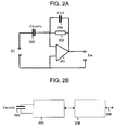
- Figure 2B is a diagram showing that the capacitor (203) is connected to a measuring device (205) to determine a capacitor capacity C nozzle .
- the measuring device may be connected to a model module (206) in order to determine the meniscus position. The correlation between the measured capacitor capacity C nozzle and the meniscus position of the ink near the exit opening to be determined is to be found in the model module.
- the capacity may be determined in various manners.
- Current I may be measured using a measuring device, for example, containing a 'charge amplifier'.
- a measuring device for example, containing a 'charge amplifier'.
- a disadvantage of this method is that determining the initial meniscus position - a static meniscus position - is too complicated and may lead to a larger measurement error.
- FIG. 2A shows an example of a measuring device in the form of a basic electronic diagram with which the instantaneous capacitor capacity, indicated by C nozzle (203) may be determined.
- a reference capacitor C ref (204), a large enough resistor R (202) and an op-amp (201) (differential amplifier) with amplification factor A o and a tilt frequency ⁇ v are used.
- the basic diagram may be modified, for example, to suppress noise and to compensate parasitic capacities.
- An alternating current is applied at the input of the measuring device, indicated by U i , after which the voltage at the output of the measuring device is measured, indicated by U o .
- the output voltage is compared to the input voltage in order to determine capacity C nozzle .
- FIG. 3 shows an electrical equivalent of the method of actuating an inkjet printer according to the invention.
- This electrical diagram applies for both types of controller: feedforward and feedback.
- the central unit in this diagram is processor (301). Within the processor (301), both types of control diagram may be used.
- This processor is either given a reference position or a reference variation via connection (302).
- the processor (301) receives the measured meniscus position of the ink near the exit opening of the model module (206) via connection (308).
- the variation of the meniscus position as a result of the actuation pulse may be determined by determining and storing the meniscus position at various times or continuously. This variation may, for example, be stored in a memory (not shown) that is available to the processor (301).
- the processor determines a signal for the electro-mechanical converter (303).
- the DA converter (304) feeds an analogue signal via connection (305) to amplifier (306).
- This amplifier then feeds the actuation pulse via connection (307) to the converter (303).
- the calculated error may be added to the actuation of the electro-mechanical converter (303) so that the error in the meniscus position becomes smaller.
- the actuation pulse mentioned may still be directly adjusted during actuation.
- the next actuation pulse may also be modified based on this stored variation as a result of the previous actuation pulse.
- a measuring circuit is also formed for determining the meniscus position near the exit opening of the duct, a control unit (processor 301) for modifying the actuation pulse.
- each duct may be actuated, measured and controlled in this manner.
- one processor unit is used for many tens or even hundreds of ink ducts.
- the number of processors required for an inkjet printer with many hundreds of ink ducts depends, inter alia, on the computing capacity required for adequate control of the actuation pulses.
- ILC 'Iterative Learning Control'
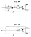
- Figure 4A is an example diagram showing 'Lifted ILC' control structure that may be carried out on the processor (301).
- the processor deducts the measured position (308) from the reference (desired) meniscus position (302).
- the result (401) i.e. the error in the position
- the result (401) is multiplied by learning matrix L (402) resulting in an adaptation of the new actuation (403) compared to the previous actuation.
- This adaptation (403) is added to the previous actuation pulse (405) that is delayed for one attempt via operator matrix Z -1 (404).
- This provides a new modified actuation pulse (406) for the electro-mechanical converter, with which the error in the meniscus position is reduced.
- the deterministic error - not the stochastic error - in the position may be reduced, providing the inkjet printer has an operation area for this, to the resolution of the measuring device by performing the cycle a number of times: actuating the electro-mechanical converter, measuring the meniscus position, deducting the measured meniscus position from the reference meniscus position, multiplying the difference by learning matrix L and calculating the new modified actuation pulse.
- FIG. 4B Another alternative actuation technology is a feedback actuation technology as diagrammatically illustrated in figure 4B.
- the processor (301) deducts the measured position (308) from the reference meniscus position (302).
- the result (401) i.e. the error in the meniscus position, is used to calculate a correction for the actuation pulse in feedback controller K FB , indicated by (407), leading to the current actuation being modified.
- Figure 5 is a diagram showing part of an inkjet printer.
- the printer comprises a roller (501) used to support a receiving medium (502) and move it along the four inkjet printheads (503).
- the roller (501) may rotate around its own axis as indicated by arrow A.
- a carriage (504) carries the four printheads (503), one for each of the colours cyan, magenta, yellow and black, and may be moved in reciprocation in a direction indicated by double arrow B, parallel to the roller (501). In this manner, the printheads (503) may move along the receiving medium (502).
- the carriage (504) is guided on a rod (505) and is driven by suitable means (not shown).
- each printhead (503) comprises eight ink ducts, each with its own exit opening (506), which form an imaginary line perpendicular to the axis of the roller (501).
- the number of ink ducts per printhead (503) is many times greater.
- Each ink duct is provided with a transducer, a measuring device to determine the capacitor capacity (not shown) according to the invention.
- Each printhead may also contain a control unit: an associated actuation and measuring circuit (not shown) according to figure 3 for modifying the actuation pulses.
- the ink duct, transducer, actuation circuit and measuring device form a system serving to eject ink drops in the direction of the roller (501).
- Figure 6A shows a view in the direction of arrow I from figure 1 B on a cross-section according to dotted line z-z'.
- a capacitor is shown.
- the electrically conducting parts in this embodiment do not run in parallel, but as the duct walls in the nozzle up to the exit openings are tapered, the electrically conducting parts are tapered.
- the two electrically conducting parts are indicated by dark mark-up (101, 102).
- the duct nozzle of this embodiment looks like the diagram as shown in figure 6B.
- the height of the nozzle is equal to h. During operation, the meniscus may be between these two positions.
- the sectional plane of the nozzle is square and the one in the direction of the exit opening continues to decrease in size (is tapered).
- the duct walls of the nozzle follow the same shape.
- the angles of the nozzle shape in this embodiment are determined by the crystalline angles of the silicon.
- Figure 7A shows a view in the direction indicated by the two arrows (J) from figure 6A on a cross-section of a duct wall (601) according to dotted line y-y'.
- Arrow r in figure 7A indicates the width of the duct wall.
- height h is 123*10 -6 meters.
- the width of a duct wall in the exit opening is 25*10 -6 meters.
- the length of the electrically conducting part is indicated as h'.
- Figure 7B shows an electrically conducting part from figure 6A (101 or 102) from a particular viewpoint perpendicular to the part.
- the length of the electrically conducting part is indicated as h'
- the width of the electrically conducting part in the exit opening as b
- the position of an infinitely small electrically conducting surface d A as x' is 25*10 -6 meters.
- a physical model may be derived for capacity value C nozzle depending on the meniscus position where: C nozzle ( x men ) ⁇ ⁇ o ⁇ r ⁇ o x men d A r
- e o is the dielectrical constant in vacuum
- e r is the relative dielectrical constant of the ink
- dA is an infinitely small electrically conducting surface at position x with a width r that contributes to the capacity
- r is the distance between the parts at position x that contributes to the capacity.
- position x is integrated from the zero position up to meniscus position x men in order to determine capacity value C nozzle .
- This provides a physical model showing a correlation between meniscus position x men and capacity value C nozzle .
- the method of producing the capacitor is not part of this invention. It will be understood by those skilled in the art that one embodiment of the capacitor for determining the meniscus position may for example, but not exclusively, be achieved as follows: manufacturing steps such as applying electrodes via micro-manipulation or micromechanical technologies, by applying and then drying electrodes of conducting pastes, or generally known IC manufacturing steps by application of part steps such as Reactive Ion Etching and Chemical Vapour Deposition.
Landscapes
- Particle Formation And Scattering Control In Inkjet Printers (AREA)
- Ink Jet (AREA)
Abstract
Description
- The invention relates to an inkjet printer comprising an inkjet printhead containing a substantially closed duct comprising an exit opening for ejecting ink drops from the duct. The invention furthermore relates to a method to be applied by an inkjet printer.
- An inkjet printer of this kind is known from
EP 1 378 360. The inkjet printer comprising an inkjet printhead fitted with a duct plate in which a number of parallel grooves are formed, each groove terminating in an exit opening. The duct plate is covered by a flexible plate so that the grooves form substantially closed ink ducts. A number of electro-mechanical converters (transducers) are provided on the flexible plate at the ducts so that each duct has a converter. During operation, the substantially closed duct is filled with ink. When a voltage is applied in the form of an actuation pulse across the electrodes of an electro-mechanical converter of this kind, this results in a deformation of the converter in the direction of the associated duct, so that the pressure in that duct increases suddenly. The known inkjet printhead may vary, for example, by variation in mechanical cohesion in the duct construction itself, or by variation at a certain time by actuation of adjacent converters. Furthermore, there may, for example, be variations in duct pressure, printhead temperature and ink viscosity. By measuring the electrical impedance of the entire transmission path up to the drop formation process and determining the produced effect of the actuation pulse in the duct based on this measurement, the effect of these parameters may be measured together. This may then be used to adapt the actuation pulse to ultimately produce the desired drop ejection. - In order to improve the drop ejection of the known inkjet printer even further, the inventor has realised that an improvement may be achieved by locally determining the meniscus position of the ink in the duct.
- To this end, an inkjet printer has been invented according to the preamble of
claim 1, characterised in that the duct comprises two electrically conducting parts, where each part has been fitted against a duct wall, these parts extending to the vicinity of the exit opening and forming a capacitor together, and the inkjet printer furthermore being fitted with a measuring device in order to determine the capacity of the capacitor. - An inkjet printer according to the invention may be used to easily determine the meniscus position of the ink in the vicinity of the exit opening by measuring the capacity. In the vicinity of the exit opening, the duct may be filled with air, ink or a mixture of air and ink. During operation, the meniscus position will be between two electrically conducting parts. Ink has a different dielectrical constant compared to air, which is why, for example, the air between the two electrically conducting parts contribute to a lesser extent to the value of the capacitor capacity than the ink between the two electrically conducting parts. By applying a voltage across the two electrically conducting parts, electrons will move (current). Here, the current produced depends on the value of the capacity and the applied voltage. The capacity may be measured so that the meniscus position may be determined. It will be understood by those skilled in the art that "an electrically conducting part fitted against a duct wall" may also mean, for example, that an electrically conducting part is integrated into a duct wall.
- According to one embodiment of the invention, a nozzle plate is fitted against the inkjet printhead so that the exit opening of the duct coincides with a part of the duct (nozzle) in the nozzle plate, where the inkjet printer comprises an electrical connection between the capacitor and the measuring device, with at least a part of the connection being located between the nozzle plate and the inkjet printhead. When an ink drop is ejected, ink may undesirably stick to the outside of the inkjet printhead on the nozzle plate, causing the outside of the nozzle plate to become contaminated with ink. An unprotected electrical connection between the capacitor and the measuring device across the outside of the inkjet printhead and the nozzle plate, where the outside is humid due to undesired ink, has an undesirable effect on the capacity measured, so that the meniscus position cannot be determined accurately. By integrating the electrical connection in a well-screened state into the embodiment of the inkjet printhead, the measurement of the capacity is not distorted.
- With an inkjet printer according to the invention, a method may be applied comprising an inkjet printhead containing a substantially closed duct comprising an exit opening, said duct being essentially filled with ink, where a meniscus of the ink is located in the vicinity of the exit opening and the duct is fitted with two electrically conducting parts, each part being fitted against a duct wall, these parts extending to the vicinity of the exit opening and forming a capacitor together, the method comprising: determining a capacity of the capacitor and determining the meniscus position based on the capacity.
- A voltage applied across the two electrically conducting parts produces an electron current that is dependent the capacity and the voltage. This capacity may be determined if the voltage and the current are known. This makes it possible to quickly and accurately determine the meniscus position of the ink in the vicinity of the exit opening at any specific moment. For example, it may be used to determine whether a minimum or maximum fill level of the ink in the duct has been reached as required to enable an ink drop to be formed during ejection, or whether the meniscus is located in an area that is suitable to be able to eject an ink drop. Here, the minimum and maximum fill levels of the ink may be expressed in a minimum and a maximum capacity. If there is insufficient ink in the duct, it is, for example, necessary to wait until the ink has sufficiently filled the duct, after which an ink drop may be ejected from the exit opening. The value of the capacity is a direct representative of the meniscus position and may therefore be easily converted based on a model that determines the correlation between the capacity value and the meniscus position.
- Another embodiment of the method comprises imposing an actuation pulse on an actuator which is operationally connected to the duct so that an ink drop is ejected from the exit opening, and determining a variation of the meniscus position as a result of the actuation pulse. This method may be used to determine the meniscus position at various moments in time to be able to quickly and accurately determine a variation of the position. Thus, the variation of the meniscus position may be determined for the period when, for example, a drop is formed in the duct and the ink stabilises in the duct after the drop has formed. An advantage is that the variation of the meniscus position may be used to, for example, determine whether the ink is sufficiently at rest to be able to eject an ink drop. If the ink has insufficiently reached a rest state, it is possible, for example, to wait until this has been reached.
- Another embodiment of the invention comprises: modifying the actuation pulse mentioned based on the variation. In other words, the variation of the meniscus position is measured during the application of the actuation pulse, so that the effect of this pulse may be determined simultaneously with its application (in real-time). In this manner, it is possible to adapt the pulse during the application thereof, if necessary, in order to achieve a desired variation of the meniscus position in order to produce correct drop formation. If, for example, it appears at the start of the pulse that the meniscus position is increasing much too quickly in the direction of the exit opening, for whatever reason, the pulse may be modified by adjusting it in its further course based on this information. Another example is that if the ink in the duct has insufficiently reached a rest state, the pulse, and therefore also the ink, may be actively influenced so that the ink reaches a sufficient rest state faster.
- Another embodiment according to the invention comprises modifying another actuation pulse based on the variation. In other words, the variation of the meniscus position is measured and, based on this data, the actuation pulse may be modified before the next ink drop, for example to achieve improved drop formation. The advantage of this method compared to the previous embodiment is that this leaves more time to carry out complex calculations. If, for example, it appears at the start of the pulse that the meniscus position is increasing much too quickly in the direction of the exit opening, for whatever reason, the next pulse may be modified by adjusting it in its further course based on this information. Another example is that if the ink in the duct has insufficiently quickly reached a rest state, the next pulse may actively influence the ink, so that it reaches a sufficient rest state faster.
- Another embodiment of the invention comprises: comparing the variation to a reference variation. A reference variation is a variation of the meniscus position that results in a certain objective being achieved. A reference variation may be predetermined, for example, in a special test arrangement. For example, a reference variation may be determined for a drop ejection with the objective of achieving a desired drop size and a desired drop speed. Thus various reference variations, for example, may be determined, each for different objectives. One particular objective may be, for example, to quickly achieve a rest state for the ink in the duct after a drop has been ejected, to compensate for cross-talk in an adjacent duct, to achieve a specific drop size at drop ejection and a specific drop speed at drop ejection. The reference variation may be stored in the inkjet printer according to the invention, after which this reference variation is compared to the actual variation during operation. When comparing the data, a discrepancy may be detected between the actual variation and the reference variation. A discrepancy could, for example, be caused by an air bubble in the duct, partial clogging of the ink, or another dynamic behaviour in the ink-filled duct caused by ageing of the inkjet printhead. The measured variation of the meniscus position will normally follow a fixed pattern. An air bubble anywhere in the duct may be detected by there being a specific discrepancy between the measured variation of the meniscus position and its reference variation. If there is an air bubble in the duct, the printing process is, for example, interrupted until the air bubble has dissolved, after which an ink drop may be ejected from the exit opening, or a pressure pulse may, for example, be imposed on the actuator in between two print passes, i.e. at a carriage return, so that the air bubble is expelled from the exit opening.
- Another embodiment of the invention comprises a feedforward controller known as ILC (Iterative Learning Control) actuation technology. This control technology allows for optimum actuation pulses to be systematically generated with which preset objectives may be achieved. This method may be used to quickly and accurately determine the meniscus position at various moments in time, and thus also a variation of the position, for example for the period when a drop is formed in the duct and for the period when the ink stabilises in the duct after the drop has formed. ILC actuation technology compares the variation to a reference variation - a variation of the meniscus position that results in a specific objective being achieved - and modifies an actuation pulse so that the discrepancy between the actual variation and the reference variation is eliminated. ILC actuation technology is suitable for modifying repetitive similar tasks to a predetermined objective: to achieve higher jet frequencies, to eliminate cross-talk, to compensate for changed dynamics or to enable drop size modulation. This ILC actuation technology has the extra advantage that it is less calculation intensive compared to feedback control technology.
- By applying the method in an inkjet printer according to the invention, it is possible to take effects of printhead ageing into account so that there is no more noticeable effect on the drop ejection. Any effect that ageing has on the drop ejection process may be corrected by application of this method. For example, if wear of the printhead leads to a deviant variation of the meniscus position, then the actuation pulse may be modified so that the correct variation of the meniscus position is achieved. A deviant variation of the meniscus position could occur, for example, reduction of the expansion of the converter in response to a given pulse, wear of the exit opening, weakening of the flexible plate, cracks in the printhead, or loosening of connections, etc. The compensation of the effects of ageing may be effected by updating each actuation pulse, or by measuring the effects of ageing at certain times, for example, during a service call, and modifying the actuation pulse to said measurement. The latter embodiment is easy to implement and is often sufficient if the printhead is not ageing quickly.
- The jetting frequency may be made much higher using the method in an inkjet printer according to the present invention, . By modifying the actuation pulse, the meniscus movement may be faster brought to rest at the desired meniscus position . For example, by forming the actuation pulse after the drop ejection in such a manner that it yields a pressure wave opposed to the pressure wave of the kind passing through the ducts, the damping may take place in a much shorter time so that the meniscus position is at rest in a short time and at the correct location. As a result, the next actuation pulse may be given more quickly while maintaining good drop properties. It is also possible to let the next actuation pulse take place in any manner whatsoever, i.e. without a distinctly active damping, after a prior drop ejection and actively correct the variation of the meniscus position.
- Cross-talk, i.e. the influencing of the drop ejection process in one duct by the actuation of another duct, may also be readily obviated by application of the method in an inkjet printer according to the invention. If actuation of a transducer in one duct has an effect on the state in an adjacent duct, the effect on the meniscus position in the adjacent duct may be measured and corrected by modifying the actuation pulse there by application of the method according to the invention.
- Drop size modulation may be achieved by directly relating drop properties to the variation of the ink position over time. By storing the corresponding desired meniscus variation for a number of desired drop volumes (drop sizes), these profiles become available for the actuation algorithm of the transducer. If, for example, a specific drop size is required, the associated reference variation may be used with which the actuation pulse is modified so that the desired meniscus variation is achieved.
- Furthermore, it is possible to vary not only the drop volume in the manner shown, but also other drop properties such as the speed. An expansion on this is possible with a model describing the transfer between the drop properties and the meniscus movement. By varying the meniscus movement over a whole range of movements and measuring the drop properties, such as the speed and drop size, at each movement, a model of the transfer may be determined. Based on this model, the actuation algorithm itself may be used to calculate the reference variation of the meniscus position given a certain objective such as a specific drop size and speed, use them as a reference variation and the variation will converge accordingly.
- The invention will now be further explained with reference to the following figures and examples in which specific embodiments of the present invention are outlined.
- Fig. 1A is a diagram showing a cross-section of a capacitor in the inkjet printer duct.
- Fig. 1 B is a diagram showing a cross-section of a capacitor in the duct filled with ink.
- Fig. 1C is a diagram showing a side view of a capacitor in the duct.
- Fig. 2A is a diagram showing a charge amplifier.
- Fig. 2B is a diagram showing a measuring device used to determine a capacity of the capacitor.
- Fig. 3 is a diagram showing an electrical equivalent of the method of actuating an inkjet printhead according to the invention.
- Fig. 4A is a diagram showing ILC actuation technology.
- Fig. 4B is a diagram showing another example of an actuation technology.
- Fig. 5 is a diagram showing an inkjet printer according to the invention.
- Fig. 6A is an example showing two electrically conducting parts in a duct.
- Fig. 6B is an example showing a nozzle shape.
- Fig. 7A-C is an example showing a physical model of an embodiment.
- Example 1 is a physical model showing an embodiment of the capacitor.
- Figure 1A is an example showing a part of the inkjet printhead according to the invention, i.e. a cross-section of a substantially closed
duct 103 comprising an exit opening (104) used to eject an inkjet drop from the duct. The duct comprises two electrically conducting parts (electrodes), each of which having been fitted to a duct wall, indicated by 101 and 102. These parts extend to the exit opening and have such an effect on each other that they possibly cause charge accumulation to occur on the parts so that they form a capacitor together. An electrical connection (105, 106) (wiring) may be used between the capacitor and the measuring device to measure the capacitor. In order to eject an inkjet drop from the duct, an actuation pulse is imposed on the transducer (111) causing this transducer to expand in the direction of the duct (103) and producing a pressure wave so that an inkjet drop is ejected from the duct. - Figure 1 B shows an example of a part of a substantially closed duct (103) comprising an exit opening (104) used to eject inkjet drops from the duct. The duct comprises two electrically conducting parts (electrodes), each of which having been fitted to a duct wall, indicated by 101 and 102. These parts extend to the exit opening and have such an effect on each other that they possibly cause charge accumulation to occur on the [arts by a voltage across the elements so that they form a capacitor together. This capacitor is also indicated by 203 in figure 2B. The parts extend in such a manner that the ink meniscus is between the electrically conduction parts while in operation. The electrically conducting parts may, for example, be embodied in aluminium. The parts extend to the vicinity of the exit opening so that the meniscus position may be measured.
- According to one embodiment, the exit opening (104) of the duct coincides with the exit opening of a nozzle in a nozzle plate. Figure 1B shows a part of the nozzle plate (109). A nozzle plate may, for example, be a plate of a non-conducting substrate, such as silicon with an approximate thickness between 25 and 150 micrometers. This nozzle plate is fitted against the exit of the ducts so that the duct and the nozzle plate comprise an exit opening (104) together.
- To measure the capacitor, an electrical connection (105, 106) (wiring) may run between the capacitor and the measuring device, for at least a part of the connection between the nozzle plate and the inkjet printhead or along the outside (not shown) of the inkjet printhead. A disadvantage of an electrical connection running along the outside of the inkjet printhead across the nozzle plate is that any ink drop on the electrical connection produces a distorting signal when determining the capacity of the capacitor. It is preferable for the electrical connection between the capacitor and the measuring device to run at least partly between the nozzle plate and the inkjet printhead, so that the distorting signal is not produced.
- Figure 1 B shows the duct of the inkjet printhead filled with ink as indicated by shading, where the direction of the ink drop ejection is indicated by 107. The instantaneous meniscus position indicated by 108 may be determined using the capacitor. During an actuation cycle, the meniscus may be slightly convex, concave or flat, which may be taken into account when determining the meniscus position.
- Figure 1C shows a view in the direction of arrow I on a cross-section at the level of dotted line z-z' from figure 1 B. Figure 1C shows an example of a capacitor in the nozzle. According to this embodiment, the duct walls up to the exit opening are tapered. Figure 1C is a diagram showing the two electrically conducting parts indicated by dark mark-up (101, 102). It should be understood that in another possible embodiment of the duct, a capacitor may also be applied near the exit opening.
- The following formula applies for capacitor capacity C near the exit opening when it is fully filled with ink:

- In
formula 1, e o is the dielectrical constant in vacuum, e r is the relative dielectrical constant of the ink, Aeff (is Arms) is the surface that contributes to the capacity, reff (is rrms) is the distance between the parts, which contributes to the capacity, Q is the charge stored on the conducting parts and V the voltage applied between the conducting parts. Distance reff (is rrms) and surface Aeff (is Arms) depend on the construction of the parts and their values may be calculated if the construction is known. - The capacity of the capacitor depends on an actual meniscus position of the ink near the exit opening. For example, this may be because the ink has a stronger dielectrical property than air. As a result, the part that is filled with ink between the two electrically conducting parts will contribute more to the capacity than the part that is filled with air.
- For one embodiment of the capacitor, a model may be derived that shows a correlation between a capacitor capacity Cnozzle and a meniscus position xmen. This model may, for example, be a physical model or a measured model that is determined by measurements carried out on this embodiment. By using, for example, a laser vibrometer, the meniscus position may be determined accurately. At the same time, the capacity may be determined using a measuring device. By combining the data from the two measurements, a measured model may be determined. A physical model may be derived for a concrete embodiment of a capacitor near an exit opening. The physical model may be simplified, for example, as the effect of air on the value of the capacitor capacity (dielectrical constant) may be much smaller than the effect of the ink on the capacity of the capacitor. The effect of air on the value of the capacity may therefore be neglected in some cases.
- Figure 2B is a diagram showing that the capacitor (203) is connected to a measuring device (205) to determine a capacitor capacity Cnozzle. According to another embodiment, the measuring device may be connected to a model module (206) in order to determine the meniscus position. The correlation between the measured capacitor capacity Cnozzle and the meniscus position of the ink near the exit opening to be determined is to be found in the model module.
- The capacity may be determined in various manners. One manner of determining the meniscus position is that during inkjet printhead operation, a constant voltage V is present across both parts and as such, also a certain charge Q on the parts. Any movement of the meniscus position leads to a change in the capacity by a change in charge Q with current I, differentiated over time as shown in formula 1:

- Current I may be measured using a measuring device, for example, containing a 'charge amplifier'. A disadvantage of this method is that determining the initial meniscus position - a static meniscus position - is too complicated and may lead to a larger measurement error.
- It would be better to use another method for determining the meniscus position. Figure 2A shows an example of a measuring device in the form of a basic electronic diagram with which the instantaneous capacitor capacity, indicated by Cnozzle (203) may be determined. In this diagram, a reference capacitor Cref (204), a large enough resistor R (202) and an op-amp (201) (differential amplifier) with amplification factor Ao and a tilt frequency τv are used. The basic diagram may be modified, for example, to suppress noise and to compensate parasitic capacities.
An alternating current is applied at the input of the measuring device, indicated by Ui, after which the voltage at the output of the measuring device is measured, indicated by Uo. The output voltage is compared to the input voltage in order to determine capacity Cnozzle. The following formula applies for the transfer between the input voltage and the output voltage:
where ω equals 2 * pi * frequency, where frequency is the frequency of input signal Ui. For a large enough resistor R and a jωτv /Ao much smaller than 1, the effect of both may be neglected in the transfer, so that a simple transfer remains:
As reference capacity Cref and the input voltage are known, capacity Cnozzle may be easily determined by measuring the output voltage. - Figure 3 shows an electrical equivalent of the method of actuating an inkjet printer according to the invention. This electrical diagram applies for both types of controller: feedforward and feedback. The central unit in this diagram is processor (301). Within the processor (301), both types of control diagram may be used. This processor is either given a reference position or a reference variation via connection (302). The processor (301) receives the measured meniscus position of the ink near the exit opening of the model module (206) via connection (308). The variation of the meniscus position as a result of the actuation pulse may be determined by determining and storing the meniscus position at various times or continuously. This variation may, for example, be stored in a memory (not shown) that is available to the processor (301). The processor determines a signal for the electro-mechanical converter (303). For this purpose, it feeds a signal to the DA converter (304), which feeds an analogue signal via connection (305) to amplifier (306). This amplifier then feeds the actuation pulse via connection (307) to the converter (303). By deducting the measured position from the reference position, the calculated error may be added to the actuation of the electro-mechanical converter (303) so that the error in the meniscus position becomes smaller. Thus, the actuation pulse mentioned may still be directly adjusted during actuation. Alternatively, by storing the variation of the meniscus position, the next actuation pulse may also be modified based on this stored variation as a result of the previous actuation pulse.
- In this manner, in addition to an actuation circuit for the electromechanical converter (transducer), a measuring circuit is also formed for determining the meniscus position near the exit opening of the duct, a control unit (processor 301) for modifying the actuation pulse.
- In principle, each duct may be actuated, measured and controlled in this manner. According to one embodiment, one processor unit is used for many tens or even hundreds of ink ducts. The number of processors required for an inkjet printer with many hundreds of ink ducts depends, inter alia, on the computing capacity required for adequate control of the actuation pulses.
- There are various alternative actuation technologies for an inkjet printer according to the invention. The 'Iterative Learning Control' (ILC) actuation technology is the preferred choice, which is a feedforward actuation technology. ILC is suitable for repetitive tasks such as ejecting ink drops from an exit opening of an inkjet printer.
- Figure 4A is an example diagram showing 'Lifted ILC' control structure that may be carried out on the processor (301). The processor deducts the measured position (308) from the reference (desired) meniscus position (302). Next, the result (401), i.e. the error in the position, is multiplied by learning matrix L (402) resulting in an adaptation of the new actuation (403) compared to the previous actuation. This adaptation (403) is added to the previous actuation pulse (405) that is delayed for one attempt via operator matrix Z-1 (404). This provides a new modified actuation pulse (406) for the electro-mechanical converter, with which the error in the meniscus position is reduced. The deterministic error - not the stochastic error - in the position may be reduced, providing the inkjet printer has an operation area for this, to the resolution of the measuring device by performing the cycle a number of times: actuating the electro-mechanical converter, measuring the meniscus position, deducting the measured meniscus position from the reference meniscus position, multiplying the difference by learning matrix L and calculating the new modified actuation pulse.
- Another alternative actuation technology is a feedback actuation technology as diagrammatically illustrated in figure 4B. The processor (301) deducts the measured position (308) from the reference meniscus position (302). Next, the result (401), i.e. the error in the meniscus position, is used to calculate a correction for the actuation pulse in feedback controller KFB, indicated by (407), leading to the current actuation being modified.
- Figure 5 is a diagram showing part of an inkjet printer. According to this embodiment, the printer comprises a roller (501) used to support a receiving medium (502) and move it along the four inkjet printheads (503). The roller (501) may rotate around its own axis as indicated by arrow A. A carriage (504) carries the four printheads (503), one for each of the colours cyan, magenta, yellow and black, and may be moved in reciprocation in a direction indicated by double arrow B, parallel to the roller (501). In this manner, the printheads (503) may move along the receiving medium (502). The carriage (504) is guided on a rod (505) and is driven by suitable means (not shown).
According to the embodiment as shown in figure 5, each printhead (503) comprises eight ink ducts, each with its own exit opening (506), which form an imaginary line perpendicular to the axis of the roller (501). According to a practical embodiment of a printing device, the number of ink ducts per printhead (503) is many times greater. Each ink duct is provided with a transducer, a measuring device to determine the capacitor capacity (not shown) according to the invention. Each printhead may also contain a control unit: an associated actuation and measuring circuit (not shown) according to figure 3 for modifying the actuation pulses. In this manner, the ink duct, transducer, actuation circuit and measuring device form a system serving to eject ink drops in the direction of the roller (501). However, it is not essential for all the elements of the actuation and measuring device to be physically incorporated in the printheads (503). It is also possible for some parts to be located, for example, in the carriage (504) or even a more remote part of the printer, there being connections to components in the printheads (503) themselves. In this manner, these parts nevertheless form a functional part of the printheads without actually being physically incorporated therein. If the converters are actuated image-wise, an image forms, built up of individual ink drops, on the receiving medium (502). - Below, an example is shown of a physical model of an embodiment of the capacitor.
Figure 6A shows a view in the direction of arrow I from figure 1 B on a cross-section according to dotted line z-z'. In here, a capacitor is shown. The electrically conducting parts in this embodiment do not run in parallel, but as the duct walls in the nozzle up to the exit openings are tapered, the electrically conducting parts are tapered. The two electrically conducting parts are indicated by dark mark-up (101, 102). In side view, the duct nozzle of this embodiment looks like the diagram as shown in figure 6B. The height of the nozzle is equal to h. During operation, the meniscus may be between these two positions. The one end of the two electrically conducting parts starts at position x = 0 and the other end of the parts ends at position x = h. According to this embodiment, the sectional plane of the nozzle is square and the one in the direction of the exit opening continues to decrease in size (is tapered). The duct walls of the nozzle follow the same shape. The angles of the nozzle shape in this embodiment are determined by the crystalline angles of the silicon. - Figure 7A shows a view in the direction indicated by the two arrows (J) from figure 6A on a cross-section of a duct wall (601) according to dotted line y-y'. Arrow r in figure 7A indicates the width of the duct wall. According to one embodiment, the angles are equal to the silicon crystalline angles, indicated by α = 35.3 degrees and δ = 54.7 degrees respectively. According to one embodiment, height h is 123*10-6 meters. The width of a duct wall in the exit opening is 25*10-6 meters. The following formula applies for distance r that depends on position x:

- Figure 7C shows a side view on an electrically conducting part (101 or 102), where the one end starts at position x = 0 and the other end of this part ends at position x = h. The silicon crystalline angle is indicated as α = 35.3 degrees. The length of the electrically conducting part is indicated as h'. Where:

- Figure 7B shows an electrically conducting part from figure 6A (101 or 102) from a particular viewpoint perpendicular to the part. The length of the electrically conducting part is indicated as h', the width of the electrically conducting part in the exit opening as b, and the position of an infinitely small electrically conducting surface dA as x'. According to one embodiment, this width b is 25*10-6 meters. Two angles of each of the 4 duct walls of the nozzle are According to one embodiment y = 60 degrees. The following formula applies for an infinitely small surface dA at position x:

- Based on this data from one embodiment, a physical model may be derived for capacity value Cnozzle depending on the meniscus position where:

- In Formula 5, e o is the dielectrical constant in vacuum, e r is the relative dielectrical constant of the ink, dA is an infinitely small electrically conducting surface at position x with a width r that contributes to the capacity, and r is the distance between the parts at position x that contributes to the capacity. In formula 5, the effect of the air-part between the electrically conducting parts on the value of the capacity has been neglected. In formula 5, position x is integrated from the zero position up to meniscus position xmen in order to determine capacity value Cnozzle. When surface dA (formula 4) and distance r (formula 6) are expressed in position x, height h and the construction angles of the nozzle in formula 5, this provides the following formula 6 for the derived physical model:

- This provides a physical model showing a correlation between meniscus position xmen and capacity value Cnozzle.
- The method of producing the capacitor is not part of this invention. It will be understood by those skilled in the art that one embodiment of the capacitor for determining the meniscus position may for example, but not exclusively, be achieved as follows: manufacturing steps such as applying electrodes via micro-manipulation or micromechanical technologies, by applying and then drying electrodes of conducting pastes, or generally known IC manufacturing steps by application of part steps such as Reactive Ion Etching and Chemical Vapour Deposition.
Claims (8)
- An inkjet printer comprising an inkjet printhead containing a substantially closed duct comprising an exit opening used to eject ink drops from the duct, characterised in that the duct comprises two electrically conducting parts, each of which having been fitted to a duct wall, these elements extending to the vicinity of the exit opening and forming a capacitor together, and the inkjet printer furthermore being fitted with a measuring device in order to determine the capacity of the capacitor.
- An inkjet printer according to claim 1, where a nozzle plate is fitted against the inkjet printhead so that the exit opening of the duct coincides with a nozzle in the nozzle plate, characterised in that the inkjet printer comprises an electrical connection between the capacitor and the measuring device, with at least a part of the connection being located between the nozzle plate and the inkjet printhead.
- A method to be applied in an inkjet printer comprising an inkjet printhead containing a substantially closed duct comprising an exit opening, said duct being essentially filled with ink, where a meniscus of the ink is located in the vicinity of the exit opening, and the duct comprises two electrically conducting parts, each part having been fitted against a duct wall, these elements extending to the vicinity of the exit opening and forming a capacitor together,
the method comprising:- determining a capacity of the capacitor, and- determining the meniscus position based on the capacity. - A method according to claim 3, furthermore comprising:- imposing an actuation pulse on an actuator being operationally connected to the duct so that an ink drop is ejected from the exit opening, and- determining a variation of the meniscus position as a result of the actuation pulse.
- A method according to claim 4, furthermore comprising:- modifying said actuation pulse based on the variation.
- A method according to claim 4, furthermore comprising:- modifying another actuation pulse based on the variation.
- A method according to claims 4-6, furthermore comprising:- comparing the variation to a reference variation.
- A method according to either one of claims 5 or 6, where the actuation pulse is modified using a form of ILC actuation technology.
Applications Claiming Priority (1)
| Application Number | Priority Date | Filing Date | Title |
|---|---|---|---|
| NL1028236A NL1028236C2 (en) | 2005-02-10 | 2005-02-10 | Inkjet printer and method for controlling this inkjet printer. |
Publications (2)
| Publication Number | Publication Date |
|---|---|
| EP1690686A1 true EP1690686A1 (en) | 2006-08-16 |
| EP1690686B1 EP1690686B1 (en) | 2012-04-11 |
Family
ID=35004167
Family Applications (1)
| Application Number | Title | Priority Date | Filing Date |
|---|---|---|---|
| EP06101152A Expired - Lifetime EP1690686B1 (en) | 2005-02-10 | 2006-02-01 | Inkjet printer and method of actuating this inkjet printer |
Country Status (5)
| Country | Link |
|---|---|
| US (1) | US20060176339A1 (en) |
| EP (1) | EP1690686B1 (en) |
| JP (1) | JP2006218863A (en) |
| AT (1) | ATE552975T1 (en) |
| NL (1) | NL1028236C2 (en) |
Cited By (1)
| Publication number | Priority date | Publication date | Assignee | Title |
|---|---|---|---|---|
| EP2712342A4 (en) * | 2011-10-24 | 2015-08-05 | Hewlett Packard Development Co | Inkjet printhead device, fluid ejection device, and method thereof |
Families Citing this family (3)
| Publication number | Priority date | Publication date | Assignee | Title |
|---|---|---|---|---|
| NL1028546C2 (en) * | 2005-03-15 | 2006-09-18 | Oce Tech Bv | Piezo inkjet printer. |
| WO2013062517A1 (en) | 2011-10-24 | 2013-05-02 | Hewlett-Packard Development Company, L.P. | Inkjet printing system, fluid ejection system, and method thereof |
| JP6582385B2 (en) * | 2014-10-10 | 2019-10-02 | 株式会社リコー | Droplet ejection apparatus, droplet ejection method, and program |
Citations (9)
| Publication number | Priority date | Publication date | Assignee | Title |
|---|---|---|---|---|
| US4241357A (en) * | 1979-09-24 | 1980-12-23 | Exxon Research & Engineering Co. | Method and apparatus for operating an ink jet |
| JPH02107452A (en) * | 1988-10-17 | 1990-04-19 | Seiko Epson Corp | Ink level detection device |
| JPH02217252A (en) * | 1989-02-17 | 1990-08-30 | Canon Inc | Ink jet recording head |
| JPH05338161A (en) * | 1992-06-11 | 1993-12-21 | Fuji Electric Co Ltd | Inkjet recording head |
| JPH081947A (en) * | 1994-06-17 | 1996-01-09 | Matsushita Electric Ind Co Ltd | INKJET HEAD INK TEMPERATURE DETECTING DEVICE AND METHOD |
| EP0764537A2 (en) * | 1995-09-21 | 1997-03-26 | Nec Corporation | Toner content monitoring method and system for ink jet recording head |
| JPH1029321A (en) * | 1996-07-17 | 1998-02-03 | Canon Inc | Ink jet printing apparatus and printing method |
| JP2000318178A (en) * | 1999-05-10 | 2000-11-21 | Brother Ind Ltd | Ink jet recording device |
| EP1378360A1 (en) | 2002-07-05 | 2004-01-07 | Océ-Technologies B.V. | A method of controlling an inkjet printhead, an inkjet printhead suitable for use of said method, and an inkjet printer comprising said printhead |
Family Cites Families (2)
| Publication number | Priority date | Publication date | Assignee | Title |
|---|---|---|---|---|
| US6908167B2 (en) * | 2002-08-01 | 2005-06-21 | Konica Corporation | Ink-jet recording apparatus |
| WO2004028815A1 (en) * | 2002-09-24 | 2004-04-08 | Konica Minolta Holdings, Inc. | Method for manufacturing electrostatic attraction type liquid discharge head, method for manufacturing nozzle plate, method for driving electrostatic attraction type liquid discharge head, electrostatic attraction type liquid discharging apparatus, and liquid discharging apparatus |
-
2005
- 2005-02-10 NL NL1028236A patent/NL1028236C2/en not_active IP Right Cessation
-
2006
- 2006-02-01 AT AT06101152T patent/ATE552975T1/en active
- 2006-02-01 EP EP06101152A patent/EP1690686B1/en not_active Expired - Lifetime
- 2006-02-03 JP JP2006027453A patent/JP2006218863A/en not_active Withdrawn
- 2006-02-09 US US11/349,950 patent/US20060176339A1/en not_active Abandoned
Patent Citations (9)
| Publication number | Priority date | Publication date | Assignee | Title |
|---|---|---|---|---|
| US4241357A (en) * | 1979-09-24 | 1980-12-23 | Exxon Research & Engineering Co. | Method and apparatus for operating an ink jet |
| JPH02107452A (en) * | 1988-10-17 | 1990-04-19 | Seiko Epson Corp | Ink level detection device |
| JPH02217252A (en) * | 1989-02-17 | 1990-08-30 | Canon Inc | Ink jet recording head |
| JPH05338161A (en) * | 1992-06-11 | 1993-12-21 | Fuji Electric Co Ltd | Inkjet recording head |
| JPH081947A (en) * | 1994-06-17 | 1996-01-09 | Matsushita Electric Ind Co Ltd | INKJET HEAD INK TEMPERATURE DETECTING DEVICE AND METHOD |
| EP0764537A2 (en) * | 1995-09-21 | 1997-03-26 | Nec Corporation | Toner content monitoring method and system for ink jet recording head |
| JPH1029321A (en) * | 1996-07-17 | 1998-02-03 | Canon Inc | Ink jet printing apparatus and printing method |
| JP2000318178A (en) * | 1999-05-10 | 2000-11-21 | Brother Ind Ltd | Ink jet recording device |
| EP1378360A1 (en) | 2002-07-05 | 2004-01-07 | Océ-Technologies B.V. | A method of controlling an inkjet printhead, an inkjet printhead suitable for use of said method, and an inkjet printer comprising said printhead |
Non-Patent Citations (6)
| Title |
|---|
| PATENT ABSTRACTS OF JAPAN vol. 014, no. 319 (M - 0996) 9 July 1990 (1990-07-09) * |
| PATENT ABSTRACTS OF JAPAN vol. 014, no. 517 (M - 1047) 13 November 1990 (1990-11-13) * |
| PATENT ABSTRACTS OF JAPAN vol. 018, no. 173 (M - 1581) 24 March 1994 (1994-03-24) * |
| PATENT ABSTRACTS OF JAPAN vol. 1996, no. 05 31 May 1996 (1996-05-31) * |
| PATENT ABSTRACTS OF JAPAN vol. 1998, no. 06 30 April 1998 (1998-04-30) * |
| PATENT ABSTRACTS OF JAPAN vol. 2000, no. 14 5 March 2001 (2001-03-05) * |
Cited By (4)
| Publication number | Priority date | Publication date | Assignee | Title |
|---|---|---|---|---|
| EP2712342A4 (en) * | 2011-10-24 | 2015-08-05 | Hewlett Packard Development Co | Inkjet printhead device, fluid ejection device, and method thereof |
| US9327512B2 (en) | 2011-10-24 | 2016-05-03 | Hewlett-Packard Development Company, L.P. | Inkjet printhead device, fluid ejection device, and method thereof |
| US9862186B2 (en) | 2011-10-24 | 2018-01-09 | Hewlett-Packard Development Company, L.P. | Inkjet printhead device, fluid ejection device, and method thereof |
| US10369785B2 (en) | 2011-10-24 | 2019-08-06 | Hewlett-Packard Development Company, L.P. | Inkjet printhead device, fluid ejection device, and method thereof |
Also Published As
| Publication number | Publication date |
|---|---|
| EP1690686B1 (en) | 2012-04-11 |
| ATE552975T1 (en) | 2012-04-15 |
| JP2006218863A (en) | 2006-08-24 |
| US20060176339A1 (en) | 2006-08-10 |
| NL1028236C2 (en) | 2006-08-11 |
Similar Documents
| Publication | Publication Date | Title |
|---|---|---|
| US7997675B2 (en) | Piezoelectric head inspection device and droplet jetting device | |
| US6428135B1 (en) | Electrical waveform for satellite suppression | |
| EP1378360B1 (en) | A method of controlling an inkjet printhead, an inkjet printhead suitable for use of said method, and an inkjet printer comprising said printhead | |
| JP3337912B2 (en) | Driving method of inkjet head and inkjet apparatus for executing the same | |
| EP2098371B1 (en) | Liquid ejecting method, liquid ejecting head, and liquid ejecting apparatus | |
| JP2001260350A (en) | Ink jet recording device | |
| US6910751B2 (en) | Method of controlling an inkjet printer, and inkjet printhead suitable for the use of this method, and an inkjet printer provided with this printhead | |
| US6948791B2 (en) | Liquid ejecting apparatus | |
| EP1690686B1 (en) | Inkjet printer and method of actuating this inkjet printer | |
| JP2000071437A (en) | Ink jet recording apparatus, storage medium, and control table creation method | |
| EP2098370B1 (en) | Liquid ejecting method, liquid ejecting head, and liquid ejecting apparatus | |
| JP2823977B2 (en) | Droplet marking apparatus and method | |
| JP2005047207A (en) | Inkjet printing machine | |
| EP1151868B1 (en) | Method for using highly energetic droplet firing events to improve droplet ejection reliability | |
| US6450602B1 (en) | Electrical drive waveform for close drop formation | |
| JP3006577B2 (en) | Inkjet head | |
| JP2002225250A (en) | Ink jet recording device | |
| US5517216A (en) | Ink jet printer employing time of flight control system for ink jet printers | |
| JP2001071538A (en) | Driving method of inkjet head | |
| EP4414175A1 (en) | Liquid ejection head, liquid ejection device, and inkjet printer | |
| JP2011084028A (en) | Liquid ejection method and liquid ejection device | |
| US20070273721A1 (en) | Method for obtaining an image, and an ink jet printer for performing the method | |
| US20090079772A1 (en) | Method for obtaining an image with an ink jet printer and a printer suitable for performing that method | |
| EP1688263B1 (en) | Method for an inkjet printer and a printer which has been modified for this method to be applied | |
| EP1859941B1 (en) | Method for obtaining an image, and an ink jet printer for performing that method |
Legal Events
| Date | Code | Title | Description |
|---|---|---|---|
| PUAI | Public reference made under article 153(3) epc to a published international application that has entered the european phase |
Free format text: ORIGINAL CODE: 0009012 |
|
| AK | Designated contracting states |
Kind code of ref document: A1 Designated state(s): AT BE BG CH CY CZ DE DK EE ES FI FR GB GR HU IE IS IT LI LT LU LV MC NL PL PT RO SE SI SK TR |
|
| AX | Request for extension of the european patent |
Extension state: AL BA HR MK YU |
|
| 17P | Request for examination filed |
Effective date: 20070216 |
|
| AKX | Designation fees paid |
Designated state(s): AT BE BG CH CY CZ DE DK EE ES FI FR GB GR HU IE IS IT LI LT LU LV MC NL PL PT RO SE SI SK TR |
|
| 17Q | First examination report despatched |
Effective date: 20070402 |
|
| GRAP | Despatch of communication of intention to grant a patent |
Free format text: ORIGINAL CODE: EPIDOSNIGR1 |
|
| GRAS | Grant fee paid |
Free format text: ORIGINAL CODE: EPIDOSNIGR3 |
|
| GRAA | (expected) grant |
Free format text: ORIGINAL CODE: 0009210 |
|
| AK | Designated contracting states |
Kind code of ref document: B1 Designated state(s): AT BE BG CH CY CZ DE DK EE ES FI FR GB GR HU IE IS IT LI LT LU LV MC NL PL PT RO SE SI SK TR |
|
| REG | Reference to a national code |
Ref country code: GB Ref legal event code: FG4D |
|
| REG | Reference to a national code |
Ref country code: CH Ref legal event code: EP |
|
| REG | Reference to a national code |
Ref country code: AT Ref legal event code: REF Ref document number: 552975 Country of ref document: AT Kind code of ref document: T Effective date: 20120415 |
|
| REG | Reference to a national code |
Ref country code: IE Ref legal event code: FG4D |
|
| REG | Reference to a national code |
Ref country code: DE Ref legal event code: R096 Ref document number: 602006028701 Country of ref document: DE Effective date: 20120614 |
|
| REG | Reference to a national code |
Ref country code: NL Ref legal event code: T3 |
|
| REG | Reference to a national code |
Ref country code: AT Ref legal event code: MK05 Ref document number: 552975 Country of ref document: AT Kind code of ref document: T Effective date: 20120411 |
|
| LTIE | Lt: invalidation of european patent or patent extension |
Effective date: 20120411 |
|
| PG25 | Lapsed in a contracting state [announced via postgrant information from national office to epo] |
Ref country code: IS Free format text: LAPSE BECAUSE OF FAILURE TO SUBMIT A TRANSLATION OF THE DESCRIPTION OR TO PAY THE FEE WITHIN THE PRESCRIBED TIME-LIMIT Effective date: 20120811 Ref country code: FI Free format text: LAPSE BECAUSE OF FAILURE TO SUBMIT A TRANSLATION OF THE DESCRIPTION OR TO PAY THE FEE WITHIN THE PRESCRIBED TIME-LIMIT Effective date: 20120411 Ref country code: LT Free format text: LAPSE BECAUSE OF FAILURE TO SUBMIT A TRANSLATION OF THE DESCRIPTION OR TO PAY THE FEE WITHIN THE PRESCRIBED TIME-LIMIT Effective date: 20120411 Ref country code: SE Free format text: LAPSE BECAUSE OF FAILURE TO SUBMIT A TRANSLATION OF THE DESCRIPTION OR TO PAY THE FEE WITHIN THE PRESCRIBED TIME-LIMIT Effective date: 20120411 Ref country code: CY Free format text: LAPSE BECAUSE OF FAILURE TO SUBMIT A TRANSLATION OF THE DESCRIPTION OR TO PAY THE FEE WITHIN THE PRESCRIBED TIME-LIMIT Effective date: 20120411 Ref country code: PL Free format text: LAPSE BECAUSE OF FAILURE TO SUBMIT A TRANSLATION OF THE DESCRIPTION OR TO PAY THE FEE WITHIN THE PRESCRIBED TIME-LIMIT Effective date: 20120411 |
|
| PG25 | Lapsed in a contracting state [announced via postgrant information from national office to epo] |
Ref country code: GR Free format text: LAPSE BECAUSE OF FAILURE TO SUBMIT A TRANSLATION OF THE DESCRIPTION OR TO PAY THE FEE WITHIN THE PRESCRIBED TIME-LIMIT Effective date: 20120712 Ref country code: LV Free format text: LAPSE BECAUSE OF FAILURE TO SUBMIT A TRANSLATION OF THE DESCRIPTION OR TO PAY THE FEE WITHIN THE PRESCRIBED TIME-LIMIT Effective date: 20120411 Ref country code: PT Free format text: LAPSE BECAUSE OF FAILURE TO SUBMIT A TRANSLATION OF THE DESCRIPTION OR TO PAY THE FEE WITHIN THE PRESCRIBED TIME-LIMIT Effective date: 20120813 Ref country code: SI Free format text: LAPSE BECAUSE OF FAILURE TO SUBMIT A TRANSLATION OF THE DESCRIPTION OR TO PAY THE FEE WITHIN THE PRESCRIBED TIME-LIMIT Effective date: 20120411 |
|
| PG25 | Lapsed in a contracting state [announced via postgrant information from national office to epo] |
Ref country code: BE Free format text: LAPSE BECAUSE OF FAILURE TO SUBMIT A TRANSLATION OF THE DESCRIPTION OR TO PAY THE FEE WITHIN THE PRESCRIBED TIME-LIMIT Effective date: 20120411 |
|
| PG25 | Lapsed in a contracting state [announced via postgrant information from national office to epo] |
Ref country code: EE Free format text: LAPSE BECAUSE OF FAILURE TO SUBMIT A TRANSLATION OF THE DESCRIPTION OR TO PAY THE FEE WITHIN THE PRESCRIBED TIME-LIMIT Effective date: 20120411 Ref country code: DK Free format text: LAPSE BECAUSE OF FAILURE TO SUBMIT A TRANSLATION OF THE DESCRIPTION OR TO PAY THE FEE WITHIN THE PRESCRIBED TIME-LIMIT Effective date: 20120411 Ref country code: RO Free format text: LAPSE BECAUSE OF FAILURE TO SUBMIT A TRANSLATION OF THE DESCRIPTION OR TO PAY THE FEE WITHIN THE PRESCRIBED TIME-LIMIT Effective date: 20120411 Ref country code: CZ Free format text: LAPSE BECAUSE OF FAILURE TO SUBMIT A TRANSLATION OF THE DESCRIPTION OR TO PAY THE FEE WITHIN THE PRESCRIBED TIME-LIMIT Effective date: 20120411 Ref country code: AT Free format text: LAPSE BECAUSE OF FAILURE TO SUBMIT A TRANSLATION OF THE DESCRIPTION OR TO PAY THE FEE WITHIN THE PRESCRIBED TIME-LIMIT Effective date: 20120411 Ref country code: SK Free format text: LAPSE BECAUSE OF FAILURE TO SUBMIT A TRANSLATION OF THE DESCRIPTION OR TO PAY THE FEE WITHIN THE PRESCRIBED TIME-LIMIT Effective date: 20120411 |
|
| PLBE | No opposition filed within time limit |
Free format text: ORIGINAL CODE: 0009261 |
|
| STAA | Information on the status of an ep patent application or granted ep patent |
Free format text: STATUS: NO OPPOSITION FILED WITHIN TIME LIMIT |
|
| PG25 | Lapsed in a contracting state [announced via postgrant information from national office to epo] |
Ref country code: IT Free format text: LAPSE BECAUSE OF FAILURE TO SUBMIT A TRANSLATION OF THE DESCRIPTION OR TO PAY THE FEE WITHIN THE PRESCRIBED TIME-LIMIT Effective date: 20120411 |
|
| 26N | No opposition filed |
Effective date: 20130114 |
|
| PG25 | Lapsed in a contracting state [announced via postgrant information from national office to epo] |
Ref country code: ES Free format text: LAPSE BECAUSE OF FAILURE TO SUBMIT A TRANSLATION OF THE DESCRIPTION OR TO PAY THE FEE WITHIN THE PRESCRIBED TIME-LIMIT Effective date: 20120722 |
|
| REG | Reference to a national code |
Ref country code: DE Ref legal event code: R097 Ref document number: 602006028701 Country of ref document: DE Effective date: 20130114 |
|
| PG25 | Lapsed in a contracting state [announced via postgrant information from national office to epo] |
Ref country code: BG Free format text: LAPSE BECAUSE OF FAILURE TO SUBMIT A TRANSLATION OF THE DESCRIPTION OR TO PAY THE FEE WITHIN THE PRESCRIBED TIME-LIMIT Effective date: 20120711 |
|
| PG25 | Lapsed in a contracting state [announced via postgrant information from national office to epo] |
Ref country code: MC Free format text: LAPSE BECAUSE OF NON-PAYMENT OF DUE FEES Effective date: 20130228 |
|
| REG | Reference to a national code |
Ref country code: CH Ref legal event code: PL |
|
| PG25 | Lapsed in a contracting state [announced via postgrant information from national office to epo] |
Ref country code: LI Free format text: LAPSE BECAUSE OF NON-PAYMENT OF DUE FEES Effective date: 20130228 Ref country code: CH Free format text: LAPSE BECAUSE OF NON-PAYMENT OF DUE FEES Effective date: 20130228 |
|
| REG | Reference to a national code |
Ref country code: IE Ref legal event code: MM4A |
|
| PG25 | Lapsed in a contracting state [announced via postgrant information from national office to epo] |
Ref country code: IE Free format text: LAPSE BECAUSE OF NON-PAYMENT OF DUE FEES Effective date: 20130201 |
|
| PG25 | Lapsed in a contracting state [announced via postgrant information from national office to epo] |
Ref country code: TR Free format text: LAPSE BECAUSE OF FAILURE TO SUBMIT A TRANSLATION OF THE DESCRIPTION OR TO PAY THE FEE WITHIN THE PRESCRIBED TIME-LIMIT Effective date: 20120411 |
|
| PG25 | Lapsed in a contracting state [announced via postgrant information from national office to epo] |
Ref country code: HU Free format text: LAPSE BECAUSE OF FAILURE TO SUBMIT A TRANSLATION OF THE DESCRIPTION OR TO PAY THE FEE WITHIN THE PRESCRIBED TIME-LIMIT; INVALID AB INITIO Effective date: 20060201 Ref country code: LU Free format text: LAPSE BECAUSE OF NON-PAYMENT OF DUE FEES Effective date: 20130201 |
|
| REG | Reference to a national code |
Ref country code: FR Ref legal event code: PLFP Year of fee payment: 11 |
|
| REG | Reference to a national code |
Ref country code: FR Ref legal event code: PLFP Year of fee payment: 12 |
|
| PGFP | Annual fee paid to national office [announced via postgrant information from national office to epo] |
Ref country code: FR Payment date: 20170217 Year of fee payment: 12 |
|
| PGFP | Annual fee paid to national office [announced via postgrant information from national office to epo] |
Ref country code: GB Payment date: 20170216 Year of fee payment: 12 |
|
| GBPC | Gb: european patent ceased through non-payment of renewal fee |
Effective date: 20180201 |
|
| REG | Reference to a national code |
Ref country code: FR Ref legal event code: ST Effective date: 20181031 |
|
| PG25 | Lapsed in a contracting state [announced via postgrant information from national office to epo] |
Ref country code: FR Free format text: LAPSE BECAUSE OF NON-PAYMENT OF DUE FEES Effective date: 20180228 Ref country code: GB Free format text: LAPSE BECAUSE OF NON-PAYMENT OF DUE FEES Effective date: 20180201 |
|
| PGFP | Annual fee paid to national office [announced via postgrant information from national office to epo] |
Ref country code: NL Payment date: 20210211 Year of fee payment: 16 |
|
| PGFP | Annual fee paid to national office [announced via postgrant information from national office to epo] |
Ref country code: DE Payment date: 20210217 Year of fee payment: 16 |
|
| REG | Reference to a national code |
Ref country code: DE Ref legal event code: R119 Ref document number: 602006028701 Country of ref document: DE |
|
| REG | Reference to a national code |
Ref country code: NL Ref legal event code: MM Effective date: 20220301 |
|
| PG25 | Lapsed in a contracting state [announced via postgrant information from national office to epo] |
Ref country code: NL Free format text: LAPSE BECAUSE OF NON-PAYMENT OF DUE FEES Effective date: 20220301 |
|
| PG25 | Lapsed in a contracting state [announced via postgrant information from national office to epo] |
Ref country code: DE Free format text: LAPSE BECAUSE OF NON-PAYMENT OF DUE FEES Effective date: 20220901 |