EP1689192A2 - Method and device for scanning in a data frame - Google Patents
Method and device for scanning in a data frame Download PDFInfo
- Publication number
- EP1689192A2 EP1689192A2 EP06100807A EP06100807A EP1689192A2 EP 1689192 A2 EP1689192 A2 EP 1689192A2 EP 06100807 A EP06100807 A EP 06100807A EP 06100807 A EP06100807 A EP 06100807A EP 1689192 A2 EP1689192 A2 EP 1689192A2
- Authority
- EP
- European Patent Office
- Prior art keywords
- scanning
- time
- predictors
- frame
- pixels
- Prior art date
- Legal status (The legal status is an assumption and is not a legal conclusion. Google has not performed a legal analysis and makes no representation as to the accuracy of the status listed.)
- Withdrawn
Links
Images


Classifications
-
- H—ELECTRICITY
- H04—ELECTRIC COMMUNICATION TECHNIQUE
- H04N—PICTORIAL COMMUNICATION, e.g. TELEVISION
- H04N19/00—Methods or arrangements for coding, decoding, compressing or decompressing digital video signals
- H04N19/10—Methods or arrangements for coding, decoding, compressing or decompressing digital video signals using adaptive coding
- H04N19/102—Methods or arrangements for coding, decoding, compressing or decompressing digital video signals using adaptive coding characterised by the element, parameter or selection affected or controlled by the adaptive coding
- H04N19/129—Scanning of coding units, e.g. zig-zag scan of transform coefficients or flexible macroblock ordering [FMO]
-
- H—ELECTRICITY
- H04—ELECTRIC COMMUNICATION TECHNIQUE
- H04N—PICTORIAL COMMUNICATION, e.g. TELEVISION
- H04N19/00—Methods or arrangements for coding, decoding, compressing or decompressing digital video signals
- H04N19/50—Methods or arrangements for coding, decoding, compressing or decompressing digital video signals using predictive coding
- H04N19/503—Methods or arrangements for coding, decoding, compressing or decompressing digital video signals using predictive coding involving temporal prediction
- H04N19/51—Motion estimation or motion compensation
- H04N19/537—Motion estimation other than block-based
-
- H—ELECTRICITY
- H04—ELECTRIC COMMUNICATION TECHNIQUE
- H04N—PICTORIAL COMMUNICATION, e.g. TELEVISION
- H04N19/00—Methods or arrangements for coding, decoding, compressing or decompressing digital video signals
- H04N19/10—Methods or arrangements for coding, decoding, compressing or decompressing digital video signals using adaptive coding
- H04N19/169—Methods or arrangements for coding, decoding, compressing or decompressing digital video signals using adaptive coding characterised by the coding unit, i.e. the structural portion or semantic portion of the video signal being the object or the subject of the adaptive coding
- H04N19/17—Methods or arrangements for coding, decoding, compressing or decompressing digital video signals using adaptive coding characterised by the coding unit, i.e. the structural portion or semantic portion of the video signal being the object or the subject of the adaptive coding the unit being an image region, e.g. an object
- H04N19/172—Methods or arrangements for coding, decoding, compressing or decompressing digital video signals using adaptive coding characterised by the coding unit, i.e. the structural portion or semantic portion of the video signal being the object or the subject of the adaptive coding the unit being an image region, e.g. an object the region being a picture, frame or field
-
- H—ELECTRICITY
- H04—ELECTRIC COMMUNICATION TECHNIQUE
- H04N—PICTORIAL COMMUNICATION, e.g. TELEVISION
- H04N19/00—Methods or arrangements for coding, decoding, compressing or decompressing digital video signals
- H04N19/10—Methods or arrangements for coding, decoding, compressing or decompressing digital video signals using adaptive coding
- H04N19/169—Methods or arrangements for coding, decoding, compressing or decompressing digital video signals using adaptive coding characterised by the coding unit, i.e. the structural portion or semantic portion of the video signal being the object or the subject of the adaptive coding
- H04N19/182—Methods or arrangements for coding, decoding, compressing or decompressing digital video signals using adaptive coding characterised by the coding unit, i.e. the structural portion or semantic portion of the video signal being the object or the subject of the adaptive coding the unit being a pixel
-
- H—ELECTRICITY
- H04—ELECTRIC COMMUNICATION TECHNIQUE
- H04N—PICTORIAL COMMUNICATION, e.g. TELEVISION
- H04N19/00—Methods or arrangements for coding, decoding, compressing or decompressing digital video signals
- H04N19/50—Methods or arrangements for coding, decoding, compressing or decompressing digital video signals using predictive coding
- H04N19/503—Methods or arrangements for coding, decoding, compressing or decompressing digital video signals using predictive coding involving temporal prediction
- H04N19/51—Motion estimation or motion compensation
- H04N19/56—Motion estimation with initialisation of the vector search, e.g. estimating a good candidate to initiate a search
Definitions
- the invention relates to a device and a method of scanning pixels in video frames.
- the invention is applicable in the field of image or video processing and is more particularly applicable in the field of motion estimation.
- European patent 0360698 filed on 22 September 1989 on behalf of the company Thomson Consumer Electronics, entitled “Method and device for estimating motion in a sequence of animated images” presents a method proposing alternate scanning in the lines of one and the same frame. Such a method applies mainly to the space recurrence and, for best operation, requires at least one space predictor on the current calculation line.
- the present method proposes alternating the scanning direction from one frame to the next. Reversing frame scanning acts on the time recurrence, the time predictors then being directly in "phase opposition" with the space predictors because they are derived from an opposite scan.
- the present invention proposes a method of scanning pixels in a sequence of images presenting a time recurrence. According to the invention, the order of scanning of the pixels in one and the same line is reversed from one frame to the next.
- the order of scanning of the lines is reversed from one frame to the next.
- the invention also relates to a method of estimating motion of a current frame relative to a reference frame, including the following steps for each pixel of the image:
- the order of scanning of the pixels in one and the same line is reversed from one frame to the next so as to obtain space and time predictors derived from scans in opposite directions.
- each pixel three space predictors and one time predictor are calculated.
- the invention also relates to a device for scanning pixels in a sequence of images presenting a time recurrence. According to the invention, the order of scanning of the pixels in one and the same line is reversed from one frame to the next.
- the invention also relates to a device for estimating motion of a current frame relative to a reference frame, including:
- the order of scanning of the pixels is in accordance with the method according to Claim 1 or 2, so as to obtain space and time predictors derived from scans in opposite directions.
- An uninterlaced video signal Vin is received by a formatting means 4 before the signal is stored.
- These means 4 are designed to perform processing operations on the incoming video signal such as filtering, extraction and calculation of luminance or chrominance components.
- a memory 3 is provided to store the converted video signal at the output of the means 4.
- the memory 3 is preferably a fast-access SDRAM or DDRAM type memory.
- the memory 3 has enough capacity to store a number of video frames.
- the memory 3 is connected to an internal memory 2 with a capacity less than the memory 3 and intended to store at least one line of the current data frame and a line of the preceding data frame. This memory 2 is preferably implemented in the form of internal registers.
- the memory 2 also receives as input time information derived from the preceding frame and generated by a time projection module 5. This time information comprises the time predictors.
- a module 1 calculates the motion vectors for each pixel of the current frame. This module receives as input the luminance value of the current pixel, and of the adjacent pixels on the current line and preceding line and the time and space predictors.
- the direction of scanning of the frames also called processing direction, is as defined in Figure 2.
- the even frames are processed in the incoming direction of the video, the odd frames are processed in the other direction, the lines being processed from the first line of the frame to the last line of the frame.
- This video processing retains the propagation from top to bottom of the information, but the reversal of the direction of scanning in every other image has two effects:
- Recurrence tends to propagate motion values in the direction of the scanning. This is reflected in a slight spatial offset of the motion values relative to the objects. Reversing the direction of calculation every other image limits this horizontal average offset.
- the position of the time predictor corresponds to the position of the current pixel represented by P1.
- the space predictors are represented by P2, P3 and P4.
- Res(Current_pixel) corresponds to the motion vector for the current pixel.
- the function is applied for the luminance values.
- a DFD value is calculated, as is a gradient value, according to methods known to those skilled in the art.
- the best predictor is selected and the correction term is calculated based on the DFDs and the gradient so as to produce the motion vector at the output of the module 1.
- a time projection module 5 performs a time projection of the motion vector in the next frame.
- This time prediction is transmitted to the memory 2 in order to be used when calculating the motion vectors of the pixels of the next frame.
- the order of choice of the best predictor is reversed from one frame to the next. If the DFD values match, the leftmost predictor is chosen for the even frames and the rightmost predictor is chosen for the odd frames. This also limits the favoured direction of convergence. This also offers a certain calculation time advantage because it is difficult to access the space predictor located on the same line as the current pixel.
- Figure 3 represents an embodiment in which the scanning of the even frames and of the odd frames is also alternated, but in a way that is different from the scanning proposed in Figure 2.
- the odd frames are scanned in the reverse direction of receipt of the video at line level and the processing of the lines begins with the last line of the frame to work back up to the first line.
- the time and space predictors for this embodiment are as described in Figure 4c for the odd frames and Figure 4a for the even frames.
- the invention also covers the embodiment in which the even frames are processed in the reverse direction of the video incoming direction, or from right to left, and the odd frames from left to right.
- the number of time and space predictors can be different according to the application or the video content.
- the video processing can be applied to the colour components of the video.
Landscapes
- Engineering & Computer Science (AREA)
- Multimedia (AREA)
- Signal Processing (AREA)
- Image Analysis (AREA)
- Television Systems (AREA)
Abstract
Description
- The invention relates to a device and a method of scanning pixels in video frames.
- The invention is applicable in the field of image or video processing and is more particularly applicable in the field of motion estimation.
- Many image processing algorithms assume a space-time recurrence either to eliminate any vagueness in a system of equations, or to improve the speed of convergence, or even quite simply for convergence. This is reflected, for example, by the taking into account of results derived from a direct space adjacency (pixels adjacent to the current pixel in video) to calculate the result associated with the current pixel (concept of time predictors) or even, the taking into account of results calculated during preceding images (concept of time predictors).
In the case of video processing, the latter is normally processed as it is received, that is, from left to right in the image, line by line and from top to bottom. - European patent 0360698 filed on 22 September 1989 on behalf of the company Thomson Consumer Electronics, entitled "Method and device for estimating motion in a sequence of animated images" presents a method proposing alternate scanning in the lines of one and the same frame. Such a method applies mainly to the space recurrence and, for best operation, requires at least one space predictor on the current calculation line.
- The present method proposes alternating the scanning direction from one frame to the next. Reversing frame scanning acts on the time recurrence, the time predictors then being directly in "phase opposition" with the space predictors because they are derived from an opposite scan.
- To this end, the present invention proposes a method of scanning pixels in a sequence of images presenting a time recurrence. According to the invention, the order of scanning of the pixels in one and the same line is reversed from one frame to the next.
- Preferably, the order of scanning of the lines is reversed from one frame to the next.
- According to a second aspect, the invention also relates to a method of estimating motion of a current frame relative to a reference frame, including the following steps for each pixel of the image:
- estimation of space predictors,
- estimation of time predictors.
- According to the invention, the order of scanning of the pixels in one and the same line is reversed from one frame to the next so as to obtain space and time predictors derived from scans in opposite directions.
- According to a preferred embodiment, for each pixel, three space predictors and one time predictor are calculated.
- According to a third aspect, the invention also relates to a device for scanning pixels in a sequence of images presenting a time recurrence. According to the invention, the order of scanning of the pixels in one and the same line is reversed from one frame to the next.
- According to a fourth aspect, the invention also relates to a device for estimating motion of a current frame relative to a reference frame, including:
- means of estimating space predictors for each pixel of the image,
- means of estimating time predictors for each pixel of the image.
- According to the invention, the order of scanning of the pixels is in accordance with the method according to
Claim - The invention will be better understood and illustrated by means of exemplary embodiments and advantageous implementations, by no means limiting, with reference to the appended figures in which:
- Figure 1 represents a device according to a preferred embodiment of the invention,
- Figure 2 represents a first example of direction of scanning in the different frames,
- Figure 3 represents a second example of direction of scanning in the different frames,
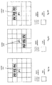
- Figure 4a represents the space and time predictors of the even frames used in the scanning mode of Figures 2 and 3,
- Figure 4b represents the space and time predictors of the odd frames used in the scanning mode of Figure 2,
- Figure 4c represents the space and time predictors of the odd frames used in the scanning mode of Figure 3.
- The description below is based on a motion estimation application. Other image processing operations can, of course, be considered and are included within the context of this invention. Among other exemplary embodiments, it is possible to imagine filtering, weighting, etc.
- An uninterlaced video signal Vin is received by a formatting means 4 before the signal is stored. These means 4 are designed to perform processing operations on the incoming video signal such as filtering, extraction and calculation of luminance or chrominance components.
A memory 3 is provided to store the converted video signal at the output of the means 4.
The memory 3 is preferably a fast-access SDRAM or DDRAM type memory. The memory 3 has enough capacity to store a number of video frames.
The memory 3 is connected to aninternal memory 2 with a capacity less than the memory 3 and intended to store at least one line of the current data frame and a line of the preceding data frame. Thismemory 2 is preferably implemented in the form of internal registers. It stores the line on which the current pixel is located and the number of lines needed to calculate the DFDs (displaced frame differences) from the current point. With the video being received in the left-right direction, when the scanning of the pixels for motion vector calculation is done from right to left, the line is stored in thememory 2 to be used subsequently in the space predictor calculation. - The
memory 2 also receives as input time information derived from the preceding frame and generated by a time projection module 5. This time information comprises the time predictors.
Amodule 1 calculates the motion vectors for each pixel of the current frame. This module receives as input the luminance value of the current pixel, and of the adjacent pixels on the current line and preceding line and the time and space predictors. - The direction of scanning of the frames, also called processing direction, is as defined in Figure 2.
The even frames are processed in the incoming direction of the video, the odd frames are processed in the other direction, the lines being processed from the first line of the frame to the last line of the frame. - This video processing retains the propagation from top to bottom of the information, but the reversal of the direction of scanning in every other image has two effects:
- reversal of scanning in the time recursive loop, the time and space predictors are derived from scans in opposite directions,
- reversal of scanning in the space recursive loop, the direction of calculation is reversed every image.
This enhances the accuracy of the processing by in no way favouring the left/right propagation of a conventional scan: the horizontal "average time scan" is zero. - Recurrence tends to propagate motion values in the direction of the scanning. This is reflected in a slight spatial offset of the motion values relative to the objects. Reversing the direction of calculation every other image limits this horizontal average offset.
- For each current pixel, a time predictor and three space predictors are calculated as indicated in Figures 4a and 4b.
- The position of the time predictor corresponds to the position of the current pixel represented by P1.
The space predictors are represented by P2, P3 and P4. - The
module 1 calculates the following function:
- In this motion estimation application, Res(Current_pixel) corresponds to the motion vector for the current pixel.
The function is applied for the luminance values.
For each current pixel, a DFD value is calculated, as is a gradient value, according to methods known to those skilled in the art. The best predictor is selected and the correction term is calculated based on the DFDs and the gradient so as to produce the motion vector at the output of themodule 1. - A time projection module 5 performs a time projection of the motion vector in the next frame. This time prediction is transmitted to the
memory 2 in order to be used when calculating the motion vectors of the pixels of the next frame.
Preferably, the order of choice of the best predictor is reversed from one frame to the next. If the DFD values match, the leftmost predictor is chosen for the even frames and the rightmost predictor is chosen for the odd frames. This also limits the favoured direction of convergence. This also offers a certain calculation time advantage because it is difficult to access the space predictor located on the same line as the current pixel. - Figure 3 represents an embodiment in which the scanning of the even frames and of the odd frames is also alternated, but in a way that is different from the scanning proposed in Figure 2. In practice, in this embodiment covered by the invention, the odd frames are scanned in the reverse direction of receipt of the video at line level and the processing of the lines begins with the last line of the frame to work back up to the first line.
The time and space predictors for this embodiment are as described in Figure 4c for the odd frames and Figure 4a for the even frames. - The invention also covers the embodiment in which the even frames are processed in the reverse direction of the video incoming direction, or from right to left, and the odd frames from left to right.
In other embodiments, the number of time and space predictors can be different according to the application or the video content.
In other embodiments, the video processing can be applied to the colour components of the video.
Claims (7)
- Method of scanning pixels in a sequence of images presenting a time recurrence, characterized in that the order of scanning of the pixels in one and the same line is reversed from one frame to the next.
- Method of scanning pixels according to Claim 1, characterized in that the order of scanning of the lines is reversed from one frame to the next.
- Method of estimating motion of a current frame relative to a reference frame, including the following steps for each pixel of the image:- estimation of space predictors,- estimation of time predictors,characterized in that the order of scanning of the pixels is in accordance with the method according to Claim 1 or 2, so as to obtain space and time predictors derived from scans in opposite directions.
- Method of estimating motion according to Claim 3, characterized in that, for each pixel, three space predictors and one time predictor are calculated.
- Device for scanning pixels in a sequence of images presenting a time recurrence, characterized in that the order of scanning of the pixels in one and the same line is reversed from one frame to the next.
- Device for estimating motion of a current frame relative to a reference frame, including:- means of estimating space predictors for each pixel of the image,- means of estimating time predictors for each pixel of the image,characterized in that the order of scanning of the pixels is in accordance with the method according to Claim 1 or 2, so as to obtain space and time predictors derived from scans in opposite directions.
- Device according to Claim 6, characterized in that the order of scanning of the lines is reversed from one frame to the next.
Applications Claiming Priority (1)
| Application Number | Priority Date | Filing Date | Title |
|---|---|---|---|
| FR0550345 | 2005-02-04 |
Publications (2)
| Publication Number | Publication Date |
|---|---|
| EP1689192A2 true EP1689192A2 (en) | 2006-08-09 |
| EP1689192A3 EP1689192A3 (en) | 2011-10-26 |
Family
ID=34954233
Family Applications (1)
| Application Number | Title | Priority Date | Filing Date |
|---|---|---|---|
| EP06100807A Withdrawn EP1689192A3 (en) | 2005-02-04 | 2006-01-25 | Method and device for scanning in a data frame |
Country Status (6)
| Country | Link |
|---|---|
| US (1) | US20060187355A1 (en) |
| EP (1) | EP1689192A3 (en) |
| JP (1) | JP4972321B2 (en) |
| KR (1) | KR20060089667A (en) |
| CN (1) | CN1816152B (en) |
| TW (1) | TW200630904A (en) |
Families Citing this family (1)
| Publication number | Priority date | Publication date | Assignee | Title |
|---|---|---|---|---|
| CN106534858B (en) * | 2015-09-10 | 2019-09-06 | 展讯通信(上海)有限公司 | Real motion estimation method and device |
Family Cites Families (8)
| Publication number | Priority date | Publication date | Assignee | Title |
|---|---|---|---|---|
| US4541116A (en) * | 1984-02-27 | 1985-09-10 | Environmental Research Institute Of Mi | Neighborhood image processing stage for implementing filtering operations |
| FR2648254B2 (en) * | 1988-09-23 | 1991-08-30 | Thomson Csf | METHOD AND DEVICE FOR ESTIMATING MOTION IN A SEQUENCE OF MOVED IMAGES |
| US5552824A (en) * | 1993-02-18 | 1996-09-03 | Lynx System Developers, Inc. | Line object scene generation apparatus |
| US5657077A (en) * | 1993-02-18 | 1997-08-12 | Deangelis; Douglas J. | Event recording system with digital line camera |
| US5517587A (en) * | 1994-09-23 | 1996-05-14 | International Business Machines Corporation | Positioning method and apparatus for line scanned images |
| JPH1184343A (en) * | 1997-09-01 | 1999-03-26 | Canon Inc | Image display device |
| JP2004266345A (en) * | 2003-02-05 | 2004-09-24 | Sony Corp | Video display method, video display processing device, video display system |
| US7471724B2 (en) * | 2003-06-23 | 2008-12-30 | Vichip Corp. Limited | Method and apparatus for adaptive multiple-dimensional signal sequences encoding/decoding |
-
2006
- 2006-01-25 EP EP06100807A patent/EP1689192A3/en not_active Withdrawn
- 2006-01-26 TW TW095102973A patent/TW200630904A/en unknown
- 2006-01-26 CN CN200610006978.4A patent/CN1816152B/en not_active Expired - Fee Related
- 2006-02-02 US US11/345,696 patent/US20060187355A1/en not_active Abandoned
- 2006-02-03 JP JP2006026904A patent/JP4972321B2/en not_active Expired - Fee Related
- 2006-02-03 KR KR1020060010601A patent/KR20060089667A/en not_active Ceased
Also Published As
| Publication number | Publication date |
|---|---|
| JP2006216052A (en) | 2006-08-17 |
| EP1689192A3 (en) | 2011-10-26 |
| KR20060089667A (en) | 2006-08-09 |
| TW200630904A (en) | 2006-09-01 |
| CN1816152A (en) | 2006-08-09 |
| JP4972321B2 (en) | 2012-07-11 |
| US20060187355A1 (en) | 2006-08-24 |
| CN1816152B (en) | 2010-09-08 |
Similar Documents
| Publication | Publication Date | Title |
|---|---|---|
| US7812884B2 (en) | Method and de-interlacing apparatus that employs recursively generated motion history maps | |
| KR100575116B1 (en) | Preprocessing process and devices for motion estimation | |
| US5784115A (en) | System and method for motion compensated de-interlacing of video frames | |
| KR101536794B1 (en) | Image interpolation with halo reduction | |
| EP1665808B1 (en) | Temporal interpolation of a pixel on basis of occlusion detection | |
| US20100201870A1 (en) | System and method for frame interpolation for a compressed video bitstream | |
| US8189105B2 (en) | Systems and methods of motion and edge adaptive processing including motion compensation features | |
| US20020146071A1 (en) | Scene change detection | |
| US20060222077A1 (en) | Method, apparatus and computer program product for generating interpolation frame | |
| KR100727795B1 (en) | Motion estimation | |
| WO2008152951A1 (en) | Method of and apparatus for frame rate conversion | |
| EP1489849A1 (en) | Adaptive block-based motion compensation | |
| US20020001347A1 (en) | Apparatus and method for converting to progressive scanning format | |
| US20070047651A1 (en) | Video prediction apparatus and method for multi-format codec and video encoding/decoding apparatus and method using the video prediction apparatus and method | |
| US7548655B2 (en) | Image still area determination device | |
| EP1430725A1 (en) | Image processor and image display apparatus provided with such image processor | |
| EP1474781A2 (en) | A method of and unit for estimating a motion vector of a group of pixels | |
| EP1592249A1 (en) | Reverse film mode extrapolation | |
| AU2004200237B2 (en) | Image processing apparatus with frame-rate conversion and method thereof | |
| US20060187355A1 (en) | Device and a method of scanning pixels in video frames | |
| KR100827214B1 (en) | Motion Compensation Upconversion for Video Scan Rate Conversion | |
| JP5448983B2 (en) | Resolution conversion apparatus and method, scanning line interpolation apparatus and method, and video display apparatus and method | |
| US20090041342A1 (en) | System and method for determining color value of pixel | |
| US20090148067A1 (en) | Image processing method and related apparatus for performing image processing operation according to image blocks in horizontal direction | |
| JP4354799B2 (en) | Interpolated image generation method and apparatus |
Legal Events
| Date | Code | Title | Description |
|---|---|---|---|
| PUAI | Public reference made under article 153(3) epc to a published international application that has entered the european phase |
Free format text: ORIGINAL CODE: 0009012 |
|
| AK | Designated contracting states |
Kind code of ref document: A2 Designated state(s): AT BE BG CH CY CZ DE DK EE ES FI FR GB GR HU IE IS IT LI LT LU LV MC NL PL PT RO SE SI SK TR |
|
| AX | Request for extension of the european patent |
Extension state: AL BA HR MK YU |
|
| RAP1 | Party data changed (applicant data changed or rights of an application transferred) |
Owner name: THOMSON LICENSING |
|
| PUAL | Search report despatched |
Free format text: ORIGINAL CODE: 0009013 |
|
| AK | Designated contracting states |
Kind code of ref document: A3 Designated state(s): AT BE BG CH CY CZ DE DK EE ES FI FR GB GR HU IE IS IT LI LT LU LV MC NL PL PT RO SE SI SK TR |
|
| AX | Request for extension of the european patent |
Extension state: AL BA HR MK YU |
|
| RIC1 | Information provided on ipc code assigned before grant |
Ipc: H04N 7/26 20060101AFI20110919BHEP |
|
| AKY | No designation fees paid | ||
| REG | Reference to a national code |
Ref country code: DE Ref legal event code: R108 |
|
| REG | Reference to a national code |
Ref country code: DE Ref legal event code: R108 Effective date: 20120704 |
|
| STAA | Information on the status of an ep patent application or granted ep patent |
Free format text: STATUS: THE APPLICATION IS DEEMED TO BE WITHDRAWN |
|
| 18D | Application deemed to be withdrawn |
Effective date: 20120427 |