EP1689003A1 - Piezoelectric actuator - Google Patents
Piezoelectric actuator Download PDFInfo
- Publication number
- EP1689003A1 EP1689003A1 EP05250603A EP05250603A EP1689003A1 EP 1689003 A1 EP1689003 A1 EP 1689003A1 EP 05250603 A EP05250603 A EP 05250603A EP 05250603 A EP05250603 A EP 05250603A EP 1689003 A1 EP1689003 A1 EP 1689003A1
- Authority
- EP
- European Patent Office
- Prior art keywords
- terminal
- piezoelectric actuator
- stack
- base portion
- body member
- Prior art date
- Legal status (The legal status is an assumption and is not a legal conclusion. Google has not performed a legal analysis and makes no representation as to the accuracy of the status listed.)
- Granted
Links
- 239000000446 fuel Substances 0.000 claims abstract description 38
- 238000009826 distribution Methods 0.000 claims abstract description 23
- 238000007789 sealing Methods 0.000 claims abstract description 13
- 230000005684 electric field Effects 0.000 claims abstract description 3
- 238000002347 injection Methods 0.000 claims description 5
- 239000007924 injection Substances 0.000 claims description 5
- 229910010293 ceramic material Inorganic materials 0.000 claims description 4
- 239000000463 material Substances 0.000 description 8
- 239000000919 ceramic Substances 0.000 description 6
- 238000002485 combustion reaction Methods 0.000 description 6
- 230000002706 hydrostatic effect Effects 0.000 description 5
- 230000008901 benefit Effects 0.000 description 4
- 239000004033 plastic Substances 0.000 description 4
- 229920003023 plastic Polymers 0.000 description 4
- 230000002411 adverse Effects 0.000 description 3
- 238000005219 brazing Methods 0.000 description 3
- 230000008602 contraction Effects 0.000 description 3
- 239000012530 fluid Substances 0.000 description 3
- 238000009434 installation Methods 0.000 description 3
- 230000013011 mating Effects 0.000 description 3
- 239000000126 substance Substances 0.000 description 3
- 230000007704 transition Effects 0.000 description 3
- XEEYBQQBJWHFJM-UHFFFAOYSA-N Iron Chemical compound [Fe] XEEYBQQBJWHFJM-UHFFFAOYSA-N 0.000 description 2
- PXHVJJICTQNCMI-UHFFFAOYSA-N Nickel Chemical compound [Ni] PXHVJJICTQNCMI-UHFFFAOYSA-N 0.000 description 2
- 229910045601 alloy Inorganic materials 0.000 description 2
- 239000000956 alloy Substances 0.000 description 2
- 238000005538 encapsulation Methods 0.000 description 2
- 238000000034 method Methods 0.000 description 2
- RYGMFSIKBFXOCR-UHFFFAOYSA-N Copper Chemical compound [Cu] RYGMFSIKBFXOCR-UHFFFAOYSA-N 0.000 description 1
- 229910001374 Invar Inorganic materials 0.000 description 1
- 239000000853 adhesive Substances 0.000 description 1
- 230000001070 adhesive effect Effects 0.000 description 1
- PNEYBMLMFCGWSK-UHFFFAOYSA-N aluminium oxide Inorganic materials [O-2].[O-2].[O-2].[Al+3].[Al+3] PNEYBMLMFCGWSK-UHFFFAOYSA-N 0.000 description 1
- 238000013459 approach Methods 0.000 description 1
- 230000015572 biosynthetic process Effects 0.000 description 1
- 230000008859 change Effects 0.000 description 1
- 230000002925 chemical effect Effects 0.000 description 1
- 238000004891 communication Methods 0.000 description 1
- 239000004020 conductor Substances 0.000 description 1
- 238000010276 construction Methods 0.000 description 1
- 229910052802 copper Inorganic materials 0.000 description 1
- 239000010949 copper Substances 0.000 description 1
- 230000003247 decreasing effect Effects 0.000 description 1
- 230000008021 deposition Effects 0.000 description 1
- 230000006866 deterioration Effects 0.000 description 1
- 238000005553 drilling Methods 0.000 description 1
- 230000000694 effects Effects 0.000 description 1
- 238000010292 electrical insulation Methods 0.000 description 1
- 238000005755 formation reaction Methods 0.000 description 1
- 238000010438 heat treatment Methods 0.000 description 1
- 230000001771 impaired effect Effects 0.000 description 1
- 230000006872 improvement Effects 0.000 description 1
- 229910001293 incoloy Inorganic materials 0.000 description 1
- 229910052742 iron Inorganic materials 0.000 description 1
- 229910000833 kovar Inorganic materials 0.000 description 1
- 238000004519 manufacturing process Methods 0.000 description 1
- 238000012986 modification Methods 0.000 description 1
- 230000004048 modification Effects 0.000 description 1
- 229910052759 nickel Inorganic materials 0.000 description 1
- 229920000642 polymer Polymers 0.000 description 1
- 238000007639 printing Methods 0.000 description 1
- 239000012858 resilient material Substances 0.000 description 1
- 230000007480 spreading Effects 0.000 description 1
- 238000003892 spreading Methods 0.000 description 1
Images





Classifications
-
- F—MECHANICAL ENGINEERING; LIGHTING; HEATING; WEAPONS; BLASTING
- F02—COMBUSTION ENGINES; HOT-GAS OR COMBUSTION-PRODUCT ENGINE PLANTS
- F02M—SUPPLYING COMBUSTION ENGINES IN GENERAL WITH COMBUSTIBLE MIXTURES OR CONSTITUENTS THEREOF
- F02M51/00—Fuel-injection apparatus characterised by being operated electrically
- F02M51/005—Arrangement of electrical wires and connections, e.g. wire harness, sockets, plugs; Arrangement of electronic control circuits in or on fuel injection apparatus
-
- H—ELECTRICITY
- H10—SEMICONDUCTOR DEVICES; ELECTRIC SOLID-STATE DEVICES NOT OTHERWISE PROVIDED FOR
- H10N—ELECTRIC SOLID-STATE DEVICES NOT OTHERWISE PROVIDED FOR
- H10N30/00—Piezoelectric or electrostrictive devices
- H10N30/80—Constructional details
- H10N30/87—Electrodes or interconnections, e.g. leads or terminals
- H10N30/875—Further connection or lead arrangements, e.g. flexible wiring boards, terminal pins
-
- H—ELECTRICITY
- H10—SEMICONDUCTOR DEVICES; ELECTRIC SOLID-STATE DEVICES NOT OTHERWISE PROVIDED FOR
- H10N—ELECTRIC SOLID-STATE DEVICES NOT OTHERWISE PROVIDED FOR
- H10N30/00—Piezoelectric or electrostrictive devices
- H10N30/80—Constructional details
- H10N30/88—Mounts; Supports; Enclosures; Casings
Definitions
- the present invention relates to a piezoelectric actuator and, particularly, to an electrical connector arrangement for a piezoelectric actuator of the type suitable for use in a fuel injector in an internal combustion engine.
- Automotive fuel injectors for delivering predetermined quantities of fuel into a combustion space of an internal combustion engine typically comprise a control piston which is operable to control the pressure of fuel contained within an injector control chamber.
- the control chamber is defined, in part, by a surface associated with an injector valve needle such that changes of fuel pressure within the control chamber cause movement of the valve needle into and out of engagement with an associated seating surface. As a result, delivery of pressurised fuel into the combustion space of the engine is controlled.
- Piezoelectric actuators used for this purpose are generally in the form of a stack body having a multi-layered laminated stack of piezoceramic elements or layers, each of which is separated by an electrically conductive layer.
- the electrically conductive layers act as internal electrode layers.
- the stack body is provided with positive and negative distribution electrodes arranged to establish electrical contact with the internal electrode layers.
- the distribution electrodes are connectable to a power supply and convey a voltage to the internal electrode layers.
- a piezoelectric actuator for use in a fuel injector, the actuator comprising a stack of one or more piezoelectric elements for receipt within an accumulator chamber of the injector, distribution electrode means for generating an electric field within the stack and an electrical connector arrangement.
- the electrical connector arrangement includes a body member defining an external boundary and including a base portion and a stem portion projecting from the base portion, wherein the base portion defines a base end face for abutment with an adjacent end face of the stack and terminal means for connection with an external power supply.
- the terminal means includes at least one terminal member disposed internal to the external boundary of the body member, wherein the at least one terminal member is connectable with an external power supply so as enable voltage supply to the distribution electrode means.
- the base portion of the body member further defines a sealing surface for abutment with a mating surface defined by the accumulator chamber, in use.
- the terminal means may include first and second terminal members which extend longitudinally through the body member, each of the first and second terminal members having a first end in electrical connection with a respective one of first and second terminal blades.
- the terminal means may include first and second contact plates, each of which is connected electrically to a second end of a respective one of the first and second terminal members.
- the distribution electrode means prefferably includes first and second distribution electrodes arranged one on either side of the stack and for each of the first and second contact plates to include a radially outer face connectable with an inner face of the first and second distribution electrodes.
- first ends of the terminal members are attached to an upper end face of the stem portion and each of the second ends of the terminal members is attached to a base end face of the base portion. Since the ends of the terminal members are attached to the body member only at respective end faces thereof, differential expansion and contraction between the body member and terminal members may be accommodated more readily so as to limit mechanical stresses and strains within the terminal members. Moreover, it is preferred that the terminal members and the body member are selected such that their coefficients of expansion are substantially the same in order to limit the extent of the stresses and strains still further.
- the base portion serves to support, insulate and protect the terminal members from the aggressive environment in which the actuator is used, whilst also providing a sealing surface engaging a mating surface defined by the accumulator chamber.
- the aforesaid functions often have been performed by distinct components.
- a shoulder region of the base portion defines the sealing surface.
- the body member is a unitary body of ceramic material.
- the overall length of the connector arrangement may be extended by the provision of an extension piece to accommodate at least one terminal member of greater length.
- the invention provides an electrical connector arrangement for use in the piezoelectric actuator as described above.
- the invention provides a fuel injector comprising an injector body having a nozzle body, secured at one end, the nozzle body defining a bore in which an injector valve needle is slidable to control fuel injection from outlet openings provided in the nozzle body wherein the injector body defines an accumulator chamber within which a piezoelectric actuator, as described above, is received.
- FIG. 1 shows a piezoelectric fuel injector 2 suitable for use within an internal combustion engine.
- the fuel injector 2 includes an injector body 4 having a first (upper) end defining an inlet 6 for connection to a source of pressurised fuel and a second (lower) end to which an injection nozzle body 8 is connected.
- the nozzle body 8 is provided with an axial bore 16 within which a valve needle 18 is slidable. It will be appreciated that the terms upper and lower are referred to in the context of the drawings and are not intended to limit any of the components thereby described to a specific orientation.
- the injector body 4 defines fuel passageways in the form of an inlet passage 10 and an accumulator volume or chamber 12.
- Fuel is supplied to the injector body 2 via the inlet 6 from a common rail or other appropriate source of pressurised fuel, which may also be arranged to supply fuel to one or more other injectors (not shown) of the engine.
- Pressurised fuel is conveyed from the inlet 6, through the inlet passage 10 and the accumulator volume 12, to an annular chamber 14 which forms part of the axial bore 16 defined by the nozzle body 8.
- the accumulator volume 12 houses a piezoelectric stack-type actuator (referred to generally as 20). Linear expansion and contraction of the actuator 20 is transmitted to the valve needle 18 via a control piston 22 which is attached, or coupled, to a first (lowermost) end of the actuator 20 and serves to control the volume, and therefore the pressure, of fuel within a control chamber 23. By controlling the pressure of fuel within the control chamber 23, the position of the control piston 22 controls whether or not fuel injection occurs through one or more nozzle outlets (not shown).
- the actuator 20 comprises a stack 24 of piezoelectric elements, each of which is separated by an internal electrode layer in a manner known in the art (the individual piezoelectric elements and the internal electrodes are not visible in Figure 1).
- the stack 24 is provided with a distribution electrode means in the form of positive and negative distribution electrodes 26a, 26b (only one of which is shown in Figure 1) that run longitudinally along opposing side faces of the stack 24 and make electrical contact with the internal electrodes of the stack 24.
- An electrical connector arrangement or module 30 is located at the ceiling, or upper end, of the accumulator volume 12 and extends through a longitudinal drilling or channel 41 provided in the injector body 4.
- the module includes a terminal means having a pair of positive and negative terminal blades 32, 34 which project away from the connector module 30 to reside in a lateral recess 42 provided in the injector body 4.
- the terminal blades 32, 34 provide a convenient fixture point for an external power supply plug and serve to convey an applied voltage to the distribution electrodes 26a, 26b, and thus to the internal stack electrodes, via the connector module 30.
- the length of the stack 24 can be increased or decreased thereby to control the axial position of the control piston 22 and, thus, the pressure within the control chamber 23.
- the connector module 30 includes a module body member 36 comprising a base portion 36a in the form of a block which tapers into a generally cylindrical stem portion 36b and so defines an annular shoulder region 36c therebetween.
- the annular shoulder region 36c serves as a sealing surface which engages the opening 41 to prevent the escape of pressurised fuel from the accumulator volume 12, as will be described in greater detail later.
- the connector module 30 is preferably formed from a ceramic material such as high grade alumina in order to withstand the aggressive environment within which it is located. However, the connector module may be formed from a less resilient material if conditions permit.
- the base portion 36a of the body member 36 defines a substantially flat, base end face 31 of the module 30 and the stem portion 36b defines an upper end face 33 of the module 30.
- the terminal means of the module 30 includes first and second terminal members, which take the form of positive and negative terminal pins 38a, 38b, that extend longitudinally through the module 30 to terminate in the terminal blades 32, 34 which project from the upper end face 33.
- the terminal pins 38a, 38b are arranged such that first ends of the terminal pins 38a, 38b terminate at the upper end face 33 of the module 30 and second ends of the terminal pins 38a, 38b terminate at the base end face 31 of the module 30.
- the ends of the terminal pins 38a, 38b are fixed to their respective end faces 31, 33 by metallised regions, of which only the metallised regions 37a, 37b on the upper end face 33 of the module 30 are shown in the Figures.
- the metallised regions 37a, 37b are separated by a cross-channel 35 that serves to guard against electrical arcing between the terminal blades 32, 34.
- the metallised regions 37a, 37b may be formed by such techniques as ink printing, vapour deposition or brazing, for example.
- the positive and negative terminal blades 32, 34 extend upwardly from the upper face of the stem portion 36b and are affixed to their corresponding metallised regions 37a, 37b by brazing or an equivalent technique such that a high strength contact is achieved.
- terminal pins 38a, 38b are fixed to the body member 36 at, or in the region of, its upper and lower end faces 31, 33, most of the outer surface of each terminal pin 38a, 38b is not in fixed contact with the connector module 30.
- the differential expansion between the body member 36 and the terminal pins 38a, 38b may more readily be absorbed.
- the material from which the terminal pins 38a, 38b are formed is selected such that its coefficient of expansion is substantially the same as that of the ceramic material of the connector module 30.
- tensile or compressive forces exerted on the terminal pins 38a, 38b are limited.
- the terminal pins 38a, 38b are formed from a low expansion alloy such as KOVAR (RTM) although it should be appreciated that other materials that exhibit the appropriate chemical and electrical properties may also be used to form the terminal pins 38a, 38b.
- the base end face 31 of the module 30 is shaped to define first and second recesses 39, of rectilinear form, which receive correspondingly shaped metallic contact plates 40a, 40b.
- Each contact plate 40a, 40b defines a hole through which a respective terminal pin 38a, 38b may extend, thereby electrically connecting the contact plates 40a, 40b to the terminal blades 32, 34 via the terminal pins 38a, 38b. It will be appreciated, therefore, that the terminal blades 32, 34, terminal pins 38a, 38b and contact plates 40a, 40b together form the terminal means of the connector module 30 and provide positive and negative conductor paths from an external power supply to a respective distribution electrode 26a, 26b of the stack 24.
- the contact plates 40a, 40b are arranged such that a radially outer face thereof lies flush with a radially outer face of the base portion 36a of the body member 36.
- the contact plates 40a, 40b are formed from an alloy comprising iron, nickel and copper, although it should be appreciated that other suitable materials may also be used. Proprietary materials are available for this purpose, for example INVAR (RTM), COVAR (RTM) and INCOLOY (RTM).
- the base end face 31 of the base portion 36a is located adjacent to, and abuts against, a substantially flat upper end face of the stack 24.
- the base portion 36a is shaped so that its boundary profile, or "outer envelope", substantially matches that of the upper end face of the stack 24 and, as a result, there is no significant geometric transition between the stack 24 and the connector module 30.
- the first and second distribution electrodes 26a, 26b are permitted to extend upward beyond the end face of the stack 24 such that their inner facing surfaces make contact with the radially outer faces of the contact plates 40a, 40b.
- An advantage of this arrangement, particularly when the connector module 30 is used for a piezoelectric actuator of the type described, is that the contact plates 40a, 40b provide a rigid contact surface for the distribution electrodes 26a, 26b. This is a marked improvement over previously proposed designs in which contact between the connector terminals and the distribution electrodes occurs at a point along the stack side face with connector terminals extending over and around the upper face of the stack and onto the stack sides for connection with the distribution electrodes.
- Figure 8 shows in detail the actuator 20 (comprising the stack 24 and the connector module 30) installed within the accumulator volume 12 and the sealing interface that the connector module 30 establishes with the injector body 4.
- the stem portion 36b of the module 30 extends through the longitudinal channel 41, which communicates with the accumulator volume 12, such that the terminal blades 32, 34 protrude into the lateral recess 42 through the open, upper end of the channel 41.
- the lateral recess 42 constitutes a connector socket for receiving a wiring harness connector (not shown), by which means the actuator 20 is connected to the external power supply.
- the stem region 36b is received within the channel 41 to such an extent that the annular shoulder region 36c of the module 30 engages an internal mating surface 44 of the accumulator volume 12 in the region of communication between the lower end of the longitudinal channel 41 and the accumulator volume 12.
- the internal surface 44 is substantially frustoconical in order to provide a uniform surface with which the shoulder region 36c of the connector module 30 engages. This ensures that a substantially fluid tight seal is established, in use, against the egress of high pressure fluid.
- the sealing function of the connector module 30 is improved rather than impaired by the hydrostatic forces acting on the actuator 20 and, hence, a substantially leak-proof installation is achieved.
- the actuator 20 Since the actuator 20 is disposed within an accumulator volume filled with high pressure fuel, it is necessary to protect the actuator 20 against deterioration. To this end the actuator is largely enveloped within a polymeric sleeve for the purposes of electrical insulation and chemical protection.
- the encapsulation sleeve is not shown in Figure 8 for the purpose of clarity, the sleeve extends along the entire length of the stack 24, up onto the base 36a of the connector module 36. It is permissible for the encapsulation sleeve to extend onto the shoulder region 36c provided it does not interfere with the point of sealing contact between the module 30 and the wall of the accumulator volume 12.
- the shoulder region 36c includes a first, upper seating region 52 of frustoconical form and a second, lower seating region 54, at least partly of frustoconical form, but which transitions into a radiused surface.
- first seating region 52 may also be partly of frustoconical form.
- the mutual interface of the upper seating region 52 and the lower seating region 54 defines a seating line 56 which engages the internal surface 44 when the actuator 20 is installed within the accumulator volume 12 of the injector 2.
- a seating line 56 to engage the internal surface increases the efficacy of the seal achieved by the module 30 since the hydrostatic force acting on the actuator 20, in use, is concentrated at a narrow margin instead of spreading the applied force over a relatively large seating region which could adversely affect the sealing properties of the module.
- the seating line 56 may be arranged to deform, in use, such that the module 30 "beds in” over the seating line 56 so as to take account of eccentricities in either the internal surface 44 or the seating line 56.
- the connector module 30 is a unitary component and the ceramic body member 36 is shaped as necessary during manufacture to optimise the sealing characteristics of the connector module 30 for a particular application.
- the channel 41 within which the stem portion 36b of the connector module 30 is received is too long for the connector module 30 to be manufactured as a single part.
- a connector module 60 is formed from a body member 62 and an extension piece 64 mounted thereon. It will be appreciated that the configuration of the base member 62 in Figure 10a and 10b is substantially the same as the body member 36 of the previous embodiment so it will not be described again in detail here.
- the body member 62 is provided with terminal means including first and second terminal pins 66a, 66b extending longitudinally therethrough.
- the terminal pins 66a, 66b have opposite ends terminating at respective upper and lower end faces 61, 63 of the body member 62.
- terminal pins 68a, 68b extend longitudinally through the extension piece 64 and terminate at its upper and lower end faces 65, 67.
- the ends of the terminal pins 66a, 66b; 68a, 68b are affixed to the associated end faces 61, 63; 65, 67 of the body member 62, or the extension piece 64 by metallised regions (not shown).
- the lower end face 65 of the extension piece 64 is fixedly mounted on the body member 62, for example by brazing. Electrical connection is therefore established between the terminal pins 66a, 66b of the body member 62 and the terminal pins 68a, 68b of the extension piece 64. Correct alignment of the body member 62 and the extension piece 64 may be ensured by the provision of a projection 72 on the extension piece 64 and a corresponding recess 74 on the face 61 of the body member 62. Other suitable complimentary formations may also be provided for this purpose.
- terminal blades 70a, 70b, forming part of the terminal means are brazed or otherwise attached to the upper end face 67 of the extension piece 64.
- the overall length of the connector module may be increased to suit a particular injector installation without compromising the structural rigidity that would likely occur if such an extended connector module 60 was manufactured as a single ceramic-bodied part.
- terminal pins 66a, 66b; 68a, 68b are described as relatively short separate sections which are joined, or electrically connected, at the junction between the base member 62 and the extension piece 64, it should be understood that each terminal may alternatively be formed from a single, relatively long member that extends along the entire length of the extended module 60.
- the base member 36a of the module 30 is a separate part to the stem region 36b.
- the base member 36a terminates at the shoulder region 36c and a recess 80 in the upper end face of the base region defines a pocket within which the stem region 36b is received and secured thereto by a suitable adhesive. Forming the module 30 in this way avoids stresses that occur at the transition between the base member 36a and the stem region 36b when they are formed as a unitary part.
- the base member 36a is of ceramic form, it is resistant to the high pressures and temperatures within the fuel accumulator volume 12 as well as being resistant to chemical attack.
- the stem region 36b may also be formed from ceramic. However, it is possible to form the stem region 36b from an alternative material, for example plastics, if desired. It should also be appreciated that the base member 36a itself may be formed from a material other than ceramic if the environment in which it is located permits. However, a base member 36a of ceramic form is preferred when used within fuel injection equipment.
- terminal pins 38a, 38b described with reference to previous embodiments are not limited to having a "rod-like" or “wire” form and may also be stamped or otherwise formed from metallic sheet material. Although rod-like terminal pins may be more suitable to insert through drilled ceramic components, stamped terminal pins may be more readily shaped for inclusion within a plastics overmoulded stem region.
- the connector module 30 has been described as including terminal blades 32, 34, terminal pins 38a, 38b, and contact plates 40a, 40b all of positive and negative polarity
- the invention is also applicable to a connector module that is arranged such that a single terminal member extends through the body member 36, 62 and terminates at a single contact plate for connection to a suitable component.
- the invention is also applicable to a connector module that is provided with three or more terminal blades, terminal pins and contact plates if a particular application so requires.
Landscapes
- Engineering & Computer Science (AREA)
- Chemical & Material Sciences (AREA)
- Combustion & Propulsion (AREA)
- Mechanical Engineering (AREA)
- General Engineering & Computer Science (AREA)
- Fuel-Injection Apparatus (AREA)
- Electrically Driven Valve-Operating Means (AREA)
- Coupling Device And Connection With Printed Circuit (AREA)
Abstract
Description
- The present invention relates to a piezoelectric actuator and, particularly, to an electrical connector arrangement for a piezoelectric actuator of the type suitable for use in a fuel injector in an internal combustion engine.
- Automotive fuel injectors for delivering predetermined quantities of fuel into a combustion space of an internal combustion engine typically comprise a control piston which is operable to control the pressure of fuel contained within an injector control chamber. The control chamber is defined, in part, by a surface associated with an injector valve needle such that changes of fuel pressure within the control chamber cause movement of the valve needle into and out of engagement with an associated seating surface. As a result, delivery of pressurised fuel into the combustion space of the engine is controlled.
- It is known to provide a fuel injector with a piezoelectric actuator to control movement of the control piston. Piezoelectric actuators used for this purpose are generally in the form of a stack body having a multi-layered laminated stack of piezoceramic elements or layers, each of which is separated by an electrically conductive layer. The electrically conductive layers act as internal electrode layers. The stack body is provided with positive and negative distribution electrodes arranged to establish electrical contact with the internal electrode layers. The distribution electrodes are connectable to a power supply and convey a voltage to the internal electrode layers.
- Application of a voltage across the internal electrodes causes expansion and contraction of the stack corresponding to the magnitude and the polarity of the applied voltage. The change in length of the stack is used to control movement of the control piston and thus opening and closing of the valve needle.
- It is known that the application of a compressive force to a piezoelectric stack influences beneficially its performance and durability. In the case of piezoelectrically operable fuel injectors for use in compression-ignition internal combustion engines, a known approach is to locate the piezoelectric stack within a fuel-filled accumulator volume or chamber. Typically, fuel within the accumulator volume is maintained at pressures of up to 2000 bar and so the piezoelectric stack experiences a high compressive loading due to hydrostatic forces. An actuator of this type is exemplified in EP0995901. Enveloping the stack within a polymer casing or sleeve guards against ingress of high pressure fuel into the stack structure.
- Although locating the piezoelectric actuator in a high pressure fluid environment has its associated advantages, it is necessary to ensure that the electrical connections to the stack are adequately and reliably sealed from high pressure fuel within the accumulator volume. It is also vital that the high hydrostatic forces or the aggressive chemical effects of the fuel-laden environment do not adversely affect the provisions for sealing or insulating the stack.
- It is an object of the present invention to provide an electrical connector arrangement that addresses these concerns.
- In accordance with a first aspect of the present invention, there is provided a piezoelectric actuator for use in a fuel injector, the actuator comprising a stack of one or more piezoelectric elements for receipt within an accumulator chamber of the injector, distribution electrode means for generating an electric field within the stack and an electrical connector arrangement. The electrical connector arrangement includes a body member defining an external boundary and including a base portion and a stem portion projecting from the base portion, wherein the base portion defines a base end face for abutment with an adjacent end face of the stack and terminal means for connection with an external power supply. The terminal means includes at least one terminal member disposed internal to the external boundary of the body member, wherein the at least one terminal member is connectable with an external power supply so as enable voltage supply to the distribution electrode means. The base portion of the body member further defines a sealing surface for abutment with a mating surface defined by the accumulator chamber, in use.
- Preferably, the terminal means may include first and second terminal members which extend longitudinally through the body member, each of the first and second terminal members having a first end in electrical connection with a respective one of first and second terminal blades. Furthermore, the terminal means may include first and second contact plates, each of which is connected electrically to a second end of a respective one of the first and second terminal members.
- It is preferable for the distribution electrode means to include first and second distribution electrodes arranged one on either side of the stack and for each of the first and second contact plates to include a radially outer face connectable with an inner face of the first and second distribution electrodes.
- Due the problems created by locating the actuator within a high temperature and high pressure environment, in use, it is preferable that first ends of the terminal members are attached to an upper end face of the stem portion and each of the second ends of the terminal members is attached to a base end face of the base portion. Since the ends of the terminal members are attached to the body member only at respective end faces thereof, differential expansion and contraction between the body member and terminal members may be accommodated more readily so as to limit mechanical stresses and strains within the terminal members. Moreover, it is preferred that the terminal members and the body member are selected such that their coefficients of expansion are substantially the same in order to limit the extent of the stresses and strains still further.
- A particular advantage of the invention is that the base portion serves to support, insulate and protect the terminal members from the aggressive environment in which the actuator is used, whilst also providing a sealing surface engaging a mating surface defined by the accumulator chamber. In existing designs, the aforesaid functions often have been performed by distinct components. Preferably, a shoulder region of the base portion defines the sealing surface. Moreover, it is preferred that the body member is a unitary body of ceramic material.
- In an alternative embodiment, the overall length of the connector arrangement may be extended by the provision of an extension piece to accommodate at least one terminal member of greater length. Through the addition of one or more extension pieces to the body member, the flexibility of the connector arrangement to suit a particular application is improved.
- In another aspect, the invention provides an electrical connector arrangement for use in the piezoelectric actuator as described above.
- In yet another aspect, the invention provides a fuel injector comprising an injector body having a nozzle body, secured at one end, the nozzle body defining a bore in which an injector valve needle is slidable to control fuel injection from outlet openings provided in the nozzle body wherein the injector body defines an accumulator chamber within which a piezoelectric actuator, as described above, is received.
- It should be noted that the preferred features as defined above are applicable to each aspect of the invention.
- So that it may be more readily understood, the present invention will now be described, by way of example only, with reference to the accompanying drawings in which:
- Figure 1 is a sectional view of a fuel injector having a piezoelectric actuator incorporating the connector arrangement of the present invention;
- Figure 2 is an enlarged perspective view, from above, of the connector arrangement in Figure 1;
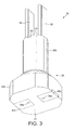
- Figure 3 is an enlarged perspective view, from below, of the connector arrangement in Figure 1;
- Figure 4 is a sectional view of the connector arrangement in Figures 1 to 3;
- Figure 5 is a side view of the connector arrangement when mounted on a stack-type piezoelectric actuator;
- Figure 6 is a sectional view of the connector arrangement and piezoelectric actuator in Figure 5;
- Figure 7 is a perspective view of the connector arrangement when mounted on a stack-type piezoelectric actuator;
- Figure 8 is an enlarged part-sectional view of the piezoelectric actuator as shown in Figure 7 when installed within an injector accumulator volume;
- Figure 9 is a further enlarged part-sectional view of the piezoelectric actuator when installed within an injector accumulator volume, as shown in Figure 8;
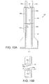
- Figures 10a and 10b show an alternative embodiment of the invention; and
- Figure 11 shows a further embodiment of the invention.
- Figure 1 shows a
piezoelectric fuel injector 2 suitable for use within an internal combustion engine. Thefuel injector 2 includes aninjector body 4 having a first (upper) end defining aninlet 6 for connection to a source of pressurised fuel and a second (lower) end to which aninjection nozzle body 8 is connected. Thenozzle body 8 is provided with anaxial bore 16 within which avalve needle 18 is slidable. It will be appreciated that the terms upper and lower are referred to in the context of the drawings and are not intended to limit any of the components thereby described to a specific orientation. Between its ends, theinjector body 4 defines fuel passageways in the form of aninlet passage 10 and an accumulator volume orchamber 12. - Fuel is supplied to the
injector body 2 via theinlet 6 from a common rail or other appropriate source of pressurised fuel, which may also be arranged to supply fuel to one or more other injectors (not shown) of the engine. Pressurised fuel is conveyed from theinlet 6, through theinlet passage 10 and theaccumulator volume 12, to anannular chamber 14 which forms part of theaxial bore 16 defined by thenozzle body 8. - The
accumulator volume 12 houses a piezoelectric stack-type actuator (referred to generally as 20). Linear expansion and contraction of theactuator 20 is transmitted to thevalve needle 18 via acontrol piston 22 which is attached, or coupled, to a first (lowermost) end of theactuator 20 and serves to control the volume, and therefore the pressure, of fuel within acontrol chamber 23. By controlling the pressure of fuel within thecontrol chamber 23, the position of thecontrol piston 22 controls whether or not fuel injection occurs through one or more nozzle outlets (not shown). - The
actuator 20 comprises astack 24 of piezoelectric elements, each of which is separated by an internal electrode layer in a manner known in the art (the individual piezoelectric elements and the internal electrodes are not visible in Figure 1). Thestack 24 is provided with a distribution electrode means in the form of positive andnegative distribution electrodes stack 24 and make electrical contact with the internal electrodes of thestack 24. - An electrical connector arrangement or
module 30 is located at the ceiling, or upper end, of theaccumulator volume 12 and extends through a longitudinal drilling orchannel 41 provided in theinjector body 4. Although Figure 1 does not show theconnector module 30 in detail, it can be seen that the module includes a terminal means having a pair of positive andnegative terminal blades connector module 30 to reside in alateral recess 42 provided in theinjector body 4. Theterminal blades distribution electrodes connector module 30. By controlling the applied voltage, the length of thestack 24 can be increased or decreased thereby to control the axial position of thecontrol piston 22 and, thus, the pressure within thecontrol chamber 23. - The
connector module 30 of Figure 1 will now be described in greater detail. Referring to Figures 2 to 4, theconnector module 30 includes amodule body member 36 comprising abase portion 36a in the form of a block which tapers into a generallycylindrical stem portion 36b and so defines anannular shoulder region 36c therebetween. Theannular shoulder region 36c serves as a sealing surface which engages theopening 41 to prevent the escape of pressurised fuel from theaccumulator volume 12, as will be described in greater detail later. Theconnector module 30 is preferably formed from a ceramic material such as high grade alumina in order to withstand the aggressive environment within which it is located. However, the connector module may be formed from a less resilient material if conditions permit. - The
base portion 36a of thebody member 36 defines a substantially flat,base end face 31 of themodule 30 and thestem portion 36b defines an upper end face 33 of themodule 30. The terminal means of themodule 30 includes first and second terminal members, which take the form of positive and negativeterminal pins module 30 to terminate in theterminal blades upper end face 33. The terminal pins 38a, 38b are arranged such that first ends of theterminal pins module 30 and second ends of theterminal pins base end face 31 of themodule 30. The ends of theterminal pins regions module 30 are shown in the Figures. Themetallised regions terminal blades metallised regions terminal blades stem portion 36b and are affixed to their correspondingmetallised regions - Since the
terminal pins body member 36 at, or in the region of, its upper and lower end faces 31, 33, most of the outer surface of eachterminal pin connector module 30. As a result, the differential expansion between thebody member 36 and theterminal pins terminal pins connector module 30. As a result, tensile or compressive forces exerted on theterminal pins terminal pins terminal pins - With specific reference to Figures 3 and 4, the
base end face 31 of themodule 30 is shaped to define first and second recesses 39, of rectilinear form, which receive correspondingly shapedmetallic contact plates contact plate terminal pin contact plates terminal blades terminal pins terminal blades terminal pins contact plates connector module 30 and provide positive and negative conductor paths from an external power supply to arespective distribution electrode stack 24. Thecontact plates base portion 36a of thebody member 36. In this embodiment, thecontact plates - Referring now to Figures 5 to 7, when the
connector module 30 is mounted on and bonded to thestack 24, thebase end face 31 of thebase portion 36a is located adjacent to, and abuts against, a substantially flat upper end face of thestack 24. Moreover, thebase portion 36a is shaped so that its boundary profile, or "outer envelope", substantially matches that of the upper end face of thestack 24 and, as a result, there is no significant geometric transition between thestack 24 and theconnector module 30. Once thestack 24 and theconnector module 30 are assembled together, they are received within theaccumulator volume 12, which contains high pressure fuel, in use. Therefore, a particular advantage of the invention is that since the cross section of thebase portion 36a is configured to be comparable with that of thestack 24, the adverse effects of high hydrostatic forces are avoided. In addition the exposure of relatively low-strength materials (e.g. overmoulded plastics parts) to high pressure fuel is avoided. In previous proposed designs, connector module edges of plastics construction overhang the boundary of thestack 24 such that high pressure fuel exerts a force on the connector module that, over time, may lead to injector failure due to the connector module becoming detached from thestack 24. In the present invention, there is no overhang of thestack 24 by theconnector module 30 so the problem is avoided. - As the profile of the
base portion 36b is comparable to that of thestack 24, the first andsecond distribution electrodes stack 24 such that their inner facing surfaces make contact with the radially outer faces of thecontact plates connector module 30 is used for a piezoelectric actuator of the type described, is that thecontact plates distribution electrodes - Figure 8 shows in detail the actuator 20 (comprising the
stack 24 and the connector module 30) installed within theaccumulator volume 12 and the sealing interface that theconnector module 30 establishes with theinjector body 4. When theactuator 20 is installed within theaccumulator volume 12 of theinjector 2, thestem portion 36b of themodule 30 extends through thelongitudinal channel 41, which communicates with theaccumulator volume 12, such that theterminal blades lateral recess 42 through the open, upper end of thechannel 41. Thelateral recess 42 constitutes a connector socket for receiving a wiring harness connector (not shown), by which means theactuator 20 is connected to the external power supply. Thestem region 36b is received within thechannel 41 to such an extent that theannular shoulder region 36c of themodule 30 engages aninternal mating surface 44 of theaccumulator volume 12 in the region of communication between the lower end of thelongitudinal channel 41 and theaccumulator volume 12. Theinternal surface 44 is substantially frustoconical in order to provide a uniform surface with which theshoulder region 36c of theconnector module 30 engages. This ensures that a substantially fluid tight seal is established, in use, against the egress of high pressure fluid. The sealing function of theconnector module 30 is improved rather than impaired by the hydrostatic forces acting on theactuator 20 and, hence, a substantially leak-proof installation is achieved. - Since the
actuator 20 is disposed within an accumulator volume filled with high pressure fuel, it is necessary to protect theactuator 20 against deterioration. To this end the actuator is largely enveloped within a polymeric sleeve for the purposes of electrical insulation and chemical protection. Although the encapsulation sleeve is not shown in Figure 8 for the purpose of clarity, the sleeve extends along the entire length of thestack 24, up onto thebase 36a of theconnector module 36. It is permissible for the encapsulation sleeve to extend onto theshoulder region 36c provided it does not interfere with the point of sealing contact between themodule 30 and the wall of theaccumulator volume 12. - As shown more clearly in Figure 9, the
shoulder region 36c includes a first,upper seating region 52 of frustoconical form and a second,lower seating region 54, at least partly of frustoconical form, but which transitions into a radiused surface. It should be appreciated that thefirst seating region 52 may also be partly of frustoconical form. The mutual interface of theupper seating region 52 and thelower seating region 54 defines aseating line 56 which engages theinternal surface 44 when theactuator 20 is installed within theaccumulator volume 12 of theinjector 2. The use of aseating line 56 to engage the internal surface increases the efficacy of the seal achieved by themodule 30 since the hydrostatic force acting on theactuator 20, in use, is concentrated at a narrow margin instead of spreading the applied force over a relatively large seating region which could adversely affect the sealing properties of the module. Further, theseating line 56 may be arranged to deform, in use, such that themodule 30 "beds in" over theseating line 56 so as to take account of eccentricities in either theinternal surface 44 or theseating line 56. - In this embodiment, the
connector module 30 is a unitary component and theceramic body member 36 is shaped as necessary during manufacture to optimise the sealing characteristics of theconnector module 30 for a particular application. However, it is possible that, due to a particular installation, thechannel 41 within which thestem portion 36b of theconnector module 30 is received is too long for theconnector module 30 to be manufactured as a single part. This particular scenario is addressed in an alternative embodiment of the invention, as illustrated in Figures 10a and 10b, in which aconnector module 60 is formed from abody member 62 and anextension piece 64 mounted thereon. It will be appreciated that the configuration of thebase member 62 in Figure 10a and 10b is substantially the same as thebody member 36 of the previous embodiment so it will not be described again in detail here. - As in the previously described embodiment, the
body member 62 is provided with terminal means including first and secondterminal pins body member 62. In a similar manner,terminal pins extension piece 64 and terminate at its upper and lower end faces 65, 67. The ends of theterminal pins body member 62, or theextension piece 64 by metallised regions (not shown). - In order to assemble the
connector module 60, thelower end face 65 of theextension piece 64 is fixedly mounted on thebody member 62, for example by brazing. Electrical connection is therefore established between theterminal pins body member 62 and theterminal pins extension piece 64. Correct alignment of thebody member 62 and theextension piece 64 may be ensured by the provision of aprojection 72 on theextension piece 64 and acorresponding recess 74 on theface 61 of thebody member 62. Other suitable complimentary formations may also be provided for this purpose. To complete theconnector module 60,terminal blades extension piece 64. - As a result of the arrangement described above, the overall length of the connector module may be increased to suit a particular injector installation without compromising the structural rigidity that would likely occur if such an
extended connector module 60 was manufactured as a single ceramic-bodied part. - Although the
terminal pins base member 62 and theextension piece 64, it should be understood that each terminal may alternatively be formed from a single, relatively long member that extends along the entire length of theextended module 60. - Another alternative embodiment is shown in Figure 11, where like parts are denoted by like reference numerals. In this embodiment, the
base member 36a of themodule 30 is a separate part to thestem region 36b. Thebase member 36a terminates at theshoulder region 36c and arecess 80 in the upper end face of the base region defines a pocket within which thestem region 36b is received and secured thereto by a suitable adhesive. Forming themodule 30 in this way avoids stresses that occur at the transition between thebase member 36a and thestem region 36b when they are formed as a unitary part. - Since the
base member 36a is of ceramic form, it is resistant to the high pressures and temperatures within thefuel accumulator volume 12 as well as being resistant to chemical attack. Thestem region 36b may also be formed from ceramic. However, it is possible to form thestem region 36b from an alternative material, for example plastics, if desired. It should also be appreciated that thebase member 36a itself may be formed from a material other than ceramic if the environment in which it is located permits. However, abase member 36a of ceramic form is preferred when used within fuel injection equipment. - The terminal pins 38a, 38b described with reference to previous embodiments are not limited to having a "rod-like" or "wire" form and may also be stamped or otherwise formed from metallic sheet material. Although rod-like terminal pins may be more suitable to insert through drilled ceramic components, stamped terminal pins may be more readily shaped for inclusion within a plastics overmoulded stem region.
- Having described particular preferred embodiments of the present invention, it is to be appreciated that the embodiments referred to are exemplary only and that variations and modifications may be made without departing from the scope of the invention as set forth in the appended claims.
- For example, although in this description, the
connector module 30 has been described as includingterminal blades terminal pins contact plates body member
Claims (14)
- A piezoelectric actuator (20) for use in a fuel injector, the actuator (20) comprising:a stack (24) of one or more piezoelectric elements for receipt within an accumulator chamber (12) of the injector;distribution electrode means (26a, 26b) for generating an electric field within the stack (24);an electrical connector arrangement (30) including a body member (36) defining an external boundary and including a base portion (36a) and a stem portion (36b) projecting from the base portion (36a), wherein the base portion (36a) defines a base end face (31) for abutment with an adjacent end face of the stack (24); andterminal means for connection with an external power supply, the terminal means including at least one terminal member (38a, 38b) disposed internal to the external boundary of the body member (36), wherein the at least one terminal member (38a, 38b) is connectable with an external power supply so as enable voltage supply to the distribution electrode means (26a, 26b) and wherein the base portion (36a) further defines a sealing surface for abutment with an internal surface (44) defined by the accumulator chamber (12).
- The piezoelectric actuator (20) as claimed in Claim 1, wherein the terminal means includes first and second terminal members (38a, 38b) which extend longitudinally through the body member (36), each of the first and second terminal members (38a, 38b) having a first end in electrical connection with a respective one of the first and second terminal blades (32, 34).
- The piezoelectric actuator (20) as claimed in Claim 2, the terminal means further including first and second contact plates (40a, 40b), each of which is connected electrically to a second end of a respective one of the first and second terminal members (38a, 38b).
- The piezoelectric actuator (20) as claimed in Claim 3, wherein the distribution electrode means includes first and second distribution electrodes (26a, 26b) arranged one on either side of the stack (24) and wherein each of the first and second contact plates (40a, 40b) is connectable with a respective one of the first and second distribution electrodes (26a, 26b).
- The piezoelectric actuator (20) as claimed in Claim 4, wherein the first and second contact plates (40a, 40b) include a radially outer face for contacting an inner surface of the first and second distribution electrodes (26a, 26b).
- The piezoelectric actuator (20) as claimed in any one of Claims 2 to 5, wherein each of the first ends of the at least one terminal member (28a, 28b) is attached to an upper end face (33) of the stem portion (36b) and each of the second ends of the terminal members (28a, 28b) is attached to a base end face (31) of the base portion (36a).
- The piezoelectric actuator (20) as claimed in any one of Claims 1 to 6, wherein the sealing surface is defined by a shoulder region (36c) of the base portion (36a).
- The piezoelectric actuator (20) as claimed in Claim 7, wherein the shoulder region (36c) includes a first seating region (52) and a second seating region (54) whereby a mutual interface between the first and second seating regions (52, 54) defines a seating line (56) for engagement with the internal surface (44).
- The piezoelectric actuator (20) as claimed in any one of Claims 1 to 8, wherein the terminal members (38a, 38b) and the body member (36) are selected such that their coefficients of expansion are substantially the same.
- The piezoelectric actuator (20) as claimed in any one of Claims 1 to 9, wherein the body member (36) is a unitary body of ceramic material.
- The piezoelectric actuator (20) as claimed in any one of Claims 1 to 9, wherein the base portion (36a) and the stem portion (36b) are separate and distinct parts.
- The piezoelectric actuator (20) as claimed in any one of Claims 1 to 11, wherein the body member (36, 62) is provided with an extension piece (64) to extend the overall length available to accommodate the at least one terminal member (38a, 38b).
- An electrical connector arrangement (30) for use in the piezoelectric actuator (20) of any one of Claims 1 to 12.
- A fuel injector comprising an injector body (4) having a nozzle body (8) secured at one end, the nozzle body (8) defining a bore (16) in which an injector valve needle (18) is slidable to control fuel injection from outlet openings provided in the nozzle body (8), the injector body (4) defining an accumulator chamber (12) within which a piezoelectric actuator (20) as claimed in any one of Claims 1 to 12 is received.
Priority Applications (7)
| Application Number | Priority Date | Filing Date | Title |
|---|---|---|---|
| AT07017250T ATE414994T1 (en) | 2005-02-03 | 2005-02-03 | PIEZOELECTRIC ACTUATOR |
| DE602005003441T DE602005003441T2 (en) | 2005-02-03 | 2005-02-03 | Piezoelectric actuator |
| EP05250603A EP1689003B1 (en) | 2005-02-03 | 2005-02-03 | Piezoelectric actuator |
| EP07017250A EP1868253B1 (en) | 2005-02-03 | 2005-02-03 | Piezoelectric actuator |
| DE602005011186T DE602005011186D1 (en) | 2005-02-03 | 2005-02-03 | Piezoelectric actuator |
| US11/343,339 US7804230B2 (en) | 2005-02-03 | 2006-01-31 | Piezoelectric actuator |
| JP2006026714A JP2006283756A (en) | 2005-02-03 | 2006-02-03 | Piezoelectric actuator |
Applications Claiming Priority (1)
| Application Number | Priority Date | Filing Date | Title |
|---|---|---|---|
| EP05250603A EP1689003B1 (en) | 2005-02-03 | 2005-02-03 | Piezoelectric actuator |
Related Child Applications (1)
| Application Number | Title | Priority Date | Filing Date |
|---|---|---|---|
| EP07017250A Division EP1868253B1 (en) | 2005-02-03 | 2005-02-03 | Piezoelectric actuator |
Publications (2)
| Publication Number | Publication Date |
|---|---|
| EP1689003A1 true EP1689003A1 (en) | 2006-08-09 |
| EP1689003B1 EP1689003B1 (en) | 2007-11-21 |
Family
ID=34940427
Family Applications (2)
| Application Number | Title | Priority Date | Filing Date |
|---|---|---|---|
| EP07017250A Expired - Lifetime EP1868253B1 (en) | 2005-02-03 | 2005-02-03 | Piezoelectric actuator |
| EP05250603A Expired - Lifetime EP1689003B1 (en) | 2005-02-03 | 2005-02-03 | Piezoelectric actuator |
Family Applications Before (1)
| Application Number | Title | Priority Date | Filing Date |
|---|---|---|---|
| EP07017250A Expired - Lifetime EP1868253B1 (en) | 2005-02-03 | 2005-02-03 | Piezoelectric actuator |
Country Status (5)
| Country | Link |
|---|---|
| US (1) | US7804230B2 (en) |
| EP (2) | EP1868253B1 (en) |
| JP (1) | JP2006283756A (en) |
| AT (1) | ATE414994T1 (en) |
| DE (2) | DE602005003441T2 (en) |
Cited By (3)
| Publication number | Priority date | Publication date | Assignee | Title |
|---|---|---|---|---|
| EP1962351A1 (en) * | 2007-02-22 | 2008-08-27 | Robert Bosch Gmbh | Piezoelectric actuator module with a cable feedthrough |
| EP1950410A3 (en) * | 2007-01-29 | 2009-08-19 | Robert Bosch Gmbh | Injector with piezoelectric actuator |
| WO2015110450A1 (en) * | 2014-01-27 | 2015-07-30 | Delphi International Operations Luxembourg S.À R.L. | Seal arrangement for a fuel injector actuator |
Families Citing this family (11)
| Publication number | Priority date | Publication date | Assignee | Title |
|---|---|---|---|---|
| ATE429578T1 (en) * | 2006-01-30 | 2009-05-15 | Delphi Tech Inc | PIEZOELECTRIC ACTUATOR |
| US7941525B1 (en) | 2006-04-01 | 2011-05-10 | ClickTale, Ltd. | Method and system for monitoring an activity of a user |
| DE102006021945A1 (en) * | 2006-05-11 | 2007-11-15 | Robert Bosch Gmbh | Piezoelectric actuator and injector with a piezoelectric actuator for an internal combustion engine |
| US7658631B2 (en) * | 2007-06-25 | 2010-02-09 | Caterpillar Inc. | Four wire elastomeric seal and fuel injector using same |
| JP5176678B2 (en) * | 2008-05-08 | 2013-04-03 | 株式会社デンソー | Piezoelectric actuator and manufacturing method thereof |
| JP2011009187A (en) * | 2009-05-28 | 2011-01-13 | Kyocera Corp | Connector member, piezoelectric actuator, and fuel injection device |
| DE102009046308A1 (en) * | 2009-11-03 | 2011-05-05 | Robert Bosch Gmbh | Piezoelectric actuator |
| DE102010062518A1 (en) * | 2010-12-07 | 2012-06-14 | Robert Bosch Gmbh | Piezoelectric actuator module and fuel injection valve |
| DE102012215774A1 (en) * | 2012-09-06 | 2014-03-06 | Robert Bosch Gmbh | Piezoelectric actuator |
| DE102013216836A1 (en) * | 2013-08-23 | 2015-02-26 | Continental Automotive Gmbh | Actuator for actuating an injection valve and injection valve |
| GB2555404B (en) * | 2016-10-24 | 2019-04-17 | Delphi Tech Ip Ltd | Positioning feature of a stator assembly of a fuel injector |
Citations (2)
| Publication number | Priority date | Publication date | Assignee | Title |
|---|---|---|---|---|
| EP1096136A2 (en) * | 1999-10-29 | 2001-05-02 | Delphi Technologies, Inc. | Fuel injector |
| US20050006495A1 (en) * | 2002-02-13 | 2005-01-13 | Willibald Schurz | Sealing element for the piezo actuator of a fuel injection valve |
Family Cites Families (9)
| Publication number | Priority date | Publication date | Assignee | Title |
|---|---|---|---|---|
| US4920570A (en) * | 1987-12-18 | 1990-04-24 | West Henry L | Modular assistive listening system |
| US5721783A (en) * | 1995-06-07 | 1998-02-24 | Anderson; James C. | Hearing aid with wireless remote processor |
| GB9823028D0 (en) * | 1998-10-22 | 1998-12-16 | Lucas Ind Plc | Fuel injector |
| US6575138B2 (en) * | 1999-10-15 | 2003-06-10 | Westport Research Inc. | Directly actuated injection valve |
| GB0000863D0 (en) * | 2000-01-15 | 2000-03-08 | Delphi Diesel Systems Ltd | Fuel injector |
| DE10015421C2 (en) * | 2000-03-28 | 2002-07-04 | Implex Ag Hearing Technology I | Partially or fully implantable hearing system |
| EP1160885B1 (en) * | 2000-05-31 | 2010-08-18 | Denso Corporation | Piezoelectric device for injector |
| JP4248777B2 (en) * | 2000-12-28 | 2009-04-02 | 株式会社デンソー | Piezoelectric element for injector, method for manufacturing the same, and injector |
| JP4502940B2 (en) * | 2004-11-29 | 2010-07-14 | 京セラ株式会社 | Piezoelectric element support member and fuel injection nozzle drive unit using the same |
-
2005
- 2005-02-03 AT AT07017250T patent/ATE414994T1/en not_active IP Right Cessation
- 2005-02-03 EP EP07017250A patent/EP1868253B1/en not_active Expired - Lifetime
- 2005-02-03 DE DE602005003441T patent/DE602005003441T2/en not_active Expired - Lifetime
- 2005-02-03 DE DE602005011186T patent/DE602005011186D1/en not_active Expired - Lifetime
- 2005-02-03 EP EP05250603A patent/EP1689003B1/en not_active Expired - Lifetime
-
2006
- 2006-01-31 US US11/343,339 patent/US7804230B2/en not_active Expired - Fee Related
- 2006-02-03 JP JP2006026714A patent/JP2006283756A/en active Pending
Patent Citations (2)
| Publication number | Priority date | Publication date | Assignee | Title |
|---|---|---|---|---|
| EP1096136A2 (en) * | 1999-10-29 | 2001-05-02 | Delphi Technologies, Inc. | Fuel injector |
| US20050006495A1 (en) * | 2002-02-13 | 2005-01-13 | Willibald Schurz | Sealing element for the piezo actuator of a fuel injection valve |
Cited By (3)
| Publication number | Priority date | Publication date | Assignee | Title |
|---|---|---|---|---|
| EP1950410A3 (en) * | 2007-01-29 | 2009-08-19 | Robert Bosch Gmbh | Injector with piezoelectric actuator |
| EP1962351A1 (en) * | 2007-02-22 | 2008-08-27 | Robert Bosch Gmbh | Piezoelectric actuator module with a cable feedthrough |
| WO2015110450A1 (en) * | 2014-01-27 | 2015-07-30 | Delphi International Operations Luxembourg S.À R.L. | Seal arrangement for a fuel injector actuator |
Also Published As
| Publication number | Publication date |
|---|---|
| US20060186767A1 (en) | 2006-08-24 |
| DE602005011186D1 (en) | 2009-01-02 |
| US7804230B2 (en) | 2010-09-28 |
| EP1689003B1 (en) | 2007-11-21 |
| EP1868253A3 (en) | 2008-02-27 |
| EP1868253A2 (en) | 2007-12-19 |
| EP1868253B1 (en) | 2008-11-19 |
| DE602005003441D1 (en) | 2008-01-03 |
| JP2006283756A (en) | 2006-10-19 |
| ATE414994T1 (en) | 2008-12-15 |
| DE602005003441T2 (en) | 2008-09-25 |
Similar Documents
| Publication | Publication Date | Title |
|---|---|---|
| EP1868253B1 (en) | Piezoelectric actuator | |
| US7728489B2 (en) | Piezoelectric actuator with a sheath, for disposition in a piezoelectric injector | |
| US6874475B2 (en) | Structure of fuel injector using piezoelectric actuator | |
| JP2006283756A5 (en) | ||
| US6520423B1 (en) | Hydraulic intensifier assembly for a piezoelectric actuated fuel injector | |
| JP2005511966A (en) | Fuel injection valve, spark plug, combination | |
| US20050247803A1 (en) | Fuel injector | |
| US8598767B2 (en) | Piezoelectric actuator | |
| CN100532822C (en) | Cable leadthrough and fuel system part with a cable leadthrough | |
| EP1574702B1 (en) | A method of assembling a fuel injector | |
| US20080202477A1 (en) | Fuel Injection Valve | |
| US20090102320A1 (en) | Piezoactuator | |
| US20100230622A1 (en) | Piezoelectric actuator | |
| US20140021387A1 (en) | Valve for metering fluid | |
| EP1596058B1 (en) | Connector arrangement | |
| US8038079B2 (en) | Injection system and a method for producing an injection system | |
| WO2007118726A1 (en) | Actuator module | |
| EP1650816A1 (en) | Piezoelectric actuator | |
| EP2055927A1 (en) | Actuator arrangement and injection valve | |
| WO2004005698A1 (en) | Fuel injector mounting arrangement | |
| JP5018762B2 (en) | Injector | |
| JP2009506735A (en) | Assembly with piezo actuator | |
| EP1519425A2 (en) | Piezoelectric actuator device | |
| US20110037350A1 (en) | Piezoelectric actuator module having cable bushings, and method for the production thereof | |
| EP1884654A1 (en) | Piezo-actuator-unit for an injector |
Legal Events
| Date | Code | Title | Description |
|---|---|---|---|
| PUAI | Public reference made under article 153(3) epc to a published international application that has entered the european phase |
Free format text: ORIGINAL CODE: 0009012 |
|
| AK | Designated contracting states |
Kind code of ref document: A1 Designated state(s): AT BE BG CH CY CZ DE DK EE ES FI FR GB GR HU IE IS IT LI LT LU MC NL PL PT RO SE SI SK TR |
|
| AX | Request for extension of the european patent |
Extension state: AL BA HR LV MK YU |
|
| 17P | Request for examination filed |
Effective date: 20060728 |
|
| 17Q | First examination report despatched |
Effective date: 20061025 |
|
| AKX | Designation fees paid | ||
| RBV | Designated contracting states (corrected) |
Designated state(s): AT BE BG CH CY CZ DE DK EE ES FI FR GB GR HU IE IS IT LI LT LU MC NL PL PT RO SE SI SK TR |
|
| REG | Reference to a national code |
Ref country code: DE Ref legal event code: 8566 |
|
| GRAP | Despatch of communication of intention to grant a patent |
Free format text: ORIGINAL CODE: EPIDOSNIGR1 |
|
| RIN1 | Information on inventor provided before grant (corrected) |
Inventor name: HARDY, MARTIN Inventor name: REDDING, KEITH Inventor name: SFAKIANAKIS, STAVROS |
|
| GRAS | Grant fee paid |
Free format text: ORIGINAL CODE: EPIDOSNIGR3 |
|
| GRAA | (expected) grant |
Free format text: ORIGINAL CODE: 0009210 |
|
| AK | Designated contracting states |
Kind code of ref document: B1 Designated state(s): AT BE BG CH CY CZ DE DK EE ES FI FR GB GR HU IE IS IT LI LT LU MC NL PL PT RO SE SI SK TR |
|
| REG | Reference to a national code |
Ref country code: GB Ref legal event code: FG4D |
|
| REG | Reference to a national code |
Ref country code: IE Ref legal event code: FG4D |
|
| REG | Reference to a national code |
Ref country code: CH Ref legal event code: EP |
|
| REF | Corresponds to: |
Ref document number: 602005003441 Country of ref document: DE Date of ref document: 20080103 Kind code of ref document: P |
|
| PG25 | Lapsed in a contracting state [announced via postgrant information from national office to epo] |
Ref country code: ES Free format text: LAPSE BECAUSE OF FAILURE TO SUBMIT A TRANSLATION OF THE DESCRIPTION OR TO PAY THE FEE WITHIN THE PRESCRIBED TIME-LIMIT Effective date: 20080304 Ref country code: SE Free format text: LAPSE BECAUSE OF FAILURE TO SUBMIT A TRANSLATION OF THE DESCRIPTION OR TO PAY THE FEE WITHIN THE PRESCRIBED TIME-LIMIT Effective date: 20080221 Ref country code: CH Free format text: LAPSE BECAUSE OF FAILURE TO SUBMIT A TRANSLATION OF THE DESCRIPTION OR TO PAY THE FEE WITHIN THE PRESCRIBED TIME-LIMIT Effective date: 20071121 Ref country code: LI Free format text: LAPSE BECAUSE OF FAILURE TO SUBMIT A TRANSLATION OF THE DESCRIPTION OR TO PAY THE FEE WITHIN THE PRESCRIBED TIME-LIMIT Effective date: 20071121 Ref country code: NL Free format text: LAPSE BECAUSE OF FAILURE TO SUBMIT A TRANSLATION OF THE DESCRIPTION OR TO PAY THE FEE WITHIN THE PRESCRIBED TIME-LIMIT Effective date: 20071121 |
|
| NLV1 | Nl: lapsed or annulled due to failure to fulfill the requirements of art. 29p and 29m of the patents act | ||
| PG25 | Lapsed in a contracting state [announced via postgrant information from national office to epo] |
Ref country code: PL Free format text: LAPSE BECAUSE OF FAILURE TO SUBMIT A TRANSLATION OF THE DESCRIPTION OR TO PAY THE FEE WITHIN THE PRESCRIBED TIME-LIMIT Effective date: 20071121 Ref country code: BG Free format text: LAPSE BECAUSE OF FAILURE TO SUBMIT A TRANSLATION OF THE DESCRIPTION OR TO PAY THE FEE WITHIN THE PRESCRIBED TIME-LIMIT Effective date: 20080221 Ref country code: LT Free format text: LAPSE BECAUSE OF FAILURE TO SUBMIT A TRANSLATION OF THE DESCRIPTION OR TO PAY THE FEE WITHIN THE PRESCRIBED TIME-LIMIT Effective date: 20071121 Ref country code: IS Free format text: LAPSE BECAUSE OF FAILURE TO SUBMIT A TRANSLATION OF THE DESCRIPTION OR TO PAY THE FEE WITHIN THE PRESCRIBED TIME-LIMIT Effective date: 20080321 Ref country code: FI Free format text: LAPSE BECAUSE OF FAILURE TO SUBMIT A TRANSLATION OF THE DESCRIPTION OR TO PAY THE FEE WITHIN THE PRESCRIBED TIME-LIMIT Effective date: 20071121 Ref country code: SI Free format text: LAPSE BECAUSE OF FAILURE TO SUBMIT A TRANSLATION OF THE DESCRIPTION OR TO PAY THE FEE WITHIN THE PRESCRIBED TIME-LIMIT Effective date: 20071121 |
|
| REG | Reference to a national code |
Ref country code: CH Ref legal event code: PL |
|
| PG25 | Lapsed in a contracting state [announced via postgrant information from national office to epo] |
Ref country code: AT Free format text: LAPSE BECAUSE OF FAILURE TO SUBMIT A TRANSLATION OF THE DESCRIPTION OR TO PAY THE FEE WITHIN THE PRESCRIBED TIME-LIMIT Effective date: 20071121 |
|
| ET | Fr: translation filed | ||
| PG25 | Lapsed in a contracting state [announced via postgrant information from national office to epo] |
Ref country code: CZ Free format text: LAPSE BECAUSE OF FAILURE TO SUBMIT A TRANSLATION OF THE DESCRIPTION OR TO PAY THE FEE WITHIN THE PRESCRIBED TIME-LIMIT Effective date: 20071121 Ref country code: DK Free format text: LAPSE BECAUSE OF FAILURE TO SUBMIT A TRANSLATION OF THE DESCRIPTION OR TO PAY THE FEE WITHIN THE PRESCRIBED TIME-LIMIT Effective date: 20071121 |
|
| PG25 | Lapsed in a contracting state [announced via postgrant information from national office to epo] |
Ref country code: BE Free format text: LAPSE BECAUSE OF FAILURE TO SUBMIT A TRANSLATION OF THE DESCRIPTION OR TO PAY THE FEE WITHIN THE PRESCRIBED TIME-LIMIT Effective date: 20071121 Ref country code: SK Free format text: LAPSE BECAUSE OF FAILURE TO SUBMIT A TRANSLATION OF THE DESCRIPTION OR TO PAY THE FEE WITHIN THE PRESCRIBED TIME-LIMIT Effective date: 20071121 Ref country code: RO Free format text: LAPSE BECAUSE OF FAILURE TO SUBMIT A TRANSLATION OF THE DESCRIPTION OR TO PAY THE FEE WITHIN THE PRESCRIBED TIME-LIMIT Effective date: 20071121 |
|
| PLBE | No opposition filed within time limit |
Free format text: ORIGINAL CODE: 0009261 |
|
| STAA | Information on the status of an ep patent application or granted ep patent |
Free format text: STATUS: NO OPPOSITION FILED WITHIN TIME LIMIT |
|
| PG25 | Lapsed in a contracting state [announced via postgrant information from national office to epo] |
Ref country code: PT Free format text: LAPSE BECAUSE OF FAILURE TO SUBMIT A TRANSLATION OF THE DESCRIPTION OR TO PAY THE FEE WITHIN THE PRESCRIBED TIME-LIMIT Effective date: 20080421 |
|
| 26N | No opposition filed |
Effective date: 20080822 |
|
| PG25 | Lapsed in a contracting state [announced via postgrant information from national office to epo] |
Ref country code: MC Free format text: LAPSE BECAUSE OF NON-PAYMENT OF DUE FEES Effective date: 20080228 |
|
| PG25 | Lapsed in a contracting state [announced via postgrant information from national office to epo] |
Ref country code: EE Free format text: LAPSE BECAUSE OF FAILURE TO SUBMIT A TRANSLATION OF THE DESCRIPTION OR TO PAY THE FEE WITHIN THE PRESCRIBED TIME-LIMIT Effective date: 20071121 Ref country code: IE Free format text: LAPSE BECAUSE OF NON-PAYMENT OF DUE FEES Effective date: 20080204 Ref country code: GR Free format text: LAPSE BECAUSE OF FAILURE TO SUBMIT A TRANSLATION OF THE DESCRIPTION OR TO PAY THE FEE WITHIN THE PRESCRIBED TIME-LIMIT Effective date: 20080222 |
|
| PG25 | Lapsed in a contracting state [announced via postgrant information from national office to epo] |
Ref country code: CY Free format text: LAPSE BECAUSE OF FAILURE TO SUBMIT A TRANSLATION OF THE DESCRIPTION OR TO PAY THE FEE WITHIN THE PRESCRIBED TIME-LIMIT Effective date: 20071121 |
|
| GBPC | Gb: european patent ceased through non-payment of renewal fee |
Effective date: 20090203 |
|
| PG25 | Lapsed in a contracting state [announced via postgrant information from national office to epo] |
Ref country code: GB Free format text: LAPSE BECAUSE OF NON-PAYMENT OF DUE FEES Effective date: 20090203 |
|
| PG25 | Lapsed in a contracting state [announced via postgrant information from national office to epo] |
Ref country code: LU Free format text: LAPSE BECAUSE OF NON-PAYMENT OF DUE FEES Effective date: 20080203 Ref country code: HU Free format text: LAPSE BECAUSE OF FAILURE TO SUBMIT A TRANSLATION OF THE DESCRIPTION OR TO PAY THE FEE WITHIN THE PRESCRIBED TIME-LIMIT Effective date: 20080522 |
|
| PG25 | Lapsed in a contracting state [announced via postgrant information from national office to epo] |
Ref country code: TR Free format text: LAPSE BECAUSE OF FAILURE TO SUBMIT A TRANSLATION OF THE DESCRIPTION OR TO PAY THE FEE WITHIN THE PRESCRIBED TIME-LIMIT Effective date: 20071121 |
|
| REG | Reference to a national code |
Ref country code: FR Ref legal event code: TP |
|
| REG | Reference to a national code |
Ref country code: FR Ref legal event code: TP Owner name: DELPHI INTERNATIONAL OPERATIONS LUXEMBOURG S.A, LU Effective date: 20140516 |
|
| REG | Reference to a national code |
Ref country code: DE Ref legal event code: R082 Ref document number: 602005003441 Country of ref document: DE Representative=s name: MANITZ, FINSTERWALD & PARTNER GBR, DE |
|
| REG | Reference to a national code |
Ref country code: DE Ref legal event code: R081 Ref document number: 602005003441 Country of ref document: DE Owner name: DELPHI INTERNATIONAL OPERATIONS LUXEMBOURG S.A, LU Free format text: FORMER OWNER: DELPHI TECHNOLOGIES HOLDING S.A.R.L., BASCHARAGE, LU Effective date: 20140702 Ref country code: DE Ref legal event code: R082 Ref document number: 602005003441 Country of ref document: DE Representative=s name: MANITZ, FINSTERWALD & PARTNER GBR, DE Effective date: 20140702 Ref country code: DE Ref legal event code: R082 Ref document number: 602005003441 Country of ref document: DE Representative=s name: MANITZ FINSTERWALD PATENTANWAELTE PARTMBB, DE Effective date: 20140702 |
|
| REG | Reference to a national code |
Ref country code: FR Ref legal event code: PLFP Year of fee payment: 12 |
|
| REG | Reference to a national code |
Ref country code: FR Ref legal event code: PLFP Year of fee payment: 13 |
|
| REG | Reference to a national code |
Ref country code: FR Ref legal event code: PLFP Year of fee payment: 14 |
|
| PGFP | Annual fee paid to national office [announced via postgrant information from national office to epo] |
Ref country code: DE Payment date: 20180227 Year of fee payment: 14 |
|
| PGFP | Annual fee paid to national office [announced via postgrant information from national office to epo] |
Ref country code: IT Payment date: 20180222 Year of fee payment: 14 Ref country code: FR Payment date: 20180227 Year of fee payment: 14 |
|
| REG | Reference to a national code |
Ref country code: DE Ref legal event code: R119 Ref document number: 602005003441 Country of ref document: DE |
|
| PG25 | Lapsed in a contracting state [announced via postgrant information from national office to epo] |
Ref country code: DE Free format text: LAPSE BECAUSE OF NON-PAYMENT OF DUE FEES Effective date: 20190903 |
|
| PG25 | Lapsed in a contracting state [announced via postgrant information from national office to epo] |
Ref country code: IT Free format text: LAPSE BECAUSE OF NON-PAYMENT OF DUE FEES Effective date: 20190203 Ref country code: FR Free format text: LAPSE BECAUSE OF NON-PAYMENT OF DUE FEES Effective date: 20190228 |