EP1688983A2 - An exhaust pipe protecting tip and plasma display module including the same - Google Patents
An exhaust pipe protecting tip and plasma display module including the same Download PDFInfo
- Publication number
- EP1688983A2 EP1688983A2 EP06100954A EP06100954A EP1688983A2 EP 1688983 A2 EP1688983 A2 EP 1688983A2 EP 06100954 A EP06100954 A EP 06100954A EP 06100954 A EP06100954 A EP 06100954A EP 1688983 A2 EP1688983 A2 EP 1688983A2
- Authority
- EP
- European Patent Office
- Prior art keywords
- protecting
- exhaust pipe
- plasma display
- chassis
- tip
- Prior art date
- Legal status (The legal status is an assumption and is not a legal conclusion. Google has not performed a legal analysis and makes no representation as to the accuracy of the status listed.)
- Granted
Links
Images


Classifications
-
- H—ELECTRICITY
- H01—ELECTRIC ELEMENTS
- H01J—ELECTRIC DISCHARGE TUBES OR DISCHARGE LAMPS
- H01J11/00—Gas-filled discharge tubes with alternating current induction of the discharge, e.g. alternating current plasma display panels [AC-PDP]; Gas-filled discharge tubes without any main electrode inside the vessel; Gas-filled discharge tubes with at least one main electrode outside the vessel
- H01J11/20—Constructional details
- H01J11/54—Means for exhausting the gas
-
- H—ELECTRICITY
- H01—ELECTRIC ELEMENTS
- H01J—ELECTRIC DISCHARGE TUBES OR DISCHARGE LAMPS
- H01J11/00—Gas-filled discharge tubes with alternating current induction of the discharge, e.g. alternating current plasma display panels [AC-PDP]; Gas-filled discharge tubes without any main electrode inside the vessel; Gas-filled discharge tubes with at least one main electrode outside the vessel
- H01J11/10—AC-PDPs with at least one main electrode being out of contact with the plasma
Definitions
- aspects of the present invention relate to an exhaust pipe protecting tip and a plasma display module including the exhaust pipe protecting tip, and more particularly, to an exhaust pipe protecting tip, which can protect the exhaust pipe and improves an ease of fabrication of the exhaust pipe protecting tip through separate fabrication of the exhaust pipe protecting tip having a guide and attaching the exhaust pipe protecting tip to an ear portion of a chassis, and a plasma display module including the exhaust pipe protecting tip.
- Plasma display panels that have begun to replace conventional cathode ray tubes (CRTs) are apparatuses for displaying images.
- a discharge gas is sealed between two substrates having a plurality of electrodes, the discharge gas being supplied to generate ultraviolet rays, and phosphor layers formed in a predetermined pattern are excited by the ultraviolet rays to emit visible rays, and thus, an image is obtained.
- FIG. 1 is a perspective view of an ear portion of a chassis 10, on which an exhaust pipe protecting tip is installed, used in a conventional plasma display module.
- the chassis 10 supporting a plasma display panel and a circuit board is rectangular in shape, and includes a chassis base 11, a first bending portion 12, a second bending portion 13, and an ear portion 14.
- the ear portion 14 is formed at a corner of the chassis 10, and bosses 15 are formed on the ear portion 14 for fixing the chassis 10 onto a case (not shown).
- a reinforcing material 20 is mounted on the ear portion 14 for reinforcing the ear portion 14.
- an exhaust pipe protecting tip 16 for protecting an exhaust pipe formed on a rear surface of the plasma display panel is formed on the ear portion 14, and the exhaust pipe protecting tip 16 is tube-shaped.
- the exhaust pipe protecting tip 16 is forcibly inserted into the ear portion 14 of the chassis 10, but may be out of tolerance. First, a hole is formed in the ear portion 14 and the ear portion 14 is prepared for dying using a jig. Next, the exhaust pipe protecting tip 16 is placed into a hole of the ear portion 14, and a force is applied to the exhaust pipe protecting tip 16. In addition to the need for these operations, when assembling the plasma display module, the exhaust pipe protecting tip 16 may collide with the exhaust pipe, and the exhaust pipe may be damaged.
- aspects of the present invention provide an exhaust pipe protecting tip, which can protect an exhaust pipe and improve an ease of fabrication of the exhaust pipe protecting tip through separate fabrication of the exhaust pipe protecting tip including a guide and attachment of the exhaust pipe protecting tip to an ear portion of a chassis, and a plasma display module including the exhaust pipe protecting tip.
- an exhaust pipe protecting tip for protecting an exhaust pipe of a plasma display module having a chassis with an ear portion and an exhaust hole for the exhaust pipe
- the exhaust pipe protecting tip including: a protecting portion being cylindrically-shaped and to protect the exhaust pipe; a mounting portion formed on a side surface of the protecting portion, to fix the protecting portion to the ear portion of the chassis; and a guide protruding from an end of the protecting portion, to be inserted into the exhaust hole of the chassis.
- the mounting portion may include a hole to receive the boss formed on the chassis, and the mounting portion is attached to the boss using a bolt.
- the protecting portion, the mounting portion, and the guide may be integrally formed with each other.
- the protecting portion, the mounting portion, and the guide may be formed of a plastic material.
- the protecting portion, the mounting portion, and the guide may be formed using an injection molding method.
- a plasma display module including: a plasma display panel displaying an image and including an exhaust pipe; a plurality of circuit boards driving the plasma display panel; a chassis supporting the plasma display panel and the circuit boards, and including an ear portion on the chassis, and an exhaust hole in which the exhaust pipe is inserted; and an exhaust pipe protecting tip including: a protecting portion being cylindrically-shaped and to protect the exhaust pipe, a mounting portion formed on a side surface of the protecting portion, to fix the protecting portion to the ear portion of the chassis, and a guide protruding from an end of the protecting portion, to be inserted into the exhaust hole of the chassis.
- the ear portion may include a boss and the mounting portion may include a hole, the boss may be matched to the hole of the mounting portion, and the mounting portion may be attached to the boss using a bolt.
- the protecting portion, the mounting portion, and the guide may be integrally formed with each other.
- the protecting portion, the mounting portion, and the guide may be formed of a plastic material.
- the protecting portion, the mounting portion, and the guide are formed using an injection molding method.
- the module may further include a bead extending from a base of the chassis to the ear portion to reinforce the ear portion.
- the bead may have a straight shape. At least a portion of the bead may be bent. In addition, a plurality of beads may be formed.
- FIG. 2 is a schematic exploded perspective view of a plasma display module 100 according to an embodiment of the present invention
- FIG. 3 is a perspective view of an ear portion formed at an upper left corner of a chassis of FIG. 2.
- the plasma display module 100 includes a plasma display panel 110, a plurality of circuit boards 120 on which circuits for driving the plasma display panel 110 are disposed, and a chassis 130 supporting the plasma display panel 110 and the circuit boards 120.
- the plasma display panel 110 which displays images, includes a front substrate 111 and a rear substrate 112 that are coupled to each other, and is electrically connected to the circuit boards 120 through signal transmission members 140.
- an exhaust pipe 150 is located at a rear surface of the rear substrate 112 (see upper left region of the rear substrate 112) for exhausting an impurity gas in the plasma display panel 110 after sealing the plasma display panel 110.
- the chassis 130 includes a chassis base 131, first bending portions 132 at opposite sides of the chassis 130, second bending portions 133 at other opposite sides of the chassis 130, and ear portions 134 respectively extending from the chassis base 131 at the four corners of the chassis 130.
- the chassis 130 is generally formed of a metal such as aluminum using a casting method or a pressing method.
- the plasma display panel 110 is fixed onto a front surface of the chassis base 131 to be supported by the chassis base 131, and the circuit boards 120 are supported by a rear surface of the chassis base 131. Besides the function of supporting the plasma display panel 110, the chassis base 131 receives heat generated by the plasma display panel 110 during operation and dissipates the heat to cool down the plasma display panel 110.
- the first bending portions 132 reinforce the rigidity of the chassis 130, and protect the circuit boards 120 mounted on the chassis base 131 when assembling or moving the plasma display panel 110.
- the second bending portions 133 also reinforce the rigidity of the chassis 130, and protect the circuit boards 120 mounted on the chassis base 131 when assembling or moving the plasma display panel 110.
- the second bending portions 133 support integrated circuit (IC) chips 141 formed on the signal transmission members 140 that transmit address signals, and dissipate heat from the IC chips 141.
- IC integrated circuit
- Each of the ear portions 134 includes at least one boss 134a, and the bosses 134a are used to mount the chassis 130 in the case (not shown).
- the boss 134a on one of the ear portions 134 (see upper left portion of the chassis 130 in FIG. 2) is used to fix the exhaust pipe protecting tip 160.
- the ear portion 134 formed on the upper left corner of the chassis 130 includes an exhaust hole 134b in which the exhaust pipe 150 is inserted.
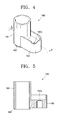
- FIG. 4 is a perspective view of the exhaust pipe protecting tip 160 according to an embodiment of the present invention
- FIG. 5 is a cross-sectional view of the exhaust pipe protecting tip 160 taken along line V-V of FIG. 4.
- the exhaust pipe protecting tip 160 includes a protecting portion 161, a mounting portion 162, and a guide 163.
- the protecting portion 161 is cylindrically-shaped with a hollow inner space.
- the exhaust pipe 150 is located inside the protecting portion 161 after assembling the plasma display module 100, and thus, the protecting portion 161 protects the exhaust pipe 150.
- the mounting portion 162 is formed on a side portion of the protecting portion 161, and fixes the protecting portion 161 to the ear portion 134. That is, a hole 162a is formed in the mounting portion 162, and the hole 162a is matched to the boss 134a formed on the ear portion 134, and then, the mounting portion 162 is fixed to the boss 134a using a bolt 162b.
- the guide 163 protrudes from an end portion of the protecting portion 161, and is inserted into the exhaust hole 134b formed on the ear portion 134 when the exhaust pipe protecting tip 160 is installed on the chassis 130.
- the protecting portion 161, the mounting portion 162, and the guide 163 are formed of a plastic material, and they are integrally formed with each other using an injection molding method. That is, the exhaust pipe protecting tip 160 including the protecting portion 161, the mounting portion 162, and the guide 163 is formed using the injection molding method, and thus, fabrication time and the number of processes can be reduced.
- the protecting portion 161, the mounting portion 162, and the guide 163 are formed of a plastic material, however, they are not limited thereto, and can be formed of a metal or other nonmetallic materials. Further, it is possible that these three elements are formed separately from each other and attached instead of being integrally formed.
- the exhaust pipe protecting tip 160 can be fixed onto the ear portion 134 simply and firmly.
- a bead 170 is formed on an upper left corner of the chassis 130 , e.g., by pushing in a part of the chassis 130, so as to reinforce the strength of that ear portion 134, and reinforcing members 134c are additionally installed on other corners of the chassis 130 for reinforcing the strength of the other ear portions 134.
- the bead 170 is formed on the upper left corner of the chassis 130, and thus, there is no need to install the reinforcing member 134c on the upper left corner of the chassis 130. Therefore, the exhaust pipe protecting tip 160 can be installed easily.
- a first end of the bead 170 formed on the upper left corner of the chassis 130 is located at that ear portion 134, and a second end of the bead 170 extends to the chassis base 131.
- the bead 170 is straight.
- the present invention is not limited to the above example, and if the bead 170 can reinforce the strength of that ear portion 134, the bead 170 can be positioned at any portion of the chassis 130 and can have various shapes such as a bent shape, a circular arc, or an oval shape.
- a width of the bead 170 can be determined appropriately by a designer according to a degree of strength to be reinforced.
- the bead 170 according to an aspect of the present embodiment is formed using a pressing process. However, it can be formed using other metal forming methods or casting methods.
- the bead 170 protrudes from the rear surface of the chassis base 130 to be embossed so that the plasma display panel 110 can be installed easily since the plasma display panel 110 is located on the front surface of the chassis 130.
- the bead 170 is not limited to the above example, and the bead 170 can protrude from the front surface of the chassis base to be engraved if the bead 170 does not interfere with the installation of the plasma display panel 110.
- a single bead 170 is formed on the upper left corner of the chassis 130, on which the exhaust pipe protecting tip 160 is mounted.
- a plurality of beads 170 may be formed in order to reinforce the strength of the ear portion 134.
- the bead 170 is only formed on the upper left corner of the chassis 130, on which the exhaust pipe protecting tip 160 is mounted.
- beads 170 can be formed on the other remaining corners of the chassis 130, thereby eliminating the need for the reinforcing members 134c.
- the exhaust pipe protecting tip 160 having the guide 163 formed of the plastic material is separately fabricated using an injection molding method, and after that, is mounted onto the ear portion 134 of the chassis 130. Therefore, there is no need to forcibly insert the exhaust pipe protecting tip 160, the number of processes can be reduced, and the time and costs for fabricating and installing the exhaust pipe protecting tip 160 can be reduced. In addition, the exhaust pipe protecting tip 160 can be located at an exact position, and thus, the exhaust pipe is not damaged during the assembling processes.
- the bead 170 can be formed on a side portion of the exhaust pipe protecting tip 160, and thus the ear portion 134 on which the exhaust pipe protecting tip 160 is mounted can be reinforced simply and efficiently without using an additional reinforcing member.
- the exhaust pipe protecting tip including the guide is separately fabricated and mounted on the ear portion of the chassis, and thus, the exhaust pipe can be protected and the exhaust pipe protecting tip can be installed efficiently.
- the exhaust pipe protecting tip when the exhaust pipe protecting tip is installed according to aspects of the present invention, a process of forcibly inserting the exhaust pipe protecting tip into the corresponding ear portion is not necessary or performed, and thus, the number of processes is reduced and the fabrication costs can be reduced. Therefore, the exhaust pipe protecting tip can be installed at an exact position, and thus, the exhaust pipe is not damaged during the assembling processes.
- an essential space required to perform the forcible insertion process is not required according to aspects of the present invention, and thus, the width of the ear portion can be controlled appropriately and the remaining space of the chassis can be more efficiently utilized.
- a process of forming an additional reinforcing member for reinforcing the ear portion of the chassis on which the exhaust pipe protecting tip is installed is not required, and the ear portion can be reinforced by forming the bead using a simple method such as a pressing method. Therefore, the number of processes for fabricating the ear portion can be reduced, and thus, time and costs taken to fabricate the chassis can be reduced.
Landscapes
- Physics & Mathematics (AREA)
- Engineering & Computer Science (AREA)
- Plasma & Fusion (AREA)
- Devices For Indicating Variable Information By Combining Individual Elements (AREA)
- Gas-Filled Discharge Tubes (AREA)
Abstract
Description
- Aspects of the present invention relate to an exhaust pipe protecting tip and a plasma display module including the exhaust pipe protecting tip, and more particularly, to an exhaust pipe protecting tip, which can protect the exhaust pipe and improves an ease of fabrication of the exhaust pipe protecting tip through separate fabrication of the exhaust pipe protecting tip having a guide and attaching the exhaust pipe protecting tip to an ear portion of a chassis, and a plasma display module including the exhaust pipe protecting tip.
- Plasma display panels (PDPs) that have begun to replace conventional cathode ray tubes (CRTs) are apparatuses for displaying images. In a plasma display panel, a discharge gas is sealed between two substrates having a plurality of electrodes, the discharge gas being supplied to generate ultraviolet rays, and phosphor layers formed in a predetermined pattern are excited by the ultraviolet rays to emit visible rays, and thus, an image is obtained.
- FIG. 1 is a perspective view of an ear portion of a
chassis 10, on which an exhaust pipe protecting tip is installed, used in a conventional plasma display module. - Referring to FIG. 1, the
chassis 10 supporting a plasma display panel and a circuit board is rectangular in shape, and includes achassis base 11, afirst bending portion 12, asecond bending portion 13, and anear portion 14. - The
ear portion 14 is formed at a corner of thechassis 10, andbosses 15 are formed on theear portion 14 for fixing thechassis 10 onto a case (not shown). - Since the
ear portion 14 extends from thechassis base 11 and there is no supporting unit for supporting theear portion 14, a reinforcingmaterial 20 is mounted on theear portion 14 for reinforcing theear portion 14. - In general, an exhaust
pipe protecting tip 16 for protecting an exhaust pipe formed on a rear surface of the plasma display panel is formed on theear portion 14, and the exhaustpipe protecting tip 16 is tube-shaped. - However, in the conventional structure illustrated in FIG. 1 for protecting the exhaust pipe, the exhaust
pipe protecting tip 16 is forcibly inserted into theear portion 14 of thechassis 10, but may be out of tolerance. First, a hole is formed in theear portion 14 and theear portion 14 is prepared for dying using a jig. Next, the exhaustpipe protecting tip 16 is placed into a hole of theear portion 14, and a force is applied to the exhaustpipe protecting tip 16. In addition to the need for these operations, when assembling the plasma display module, the exhaustpipe protecting tip 16 may collide with the exhaust pipe, and the exhaust pipe may be damaged. - In addition, in order to perform the insertion process for forming the structure of the exhaust
pipe protecting tip 16, the number of processes increases and fabrication costs rise. In addition, a predetermined space is required in order to perform the insertion process, and accordingly, the width of theear portion 14 should be enlarged. - Aspects of the present invention provide an exhaust pipe protecting tip, which can protect an exhaust pipe and improve an ease of fabrication of the exhaust pipe protecting tip through separate fabrication of the exhaust pipe protecting tip including a guide and attachment of the exhaust pipe protecting tip to an ear portion of a chassis, and a plasma display module including the exhaust pipe protecting tip.
- According to an aspect of the present invention, there is provided an exhaust pipe protecting tipfor protecting an exhaust pipe of a plasma display module having a chassis with an ear portion and an exhaust hole for the exhaust pipe, the exhaust pipe protecting tip including: a protecting portion being cylindrically-shaped and to protect the exhaust pipe; a mounting portion formed on a side surface of the protecting portion, to fix the protecting portion to the ear portion of the chassis; and a guide protruding from an end of the protecting portion, to be inserted into the exhaust hole of the chassis.
- The mounting portion may include a hole to receive the boss formed on the chassis, and the mounting portion is attached to the boss using a bolt.
- The protecting portion, the mounting portion, and the guide may be integrally formed with each other.
- The protecting portion, the mounting portion, and the guide may be formed of a plastic material.
- The protecting portion, the mounting portion, and the guide may be formed using an injection molding method.
- According to another aspect of the present invention, there is provided a plasma display module including: a plasma display panel displaying an image and including an exhaust pipe; a plurality of circuit boards driving the plasma display panel; a chassis supporting the plasma display panel and the circuit boards, and including an ear portion on the chassis, and an exhaust hole in which the exhaust pipe is inserted; and an exhaust pipe protecting tip including: a protecting portion being cylindrically-shaped and to protect the exhaust pipe, a mounting portion formed on a side surface of the protecting portion, to fix the protecting portion to the ear portion of the chassis, and a guide protruding from an end of the protecting portion, to be inserted into the exhaust hole of the chassis.
- The ear portion may include a boss and the mounting portion may include a hole, the boss may be matched to the hole of the mounting portion, and the mounting portion may be attached to the boss using a bolt.
- The protecting portion, the mounting portion, and the guide may be integrally formed with each other.
- The protecting portion, the mounting portion, and the guide may be formed of a plastic material.
- The protecting portion, the mounting portion, and the guide are formed using an injection molding method.
- The module may further include a bead extending from a base of the chassis to the ear portion to reinforce the ear portion.
- The bead may have a straight shape. At least a portion of the bead may be bent. In addition, a plurality of beads may be formed.
- Additional aspects and/or advantages of the invention will be set forth in part in the description which follows and, in part, will be obvious from the description, or may be learned by practice of the invention.
- These and/or other aspects and advantages of the invention will become apparent and more readily appreciated from the following description of the embodiments, taken in conjunction with the accompanying drawings of which:
- FIG. 1 is a perspective view of an ear portion on which an exhaust pipe protecting tip is installed among ear portions of a chassis used in a plasma display module according to the conventional art;
- FIG. 2 is a schematic exploded perspective view of a plasma display module according to an embodiment of the present invention;
- FIG. 3 is a perspective view of an ear portion at an upper left corner of a chassis of FIG. 2;
- FIG. 4 is a perspective view of a structure of an exhaust pipe protecting tip according to an embodiment of the present invention; and
- FIG. 5 is a cross-sectional view of the structure of the exhaust pipe protecting tip taken along line V-V of FIG. 4.
- Reference will now be made in detail to the present embodiments of the present invention, examples of which are illustrated in the accompanying drawings, wherein like reference numerals refer to the like elements throughout. The embodiments are described below in order to explain the present invention by referring to the figures.
- FIG. 2 is a schematic exploded perspective view of a
plasma display module 100 according to an embodiment of the present invention, and FIG. 3 is a perspective view of an ear portion formed at an upper left corner of a chassis of FIG. 2. - Referring to FIG. 2, the
plasma display module 100 according to an embodiment of the present invention includes aplasma display panel 110, a plurality ofcircuit boards 120 on which circuits for driving theplasma display panel 110 are disposed, and achassis 130 supporting theplasma display panel 110 and thecircuit boards 120. - The
plasma display panel 110 which displays images, includes afront substrate 111 and arear substrate 112 that are coupled to each other, and is electrically connected to thecircuit boards 120 throughsignal transmission members 140. In addition, anexhaust pipe 150 is located at a rear surface of the rear substrate 112 (see upper left region of the rear substrate 112) for exhausting an impurity gas in theplasma display panel 110 after sealing theplasma display panel 110. - The
chassis 130 includes achassis base 131,first bending portions 132 at opposite sides of thechassis 130,second bending portions 133 at other opposite sides of thechassis 130, andear portions 134 respectively extending from thechassis base 131 at the four corners of thechassis 130. Thechassis 130 is generally formed of a metal such as aluminum using a casting method or a pressing method. - The
plasma display panel 110 is fixed onto a front surface of thechassis base 131 to be supported by thechassis base 131, and thecircuit boards 120 are supported by a rear surface of thechassis base 131. Besides the function of supporting theplasma display panel 110, thechassis base 131 receives heat generated by theplasma display panel 110 during operation and dissipates the heat to cool down theplasma display panel 110. - The
first bending portions 132 reinforce the rigidity of thechassis 130, and protect thecircuit boards 120 mounted on thechassis base 131 when assembling or moving theplasma display panel 110. - The
second bending portions 133 also reinforce the rigidity of thechassis 130, and protect thecircuit boards 120 mounted on thechassis base 131 when assembling or moving theplasma display panel 110. In addition, thesecond bending portions 133 support integrated circuit (IC)chips 141 formed on thesignal transmission members 140 that transmit address signals, and dissipate heat from theIC chips 141. - Each of the
ear portions 134 includes at least oneboss 134a, and thebosses 134a are used to mount thechassis 130 in the case (not shown). Theboss 134a on one of the ear portions 134 (see upper left portion of thechassis 130 in FIG. 2) is used to fix the exhaustpipe protecting tip 160. - In particular, referring to FIG. 3, the
ear portion 134 formed on the upper left corner of thechassis 130 includes anexhaust hole 134b in which theexhaust pipe 150 is inserted. - FIG. 4 is a perspective view of the exhaust
pipe protecting tip 160 according to an embodiment of the present invention, and FIG. 5 is a cross-sectional view of the exhaustpipe protecting tip 160 taken along line V-V of FIG. 4. - Referring to FIGS. 3, 4, and 5, the exhaust
pipe protecting tip 160 includes a protectingportion 161, amounting portion 162, and aguide 163. - The
protecting portion 161 is cylindrically-shaped with a hollow inner space. Theexhaust pipe 150 is located inside the protectingportion 161 after assembling theplasma display module 100, and thus, the protectingportion 161 protects theexhaust pipe 150. - The
mounting portion 162 is formed on a side portion of the protectingportion 161, and fixes the protectingportion 161 to theear portion 134. That is, ahole 162a is formed in themounting portion 162, and thehole 162a is matched to theboss 134a formed on theear portion 134, and then, themounting portion 162 is fixed to theboss 134a using abolt 162b. - The
guide 163 protrudes from an end portion of the protectingportion 161, and is inserted into theexhaust hole 134b formed on theear portion 134 when the exhaustpipe protecting tip 160 is installed on thechassis 130. - The protecting
portion 161, the mountingportion 162, and theguide 163 are formed of a plastic material, and they are integrally formed with each other using an injection molding method. That is, the exhaustpipe protecting tip 160 including the protectingportion 161, the mountingportion 162, and theguide 163 is formed using the injection molding method, and thus, fabrication time and the number of processes can be reduced. - According to aspects of the present embodiment, the protecting
portion 161, the mountingportion 162, and theguide 163 are formed of a plastic material, however, they are not limited thereto, and can be formed of a metal or other nonmetallic materials. Further, it is possible that these three elements are formed separately from each other and attached instead of being integrally formed. - When an operator assembles the
plasma display module 100, he/she inserts theguide 163 into theexhaust hole 134b, and matches thehole 162a formed on the mountingportion 162 with theboss 134a, and then fixes them using thebolt 162. Therefore, the exhaustpipe protecting tip 160 can be fixed onto theear portion 134 simply and firmly. - Meanwhile, referring to FIGS. 2 and 3, a
bead 170 is formed on an upper left corner of thechassis 130 , e.g., by pushing in a part of thechassis 130, so as to reinforce the strength of thatear portion 134, and reinforcingmembers 134c are additionally installed on other corners of thechassis 130 for reinforcing the strength of theother ear portions 134. - That is, according to an aspect of the present embodiment, the
bead 170 is formed on the upper left corner of thechassis 130, and thus, there is no need to install the reinforcingmember 134c on the upper left corner of thechassis 130. Therefore, the exhaustpipe protecting tip 160 can be installed easily. - A first end of the
bead 170 formed on the upper left corner of thechassis 130 is located at thatear portion 134, and a second end of thebead 170 extends to thechassis base 131. In addition, according to an aspect of the present embodiment, thebead 170 is straight. However, the present invention is not limited to the above example, and if thebead 170 can reinforce the strength of thatear portion 134, thebead 170 can be positioned at any portion of thechassis 130 and can have various shapes such as a bent shape, a circular arc, or an oval shape. - A width of the
bead 170 can be determined appropriately by a designer according to a degree of strength to be reinforced. - In addition, the
bead 170 according to an aspect of the present embodiment is formed using a pressing process. However, it can be formed using other metal forming methods or casting methods. - The
bead 170 protrudes from the rear surface of thechassis base 130 to be embossed so that theplasma display panel 110 can be installed easily since theplasma display panel 110 is located on the front surface of thechassis 130. However, thebead 170 is not limited to the above example, and thebead 170 can protrude from the front surface of the chassis base to be engraved if thebead 170 does not interfere with the installation of theplasma display panel 110. - In addition, a
single bead 170 is formed on the upper left corner of thechassis 130, on which the exhaustpipe protecting tip 160 is mounted. However, a plurality ofbeads 170 may be formed in order to reinforce the strength of theear portion 134. - Also, according to an aspect of the present embodiment, the
bead 170 is only formed on the upper left corner of thechassis 130, on which the exhaustpipe protecting tip 160 is mounted. However,beads 170 can be formed on the other remaining corners of thechassis 130, thereby eliminating the need for the reinforcingmembers 134c. - As described above, according to aspects of the present embodiment, the exhaust
pipe protecting tip 160 having theguide 163 formed of the plastic material is separately fabricated using an injection molding method, and after that, is mounted onto theear portion 134 of thechassis 130. Therefore, there is no need to forcibly insert the exhaustpipe protecting tip 160, the number of processes can be reduced, and the time and costs for fabricating and installing the exhaustpipe protecting tip 160 can be reduced. In addition, the exhaustpipe protecting tip 160 can be located at an exact position, and thus, the exhaust pipe is not damaged during the assembling processes. - Also, the
bead 170 can be formed on a side portion of the exhaustpipe protecting tip 160, and thus theear portion 134 on which the exhaustpipe protecting tip 160 is mounted can be reinforced simply and efficiently without using an additional reinforcing member. - According to aspects of the present invention, the exhaust pipe protecting tip including the guide is separately fabricated and mounted on the ear portion of the chassis, and thus, the exhaust pipe can be protected and the exhaust pipe protecting tip can be installed efficiently.
- That is, when the exhaust pipe protecting tip is installed according to aspects of the present invention, a process of forcibly inserting the exhaust pipe protecting tip into the corresponding ear portion is not necessary or performed, and thus, the number of processes is reduced and the fabrication costs can be reduced. Therefore, the exhaust pipe protecting tip can be installed at an exact position, and thus, the exhaust pipe is not damaged during the assembling processes.
- In addition, an essential space required to perform the forcible insertion process is not required according to aspects of the present invention, and thus, the width of the ear portion can be controlled appropriately and the remaining space of the chassis can be more efficiently utilized.
- According to aspects of the present invention, a process of forming an additional reinforcing member for reinforcing the ear portion of the chassis on which the exhaust pipe protecting tip is installed is not required, and the ear portion can be reinforced by forming the bead using a simple method such as a pressing method. Therefore, the number of processes for fabricating the ear portion can be reduced, and thus, time and costs taken to fabricate the chassis can be reduced.
Claims (17)
- An exhaust pipe protecting tip for protecting an exhaust pipe of a plasma display module having a chassis with an ear portion and an exhaust hole for the exhaust pipe, the exhaust pipe protecting tip comprising:a protecting portion being cylindrically-shaped and to protect the exhaust pipe;a mounting portion formed on a side surface of the protecting portion, to fix the protecting portion to the ear portion of the chassis; anda guide protruding from an end of the protecting portion, to be inserted into the exhaust hole of the chassis.
- The exhaust pipe protecting tip of claim 1, wherein the ear portion has a boss, wherein:the mounting portion includes a hole to receive the boss formed on the chassis, and the mounting portion is attached to the boss using a bolt.
- The exhaust pipe protecting tip of claim 1, wherein the protecting portion, the mounting portion, and the guide are integrally formed with each other.
- The exhaust pipe protecting tip of claim 1, wherein the protecting portion, the mounting portion, and the guide are formed of a plastic material.
- The exhaust pipe protecting tip of claim 1, wherein the protecting portion, the mounting portion, and the guide are formed using an injection molding method.
- The exhaust pipe protecting tip of claim 1, wherein the protecting portion, the mounting portion, and the guide are formed of a metallic material.
- A plasma display module comprising:a plasma display panel displaying an image and including an exhaust pipe;a plurality of circuit boards driving the plasma display panel;a chassis supporting the plasma display panel and the circuit boards, and including an ear portion on the chassis, and an exhaust hole in which the exhaust pipe is inserted; andan exhaust pipe protecting tip comprising:a protecting portion being cylindrically-shaped and to protect the exhaust pipe,a mounting portion formed on a side surface of the protecting portion, to fix the protecting portion to the ear portion of the chassis, anda guide protruding from an end of the protecting portion, to be inserted into the exhaust hole of the chassis.
- The plasma display module of claim 7, wherein the ear portion includes a boss and the mounting portion includes a hole, the boss is matched to the hole of the mounting portion, and the mounting portion is attached to the boss using a bolt.
- The plasma display module of claim 7, wherein the protecting portion, the mounting portion, and the guide are integrally formed with each other.
- The plasma display module of claim 7, wherein the protecting portion, the mounting portion, and the guide are formed of a plastic material.
- The plasma display module of claim 7, wherein the protecting portion, the mounting portion, and the guide are formed using an injection molding method.
- The plasma display module of claim 7, further comprising:a bead extending from a base of the chassis to the ear portion to reinforce the ear portion.
- The plasma display module of claim 12, wherein the bead has a straight shape.
- The plasma display module of claim 12, wherein at least a portion of the bead is bent.
- The plasma display module of claim 12, wherein a plurality of beads extend from the base to the ear portion to reinforce the ear portion.
- The plasma display module of claim 7, wherein the protecting portion, the mounting portion, and the guide are formed of a metallic material.
- The plasma display module of claim 12, wherein the bead is at or near a side of the exhaust pipe protecting tip and on a same surface of the chassis as the exhaust pipe protecting tip.
Applications Claiming Priority (1)
| Application Number | Priority Date | Filing Date | Title |
|---|---|---|---|
| KR1020050010966A KR100846584B1 (en) | 2005-02-05 | 2005-02-05 | Exhaust Pipe Protection Tip Structure and Plasma Display Module |
Publications (3)
| Publication Number | Publication Date |
|---|---|
| EP1688983A2 true EP1688983A2 (en) | 2006-08-09 |
| EP1688983A3 EP1688983A3 (en) | 2006-08-16 |
| EP1688983B1 EP1688983B1 (en) | 2007-08-08 |
Family
ID=36577580
Family Applications (1)
| Application Number | Title | Priority Date | Filing Date |
|---|---|---|---|
| EP06100954A Expired - Lifetime EP1688983B1 (en) | 2005-02-05 | 2006-01-27 | An exhaust pipe protecting tip and plasma display module including the same |
Country Status (6)
| Country | Link |
|---|---|
| US (1) | US7433180B2 (en) |
| EP (1) | EP1688983B1 (en) |
| JP (1) | JP2006215565A (en) |
| KR (1) | KR100846584B1 (en) |
| CN (1) | CN1828806B (en) |
| DE (1) | DE602006000059T2 (en) |
Families Citing this family (7)
| Publication number | Priority date | Publication date | Assignee | Title |
|---|---|---|---|---|
| KR100813843B1 (en) | 2006-09-13 | 2008-03-17 | 삼성에스디아이 주식회사 | Plasma display module |
| CN101719450B (en) * | 2008-12-24 | 2011-08-24 | 四川虹欧显示器件有限公司 | Exhaust pipe protective cap and plasma display module with protective cap |
| CN101728159B (en) * | 2008-12-24 | 2011-09-07 | 四川虹欧显示器件有限公司 | Plasma display module and vent pipe protection cap thereof |
| JP2015108643A (en) * | 2012-03-13 | 2015-06-11 | パナソニック株式会社 | Thin display device |
| WO2013136639A1 (en) * | 2012-03-13 | 2013-09-19 | パナソニック株式会社 | Thin display device |
| JP6236892B2 (en) * | 2013-06-07 | 2017-11-29 | 株式会社デンソー | Display device |
| CN208295944U (en) * | 2018-05-14 | 2018-12-28 | 芜湖美的厨卫电器制造有限公司 | Smoke evacuation component and gas heater |
Family Cites Families (10)
| Publication number | Priority date | Publication date | Assignee | Title |
|---|---|---|---|---|
| KR100307620B1 (en) | 1994-11-30 | 2001-12-01 | 윤종용 | Modules for buses to use backplane buses in a time-division manner |
| KR100283861B1 (en) | 1998-06-13 | 2001-03-02 | 배길성 | Robot cleaner |
| JP3628188B2 (en) * | 1998-06-30 | 2005-03-09 | パイオニア株式会社 | Plasma display panel |
| KR20000001763U (en) * | 1998-06-30 | 2000-01-25 | 전주범 | PDP Glass Substrate Exhaust Protector |
| CN1153243C (en) * | 1999-03-01 | 2004-06-09 | 中外炉工业株式会社 | Exhaust sealing method for plasma display panel |
| JP3443775B2 (en) * | 2001-01-18 | 2003-09-08 | サンエス護謨工業株式会社 | Joint |
| FR2830678A1 (en) * | 2001-10-10 | 2003-04-11 | Thomson Licensing Sa | TUBE FOR PUMPING A SPACE BETWEEN TWO SLABS, IN PARTICULAR A PLASMA PANEL |
| WO2004064103A1 (en) * | 2003-01-14 | 2004-07-29 | Asahi Techno Glass Corporation | Glass tube, method of manufacturing the glass tube, and method of adhering the glass tube |
| KR100563048B1 (en) * | 2003-09-25 | 2006-03-24 | 삼성에스디아이 주식회사 | Plasma display assembly |
| JP2008019961A (en) * | 2006-07-12 | 2008-01-31 | Ntn Corp | Fixed constant velocity universal joint |
-
2005
- 2005-02-05 KR KR1020050010966A patent/KR100846584B1/en not_active Expired - Fee Related
-
2006
- 2006-01-27 DE DE602006000059T patent/DE602006000059T2/en not_active Expired - Lifetime
- 2006-01-27 EP EP06100954A patent/EP1688983B1/en not_active Expired - Lifetime
- 2006-01-31 US US11/342,878 patent/US7433180B2/en not_active Expired - Fee Related
- 2006-02-02 JP JP2006025245A patent/JP2006215565A/en active Pending
- 2006-02-05 CN CN2006100040235A patent/CN1828806B/en not_active Expired - Fee Related
Also Published As
| Publication number | Publication date |
|---|---|
| KR20060090435A (en) | 2006-08-11 |
| JP2006215565A (en) | 2006-08-17 |
| CN1828806A (en) | 2006-09-06 |
| DE602006000059T2 (en) | 2008-05-08 |
| EP1688983A3 (en) | 2006-08-16 |
| EP1688983B1 (en) | 2007-08-08 |
| DE602006000059D1 (en) | 2007-09-20 |
| CN1828806B (en) | 2010-06-23 |
| US7433180B2 (en) | 2008-10-07 |
| US20060181210A1 (en) | 2006-08-17 |
| KR100846584B1 (en) | 2008-07-16 |
Similar Documents
| Publication | Publication Date | Title |
|---|---|---|
| CN100349500C (en) | Display apparatus with stress distribution device | |
| US20060089023A1 (en) | Frame bracket for printed board asembly and plasma display device having the same | |
| KR100649186B1 (en) | Plasma display device | |
| KR100670252B1 (en) | Chassis base assembly, method for manufacturing same, and plasma display assembly using the same | |
| CN1873835B (en) | Plastic chassis and plasma display device including the same | |
| EP2063698A1 (en) | Plasma display device | |
| KR20060114533A (en) | Mounting structure of flat panel display module and flat panel display module having same | |
| US7433180B2 (en) | Exhaust pipe protecting tip and plasma display module including the same | |
| JP2006338006A (en) | Plasma display panel | |
| KR100553211B1 (en) | Plasma display device | |
| US7864545B2 (en) | Chassis base assembly and plasma display panel (PDP) assembly including the chassis base assembly | |
| EP1901597B1 (en) | Plasma display module | |
| JP2007309962A (en) | Plasma display device | |
| US20070008243A1 (en) | Plasma display panel (PDP) | |
| US20060187144A1 (en) | Mounting structure of cover plate and plasma display module including the same | |
| KR100484108B1 (en) | Cover for circuit board of plasma display panel | |
| US20080252557A1 (en) | Plasma display and its method of manufacture | |
| KR100884800B1 (en) | Flat panel display module | |
| KR20060082175A (en) | Chassis Ear Structure and Plasma Display Module | |
| KR100731447B1 (en) | Chassis base and plasma display device having same | |
| KR100683765B1 (en) | Boss combined reinforcement member in display panel module | |
| JP2008116523A (en) | Display equipment and display panel | |
| KR100659098B1 (en) | Plasma display module | |
| KR100570603B1 (en) | Plasma display device | |
| KR20060119590A (en) | Flat panel display |
Legal Events
| Date | Code | Title | Description |
|---|---|---|---|
| PUAI | Public reference made under article 153(3) epc to a published international application that has entered the european phase |
Free format text: ORIGINAL CODE: 0009012 |
|
| PUAL | Search report despatched |
Free format text: ORIGINAL CODE: 0009013 |
|
| 17P | Request for examination filed |
Effective date: 20060127 |
|
| AK | Designated contracting states |
Kind code of ref document: A2 Designated state(s): AT BE BG CH CY CZ DE DK EE ES FI FR GB GR HU IE IS IT LI LT LU LV MC NL PL PT RO SE SI SK TR |
|
| AX | Request for extension of the european patent |
Extension state: AL BA HR MK YU |
|
| AK | Designated contracting states |
Kind code of ref document: A3 Designated state(s): AT BE BG CH CY CZ DE DK EE ES FI FR GB GR HU IE IS IT LI LT LU LV MC NL PL PT RO SE SI SK TR |
|
| AX | Request for extension of the european patent |
Extension state: AL BA HR MK YU |
|
| 17Q | First examination report despatched |
Effective date: 20060802 |
|
| RIN1 | Information on inventor provided before grant (corrected) |
Inventor name: AHN, JOONG-HA Inventor name: KIM, DONG-HWAN |
|
| GRAP | Despatch of communication of intention to grant a patent |
Free format text: ORIGINAL CODE: EPIDOSNIGR1 |
|
| AKX | Designation fees paid |
Designated state(s): DE FR GB NL |
|
| GRAS | Grant fee paid |
Free format text: ORIGINAL CODE: EPIDOSNIGR3 |
|
| GRAA | (expected) grant |
Free format text: ORIGINAL CODE: 0009210 |
|
| RIN1 | Information on inventor provided before grant (corrected) |
Inventor name: KIM, DONG-HWAN Inventor name: AHN, JOONG-HA |
|
| AK | Designated contracting states |
Kind code of ref document: B1 Designated state(s): DE FR GB NL |
|
| REG | Reference to a national code |
Ref country code: GB Ref legal event code: FG4D |
|
| REF | Corresponds to: |
Ref document number: 602006000059 Country of ref document: DE Date of ref document: 20070920 Kind code of ref document: P |
|
| ET | Fr: translation filed | ||
| PLBE | No opposition filed within time limit |
Free format text: ORIGINAL CODE: 0009261 |
|
| STAA | Information on the status of an ep patent application or granted ep patent |
Free format text: STATUS: NO OPPOSITION FILED WITHIN TIME LIMIT |
|
| 26N | No opposition filed |
Effective date: 20080509 |
|
| PGFP | Annual fee paid to national office [announced via postgrant information from national office to epo] |
Ref country code: FR Payment date: 20130215 Year of fee payment: 8 Ref country code: DE Payment date: 20130117 Year of fee payment: 8 Ref country code: GB Payment date: 20130111 Year of fee payment: 8 |
|
| PGFP | Annual fee paid to national office [announced via postgrant information from national office to epo] |
Ref country code: NL Payment date: 20130116 Year of fee payment: 8 |
|
| REG | Reference to a national code |
Ref country code: DE Ref legal event code: R119 Ref document number: 602006000059 Country of ref document: DE |
|
| REG | Reference to a national code |
Ref country code: NL Ref legal event code: V1 Effective date: 20140801 |
|
| GBPC | Gb: european patent ceased through non-payment of renewal fee |
Effective date: 20140127 |
|
| REG | Reference to a national code |
Ref country code: DE Ref legal event code: R119 Ref document number: 602006000059 Country of ref document: DE Effective date: 20140801 |
|
| PG25 | Lapsed in a contracting state [announced via postgrant information from national office to epo] |
Ref country code: NL Free format text: LAPSE BECAUSE OF NON-PAYMENT OF DUE FEES Effective date: 20140801 Ref country code: DE Free format text: LAPSE BECAUSE OF NON-PAYMENT OF DUE FEES Effective date: 20140801 |
|
| REG | Reference to a national code |
Ref country code: FR Ref legal event code: ST Effective date: 20140930 |
|
| PG25 | Lapsed in a contracting state [announced via postgrant information from national office to epo] |
Ref country code: GB Free format text: LAPSE BECAUSE OF NON-PAYMENT OF DUE FEES Effective date: 20140127 Ref country code: FR Free format text: LAPSE BECAUSE OF NON-PAYMENT OF DUE FEES Effective date: 20140131 |