EP1688977A2 - Surface pressing button and electronic device including the same - Google Patents
Surface pressing button and electronic device including the same Download PDFInfo
- Publication number
- EP1688977A2 EP1688977A2 EP06002551A EP06002551A EP1688977A2 EP 1688977 A2 EP1688977 A2 EP 1688977A2 EP 06002551 A EP06002551 A EP 06002551A EP 06002551 A EP06002551 A EP 06002551A EP 1688977 A2 EP1688977 A2 EP 1688977A2
- Authority
- EP
- European Patent Office
- Prior art keywords
- surface pressing
- pressing part
- button
- front panel
- switch
- Prior art date
- Legal status (The legal status is an assumption and is not a legal conclusion. Google has not performed a legal analysis and makes no representation as to the accuracy of the status listed.)
- Granted
Links
- 238000003825 pressing Methods 0.000 title claims abstract description 196
- 230000003014 reinforcing effect Effects 0.000 claims description 6
- 239000000758 substrate Substances 0.000 description 6
- 230000000149 penetrating effect Effects 0.000 description 4
- 238000004519 manufacturing process Methods 0.000 description 2
- 239000000463 material Substances 0.000 description 1
- 238000000034 method Methods 0.000 description 1
- 238000012986 modification Methods 0.000 description 1
- 230000004048 modification Effects 0.000 description 1
- 238000000465 moulding Methods 0.000 description 1
- 239000011347 resin Substances 0.000 description 1
- 229920005989 resin Polymers 0.000 description 1
Images



Classifications
-
- H—ELECTRICITY
- H01—ELECTRIC ELEMENTS
- H01H—ELECTRIC SWITCHES; RELAYS; SELECTORS; EMERGENCY PROTECTIVE DEVICES
- H01H21/00—Switches operated by an operating part in the form of a pivotable member acted upon directly by a solid body, e.g. by a hand
- H01H21/02—Details
- H01H21/18—Movable parts; Contacts mounted thereon
- H01H21/22—Operating parts, e.g. handle
- H01H21/24—Operating parts, e.g. handle biased to return to normal position upon removal of operating force
-
- H—ELECTRICITY
- H01—ELECTRIC ELEMENTS
- H01H—ELECTRIC SWITCHES; RELAYS; SELECTORS; EMERGENCY PROTECTIVE DEVICES
- H01H13/00—Switches having rectilinearly-movable operating part or parts adapted for pushing or pulling in one direction only, e.g. push-button switch
- H01H13/02—Details
- H01H13/12—Movable parts; Contacts mounted thereon
- H01H13/14—Operating parts, e.g. push-button
-
- H—ELECTRICITY
- H01—ELECTRIC ELEMENTS
- H01H—ELECTRIC SWITCHES; RELAYS; SELECTORS; EMERGENCY PROTECTIVE DEVICES
- H01H13/00—Switches having rectilinearly-movable operating part or parts adapted for pushing or pulling in one direction only, e.g. push-button switch
- H01H13/70—Switches having rectilinearly-movable operating part or parts adapted for pushing or pulling in one direction only, e.g. push-button switch having a plurality of operating members associated with different sets of contacts, e.g. keyboard
- H01H13/702—Switches having rectilinearly-movable operating part or parts adapted for pushing or pulling in one direction only, e.g. push-button switch having a plurality of operating members associated with different sets of contacts, e.g. keyboard with contacts carried by or formed from layers in a multilayer structure, e.g. membrane switches
- H01H13/705—Switches having rectilinearly-movable operating part or parts adapted for pushing or pulling in one direction only, e.g. push-button switch having a plurality of operating members associated with different sets of contacts, e.g. keyboard with contacts carried by or formed from layers in a multilayer structure, e.g. membrane switches characterised by construction, mounting or arrangement of operating parts, e.g. push-buttons or keys
- H01H13/7057—Switches having rectilinearly-movable operating part or parts adapted for pushing or pulling in one direction only, e.g. push-button switch having a plurality of operating members associated with different sets of contacts, e.g. keyboard with contacts carried by or formed from layers in a multilayer structure, e.g. membrane switches characterised by construction, mounting or arrangement of operating parts, e.g. push-buttons or keys characterised by the arrangement of operating parts in relation to each other, e.g. pre-assembled groups of keys
-
- H—ELECTRICITY
- H01—ELECTRIC ELEMENTS
- H01H—ELECTRIC SWITCHES; RELAYS; SELECTORS; EMERGENCY PROTECTIVE DEVICES
- H01H3/00—Mechanisms for operating contacts
- H01H3/32—Driving mechanisms, i.e. for transmitting driving force to the contacts
- H01H3/46—Driving mechanisms, i.e. for transmitting driving force to the contacts using rod or lever linkage, e.g. toggle
- H01H2003/466—Driving mechanisms, i.e. for transmitting driving force to the contacts using rod or lever linkage, e.g. toggle using a living hinge to connect the levers
-
- H—ELECTRICITY
- H01—ELECTRIC ELEMENTS
- H01H—ELECTRIC SWITCHES; RELAYS; SELECTORS; EMERGENCY PROTECTIVE DEVICES
- H01H2221/00—Actuators
- H01H2221/008—Actuators other then push button
- H01H2221/016—Lever; Rocker
-
- H—ELECTRICITY
- H01—ELECTRIC ELEMENTS
- H01H—ELECTRIC SWITCHES; RELAYS; SELECTORS; EMERGENCY PROTECTIVE DEVICES
- H01H2221/00—Actuators
- H01H2221/024—Transmission element
-
- H—ELECTRICITY
- H01—ELECTRIC ELEMENTS
- H01H—ELECTRIC SWITCHES; RELAYS; SELECTORS; EMERGENCY PROTECTIVE DEVICES
- H01H2221/00—Actuators
- H01H2221/024—Transmission element
- H01H2221/03—Stoppers for on or off position
Definitions
- the present invention relates to a surface pressing button, and an electronic device including the surface pressing button, such as an audio device or a video device.
- An electronic device such as an audio device or a video device includes many surface pressing buttons to perform operations of the electronic device, on a front surface in many cases.
- the electronic device is a DVD (Digital Versatile Disc) player, it includes surface pressing buttons capable of performing operations such as power ON/OFF, playback, stop, and disc ejection, so that the operation related to the surface pressing button can be performed by pressing the surface pressing button.
- DVD Digital Versatile Disc
- FIG. 6 is a front view showing a DVD player which is an example of a conventional electronic device.
- a DVD player PM shown in Fig. 6 includes a slot Ih for a DVD medium, a power supply button 91p, a stop button 91a, a playback (pause) button 91b, a medium ejection button 91c to eject the DVD medium, and a front panel 92 on which the aforementioned buttons are provided.
- Fig. 7A is a sectional view showing a push button of the electronic device shown in Fig. 6 and Fig. 7B is a sectional view showing a mounting part of the electronic device shown in Fig. 6.
- the surface pressing button 91 is arranged so that a surface pressing part 911 may penetrate a through hole 921 formed in the front panel 92.
- Each of the four surface pressing buttons 91 includes the surface pressing part 911, a switch pressing part 912 integrally formed with the surface pressing part 911, and a supporting part 913 to support the surface pressing part 911 and the switch pressing part 912.
- the supporting part 913 includes a boss hole 914 to which a boss 922 of the front panel 92 which will be described later is inserted, and a hinge 915 which is connected to the surface pressing part 911 and supported so as to be cantilevered. As shown in Figs. 7A and 7B, the supporting part 913 supports the four surface pressing buttons 91 arranged in line through the hinges 915. An inclination preventing part 916 integrally formed with the supporting part 913 to prevent the surface pressing button 91 from inclining is formed between both ends and the adjacent surface pressing buttons 91.
- the boss hole 914 is also formed at the distal end of the inclination preventing part 916.
- boss 922 penetrates the boss hole 914 formed in the supporting part 913.
- An end of the boss 922 penetrating the boss hole 914 is heated to be fused and welded together to be fixed to the boss hole 914.
- a substrate 93 is provided on the side of the switch pressing part 912 of the surface pressing button 91, and a switch 94 is also provided on the side of the switch pressing part 912.
- the switch 94 is mounted on the substrate 93 and a small space is formed between the switch 94 and the switch pressing part 912.
- the hinge 915 of the supporting part 913 bends, and an end of the switch pressing part 912 is moved downward.
- the switch 94 is arranged in the moving direction of the end of the switch pressing part 912. Thus, when the switch pressing part 912 is moved downward, the switch 94 is pressed by the switch pressing part 912.
- the switch 94 When the surface pressing button 91 is pressed by strong force, the switch 94 receives a large load from the switch pressing part 912 and it could be damaged.
- the front panel 92 includes a hook 923 to prevent an end opposite to the hinge 913 of the surface pressing part 911 from being moved too much.
- the hook 923 is formed adjacent to the through hole 921 as shown in Fig. 7A.
- the hook 923 is integrally formed with the front panel 92.
- Japanese Unexamined Utility Model Publication No. 06-9023 (1994) discloses that a stopper rib is formed on a switch knob and, when the switch knob is pressed, the stopper rib abuts on a substrate holder to restrict an operation of the switch knob.
- Japanese Unexamined Patent Publication No. 2004-39324 discloses that a stopper is provided on each side of a pressing part and, when a button is pressed, the stopper comes into contact with a substrate and prevents the button from being pressed more than needs.
- the surface pressing button 91 includes the supporting part 913 and the boss hole 914 formed at the distal end of the inclination preventing part 916 which extends from the supporting part 913.
- the boss 922 is inserted into the each boss hole 914.
- the hook 923 which engages with the surface pressing part 911 to restrict the movement of the surface pressing part 911 is mounted on a position close to the through hole 921 in the front panel 92, when the surface pressing button 91 is mounted, the surface pressing part 911 comes into contact with the hook 923 also, so that it is difficult to mount the surface pressing button 91 on the front panel 92.
- the hook 923 is formed of a material having a certain degree of flexibility, when the surface pressing button 91 is mounted on the front panel 92, the hook 923 is bent and the surface pressing part 911 can easily engage with the through hole 921. However, since the hook 923 is flexible, it cannot support a force applied from the surface pressing part 911 sufficiently in some cases.
- the hook 923 and the front panel 92 are manufactured separately and after the surface pressing button 91 is mounted on the front panel 92, the hook 923 is mounted, in this case, it is troublesome to mount the hook 923 and the hook 923 cannot support the force applied from the surface pressing button 911 in some cases.
- the surface pressing button 91 could be unstably fixed because the lengths of the boss 922 and the boss hole 914 are shortened.
- the present invention has been made in order to solve the aforementioned problems and it is an object of the present invention to provide a surface pressing button which can be surely and easily mounted on a back surface of a front panel and prevent a switch from receiving a large load, and an electronic device including the surface pressing button.
- the present invention provides an electronic device including a front panel in which a through hole is formed, and a surface pressing button which is mounted on a back surface of the front panel and presses a switch.
- the surface pressing button includes a surface pressing part a portion of which is exposed from the through hole of the front panel, a switch pressing part which is integrally formed with the surface pressing part, a supporting part which supports the surface pressing part, and a hinge which connects the surface pressing part to the supporting part.
- the surface pressing part includes a projection which projects from an end on a side opposite to an end connected to the hinge.
- the supporting part includes a supporting frame which is in contact with the front panel and supports the surface pressing part through the hinge, an auxiliary supporting frame which is in contact with the front panel and is formed opposed to the supporting frame across the surface pressing part, a boss hole which is formed in each of the supporting frame and the auxiliary supporting frame, and is fitted and welded to a boss formed on the back surface of the front panel, and a reinforcing part which connects the supporting frame to the auxiliary supporting frame.
- the auxiliary supporting frame includes a stopper hole in which a portion on the side of the front panel is open, and a portion of the projection is provided, and a stopper which restricts movement of the projection, at the opposite end of the opening of the stopper hole.
- the surface pressing button can be smoothly mounted on the front panel.
- the surface pressing part of the surface pressing button can be promptly and accurately arranged in the through hole of the front panel.
- a plurality of surface pressing parts may be provided, and the supporting part may support the plurality of surface pressing parts arranged in line.
- the switch pressing part may press a switch at the opposite end of the surface pressing part, and the switch pressing part may be turned around the hinge to press the switch.
- the present invention also provides a surface pressing button mounted on a back surface of a front panel in which a through hole is formed.
- the surface pressing button includes a surface pressing part in which a portion thereof is exposed from the through hole of the front panel, a switch pressing part which is integrally formed with the surface pressing part, a supporting part which supports the surface pressing part, and a hinge which connects the surface pressing part to the supporting part.
- the surface pressing part includes a projection which projects from an end on a side opposite to an end connected to the hinge.
- the supporting part includes a supporting frame which is in contact with the front panel and supports the surface pressing part through the hinge, an auxiliary supporting frame which is in contact with the front panel and is formed opposed to the supporting frame across the surface pressing part, a boss hole which is formed in each of the supporting frame and the auxiliary supporting frame, and is fitted and welded to a boss formed on the back surface of the front panel, and a reinforcing part which connects the supporting frame to the auxiliary supporting frame.
- the auxiliary supporting frame includes a stopper hole in which a portion on the side of the front panel is open, and a portion of the projection is provided, and a stopper which restricts movement of the projection, at the opposite end of the opening of the stopper hole.
- the surface pressing button can be smoothly mounted on the front panel.
- the surface pressing part of the surface pressing button can be promptly and accurately arranged in the through hole of the front panel.
- a plurality of surface pressing parts may be provided, and the supporting part may support the plurality of surface pressing parts arranged in line.
- the switch pressing part may press a switch at the opposite end of the surface pressing part, and the switch pressing part may be turned around the hinge to press the switch.
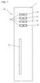
- Fig. 1 is a front view showing an example of an electronic device according to the present invention.
- An electronic device shown in Fig. 1 is a DVD player; however, the present invention is not limited thereto.
- the DVD player PL shown in Fig. 1 includes a slot Ih for a DVD medium, a power supply button 1 (1p), a stop button 1 (1a), a playback (pause) button 1 (1b), a medium ejection button 1 (1c) to eject the DVD medium, and a front panel 2.
- Each of the power supply button 1p, the stop button 1a, the playback button 1b and the medium ejection button 1c is pressed to perform an operation related to each button.
- Through holes 21 are formed in the front panel 2 and the respective buttons 1p, 1a, 1b and 1c penetrate the through holes 21.
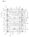
- Fig. 2 is a front view showing the surface pressing buttons according to the present invention
- Fig. 3 is a side view showing the surface pressing buttons shown in Fig. 2.
- the surface pressing buttons 1 include the power supply button 1p, the stop button 1a, the playback button 1b and the medium ejection button 1c.
- Each button has the same constitution and includes a surface pressing part 11 penetrating the through hole 21 of the front panel 2, and a switch pressing part 12 integrally connected to the surface pressing part 11.
- a manufacturing method of the surface pressing button 1 is an integral molding of resin in this example; however, the present invention is not limited thereto.
- the surface pressing button 1 includes a supporting part 13, and the supporting part 13 is connected to the surface pressing part 11 through a hinge 14. As shown in Fig. 2, the surface pressing part 11 has a distal end 111 penetrating the through hole 21 of the front panel 2, a base 112 preventing the surface pressing button 11 from projecting from the through hole 21 too much and connected to the hinge 14, and a projection 113 connected to an opposite side of the base 112 connected to the hinge 14.
- the supporting part 13 includes a supporting frame 131 supporting the adjacent surface pressing parts 11 and the switch pressing parts 12 arranged in line, an auxiliary supporting frame 132 formed on a side opposite to the supporting frame 131 across the surface pressing part 11 (at a position opposed to the supporting frame across the surface pressing part 11), a boss hole 133 in which a boss 22 formed on a back surface 20 of the front panel 2 as will be described below is to be externally fitted, and a reinforcing part 134 connecting the supporting frame 131 to the auxiliary supporting frame 132.
- the auxiliary supporting frame 132 has a stopper hole 135 to which a portion of the projection 113 of the surface pressing part 11 is inserted.
- the stopper hole 135 is open in a direction that the surface pressing button 1 is mounted on the front panel 2, and a stopper 136 is formed on its opposite side.
- boss holes 133 are provided in each of the supporting frame 131 and the auxiliary supporting frame 132, that is, ten boss holes 133 are provided in total; however, the present invention is not limited thereto.
- the boss holes 133 of the supporting frame 131 are formed at both ends and between the hinges 14.
- the boss holes 133 of the auxiliary frame 132 are formed at both ends and between the stopper holes 135.
- the reinforcing parts 134 connect the supporting frame 131 to the auxiliary supporting frame 132 and they are formed at both ends and between the power supply button 1p and the stop button 1a and between the playback button 1b and the medium ejection button 1c.
- a component can be arranged variously so that the surface pressing button 1 may have some strength.
- a through hole 140 is formed in the center of the hinge 14.
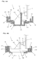
- Fig. 4A is a sectional view showing the electronic device including the surface pressing button, taken along line X-X in Fig. 2
- Fig. 4B is a sectional view showing the electronic device including the surface pressing button, taken along line Y-Y in Fig. 2.
- the base 112 of the surface pressing part 11 is in contact with the back surface 20 of the front panel 2.
- the distal end 111 of the surface pressing part 11 is prevented from projecting from the front panel 2 too much.
- the stopper hole 135 of the auxiliary supporting part 132 has a configuration in which its front surface is open, and the projection 113 is also in contact with the back surface 20 of the front panel 2.
- the switch pressing part 12 is connected to a back surface 110 of the surface pressing part 11.
- the switch pressing part 12 has a configuration in which it extends into the inside of the DVD player, and it is connected to the surface pressing part 11 and has a bottom plate 121 pressing a switch 4, and a reinforcing plate 122 integrally mounted on the center of the bottom plate 121 and connected to the surface pressing part 11.
- the switch 4 is mounted on a substrate 3 on the side of the switch pressing part 12. A small distance is formed between the switch 4 and the switch pressing part 12.
- the base 112 is supported by the supporting part 13 so as to be cantilevered through the hinge 14.
- the hinge 14 has a small thickness in compared with the other parts of the surface pressing button 1.
- the through hole 140 is formed in the center of the hinge and rigidity (flexibility) of the hinge 14 is adjusted when the thickness of the hinge itself and a size of the through hole 140 are adjusted.
- the boss 22 penetrating the boss hole 133 of the supporting part 13 is formed on the back surface 20 of the front panel 2.
- the boss 22 penetrates the boss hole 133 of the supporting part 13 and a projecting portion from the boss hole 133 is fused and welded to the boss hole 133.
- the surface pressing button 1 can be fixed to the back surface of the front panel 2.
- the hinge 14 When the distal end 111 of the surface pressing part 11 of the surface pressing button 1 is pressed from the outside of the front panel 2, the hinge 14 is bent and the surface pressing part 11 and the switch pressing part 12 are turned around the hinge 14. When the surface pressing part 11 and the switch pressing part 12 are turned, the bottom plate 121 of the switch pressing part 12 presses the switch 4. At this time, when the pressing part 11 is turned more than a predetermined range, the projection 113 formed in the surface pressing part 11 and inserted into the stopper 135 of the supporting part 13 comes in contact with the stopper 136 and the movement is stopped.
- the projection 113 comes into contact with the stopper 136. Therefore, when the switch 4 is pressed, the bottom plate 121 of the switch pressing part 12 is prevented from applying a strong force to the switch 4. Thus, since the switch 4 can be prevented from being damaged and the like, the surface pressing button 1 can be used for a long period of time. In addition, since the turning angle of the surface pressing part 11 is stopped at the certain angle, the hinge 14 can be prevented from being bent too much and prevented from being damaged by fatigue.
- the surface pressing button 1 When the surface pressing button 1 is mounted on the back surface 20 of the front panel 2, it can be mounted thereon such a manner that the distal end 111 of the surface pressing part 11 may be inserted into the through hole 21 of the front panel 2 and the boss 22 provided on the back surface 20 of the front panel 2 may be fit in the boss hole 133 provided in the supporting part 13 of the surface pressing button 1.
- the surface pressing button 1 when the surface pressing button 1 is mounted on each member of the front panel 2, unreasonable force is prevented from being applied. As a result, the mounting process is performed so that a sufficient ability can be provided without damaging the surface pressing button 1 and the front panel 2.
- the surface pressing button 1 can be easily mounted on the back surface 20 of the front panel 2, manufacturing steps and its time can be reduced. In addition, since nothing hinders the surface pressing button 1 when it is mounted, the surface pressing button 1 and the front panel 2 can be prevented from being deformed or damaged due to unreasonable force applied to each part of them when they are repeatedly mounted and dismounted for being positioned.
- Fig. 5 is a sectional view showing another example of the surface pressing button according to the present invention.
- a surface pressing button 1g shown in Fig. 5 is the same as the surface pressing button 1 shown in Fig. 2 and the like except for a switch pressing part 12g, in which the same numeral numbers are allotted to the same parts substantially.
- the switch pressing part 12g of the surface pressing button 1 shown in Fig. 5 has a configuration in which it extends from a back surface of a surface pressing part 11.
- the switch pressing part 12g is formed so that a switch 4 is pressed by an end part 121g which is not connected to the surface pressing part 11.
- a thickness of the electronic device can be reduced.
- buttons 1 include the power supply button 1p, the stop button 1a, the playback button 1b, and the medium ejection button 1c have been described according to the present invention; however, the present invention is not limited thereto and the number of buttons may be less than four or more than four.
- the DVD player which plays the DVD medium is used as the electronic device in the aforementioned embodiment; however, the present invention is not limited thereto.
- the present invention can be applied to an electronic device which is operated with surface pressing buttons (a VTR, a CD, a TV receiver, for example).
- the surface pressing button which can be surely and easily mounted on the back surface of the front panel without any complicated structure or addition of the component, and can be prevented from applying too much load to the switch, and the electronic device including such surface pressing button can be provided.
- the surface pressing button which can be easily mounted and manufactured in a short time at a low cost, and the electronic device including such surface pressing button can be provided.
- the switch since a large load is prevented from being applied from the surface pressing button to the switch, even when the surface pressing button is repeatedly pressed, the switch can be prevented from being damaged and the like, so that the surface pressing button and the electronic device can be used for a long time of period.
Landscapes
- Rotary Switch, Piano Key Switch, And Lever Switch (AREA)
- Push-Button Switches (AREA)
- Mechanisms For Operating Contacts (AREA)
Abstract
Description
- The present invention relates to a surface pressing button, and an electronic device including the surface pressing button, such as an audio device or a video device.
- An electronic device such as an audio device or a video device includes many surface pressing buttons to perform operations of the electronic device, on a front surface in many cases. In case that the electronic device is a DVD (Digital Versatile Disc) player, it includes surface pressing buttons capable of performing operations such as power ON/OFF, playback, stop, and disc ejection, so that the operation related to the surface pressing button can be performed by pressing the surface pressing button.
- Fig. 6 is a front view showing a DVD player which is an example of a conventional electronic device. A DVD player PM shown in Fig. 6 includes a slot Ih for a DVD medium, a
power supply button 91p, astop button 91a, a playback (pause)button 91b, amedium ejection button 91c to eject the DVD medium, and afront panel 92 on which the aforementioned buttons are provided. - Fig. 7A is a sectional view showing a push button of the electronic device shown in Fig. 6 and Fig. 7B is a sectional view showing a mounting part of the electronic device shown in Fig. 6. As shown in Figs. 7A and 7B, the
surface pressing button 91 is arranged so that asurface pressing part 911 may penetrate a throughhole 921 formed in thefront panel 92. Each of the foursurface pressing buttons 91 includes thesurface pressing part 911, aswitch pressing part 912 integrally formed with thesurface pressing part 911, and a supportingpart 913 to support thesurface pressing part 911 and theswitch pressing part 912. - The supporting
part 913 includes aboss hole 914 to which aboss 922 of thefront panel 92 which will be described later is inserted, and ahinge 915 which is connected to thesurface pressing part 911 and supported so as to be cantilevered. As shown in Figs. 7A and 7B, the supportingpart 913 supports the foursurface pressing buttons 91 arranged in line through thehinges 915. Aninclination preventing part 916 integrally formed with the supportingpart 913 to prevent thesurface pressing button 91 from inclining is formed between both ends and the adjacentsurface pressing buttons 91. Theboss hole 914 is also formed at the distal end of theinclination preventing part 916. - At this time, the
boss 922 penetrates theboss hole 914 formed in the supportingpart 913. An end of theboss 922 penetrating theboss hole 914 is heated to be fused and welded together to be fixed to theboss hole 914. - A
substrate 93 is provided on the side of theswitch pressing part 912 of thesurface pressing button 91, and aswitch 94 is also provided on the side of theswitch pressing part 912. Theswitch 94 is mounted on thesubstrate 93 and a small space is formed between theswitch 94 and theswitch pressing part 912. - When the
surface pressing button 91 presses thesurface pressing part 911, thehinge 915 of the supportingpart 913 bends, and an end of theswitch pressing part 912 is moved downward. Theswitch 94 is arranged in the moving direction of the end of theswitch pressing part 912. Thus, when theswitch pressing part 912 is moved downward, theswitch 94 is pressed by theswitch pressing part 912. - When the
surface pressing button 91 is pressed by strong force, theswitch 94 receives a large load from theswitch pressing part 912 and it could be damaged. In order to prevent the strong force from being applied to theswitch 94, thefront panel 92 includes ahook 923 to prevent an end opposite to thehinge 913 of thesurface pressing part 911 from being moved too much. Thehook 923 is formed adjacent to the throughhole 921 as shown in Fig. 7A. Thehook 923 is integrally formed with thefront panel 92. When thehook 923 engages with thesurface pressing part 911, thesurface pressing part 911 and theswitch pressing part 912 are prevented from being turned. - When the
surface pressing part 911 of thesurface pressing button 91 is pressed, thesurface pressing part 911 and theswitch pressing part 912 are turned around thehinge 913 for a certain amount and then the end of thesurface pressing part 911 comes into contact with thehook 923 and it is stopped. Thus, a large load is prevented from being applied to theswitch 94. - Japanese Unexamined Utility Model Publication No. 06-9023 (1994) discloses that a stopper rib is formed on a switch knob and, when the switch knob is pressed, the stopper rib abuts on a substrate holder to restrict an operation of the switch knob.
- Japanese Unexamined Patent Publication No. 2004-39324 discloses that a stopper is provided on each side of a pressing part and, when a button is pressed, the stopper comes into contact with a substrate and prevents the button from being pressed more than needs.
- The
surface pressing button 91 includes the supportingpart 913 and theboss hole 914 formed at the distal end of theinclination preventing part 916 which extends from the supportingpart 913. When thesurface pressing button 91 is mounted on thefront panel 92, theboss 922 is inserted into the eachboss hole 914. However, since thehook 923 which engages with thesurface pressing part 911 to restrict the movement of thesurface pressing part 911 is mounted on a position close to the throughhole 921 in thefront panel 92, when thesurface pressing button 91 is mounted, thesurface pressing part 911 comes into contact with thehook 923 also, so that it is difficult to mount thesurface pressing button 91 on thefront panel 92. - In case that the
hook 923 is formed of a material having a certain degree of flexibility, when thesurface pressing button 91 is mounted on thefront panel 92, thehook 923 is bent and thesurface pressing part 911 can easily engage with the throughhole 921. However, since thehook 923 is flexible, it cannot support a force applied from thesurface pressing part 911 sufficiently in some cases. - Although it may be considered that the
hook 923 and thefront panel 92 are manufactured separately and after thesurface pressing button 91 is mounted on thefront panel 92, thehook 923 is mounted, in this case, it is troublesome to mount thehook 923 and thehook 923 cannot support the force applied from thesurface pressing button 911 in some cases. - Although it may be considered that lengths of the
boss 922 and theboss hole 914 are shortened, some play is provided between theboss 922 and theboss hole 914 and thesurface pressing button 91 is tilted when it is mounted, in this case, thesurface pressing button 91 could be unstably fixed because the lengths of theboss 922 and theboss hole 914 are shortened. - The present invention has been made in order to solve the aforementioned problems and it is an object of the present invention to provide a surface pressing button which can be surely and easily mounted on a back surface of a front panel and prevent a switch from receiving a large load, and an electronic device including the surface pressing button.
- In order to achieve the aforementioned object, the present invention provides an electronic device including a front panel in which a through hole is formed, and a surface pressing button which is mounted on a back surface of the front panel and presses a switch. Herein, the surface pressing button includes a surface pressing part a portion of which is exposed from the through hole of the front panel, a switch pressing part which is integrally formed with the surface pressing part, a supporting part which supports the surface pressing part, and a hinge which connects the surface pressing part to the supporting part. The surface pressing part includes a projection which projects from an end on a side opposite to an end connected to the hinge. The supporting part includes a supporting frame which is in contact with the front panel and supports the surface pressing part through the hinge, an auxiliary supporting frame which is in contact with the front panel and is formed opposed to the supporting frame across the surface pressing part, a boss hole which is formed in each of the supporting frame and the auxiliary supporting frame, and is fitted and welded to a boss formed on the back surface of the front panel, and a reinforcing part which connects the supporting frame to the auxiliary supporting frame. The auxiliary supporting frame includes a stopper hole in which a portion on the side of the front panel is open, and a portion of the projection is provided, and a stopper which restricts movement of the projection, at the opposite end of the opening of the stopper hole.
- According to this configuration, since the projection, the stopper hole, and the stopper are integrally formed, the surface pressing button can be smoothly mounted on the front panel.
- In addition, according to this configuration, since the projection, the stopper hole, and the stopper are integrally formed, the surface pressing part of the surface pressing button can be promptly and accurately arranged in the through hole of the front panel.
- According to the aforementioned configuration, a plurality of surface pressing parts may be provided, and the supporting part may support the plurality of surface pressing parts arranged in line. In addition, according to the aforementioned configuration, the switch pressing part may press a switch at the opposite end of the surface pressing part, and the switch pressing part may be turned around the hinge to press the switch.
- In order to achieve the aforementioned object, the present invention also provides a surface pressing button mounted on a back surface of a front panel in which a through hole is formed. The surface pressing button includes a surface pressing part in which a portion thereof is exposed from the through hole of the front panel, a switch pressing part which is integrally formed with the surface pressing part, a supporting part which supports the surface pressing part, and a hinge which connects the surface pressing part to the supporting part. Herein, the surface pressing part includes a projection which projects from an end on a side opposite to an end connected to the hinge. The supporting part includes a supporting frame which is in contact with the front panel and supports the surface pressing part through the hinge, an auxiliary supporting frame which is in contact with the front panel and is formed opposed to the supporting frame across the surface pressing part, a boss hole which is formed in each of the supporting frame and the auxiliary supporting frame, and is fitted and welded to a boss formed on the back surface of the front panel, and a reinforcing part which connects the supporting frame to the auxiliary supporting frame. The auxiliary supporting frame includes a stopper hole in which a portion on the side of the front panel is open, and a portion of the projection is provided, and a stopper which restricts movement of the projection, at the opposite end of the opening of the stopper hole.
- According to this configuration, since the projection, the stopper hole, and the stopper are integrally formed, the surface pressing button can be smoothly mounted on the front panel.
- In addition, according to this configuration, since the projection, the stopper hole, and the stopper are integrally formed, the surface pressing part of the surface pressing button can be promptly and accurately arranged in the through hole of the front panel.
- According to the aforementioned configuration, a plurality of surface pressing parts may be provided, and the supporting part may support the plurality of surface pressing parts arranged in line.
- In addition, according to the aforementioned configuration, the switch pressing part may press a switch at the opposite end of the surface pressing part, and the switch pressing part may be turned around the hinge to press the switch.
- These and other objects and features of the present invention will become more apparent from the following detailed description of the present invention when taken in conjunction with the following accompanying drawings:
- Fig. 1 is a front view showing an example of an electronic device according to the present invention;
- Fig. 2 is a front view showing surface pressing buttons according to the present invention;
- Fig. 3 is a side view showing the surface pressing buttons shown in Fig. 2;
- Fig. 4A is a sectional view showing the electronic device including the surface pressing button, taken along line X-X in Fig. 2;
- Fig. 4B is a sectional view showing the electronic device including the surface pressing button, taken along line Y-Y in Fig. 2;
- Fig. 5 is a sectional view showing another example of the surface pressing button according to the present invention;
- Fig. 6 is a front view showing an example of a conventional electronic device;
- Fig. 7A is a sectional view showing a surface pressing button of the electronic device shown in Fig. 6; and
- Fig. 7B is a sectional view showing a mounting part of the electronic device shown in Fig. 6.
- Hereinafter, an embodiment will be described with reference to the drawings. Fig. 1 is a front view showing an example of an electronic device according to the present invention. An electronic device shown in Fig. 1 is a DVD player; however, the present invention is not limited thereto. The DVD player PL shown in Fig. 1 includes a slot Ih for a DVD medium, a power supply button 1 (1p), a stop button 1 (1a), a playback (pause) button 1 (1b), a medium ejection button 1 (1c) to eject the DVD medium, and a
front panel 2. - Each of the
power supply button 1p, the stop button 1a, theplayback button 1b and themedium ejection button 1c is pressed to perform an operation related to each button. Throughholes 21 are formed in thefront panel 2 and therespective buttons - Fig. 2 is a front view showing the surface pressing buttons according to the present invention, and Fig. 3 is a side view showing the surface pressing buttons shown in Fig. 2. The
surface pressing buttons 1 include thepower supply button 1p, the stop button 1a, theplayback button 1b and themedium ejection button 1c. Each button has the same constitution and includes asurface pressing part 11 penetrating the throughhole 21 of thefront panel 2, and aswitch pressing part 12 integrally connected to thesurface pressing part 11. A manufacturing method of thesurface pressing button 1 is an integral molding of resin in this example; however, the present invention is not limited thereto. - The
surface pressing button 1 includes a supportingpart 13, and the supportingpart 13 is connected to thesurface pressing part 11 through ahinge 14. As shown in Fig. 2, thesurface pressing part 11 has adistal end 111 penetrating the throughhole 21 of thefront panel 2, abase 112 preventing thesurface pressing button 11 from projecting from the throughhole 21 too much and connected to thehinge 14, and aprojection 113 connected to an opposite side of the base 112 connected to thehinge 14. - The supporting
part 13 includes a supportingframe 131 supporting the adjacentsurface pressing parts 11 and theswitch pressing parts 12 arranged in line, an auxiliary supportingframe 132 formed on a side opposite to the supportingframe 131 across the surface pressing part 11 (at a position opposed to the supporting frame across the surface pressing part 11), aboss hole 133 in which aboss 22 formed on aback surface 20 of thefront panel 2 as will be described below is to be externally fitted, and a reinforcingpart 134 connecting the supportingframe 131 to the auxiliary supportingframe 132. - The auxiliary supporting
frame 132 has astopper hole 135 to which a portion of theprojection 113 of thesurface pressing part 11 is inserted. Thestopper hole 135 is open in a direction that thesurface pressing button 1 is mounted on thefront panel 2, and astopper 136 is formed on its opposite side. - Five boss holes 133 are provided in each of the supporting
frame 131 and the auxiliary supportingframe 132, that is, tenboss holes 133 are provided in total; however, the present invention is not limited thereto. The boss holes 133 of the supportingframe 131 are formed at both ends and between the hinges 14. The boss holes 133 of theauxiliary frame 132 are formed at both ends and between the stopper holes 135. - As described above, the reinforcing
parts 134 connect the supportingframe 131 to the auxiliary supportingframe 132 and they are formed at both ends and between thepower supply button 1p and the stop button 1a and between theplayback button 1b and themedium ejection button 1c. In addition, although the present invention is not limited to the above, a component can be arranged variously so that thesurface pressing button 1 may have some strength. In addition, as shown in Fig. 2, a throughhole 140 is formed in the center of thehinge 14. - Fig. 4A is a sectional view showing the electronic device including the surface pressing button, taken along line X-X in Fig. 2, and Fig. 4B is a sectional view showing the electronic device including the surface pressing button, taken along line Y-Y in Fig. 2. As shown in Fig. 4A, the
base 112 of thesurface pressing part 11 is in contact with theback surface 20 of thefront panel 2. When thebase 112 is in contact with theback surface 20 of thefront panel 2, thedistal end 111 of thesurface pressing part 11 is prevented from projecting from thefront panel 2 too much. In addition, thestopper hole 135 of the auxiliary supportingpart 132 has a configuration in which its front surface is open, and theprojection 113 is also in contact with theback surface 20 of thefront panel 2. - As shown in Figs. 4A and 4B, the
switch pressing part 12 is connected to aback surface 110 of thesurface pressing part 11. Theswitch pressing part 12 has a configuration in which it extends into the inside of the DVD player, and it is connected to thesurface pressing part 11 and has abottom plate 121 pressing aswitch 4, and a reinforcingplate 122 integrally mounted on the center of thebottom plate 121 and connected to thesurface pressing part 11. In addition, theswitch 4 is mounted on asubstrate 3 on the side of theswitch pressing part 12. A small distance is formed between theswitch 4 and theswitch pressing part 12. - The
base 112 is supported by the supportingpart 13 so as to be cantilevered through thehinge 14. As shown in Fig. 4A, thehinge 14 has a small thickness in compared with the other parts of thesurface pressing button 1. In addition, as described above, the throughhole 140 is formed in the center of the hinge and rigidity (flexibility) of thehinge 14 is adjusted when the thickness of the hinge itself and a size of the throughhole 140 are adjusted. - As shown in Fig. 4B, the
boss 22 penetrating theboss hole 133 of the supportingpart 13 is formed on theback surface 20 of thefront panel 2. Theboss 22 penetrates theboss hole 133 of the supportingpart 13 and a projecting portion from theboss hole 133 is fused and welded to theboss hole 133. When theboss 22 and theboss hole 133 are welded, thesurface pressing button 1 can be fixed to the back surface of thefront panel 2. - When the
distal end 111 of thesurface pressing part 11 of thesurface pressing button 1 is pressed from the outside of thefront panel 2, thehinge 14 is bent and thesurface pressing part 11 and theswitch pressing part 12 are turned around thehinge 14. When thesurface pressing part 11 and theswitch pressing part 12 are turned, thebottom plate 121 of theswitch pressing part 12 presses theswitch 4. At this time, when thepressing part 11 is turned more than a predetermined range, theprojection 113 formed in thesurface pressing part 11 and inserted into thestopper 135 of the supportingpart 13 comes in contact with thestopper 136 and the movement is stopped. - Thus, when the turning angle of the
surface pressing part 11 of thesurface pressing button 1 reaches a certain angle, theprojection 113 comes into contact with thestopper 136. Therefore, when theswitch 4 is pressed, thebottom plate 121 of theswitch pressing part 12 is prevented from applying a strong force to theswitch 4. Thus, since theswitch 4 can be prevented from being damaged and the like, thesurface pressing button 1 can be used for a long period of time. In addition, since the turning angle of thesurface pressing part 11 is stopped at the certain angle, thehinge 14 can be prevented from being bent too much and prevented from being damaged by fatigue. - When the
surface pressing button 1 is mounted on theback surface 20 of thefront panel 2, it can be mounted thereon such a manner that thedistal end 111 of thesurface pressing part 11 may be inserted into the throughhole 21 of thefront panel 2 and theboss 22 provided on theback surface 20 of thefront panel 2 may be fit in theboss hole 133 provided in the supportingpart 13 of thesurface pressing button 1. Thus, when thesurface pressing button 1 is mounted on each member of thefront panel 2, unreasonable force is prevented from being applied. As a result, the mounting process is performed so that a sufficient ability can be provided without damaging thesurface pressing button 1 and thefront panel 2. - Thus, since the
surface pressing button 1 can be easily mounted on theback surface 20 of thefront panel 2, manufacturing steps and its time can be reduced. In addition, since nothing hinders thesurface pressing button 1 when it is mounted, thesurface pressing button 1 and thefront panel 2 can be prevented from being deformed or damaged due to unreasonable force applied to each part of them when they are repeatedly mounted and dismounted for being positioned. - Fig. 5 is a sectional view showing another example of the surface pressing button according to the present invention. A surface pressing button 1g shown in Fig. 5 is the same as the
surface pressing button 1 shown in Fig. 2 and the like except for aswitch pressing part 12g, in which the same numeral numbers are allotted to the same parts substantially. - The
switch pressing part 12g of thesurface pressing button 1 shown in Fig. 5 has a configuration in which it extends from a back surface of asurface pressing part 11. Theswitch pressing part 12g is formed so that aswitch 4 is pressed by anend part 121g which is not connected to thesurface pressing part 11. As shown in Fig. 5, in case of an electronic device in which thesurface pressing button 1 and asubstrate 3 are opposed, when theend 121g of theswitch pressing part 12g which is not connected to thesurface pressing part 11 is used to press theswitch 4, a thickness of the electronic device can be reduced. - In addition, the four
surface pressing buttons 1 include thepower supply button 1p, the stop button 1a, theplayback button 1b, and themedium ejection button 1c have been described according to the present invention; however, the present invention is not limited thereto and the number of buttons may be less than four or more than four. - The DVD player which plays the DVD medium is used as the electronic device in the aforementioned embodiment; however, the present invention is not limited thereto. The present invention can be applied to an electronic device which is operated with surface pressing buttons (a VTR, a CD, a TV receiver, for example).
- According to the present invention described with reference to the aforementioned embodiment, the surface pressing button which can be surely and easily mounted on the back surface of the front panel without any complicated structure or addition of the component, and can be prevented from applying too much load to the switch, and the electronic device including such surface pressing button can be provided.
- In addition, according to the present invention, since positioning precision is improved without addition of the component, the surface pressing button which can be easily mounted and manufactured in a short time at a low cost, and the electronic device including such surface pressing button can be provided.
- Furthermore, according to the present invention, since a large load is prevented from being applied from the surface pressing button to the switch, even when the surface pressing button is repeatedly pressed, the switch can be prevented from being damaged and the like, so that the surface pressing button and the electronic device can be used for a long time of period.
- Features, components and specific details of the structures of the above-described embodiments may be exchanged or combined to form further embodiments optimized for the respective application. As far as those modifications are readily apparent for an expert skilled in the art they shall be disclosed implicitly by the above description without specifying explicitly every possible combination, for the sake of conciseness of the present description.
Claims (5)
- A surface pressing button (1) mounted on a back surface of a front panel (2) in which a through hole (21) is formed, comprising:a surface pressing part (11) in which a portion thereof is exposed from the through hole (21) of the front panel (2); a switch pressing part (12) which is integrally formed with the surface pressing part (11); a supporting part (13) which supports the surface pressing part (11); and a hinge (14) which connects the surface pressing part (11) to the supporting part (13), characterized in that the surface pressing part (11) includes a projection (113) which projects from an end on a side opposite to an end connected to the hinge (14), the supporting part (13) includes: a supporting frame (131) which is in contact with the front panel (2) and supports the surface pressing part (11) through the hinge; an auxiliary supporting frame (132) which is in contact with the front panel (2) and is formed opposed to the supporting frame (132) across the surface pressing part (11); a boss hole (133) which is formed in each of the supporting frame (131) and the auxiliary supporting frame (132), and is.fitted and welded to a boss (22) formed on the back surface (20) of the front panel (2); and a reinforcing part (134) which connects the supporting frame (131) to the auxiliary supporting frame (132), andthe auxiliary supporting frame (132) includes: a stopper hole (135) in which a portion on the side of the front panel (2) is open, and a portion of the protection (113) is provided; and a stopper (136) which restricts movement of the projection (113), at the opposite end of the opening of the stopper hole (135).
- The surface pressing button according to claim 1, characterized
in that
a plurality of surface pressing parts (11) are provided, and the supporting part (13) supports the plurality of surface pressing parts (11) arranged in line. - The surface pressing button according to claim 1 or 2,
characterized in that
the switch pressing part (12) presses a switch (4) at the opposite end of the surface pressing part (11). - The surface pressing button according to claim 1 or 2,
characterized in that
the switch pressing part (12) is turned around the hinge (14) to press the switch (4). - An electronic device comprising: a front panel (2) in which a through hole (21) is formed; and the surface pressing button (1) according to any one of the claims 1 to 4.
Applications Claiming Priority (1)
| Application Number | Priority Date | Filing Date | Title |
|---|---|---|---|
| JP2005031592A JP2006221845A (en) | 2005-02-08 | 2005-02-08 | Face push button and electronic equipment |
Publications (3)
| Publication Number | Publication Date |
|---|---|
| EP1688977A2 true EP1688977A2 (en) | 2006-08-09 |
| EP1688977A3 EP1688977A3 (en) | 2007-11-14 |
| EP1688977B1 EP1688977B1 (en) | 2008-11-19 |
Family
ID=36228730
Family Applications (1)
| Application Number | Title | Priority Date | Filing Date |
|---|---|---|---|
| EP06002551A Expired - Lifetime EP1688977B1 (en) | 2005-02-08 | 2006-02-08 | Surface pressing button and electronic device including the same |
Country Status (5)
| Country | Link |
|---|---|
| US (1) | US7098417B1 (en) |
| EP (1) | EP1688977B1 (en) |
| JP (1) | JP2006221845A (en) |
| CN (1) | CN100492567C (en) |
| DE (1) | DE602006003670D1 (en) |
Cited By (1)
| Publication number | Priority date | Publication date | Assignee | Title |
|---|---|---|---|---|
| EP2164082A3 (en) * | 2008-09-10 | 2010-08-04 | Arcadyan Technology Corp. | Antenna module |
Families Citing this family (13)
| Publication number | Priority date | Publication date | Assignee | Title |
|---|---|---|---|---|
| TWI250798B (en) * | 2004-10-19 | 2006-03-01 | Coretronic Corp | Pushbutton protection device of electronic product |
| CN2791838Y (en) * | 2004-11-13 | 2006-06-28 | 鸿富锦精密工业(深圳)有限公司 | Button device |
| JP2007115499A (en) * | 2005-10-20 | 2007-05-10 | Orion Denki Kk | Push-button device |
| US7371984B2 (en) * | 2005-10-21 | 2008-05-13 | Lg Electronics Inc. | Button assembly of dishwasher |
| TWM286988U (en) * | 2005-10-27 | 2006-02-01 | Inventec Appliances Corp | Improved structure of reciprocated-type switch |
| US20070095637A1 (en) * | 2005-10-31 | 2007-05-03 | Hettinger Steve E | Appliance knob mounting system and method |
| CN100493306C (en) * | 2005-12-22 | 2009-05-27 | 群康科技(深圳)有限公司 | Housing device with key structure |
| CN2886781Y (en) * | 2006-02-10 | 2007-04-04 | 鸿富锦精密工业(深圳)有限公司 | Power supply key module structure |
| JP2009043100A (en) * | 2007-08-09 | 2009-02-26 | Fujitsu Ltd | Medium drive unit and electronic device |
| CN101728625B (en) * | 2008-10-23 | 2012-11-14 | 智易科技股份有限公司 | Antenna module |
| JP2013037989A (en) | 2011-08-10 | 2013-02-21 | Yazaki Corp | Socket |
| JP5842527B2 (en) * | 2011-10-14 | 2016-01-13 | オムロン株式会社 | Pushbutton switch and electronic device using the same |
| CN204792984U (en) * | 2015-07-06 | 2015-11-18 | 宁波艾森饰品有限公司 | Battery case and applied necklace that has this battery case |
Citations (2)
| Publication number | Priority date | Publication date | Assignee | Title |
|---|---|---|---|---|
| JPH0669023U (en) | 1993-03-15 | 1994-09-27 | 日野自動車工業株式会社 | Automotive knee protector |
| JP2004039324A (en) | 2002-07-01 | 2004-02-05 | Casio Comput Co Ltd | Key button |
Family Cites Families (10)
| Publication number | Priority date | Publication date | Assignee | Title |
|---|---|---|---|---|
| JPS57152725U (en) * | 1981-03-20 | 1982-09-25 | ||
| JPH069023U (en) | 1992-07-09 | 1994-02-04 | 船井電機株式会社 | Tact switch knob structure |
| JPH09115376A (en) * | 1995-10-23 | 1997-05-02 | Tokai Rika Co Ltd | Control device for vehicle air conditioner |
| MY122430A (en) * | 1999-12-08 | 2006-04-29 | Sony Corp | Electronic equipment and transmission device of button device used therein |
| JP2001345030A (en) * | 2000-05-31 | 2001-12-14 | Tokai Rika Co Ltd | Switch knob and method of manufacturing switch knob |
| JP2002190233A (en) * | 2000-12-19 | 2002-07-05 | Pioneer Electronic Corp | Switch operation body |
| JP3838170B2 (en) * | 2002-07-08 | 2006-10-25 | 株式会社デンソー | Switch structure |
| JP2004103490A (en) * | 2002-09-12 | 2004-04-02 | Orion Denki Kk | Mounting structure for operating button of electric equipment |
| JP3871136B2 (en) * | 2003-10-03 | 2007-01-24 | 船井電機株式会社 | Switch device |
| KR100605257B1 (en) * | 2004-07-22 | 2006-07-28 | 삼성전자주식회사 | Operation button support device of electronic device and electronic device |
-
2005
- 2005-02-08 JP JP2005031592A patent/JP2006221845A/en active Pending
-
2006
- 2006-02-07 US US11/348,480 patent/US7098417B1/en not_active Expired - Fee Related
- 2006-02-08 DE DE602006003670T patent/DE602006003670D1/en not_active Expired - Lifetime
- 2006-02-08 CN CNB2006100047376A patent/CN100492567C/en not_active Expired - Fee Related
- 2006-02-08 EP EP06002551A patent/EP1688977B1/en not_active Expired - Lifetime
Patent Citations (2)
| Publication number | Priority date | Publication date | Assignee | Title |
|---|---|---|---|---|
| JPH0669023U (en) | 1993-03-15 | 1994-09-27 | 日野自動車工業株式会社 | Automotive knee protector |
| JP2004039324A (en) | 2002-07-01 | 2004-02-05 | Casio Comput Co Ltd | Key button |
Cited By (2)
| Publication number | Priority date | Publication date | Assignee | Title |
|---|---|---|---|---|
| EP2164082A3 (en) * | 2008-09-10 | 2010-08-04 | Arcadyan Technology Corp. | Antenna module |
| US8305288B2 (en) | 2008-09-10 | 2012-11-06 | Arcadyan Technology Corporation | Antenna module |
Also Published As
| Publication number | Publication date |
|---|---|
| DE602006003670D1 (en) | 2009-01-02 |
| EP1688977B1 (en) | 2008-11-19 |
| JP2006221845A (en) | 2006-08-24 |
| US7098417B1 (en) | 2006-08-29 |
| CN1822269A (en) | 2006-08-23 |
| EP1688977A3 (en) | 2007-11-14 |
| CN100492567C (en) | 2009-05-27 |
| US20060175186A1 (en) | 2006-08-10 |
Similar Documents
| Publication | Publication Date | Title |
|---|---|---|
| EP1688977B1 (en) | Surface pressing button and electronic device including the same | |
| US20080280477A1 (en) | IC socket | |
| US20040095718A1 (en) | System for latching and ejecting a modular component from an electronic device | |
| EP1352786B1 (en) | Electronic instrument | |
| US6005775A (en) | Circuit board mounting apparatus with inverted U-shaped mounting arms for mounting a circuit board | |
| US20060016675A1 (en) | Supporting device for control buttons of electronic instruments and electronic instruments adapting the same | |
| GB2328798A (en) | Knob assembly for use in electronic appliances | |
| KR20060042921A (en) | Recording medium mounting device | |
| JP2010251229A (en) | Electronics | |
| JP3930242B2 (en) | Electronics | |
| JP2000339947A (en) | Drawer type disk unit | |
| US20060020956A1 (en) | Data recording/reproducing apparatus | |
| JPH08264996A (en) | Flexible board jig | |
| US6599146B2 (en) | ZIF socket | |
| JP2001188953A (en) | Vending machine product unloading device | |
| JP2003338235A (en) | Slide switch and electronic device using the same | |
| US7326868B2 (en) | Button apparatus for disk drive | |
| JP3126685U (en) | Disk unit | |
| JP2003117192A (en) | Board mounting structure for ball and ball game machines | |
| KR100406950B1 (en) | Device for ejecting memory medium of portable device | |
| US20070089976A1 (en) | Push button device | |
| KR100246042B1 (en) | Car Audio System | |
| KR20040022323A (en) | Top loading door apparatus of audio | |
| JPH06302173A (en) | Operating button of electronic apparatus | |
| JPH06104354A (en) | IC socket |
Legal Events
| Date | Code | Title | Description |
|---|---|---|---|
| PUAI | Public reference made under article 153(3) epc to a published international application that has entered the european phase |
Free format text: ORIGINAL CODE: 0009012 |
|
| AK | Designated contracting states |
Kind code of ref document: A2 Designated state(s): AT BE BG CH CY CZ DE DK EE ES FI FR GB GR HU IE IS IT LI LT LU LV MC NL PL PT RO SE SI SK TR |
|
| AX | Request for extension of the european patent |
Extension state: AL BA HR MK YU |
|
| PUAL | Search report despatched |
Free format text: ORIGINAL CODE: 0009013 |
|
| AK | Designated contracting states |
Kind code of ref document: A3 Designated state(s): AT BE BG CH CY CZ DE DK EE ES FI FR GB GR HU IE IS IT LI LT LU LV MC NL PL PT RO SE SI SK TR |
|
| AX | Request for extension of the european patent |
Extension state: AL BA HR MK YU |
|
| RIC1 | Information provided on ipc code assigned before grant |
Ipc: H01H 13/14 20060101ALI20071006BHEP Ipc: H01H 13/70 20060101AFI20060511BHEP Ipc: H01H 21/24 20060101ALI20071006BHEP |
|
| 17P | Request for examination filed |
Effective date: 20080331 |
|
| GRAP | Despatch of communication of intention to grant a patent |
Free format text: ORIGINAL CODE: EPIDOSNIGR1 |
|
| AKX | Designation fees paid |
Designated state(s): DE FR GB |
|
| GRAS | Grant fee paid |
Free format text: ORIGINAL CODE: EPIDOSNIGR3 |
|
| GRAA | (expected) grant |
Free format text: ORIGINAL CODE: 0009210 |
|
| AK | Designated contracting states |
Kind code of ref document: B1 Designated state(s): DE FR GB |
|
| REG | Reference to a national code |
Ref country code: GB Ref legal event code: FG4D |
|
| REF | Corresponds to: |
Ref document number: 602006003670 Country of ref document: DE Date of ref document: 20090102 Kind code of ref document: P |
|
| PLBE | No opposition filed within time limit |
Free format text: ORIGINAL CODE: 0009261 |
|
| STAA | Information on the status of an ep patent application or granted ep patent |
Free format text: STATUS: NO OPPOSITION FILED WITHIN TIME LIMIT |
|
| 26N | No opposition filed |
Effective date: 20090820 |
|
| PGFP | Annual fee paid to national office [announced via postgrant information from national office to epo] |
Ref country code: FR Payment date: 20130301 Year of fee payment: 8 Ref country code: DE Payment date: 20130206 Year of fee payment: 8 Ref country code: GB Payment date: 20130207 Year of fee payment: 8 |
|
| REG | Reference to a national code |
Ref country code: DE Ref legal event code: R119 Ref document number: 602006003670 Country of ref document: DE |
|
| GBPC | Gb: european patent ceased through non-payment of renewal fee |
Effective date: 20140208 |
|
| REG | Reference to a national code |
Ref country code: FR Ref legal event code: ST Effective date: 20141031 |
|
| REG | Reference to a national code |
Ref country code: DE Ref legal event code: R119 Ref document number: 602006003670 Country of ref document: DE Effective date: 20140902 |
|
| PG25 | Lapsed in a contracting state [announced via postgrant information from national office to epo] |
Ref country code: FR Free format text: LAPSE BECAUSE OF NON-PAYMENT OF DUE FEES Effective date: 20140228 Ref country code: GB Free format text: LAPSE BECAUSE OF NON-PAYMENT OF DUE FEES Effective date: 20140208 Ref country code: DE Free format text: LAPSE BECAUSE OF NON-PAYMENT OF DUE FEES Effective date: 20140902 |