EP1688932A2 - Optical disk, optical disk drive and method of playing back an optical disk - Google Patents
Optical disk, optical disk drive and method of playing back an optical disk Download PDFInfo
- Publication number
- EP1688932A2 EP1688932A2 EP06100522A EP06100522A EP1688932A2 EP 1688932 A2 EP1688932 A2 EP 1688932A2 EP 06100522 A EP06100522 A EP 06100522A EP 06100522 A EP06100522 A EP 06100522A EP 1688932 A2 EP1688932 A2 EP 1688932A2
- Authority
- EP
- European Patent Office
- Prior art keywords
- sub
- data
- optical disk
- data unit
- errors
- Prior art date
- Legal status (The legal status is an assumption and is not a legal conclusion. Google has not performed a legal analysis and makes no representation as to the accuracy of the status listed.)
- Withdrawn
Links
Images


Classifications
-
- F—MECHANICAL ENGINEERING; LIGHTING; HEATING; WEAPONS; BLASTING
- F21—LIGHTING
- F21V—FUNCTIONAL FEATURES OR DETAILS OF LIGHTING DEVICES OR SYSTEMS THEREOF; STRUCTURAL COMBINATIONS OF LIGHTING DEVICES WITH OTHER ARTICLES, NOT OTHERWISE PROVIDED FOR
- F21V33/00—Structural combinations of lighting devices with other articles, not otherwise provided for
- F21V33/0064—Health, life-saving or fire-fighting equipment
-
- G—PHYSICS
- G11—INFORMATION STORAGE
- G11B—INFORMATION STORAGE BASED ON RELATIVE MOVEMENT BETWEEN RECORD CARRIER AND TRANSDUCER
- G11B20/00—Signal processing not specific to the method of recording or reproducing; Circuits therefor
- G11B20/10—Digital recording or reproducing
- G11B20/18—Error detection or correction; Testing, e.g. of drop-outs
-
- F—MECHANICAL ENGINEERING; LIGHTING; HEATING; WEAPONS; BLASTING
- F21—LIGHTING
- F21V—FUNCTIONAL FEATURES OR DETAILS OF LIGHTING DEVICES OR SYSTEMS THEREOF; STRUCTURAL COMBINATIONS OF LIGHTING DEVICES WITH OTHER ARTICLES, NOT OTHERWISE PROVIDED FOR
- F21V17/00—Fastening of component parts of lighting devices, e.g. shades, globes, refractors, reflectors, filters, screens, grids or protective cages
- F21V17/10—Fastening of component parts of lighting devices, e.g. shades, globes, refractors, reflectors, filters, screens, grids or protective cages characterised by specific fastening means or way of fastening
- F21V17/104—Fastening of component parts of lighting devices, e.g. shades, globes, refractors, reflectors, filters, screens, grids or protective cages characterised by specific fastening means or way of fastening using feather joints, e.g. tongues and grooves, with or without friction
-
- F—MECHANICAL ENGINEERING; LIGHTING; HEATING; WEAPONS; BLASTING
- F21—LIGHTING
- F21V—FUNCTIONAL FEATURES OR DETAILS OF LIGHTING DEVICES OR SYSTEMS THEREOF; STRUCTURAL COMBINATIONS OF LIGHTING DEVICES WITH OTHER ARTICLES, NOT OTHERWISE PROVIDED FOR
- F21V17/00—Fastening of component parts of lighting devices, e.g. shades, globes, refractors, reflectors, filters, screens, grids or protective cages
- F21V17/10—Fastening of component parts of lighting devices, e.g. shades, globes, refractors, reflectors, filters, screens, grids or protective cages characterised by specific fastening means or way of fastening
- F21V17/12—Fastening of component parts of lighting devices, e.g. shades, globes, refractors, reflectors, filters, screens, grids or protective cages characterised by specific fastening means or way of fastening by screwing
-
- G—PHYSICS
- G11—INFORMATION STORAGE
- G11B—INFORMATION STORAGE BASED ON RELATIVE MOVEMENT BETWEEN RECORD CARRIER AND TRANSDUCER
- G11B20/00—Signal processing not specific to the method of recording or reproducing; Circuits therefor
- G11B20/10—Digital recording or reproducing
- G11B20/12—Formatting, e.g. arrangement of data block or words on the record carriers
- G11B20/1217—Formatting, e.g. arrangement of data block or words on the record carriers on discs
-
- G—PHYSICS
- G11—INFORMATION STORAGE
- G11B—INFORMATION STORAGE BASED ON RELATIVE MOVEMENT BETWEEN RECORD CARRIER AND TRANSDUCER
- G11B7/00—Recording or reproducing by optical means, e.g. recording using a thermal beam of optical radiation by modifying optical properties or the physical structure, reproducing using an optical beam at lower power by sensing optical properties; Record carriers therefor
- G11B7/004—Recording, reproducing or erasing methods; Read, write or erase circuits therefor
- G11B7/005—Reproducing
- G11B7/0053—Reproducing non-user data, e.g. wobbled address, prepits, BCA
-
- G—PHYSICS
- G11—INFORMATION STORAGE
- G11B—INFORMATION STORAGE BASED ON RELATIVE MOVEMENT BETWEEN RECORD CARRIER AND TRANSDUCER
- G11B7/00—Recording or reproducing by optical means, e.g. recording using a thermal beam of optical radiation by modifying optical properties or the physical structure, reproducing using an optical beam at lower power by sensing optical properties; Record carriers therefor
- G11B7/007—Arrangement of the information on the record carrier, e.g. form of tracks, actual track shape, e.g. wobbled, or cross-section, e.g. v-shaped; Sequential information structures, e.g. sectoring or header formats within a track
- G11B7/00736—Auxiliary data, e.g. lead-in, lead-out, Power Calibration Area [PCA], Burst Cutting Area [BCA], control information
-
- A—HUMAN NECESSITIES
- A61—MEDICAL OR VETERINARY SCIENCE; HYGIENE
- A61N—ELECTROTHERAPY; MAGNETOTHERAPY; RADIATION THERAPY; ULTRASOUND THERAPY
- A61N5/00—Radiation therapy
- A61N5/06—Radiation therapy using light
- A61N2005/0658—Radiation therapy using light characterised by the wavelength of light used
- A61N2005/0659—Radiation therapy using light characterised by the wavelength of light used infrared
- A61N2005/066—Radiation therapy using light characterised by the wavelength of light used infrared far infrared
-
- G—PHYSICS
- G11—INFORMATION STORAGE
- G11B—INFORMATION STORAGE BASED ON RELATIVE MOVEMENT BETWEEN RECORD CARRIER AND TRANSDUCER
- G11B20/00—Signal processing not specific to the method of recording or reproducing; Circuits therefor
- G11B20/10—Digital recording or reproducing
- G11B20/12—Formatting, e.g. arrangement of data block or words on the record carriers
- G11B20/1217—Formatting, e.g. arrangement of data block or words on the record carriers on discs
- G11B2020/1218—Formatting, e.g. arrangement of data block or words on the record carriers on discs wherein the formatting concerns a specific area of the disc
- G11B2020/122—Burst cutting area [BCA]
-
- G—PHYSICS
- G11—INFORMATION STORAGE
- G11B—INFORMATION STORAGE BASED ON RELATIVE MOVEMENT BETWEEN RECORD CARRIER AND TRANSDUCER
- G11B20/00—Signal processing not specific to the method of recording or reproducing; Circuits therefor
- G11B20/10—Digital recording or reproducing
- G11B20/12—Formatting, e.g. arrangement of data block or words on the record carriers
- G11B2020/1264—Formatting, e.g. arrangement of data block or words on the record carriers wherein the formatting concerns a specific kind of data
- G11B2020/1265—Control data, system data or management information, i.e. data used to access or process user data
- G11B2020/1287—Synchronisation pattern, e.g. VCO fields
-
- G—PHYSICS
- G11—INFORMATION STORAGE
- G11B—INFORMATION STORAGE BASED ON RELATIVE MOVEMENT BETWEEN RECORD CARRIER AND TRANSDUCER
- G11B2220/00—Record carriers by type
- G11B2220/20—Disc-shaped record carriers
- G11B2220/25—Disc-shaped record carriers characterised in that the disc is based on a specific recording technology
- G11B2220/2537—Optical discs
Definitions
- the present invention relates to an optical disk, an optical disk drive, and a method of playing back an optical disk. More particularly, the invention relates to an optical disk having a burst cutting area (BCA) in which data can be recorded, and to improvements to means and method for reproducing data form the BCA.
- BCA burst cutting area
- a digital versatile disk i.e., a conventional optical disk
- Basic data that is used to play back the DVD is recorded in the BCA.
- the BCA has a track width and a bit length, both large enough to reproduce data from the DVD without adjusting the position of the optical head.
- the apparatus rotates the DVD at a predetermined speed.
- the optical head emitting a laser beam is moved in the radial direction of the DVD to the data-recording region of the DVD. Focus servo control is thereby performed in the data-recording region.
- the optical head then scans the BCA, reproducing the data recorded in the BCA.
- the data is used to reproduce ordinary data recorded in the data-recording region. No tracking servo control is performed to playback the BCA.
- the BCA is an inner circular track provided on the DVD.
- the data recorded in the BCA has a fixed data format.
- the conventional DVD is disadvantageous in two respects. First, if its BCA has prominent defects such as scratches, no DVD playback apparatuses can reproduce the data recorded in the BCA. Second, only a small part of the BCA holds data, with the remaining, greater part padded and not used. This invention has been made to eliminate these disadvantages.
- an optical disk that has a burst cutting area (BCA) having a data format.
- the data format comprises: a plurality of sub-data units, each having a preamble, data, an error-detecting code, error-correcting codes, a postamble and sync codes; and a code arranged between two adjacent sub-data units and coupling the two adjacent sub-data units.
- an optical disk drive for driving an optical disk of the type described above.
- the optical disk drive comprises: means for identifying a signal reproduced from the burst cutting area; extracting means for extracting a desired sub-data unit from the burst cutting area in accordance with an instruction supplied from an external apparatus; error-correcting means; error-detecting unit; and a controller for controlling the extracting means and informing a next circuit of generation of errros, when the error-detecting unit detects the errors in the sub-data unit extracted.
- a method of playing back an optical disk of the type described above comprises: identifying a signal reproduced from the burst cutting area; desiganting a sub-data unit to be extracted, in accrodance with the signal identified; extracting the sub-data unit designated; correcting the sub-data unit extracted; detecting errors in the sub-data unit corrected; determining whether a number of errors detected exceeds a preset value, from a result of the detecting errors; transmitting the data if the number of errors does not exceeds the preset value; and switching (S10) the sub-data unit to another sub-data unit to be extracted, if the the number of errors exceeds the preset value.
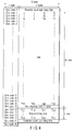
- FIG. 1 shows a data format of an optical disk according to this invention.
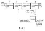
- FIG. 2 is a block diagram of an optical disk drive, which is another embodiment of the invention.
- FIG. 3 is a flowchart explaning a method of playing back an optical disk, which is still another embodiment of this invention.
- BCA data format of the latter will be first described, with reference to FIG. 4.
- the data recorded in the BCA includes a preamble, a postamble, data, sync codes, an error-detecting codes, and four error-correcting codes.
- Each sync code (1 byte) pertains to five bytes, including itselft.
- Sync code 0 is at the head of the BCA data format and is allocated to the preamble.
- the preamble consists of four bytes, each byte being 00 (hexadecimal).
- Sync codes 1 to 12 are allocated to each 16-byte data unit consisting of data and an error-detecting code.
- the data is apprently fixed at the amount of 188 bytes.
- Four sync codes 13 are allocated to the four error-correcting codes, respectively.
- Sync code 14 follows the fourth error-correcting code and is allocated to the postamble.
- the postamble consists of four bytes, each byte being 55 (hexadecimal).
- Sync code 15, or the last sync code, is the last item of the BCA data format.
- the conventional DVD playback apparatus detects the BCA upon receiving sync code 0 or both sync code 0 and preamble. Then, the apparatus uses sync codes 1 to 13, reading the data, error-detecting code and error-correcting codes and storing them in the memory provided in it. When the apparatus receives sync code 14, postamble, or sync code 15, or any combinations of these, it detects that the data, error-detecting code and error-correcting codes have been stored into the memory.
- the apparatus corrects the data stored in the memory. From the error-detecting code, the apparatus determines whether the data contains errors. If the data contains no errors, the data that has been corrected is supplied to a next circuit (not shown). If the data contains errors, the data indicating this is supplied to the external apparatus.
- the BCA of the conventional DVD is an inner circular track and can record 188 bytes at most. In practice, however, only a small part of the BCA is used, and the remaining, greater part is padded and not used. In view of this, the BCA of an optical disk according to this invention is so formatted as will be described below.
- the data format is composed of two sub-data units (100,200) (also called sub-data regions) and a coupling code (300) that couples the sub-data units (100,200). That is, the coupling code (300) arranged beween two adjacent sub-data units (100,200) couples these two adjacent sub-data units (100,200).
- each sub-data unit (100,200) is similar in structure to the BCA data format of the conventional DVD. Namely, each sub-data unit (100,200) contains a preamble (10a,10b), a postamble (11a,11b), data (12a,12b), sync codes (13a,13b), an error-detecting codes (14a,14b), and four error-correcting codes (15a,15b).
- Each sync code (1 byte) pertains to five bytes, including itself.
- Nine types of sync codes, i.e., code 0 to code 5 and codes 13 to 15, are available.
- sync codes are arranged, forming a column of bits, which is similar to the column illustrated in FIG. 4.
- sync code 0 is at the head and is allocated to the preamble.
- the preamble consists of four bytes, each byte being 00 (hexadecimal).
- Sync codes 1 to 5 are allocated to the data and the error-detecting code. More precisely, four sync codes of the same type are allocated to 16 bytes of data. Of four sync codes 5, however, the first three are allocated to 12 bytes of data, and the last is allocated to the error-detecting code (4 bytes).
- Sync code 14 follows the fourth error-correcting code and is allocated to the postamble. The postamble consists of four bytes, each byte being 55 (hexadecimal). Sync code 14 is the last item of the BCA data format of the sub-data unit.
- the two sub-data units are identical. In other words, their contents are identical.
- the coupling code coupling two sub-data units consists of four bytes, each byte being AA (hexadecimal).
- the sub-data units combined are similar to the BCA data format of the conventional DVD in that each sync code pertains five bytes, including itself.
- the four bytes forming the coupling code need not be all AA (hexadecimal).
- the coupling code needs only to differ from the preamble and the postamble. Nonetheless, it should better consist of four bytes, each being AA (hexadecimal). This is because it much differs from the postamble consisting of four bytes 55, each byte being 00 (hexadecimal). Namely, AA (10101010) is exactly inverse to 55 (10101010) in positions of 1s and 0s.
- the BCA data format has two sub-data units. Alternatively, it may have three or more sub-data units. If so, the sub-data units are reduced in size because the size of the BCA is fixed. In practice, it is desired that the format have two sub-data units.
- the sub-data units recorded in the BCA of the optical disk according to this invention are identical in basic structure to the BCA data format of the DVD.
- the conventional DVD playback apparatus can therefore reproduce one of the sub-data units recorded in the optical disk of this invention.
- the two sub-data units are identical in content. Nevertheless, they may differ in content in some cases. For example, only one of the sub-data units may contain the data representing the type of the disk, while both sub-data units contain the same important data such as copy-protection information.
- each sub-data unit may be too small to contain data of a specific size.
- the data may be divided into parts, which are recorded in two or more sub-data units. If the BCA have, for example, four sub-data units, two sub-units may be used as a first set, and the other two sub-units may be used as a second set.
- FIG. 2 is a block diagram.
- the optical disk drive has an optical head (not shown), a data-identifying circuit 11, a data-extracting circuit 12, an error-correcting circuit 13, an error-detecting circuit 14, and a controller 15.
- the optical head scans the BCA of an optical disk, generating a data signal.
- the signal-identifying circuit 11 converts the data signal to binary data, which is supplied to a data-extracting circuit 12.
- the circuit 12 extracts one of the sub-data units from the BCA, in accordance with an instruction supplied from the controller 15.
- the error-correcting circuit 13 corrects the data by using the error-correcting codes recored in the sub-data unit extracted by the data-extracting circuit 12.
- the data thus corrected is supplied to the error-detecting circuit 14.
- the error-detecting circuit 14 detects errors, if any, in the the data and generates a signal indicating whether errors have been detected. This signal is supplied to the controller 15.
- the controller 15 If the data output from the error-correcting circuit 13 contains no errors, the data is supplied to a next circuit (not shown). If the data contains erros, the controller 15 gives a signal desiganting another sub-data unit to extract, to the data-extracting circuit 12. Eerror correction and error detection is performed on the other sub-data unit, too, in the same way. The controller 15 is informed as to whether or not the other sub-data unit contains errors.
- the data-extracting circuit 12, eror-correcting circuit 13 and errror-detecting circuit 14 repeatedly perform their functions until a sub-data unit having no errors is detected. If all sub-data units recorded in the BCA have errors, the controller 15 gives a signal indicating this fact, to an external apparatus.
- Step S1 a signal reproduced from the BCA of the optical disk is identified in Step S1.
- Step S2 a sub-data unit is designated to be extracted first.
- Step S3 the sub-data unit is extracted. Errors, if any, in the sub-data unit are corrected in Step S4.
- a error-detecting process is carried out in Step S5. That is, a process is carried out to determine whether errors exist or not, from the result of error detecting.
- Step S6 it is determined whether the first sub-data unit contains errors. If No, the data in the sub-data unit is output. The process of playing back the optical disk is terminated. That is, the data is transmitted if the number of errors is less than the preset value. If Yes, the process goes to Step S8. In Step S8, it is determined whether the sub-data unit designated is the last one. If No, the process goes to Step S10, in which a next sub-data unit is desigated to be extracted next. That is, the sub-data unit is switched to another sub-data unit to be extracted if the number of errors exceeds the preset value. The process then returns to Step S3, in which the nest sub-data unit is extracted.
- Step S8 a signal indicating that the sub-data unit contains errors is output in Step S9. In this case, too, the optical disk is terminated.
Landscapes
- Engineering & Computer Science (AREA)
- Signal Processing (AREA)
- General Engineering & Computer Science (AREA)
- Optical Recording Or Reproduction (AREA)
- Signal Processing For Digital Recording And Reproducing (AREA)
Abstract
Description
- The present invention relates to an optical disk, an optical disk drive, and a method of playing back an optical disk. More particularly, the invention relates to an optical disk having a burst cutting area (BCA) in which data can be recorded, and to improvements to means and method for reproducing data form the BCA.
- A digital versatile disk (DVD), i.e., a conventional optical disk, has a BCA in a region inner of the data-recording region in which ordinary data is recorded. Basic data that is used to play back the DVD is recorded in the BCA. The BCA has a track width and a bit length, both large enough to reproduce data from the DVD without adjusting the position of the optical head.
- Assume that a user inserts a DVD into a DVD playback apparatus. The apparatus rotates the DVD at a predetermined speed. In the DVD playback apparatus, the optical head emitting a laser beam is moved in the radial direction of the DVD to the data-recording region of the DVD. Focus servo control is thereby performed in the data-recording region. The optical head then scans the BCA, reproducing the data recorded in the BCA. The data is used to reproduce ordinary data recorded in the data-recording region. No tracking servo control is performed to playback the BCA. The BCA is an inner circular track provided on the DVD. The data recorded in the BCA has a fixed data format.
- The conventional DVD is disadvantageous in two respects. First, if its BCA has prominent defects such as scratches, no DVD playback apparatuses can reproduce the data recorded in the BCA. Second, only a small part of the BCA holds data, with the remaining, greater part padded and not used. This invention has been made to eliminate these disadvantages.
- An object of this invention is to provide an optical disk that has a BCA which can be used in its entirety, and from which necessary data can be reproduced even if uncorrectable defects exist in a part of the BCA. Another object of the invention is to provide an optical disk drive that can reproduce data from the BCA of an optical disk even if the BCA has defects. Still another object of the invention is to provide a method of playing back an optical disk even if the BCA of the disk has defects.
- According to an aspect of the present invention, there is provided an optical disk that has a burst cutting area (BCA) having a data format. The data format comprises: a plurality of sub-data units, each having a preamble, data, an error-detecting code, error-correcting codes, a postamble and sync codes; and a code arranged between two adjacent sub-data units and coupling the two adjacent sub-data units.
- According to another aspect of the present invention, there is provided an optical disk drive for driving an optical disk of the type described above. The optical disk drive comprises: means for identifying a signal reproduced from the burst cutting area; extracting means for extracting a desired sub-data unit from the burst cutting area in accordance with an instruction supplied from an external apparatus; error-correcting means; error-detecting unit; and a controller for controlling the extracting means and informing a next circuit of generation of errros, when the error-detecting unit detects the errors in the sub-data unit extracted.
- According to still another aspect of the present invention, there is provided a method of playing back an optical disk of the type described above. The method comprises: identifying a signal reproduced from the burst cutting area; desiganting a sub-data unit to be extracted, in accrodance with the signal identified; extracting the sub-data unit designated; correcting the sub-data unit extracted; detecting errors in the sub-data unit corrected; determining whether a number of errors detected exceeds a preset value, from a result of the detecting errors; transmitting the data if the number of errors does not exceeds the preset value; and switching (S10) the sub-data unit to another sub-data unit to be extracted, if the the number of errors exceeds the preset value.
- This summary of the invention does not necessarily describe all necessary features so that the invention may also be a sub-combination of these described features.
- The invention can be more fully understood from the following detailed description when taken in conjunction with the accompanying drawings, in which:
- FIG. 1 is a diagam illustrating a BCA data format that an optical disk according to an embodiment of the invention may have;
- FIG. 2 is a block diagram showing the major components of an optical disk drive, which is another embodiment of the invention;
- FIG. 3 is a flowchart explaning the major steps of a method of playing back an optical disk, which is still another embodiment of this invention; and
- FIG. 4 is diagam depicting the BCA data format of the conventional optical disk.
- An optical disk, an optical disk drive, and a method of playing back an optical disk, which are embodiments of the present invention, will be described with reference to the accompanying drawings.
- FIG. 1 shows a data format of an optical disk according to this invention. FIG. 2 is a block diagram of an optical disk drive, which is another embodiment of the invention. FIG. 3 is a flowchart explaning a method of playing back an optical disk, which is still another embodiment of this invention. To compare the optical disk of this invention with the conventional optical disk in terms of BCA data format, the BCA data format of the latter will be first described, with reference to FIG. 4.
- As FIG. 4 shows, the data recorded in the BCA includes a preamble, a postamble, data, sync codes, an error-detecting codes, and four error-correcting codes. Each sync code (1 byte) pertains to five bytes, including itselft. There are sixteen (16) types of sync codes, which are
code 0 tocode 15.Sync code 0 is at the head of the BCA data format and is allocated to the preamble. The preamble consists of four bytes, each byte being 00 (hexadecimal).Sync codes 1 to 12 are allocated to each 16-byte data unit consisting of data and an error-detecting code. - If the data is less than 188 bytes (4 bytes × 47 rows), the bytes other than those defining the data are all 00 (hexadecimal). Thus, the data is apprently fixed at the amount of 188 bytes. Four
sync codes 13 are allocated to the four error-correcting codes, respectively.Sync code 14 follows the fourth error-correcting code and is allocated to the postamble. - The postamble consists of four bytes, each byte being 55 (hexadecimal).
Sync code 15, or the last sync code, is the last item of the BCA data format. - The conventional DVD playback apparatus detects the BCA upon receiving
sync code 0 or bothsync code 0 and preamble. Then, the apparatus usessync codes 1 to 13, reading the data, error-detecting code and error-correcting codes and storing them in the memory provided in it. When the apparatus receivessync code 14, postamble, or synccode 15, or any combinations of these, it detects that the data, error-detecting code and error-correcting codes have been stored into the memory. - Using the error-correcting codes, the apparatus corrects the data stored in the memory. From the error-detecting code, the apparatus determines whether the data contains errors. If the data contains no errors, the data that has been corrected is supplied to a next circuit (not shown). If the data contains errors, the data indicating this is supplied to the external apparatus.
- As indicated above, the BCA of the conventional DVD is an inner circular track and can record 188 bytes at most. In practice, however, only a small part of the BCA is used, and the remaining, greater part is padded and not used. In view of this, the BCA of an optical disk according to this invention is so formatted as will be described below.
- The BCA data format of the optical disk according to this invention will be described with reference to FIG. 1. As FIG. 1 shows, the data format is composed of two sub-data units (100,200) (also called sub-data regions) and a coupling code (300) that couples the sub-data units (100,200). That is, the coupling code (300) arranged beween two adjacent sub-data units (100,200) couples these two adjacent sub-data units (100,200).
- The sub-data units (100,200) are similar in structure to the BCA data format of the conventional DVD. Namely, each sub-data unit (100,200) contains a preamble (10a,10b), a postamble (11a,11b), data (12a,12b), sync codes (13a,13b), an error-detecting codes (14a,14b), and four error-correcting codes (15a,15b). Each sync code (1 byte) pertains to five bytes, including itself. Nine types of sync codes, i.e.,
code 0 tocode 5 andcodes 13 to 15, are available. - These sync codes are arranged, forming a column of bits, which is similar to the column illustrated in FIG. 4. In each sub-data unit,
sync code 0 is at the head and is allocated to the preamble. The preamble consists of four bytes, each byte being 00 (hexadecimal).Sync codes 1 to 5 are allocated to the data and the error-detecting code. More precisely, four sync codes of the same type are allocated to 16 bytes of data. Of foursync codes 5, however, the first three are allocated to 12 bytes of data, and the last is allocated to the error-detecting code (4 bytes). - If the data is smaller than 76 bytes (4 bytes × 19 rows), the bytes other than those defining the data are all 00 (hexadecimal). Thus, the data is apparently fixed at the amount of 76 bytes. Four
sync codes 13 are allocated to the four error-correcting codes, respectively.Sync code 14 follows the fourth error-correcting code and is allocated to the postamble. The postamble consists of four bytes, each byte being 55 (hexadecimal).Sync code 14 is the last item of the BCA data format of the sub-data unit. - The two sub-data units are identical. In other words, their contents are identical.
- The coupling code coupling two sub-data units consists of four bytes, each byte being AA (hexadecimal). Thus, the sub-data units combined are similar to the BCA data format of the conventional DVD in that each sync code pertains five bytes, including itself.
- The four bytes forming the coupling code need not be all AA (hexadecimal). The coupling code needs only to differ from the preamble and the postamble. Nonetheless, it should better consist of four bytes, each being AA (hexadecimal). This is because it much differs from the postamble consisting of four bytes 55, each byte being 00 (hexadecimal). Namely, AA (10101010) is exactly inverse to 55 (10101010) in positions of 1s and 0s.
- The BCA data format according to this embodiment has two sub-data units. Alternatively, it may have three or more sub-data units. If so, the sub-data units are reduced in size because the size of the BCA is fixed. In practice, it is desired that the format have two sub-data units.
- The sub-data units recorded in the BCA of the optical disk according to this invention are identical in basic structure to the BCA data format of the DVD. The conventional DVD playback apparatus can therefore reproduce one of the sub-data units recorded in the optical disk of this invention.
- As indicated above, the two sub-data units are identical in content. Nevertheless, they may differ in content in some cases. For example, only one of the sub-data units may contain the data representing the type of the disk, while both sub-data units contain the same important data such as copy-protection information.
- If three or more sub-data units are recorded in the BCA, each sub-data unit may be too small to contain data of a specific size. In this case, the data may be divided into parts, which are recorded in two or more sub-data units. If the BCA have, for example, four sub-data units, two sub-units may be used as a first set, and the other two sub-units may be used as a second set.
- An optical disk drive which is another embodiment of the invention will be described, with reference to FIG. 2 that is a block diagram. As FIG. 2 shows, the optical disk drive has an optical head (not shown), a data-identifying
circuit 11, a data-extractingcircuit 12, an error-correctingcircuit 13, an error-detectingcircuit 14, and acontroller 15. - The optical head scans the BCA of an optical disk, generating a data signal. The signal-identifying
circuit 11 converts the data signal to binary data, which is supplied to a data-extractingcircuit 12. Thecircuit 12 extracts one of the sub-data units from the BCA, in accordance with an instruction supplied from thecontroller 15. The error-correctingcircuit 13 corrects the data by using the error-correcting codes recored in the sub-data unit extracted by the data-extractingcircuit 12. The data thus corrected is supplied to the error-detectingcircuit 14. The error-detectingcircuit 14 detects errors, if any, in the the data and generates a signal indicating whether errors have been detected. This signal is supplied to thecontroller 15. - If the data output from the error-correcting
circuit 13 contains no errors, the data is supplied to a next circuit (not shown). If the data contains erros, thecontroller 15 gives a signal desiganting another sub-data unit to extract, to the data-extractingcircuit 12. Eerror correction and error detection is performed on the other sub-data unit, too, in the same way. Thecontroller 15 is informed as to whether or not the other sub-data unit contains errors. The data-extractingcircuit 12, eror-correctingcircuit 13 and errror-detectingcircuit 14 repeatedly perform their functions until a sub-data unit having no errors is detected. If all sub-data units recorded in the BCA have errors, thecontroller 15 gives a signal indicating this fact, to an external apparatus. - A method of playing back an optical disk according to this invention will be described, with refrence to the flowchart of FIG. 3. First, a signal reproduced from the BCA of the optical disk is identified in Step S1. In Step S2, a sub-data unit is designated to be extracted first. In Step S3, the sub-data unit is extracted. Errors, if any, in the sub-data unit are corrected in Step S4. A error-detecting process is carried out in Step S5. That is, a process is carried out to determine whether errors exist or not, from the result of error detecting.
- Next, in Step S6, it is determined whether the first sub-data unit contains errors. If No, the data in the sub-data unit is output. The process of playing back the optical disk is terminated. That is, the data is transmitted if the number of errors is less than the preset value. If Yes, the process goes to Step S8. In Step S8, it is determined whether the sub-data unit designated is the last one. If No, the process goes to Step S10, in which a next sub-data unit is desigated to be extracted next. That is, the sub-data unit is switched to another sub-data unit to be extracted if the number of errors exceeds the preset value. The process then returns to Step S3, in which the nest sub-data unit is extracted.
- If Yes in Step S8, a signal indicating that the sub-data unit contains errors is output in Step S9. In this case, too, the optical disk is terminated.
- As has been described, if the data contained in one sub-data unit cannot be reproduced because the BCA has defects, data recorded contained in another sub-data unit can be reproduced in the present invention.
Claims (11)
- An optical disk having a center hole and a burst cutting area (BCA) which is a circular region surrounding the center hole and which has a data format characterized by comprising:a plurality of sub-data units (100, 200), each having a preamble, data, an error-detecting code, error-correcting codes, a postamble and sync codes; anda coupling code (300) arranged between two adjacent sub-data units and coupling the two adjacent sub-data units.
- The optical disk according to claim 1, characterized in that the sub-data units are a first sub-data unit and a second sub-data unit, the postamble of the first sub-data unit is 55h (h: hexadecimal), the coupling code coupling the first and second sub-data units is AAh, and the preamble of the second sub-data unit is 00h.
- The optical disk according to claim 1, characterized in that the sub-data units have identical data pieces.
- The optical disk according to claim 1, characterized in that the sub-data units have different data pieces.
- The optical disk according to claim 1, characterized in that the data to be recorded is divided into data pieces which are distributed into the sub-data unit area.
- An optical disk drive for driving an optical disk having a center hole and a burst cutting area (BCA) which is a circular region surrounding the center hole and which has a data format comprising a plurality of sub-data units, each having a preamble, data, an error-detecting code, error-correcting codes, a postamble and sync codes; and a coupling code arranged between two adjacent sub-data units and coupling the two adjacent sub-data units, said optical disk drive characterized by comprising:means (11) for identifying a signal reproduced from the burst cutting area;extracting means (12) for extracting a desired sub-data unit from the burst cutting area in accordance with an instruction supplied from an external apparatus;error-correcting means (13) for correcting the sub-data unit extracted;error-detecting unit (14) for detecting errors in the sub-data unit corrected; anda controller (15) for controlling the extracting means and informing a next circuit of generation of errors when the error-detecting unit (14) detects errors in the sub-data unit extracted.
- The optical disk drive according to claim 6, characterized in that the extracting means (12) extracts another sub-data unit in accordance with an instruction supplied from the controller (15) when the error-detecting unit (14) detects errors in the sub-data unit extracted.
- The optical disk drive according to claim 6, characterized in that the extracting means (12) extracts other sub-data units in accordance with an instruction supplied from the controller (15) until the error-detecting unit (14) detects a sub-data unit that contains no errors or detects that all sub-data units contains errors.
- A method of playing back an optical disk having a center hole and a burst cutting area (BCA) which is a circular region surrounding the center hole and which has a data format comprising a plurality of sub-data units, each having a preamble, data, an error-detecting code, error-correcting codes, a postamble and sync codes; and a coupling code arranged between two adjacent sub-data units and coupling the two adjacent sub-data units, said method characterized by comprising:identifying (S1) a signal reproduced from the burst cutting area;designating (S2) a sub-data unit to be extracted, in accordance with the signal identified;extracting (S3) the sub-data unit designated;correcting (S4) the sub-data unit extracted;detecting (S5) errors in the sub-data unit corrected;determining (S6) whether errors exist, from a result of the detecting errors;transmitting (S7) the data if the number of errors does not exceed the preset value; andswitching (S10) the sub-data unit to another sub-data unit to be extracted, if the number of errors exceeds the preset value.
- The method according to claim 9, which further comprises determining (S8) whether the sub-data unit extracted is the last, if the number of errors exceeds the preset value, and in which the sub-data unit is switched another sub-data unit if the sub-data unit extracted is not the last.
- The method according to claim 9, characterized by further comprising:determining (S8) whether the sub-data unit extracted is the last, if the number of errors exceeds the preset value; andgenerating a signal indicating that errors have occurred, if the sub-data unit extracted is the last.
Applications Claiming Priority (1)
| Application Number | Priority Date | Filing Date | Title |
|---|---|---|---|
| JP2005026744A JP4091606B2 (en) | 2005-02-02 | 2005-02-02 | Optical disc, optical disc apparatus, and optical disc reproducing method |
Publications (2)
| Publication Number | Publication Date |
|---|---|
| EP1688932A2 true EP1688932A2 (en) | 2006-08-09 |
| EP1688932A3 EP1688932A3 (en) | 2006-08-16 |
Family
ID=36228622
Family Applications (1)
| Application Number | Title | Priority Date | Filing Date |
|---|---|---|---|
| EP06100522A Withdrawn EP1688932A3 (en) | 2005-02-02 | 2006-01-18 | Optical disk, optical disk drive and method of playing back an optical disk |
Country Status (6)
| Country | Link |
|---|---|
| US (1) | US7551533B2 (en) |
| EP (1) | EP1688932A3 (en) |
| JP (1) | JP4091606B2 (en) |
| KR (1) | KR100661899B1 (en) |
| CN (1) | CN100388367C (en) |
| TW (1) | TWI305911B (en) |
Family Cites Families (14)
| Publication number | Priority date | Publication date | Assignee | Title |
|---|---|---|---|---|
| JPH11102576A (en) | 1997-09-29 | 1999-04-13 | Toshiba Corp | Data playback device |
| KR100255191B1 (en) * | 1997-12-31 | 2000-06-01 | 윤종용 | Disc and method for detecting kind of the disc in optical disc player |
| JP2000132903A (en) * | 1998-10-23 | 2000-05-12 | Texas Instr Japan Ltd | Data error correction apparatus and method |
| KR100362567B1 (en) | 1998-12-24 | 2003-04-07 | 삼성전자 주식회사 | Synchronous information detection method for decoding the information recorded in the burst cutting area |
| EP1152402B1 (en) | 1999-07-15 | 2006-11-15 | Matsushita Electric Industrial Co., Ltd. | Optical recording medium and method for recording optical recording medium |
| US6708299B1 (en) | 1999-11-22 | 2004-03-16 | Thomson Licensing S.A. | BCA data replay |
| JP4348851B2 (en) | 2000-09-21 | 2009-10-21 | ソニー株式会社 | Recording medium, disk recording apparatus and method, and disk reproducing apparatus and method |
| JP2003187535A (en) * | 2001-12-13 | 2003-07-04 | Sony Corp | Information recording apparatus and method, information recording program, recording medium, disk recording medium, disk recording apparatus and method, and disk reproducing apparatus and method |
| TWI254292B (en) | 2002-01-25 | 2006-05-01 | Sony Corp | Information recording device and method, information reproducing device and method, recording medium and disc recording medium |
| JP2004047056A (en) | 2002-05-22 | 2004-02-12 | Sanyo Electric Co Ltd | Decoder |
| US20040032813A1 (en) | 2002-06-05 | 2004-02-19 | Samsung Electronics Co., Ltd. | Optical disc having plurality of recording layers, recording method and reproducing method therefor |
| JP2004103078A (en) * | 2002-09-06 | 2004-04-02 | Pioneer Electronic Corp | Information recording medium |
| KR100932506B1 (en) | 2003-02-27 | 2009-12-17 | 엘지전자 주식회사 | Regeneration control information management and data reproduction control method of high density optical disc |
| US6950379B2 (en) * | 2003-03-28 | 2005-09-27 | Mediatek Inc. | Burst cutting area extraction method and device |
-
2005
- 2005-02-02 JP JP2005026744A patent/JP4091606B2/en not_active Expired - Fee Related
-
2006
- 2006-01-18 TW TW095101930A patent/TWI305911B/en not_active IP Right Cessation
- 2006-01-18 EP EP06100522A patent/EP1688932A3/en not_active Withdrawn
- 2006-01-27 CN CNB200610002436XA patent/CN100388367C/en not_active Expired - Fee Related
- 2006-02-01 KR KR1020060009708A patent/KR100661899B1/en not_active Expired - Fee Related
- 2006-02-01 US US11/344,217 patent/US7551533B2/en not_active Expired - Fee Related
Also Published As
| Publication number | Publication date |
|---|---|
| CN100388367C (en) | 2008-05-14 |
| US7551533B2 (en) | 2009-06-23 |
| TW200641812A (en) | 2006-12-01 |
| CN1815579A (en) | 2006-08-09 |
| JP2006216138A (en) | 2006-08-17 |
| KR100661899B1 (en) | 2006-12-28 |
| KR20060088840A (en) | 2006-08-07 |
| JP4091606B2 (en) | 2008-05-28 |
| US20060182428A1 (en) | 2006-08-17 |
| EP1688932A3 (en) | 2006-08-16 |
| TWI305911B (en) | 2009-02-01 |
Similar Documents
| Publication | Publication Date | Title |
|---|---|---|
| US8331209B2 (en) | High-density optical disc and recording/reproducing method thereof | |
| CN100437760C (en) | A method of recording information on an optical disc including BCA code area | |
| JP3621090B1 (en) | Data recording method, recording medium, and reproducing apparatus | |
| US7870456B2 (en) | Apparatus and method for recording and/or reproducing data on an information storage medium using padding information, and the information storage medium | |
| CA2355338C (en) | Record carrier of a read-only type and read device | |
| EP1088308B1 (en) | Method and device for recording information in units | |
| US7590915B2 (en) | Recording and reproducing data to/from a recording medium having a user data area and an information area for storing information about the recording medium | |
| US6392829B1 (en) | Alternate randomizing for even/odd data tracks | |
| KR20010110348A (en) | Copyright protection method, reproduction method, reproduction apparatus, recording method and recording apparatus | |
| US7551533B2 (en) | Optical disk, optical disk drive and method of playing back an optical disk | |
| US7215622B2 (en) | Method and apparatus of determining a recording location on a high-density recording medium | |
| US7751587B2 (en) | Data production method and apparatus | |
| US20070038905A1 (en) | Information storage medium, information recording/playback apparatus, and method of recording and playing back information | |
| KR20050003873A (en) | Method and apparatus of detecting/correcting address informaton efficiently in an optical recording/reproducing device |
Legal Events
| Date | Code | Title | Description |
|---|---|---|---|
| PUAI | Public reference made under article 153(3) epc to a published international application that has entered the european phase |
Free format text: ORIGINAL CODE: 0009012 |
|
| PUAL | Search report despatched |
Free format text: ORIGINAL CODE: 0009013 |
|
| 17P | Request for examination filed |
Effective date: 20060120 |
|
| AK | Designated contracting states |
Kind code of ref document: A2 Designated state(s): AT BE BG CH CY CZ DE DK EE ES FI FR GB GR HU IE IS IT LI LT LU LV MC NL PL PT RO SE SI SK TR |
|
| AX | Request for extension of the european patent |
Extension state: AL BA HR MK YU |
|
| AK | Designated contracting states |
Kind code of ref document: A3 Designated state(s): AT BE BG CH CY CZ DE DK EE ES FI FR GB GR HU IE IS IT LI LT LU LV MC NL PL PT RO SE SI SK TR |
|
| AX | Request for extension of the european patent |
Extension state: AL BA HR MK YU |
|
| RIC1 | Information provided on ipc code assigned before grant |
Ipc: G11B 7/007 20060101ALI20060711BHEP Ipc: G11B 20/12 20060101ALI20060711BHEP Ipc: G11B 20/18 20060101AFI20060711BHEP |
|
| 17Q | First examination report despatched |
Effective date: 20060929 |
|
| AKX | Designation fees paid |
Designated state(s): DE FR GB |
|
| STAA | Information on the status of an ep patent application or granted ep patent |
Free format text: STATUS: THE APPLICATION IS DEEMED TO BE WITHDRAWN |
|
| 18D | Application deemed to be withdrawn |
Effective date: 20120426 |