EP1688618A1 - Swash plate type compressor - Google Patents
Swash plate type compressor Download PDFInfo
- Publication number
- EP1688618A1 EP1688618A1 EP06100781A EP06100781A EP1688618A1 EP 1688618 A1 EP1688618 A1 EP 1688618A1 EP 06100781 A EP06100781 A EP 06100781A EP 06100781 A EP06100781 A EP 06100781A EP 1688618 A1 EP1688618 A1 EP 1688618A1
- Authority
- EP
- European Patent Office
- Prior art keywords
- swash plate
- shaft portion
- drive shaft
- passage
- type compressor
- Prior art date
- Legal status (The legal status is an assumption and is not a legal conclusion. Google has not performed a legal analysis and makes no representation as to the accuracy of the status listed.)
- Granted
Links
- 239000003507 refrigerant Substances 0.000 claims abstract description 61
- 230000002093 peripheral effect Effects 0.000 claims abstract description 50
- 238000007789 sealing Methods 0.000 claims description 10
- 239000012774 insulation material Substances 0.000 claims description 7
- 238000005192 partition Methods 0.000 claims description 5
- 239000011347 resin Substances 0.000 claims description 2
- 229920005989 resin Polymers 0.000 claims description 2
- 239000010687 lubricating oil Substances 0.000 description 14
- 238000001816 cooling Methods 0.000 description 8
- 230000003247 decreasing effect Effects 0.000 description 3
- 238000006073 displacement reaction Methods 0.000 description 2
- 230000000694 effects Effects 0.000 description 2
- 238000009413 insulation Methods 0.000 description 2
- 230000001050 lubricating effect Effects 0.000 description 2
- 239000003921 oil Substances 0.000 description 2
- 239000010726 refrigerant oil Substances 0.000 description 2
- 239000011248 coating agent Substances 0.000 description 1
- 238000000576 coating method Methods 0.000 description 1
- 238000004519 manufacturing process Methods 0.000 description 1
- 239000002184 metal Substances 0.000 description 1
Images




Classifications
-
- A—HUMAN NECESSITIES
- A23—FOODS OR FOODSTUFFS; TREATMENT THEREOF, NOT COVERED BY OTHER CLASSES
- A23B—PRESERVATION OF FOODS, FOODSTUFFS OR NON-ALCOHOLIC BEVERAGES; CHEMICAL RIPENING OF FRUIT OR VEGETABLES
- A23B7/00—Preservation of fruit or vegetables; Chemical ripening of fruit or vegetables
-
- F—MECHANICAL ENGINEERING; LIGHTING; HEATING; WEAPONS; BLASTING
- F04—POSITIVE - DISPLACEMENT MACHINES FOR LIQUIDS; PUMPS FOR LIQUIDS OR ELASTIC FLUIDS
- F04B—POSITIVE-DISPLACEMENT MACHINES FOR LIQUIDS; PUMPS
- F04B39/00—Component parts, details, or accessories, of pumps or pumping systems specially adapted for elastic fluids, not otherwise provided for in, or of interest apart from, groups F04B25/00 - F04B37/00
- F04B39/06—Cooling; Heating; Prevention of freezing
-
- A—HUMAN NECESSITIES
- A47—FURNITURE; DOMESTIC ARTICLES OR APPLIANCES; COFFEE MILLS; SPICE MILLS; SUCTION CLEANERS IN GENERAL
- A47J—KITCHEN EQUIPMENT; COFFEE MILLS; SPICE MILLS; APPARATUS FOR MAKING BEVERAGES
- A47J47/00—Kitchen containers, stands or the like, not provided for in other groups of this subclass; Cutting-boards, e.g. for bread
- A47J47/02—Closed containers for foodstuffs
-
- B—PERFORMING OPERATIONS; TRANSPORTING
- B65—CONVEYING; PACKING; STORING; HANDLING THIN OR FILAMENTARY MATERIAL
- B65D—CONTAINERS FOR STORAGE OR TRANSPORT OF ARTICLES OR MATERIALS, e.g. BAGS, BARRELS, BOTTLES, BOXES, CANS, CARTONS, CRATES, DRUMS, JARS, TANKS, HOPPERS, FORWARDING CONTAINERS; ACCESSORIES, CLOSURES, OR FITTINGS THEREFOR; PACKAGING ELEMENTS; PACKAGES
- B65D85/00—Containers, packaging elements or packages, specially adapted for particular articles or materials
- B65D85/30—Containers, packaging elements or packages, specially adapted for particular articles or materials for articles particularly sensitive to damage by shock or pressure
- B65D85/34—Containers, packaging elements or packages, specially adapted for particular articles or materials for articles particularly sensitive to damage by shock or pressure for fruit, e.g. apples, oranges or tomatoes
-
- F—MECHANICAL ENGINEERING; LIGHTING; HEATING; WEAPONS; BLASTING
- F04—POSITIVE - DISPLACEMENT MACHINES FOR LIQUIDS; PUMPS FOR LIQUIDS OR ELASTIC FLUIDS
- F04B—POSITIVE-DISPLACEMENT MACHINES FOR LIQUIDS; PUMPS
- F04B27/00—Multi-cylinder pumps specially adapted for elastic fluids and characterised by number or arrangement of cylinders
- F04B27/08—Multi-cylinder pumps specially adapted for elastic fluids and characterised by number or arrangement of cylinders having cylinders coaxial with, or parallel or inclined to, main shaft axis
- F04B27/10—Multi-cylinder pumps specially adapted for elastic fluids and characterised by number or arrangement of cylinders having cylinders coaxial with, or parallel or inclined to, main shaft axis having stationary cylinders
- F04B27/1036—Component parts, details, e.g. sealings, lubrication
-
- F—MECHANICAL ENGINEERING; LIGHTING; HEATING; WEAPONS; BLASTING
- F04—POSITIVE - DISPLACEMENT MACHINES FOR LIQUIDS; PUMPS FOR LIQUIDS OR ELASTIC FLUIDS
- F04B—POSITIVE-DISPLACEMENT MACHINES FOR LIQUIDS; PUMPS
- F04B27/00—Multi-cylinder pumps specially adapted for elastic fluids and characterised by number or arrangement of cylinders
- F04B27/08—Multi-cylinder pumps specially adapted for elastic fluids and characterised by number or arrangement of cylinders having cylinders coaxial with, or parallel or inclined to, main shaft axis
- F04B27/10—Multi-cylinder pumps specially adapted for elastic fluids and characterised by number or arrangement of cylinders having cylinders coaxial with, or parallel or inclined to, main shaft axis having stationary cylinders
- F04B27/1036—Component parts, details, e.g. sealings, lubrication
- F04B27/109—Lubrication
Definitions
- the present invention relates to a swash plate type compressor and more particularly to a structure for cooling heat-generating sliding portions of the swash plate type compressor.
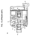
- FIG. 13 shows the structure of such swash plate type compressor.
- pressure in the crank chamber 51 (crank chamber pressure Pc) is controlled for changing the inclination angle of the swash plate 1, thereby adjusting the displacement of the compressor 50.
- the front housing 55 of the compressor 50 has a passage 56 formed therein.
- a drive shaft 58 has a communication passage 59 formed therein.
- the crank chamber 51 is sealed by a lip seal 57 which is provided between the front housing 55 and the outer peripheral surface of the drive shaft 58.
- part of refrigerant in the discharge chamber 54 is introduced into the crank chamber 51 with its flow rate being adjusted by the control valve 53.
- Refrigerant introduced into the crank chamber 51 is used to create the crank chamber pressure Pc and then flows through the passage 56 in the front housing 55, the communication passage 59 in the drive shaft 58 and other passages formed in the compressor 50 finally into the suction chamber 60, as indicated by arrows.
- the refrigerant contains lubricating oil which is supplied into the crank chamber 51 and then guided through the oil supply passage 63 and the passage 56 to the lip seal 57 together with refrigerant for lubricating the lip seal 57.
- the lubricating oil is finally drawn to the suction chamber 60 through the communication passage 59.
- crank chamber 51 refrigerant introduced into the crank chamber 51 increases in temperature while it flows in the crank chamber 51, which impedes cooling of the heat-generating sliding portions of the compressor 50, such as the lip seal 57, a thrust bearing 61 and a link 62, requiring cooling during operation of the compressor 50.
- the present invention is directed to providing a swash plate type compressor that can sufficiently cool the heat-generating sliding portions of the compressor.
- a swash plate type compressor has a housing, a drive shaft, a lug plate, a swash plate, a piston and a heat-generating sliding portion.
- the housing has a cylinder bore, a suction pressure region, a discharge pressure region and a crank chamber.
- the drive shaft is rotatably supported by the housing.
- the lug plate is secured to the drive shaft.
- the swash plate is tiltably coupled to the lug plate.
- the piston is coupled to the swash plate and reciprocally accommodated in the cylinder bore.
- Refrigerant in the discharge pressure region is introduced into the crank chamber through a supply passage while the refrigerant in the crank chamber is drawn out to the suction pressure region through a bleed passage for controlling pressure in the crank chamber, whereby inclination angle of the swash plate is changed.
- the heat-generating sliding portion is provided in the crank chamber.
- the supply passage includes a communication port that communicates with the crank chamber and a first throttle portion for throttling the refrigerant. At least parts of the supply passage and the bleed passage are formed in the drive shaft. A part of the bleed passage formed in the drive shaft is located between a part of the supply passage formed in the drive shaft and an outer peripheral surface of the drive shaft.
- the compressor 1 includes a cylinder block 2. It is noted that the left side and the right side of the compressor 1 as seen in FIG. 1 correspond to the front side and the rear side of the compressor 1, respectively.
- a front housing 3 is connected to the front end of the cylinder block 2.
- a valve port assembly 4 is connected to the rear end of the cylinder block 2.
- a rear housing 5 is connected to the rear end of the valve port assembly 4. The cylinder block 2 and the front housing 3 cooperate to form a crank chamber 6.
- a drive shaft 7 is rotatably supported by the front housing 3 and the cylinder block 2.
- the drive shaft 7 includes a cylindrical hollow first shaft portion 7a having an opening at one end thereof and a cylindrical hollow second shaft portion 7b having openings at the opposite ends thereof and press-fitted in the opening of the first shaft portion 7a.
- An O-ring 42 is held between the inner peripheral surface of the first shaft portion 7a and the outer peripheral surface of the second shaft portion 7b adjacent to the front end of the second shaft portion 7b.
- the first shaft portion 7a is supported at the front and rear ends thereof by radial bearings 39 and 40, respectively.
- a lug plate 9 is secured to the drive shaft 7 for rotation therewith.
- a thrust bearing 10 is provided between the lug plate 9 and the inner wall surface of the front housing 3.
- a substantially disc-shaped swash plate 11 is tiltably fitted around the drive shaft 7 in the crank chamber 6 and tiltably coupled to the lug plate 9 through a link 12.
- a plurality of pistons 13 is arranged around the drive shaft 7 and coupled to the outer periphery of the swash plate 11 through a pair of shoes 14.
- Each of the pistons 13 is reciprocally accommodated in an associated cylinder bore 16, which is formed in the cylinder block 2. As the swash plate 11 is rotated, the pistons 13 are reciprocated in their associated cylinder bores 16.
- a discharge chamber 17, which is a part of the discharge pressure region of the compressor 1, is formed at the center of the rear housing 5 and connected to an external refrigerant circuit through an outlet (not shown).
- a suction chamber 18, which is a part of the suction pressure region of the compressor 1 is formed around the discharge chamber 17 in the rear housing 5 and connected to the external refrigerant circuit through an inlet (not shown).
- the valve port assembly 4 has suction ports 19, suction valves (not shown), discharge ports 20 and discharge valves (not shown).
- Each of the cylinder bores 16 is communicable with the suction chamber 18 through the respective suction port 19 and with the discharge chamber 17 through the respective discharge port 20.
- a retainer is provided on the rear side of the discharge ports 20.
- a control valve 21 is provided in the rear housing 5 for adjusting the flow rate of refrigerant introduced into the crank chamber 6 thereby to control pressure in the crank chamber (crank chamber pressure Pc).
- the control valve 21 functions as a first throttle portion.
- the control valve 21 is in communication with the discharge chamber 17 through a passage on one hand and with one end of a passage 22 formed in the rear housing 5 on the other.
- the passage 22 extends from the control valve 21 toward the valve port assembly 4 and communicates with one end of a passage 23 formed in the valve port assembly 4.
- the other end of the passage 23 is in communication with one end of a passage 24 formed in the cylinder block 2 and the other end of the passage 24 is in communication with one end of a passage 25 formed axially in the drive shaft 7.
- the other end of the passage 25 is in communication with a passage 26 that communicates with the crank chamber 6.
- the passage 26 has a communication port 26a which is radially opened to the crank chamber 6 and in communication with the lip seal 8.
- the control valve 21 and the passages 22, 23, 24, 25, 26 cooperate to form a supply passage for supplying refrigerant in the discharge pressure region into the crank chamber 6.
- the drive shaft 7 has a passage 35 formed between the swash plate 11 and the lug plate 9 and having a communication port for drawing refrigerant and lubricating oil from the crank chamber 6 toward the suction chamber 18.
- the passage 35 is in communication with one end of a passage 36, the other end of which is in communication with one end of a passage 37 formed in the cylinder block 2. It is noted that a lip seal 38 is provided between the passage 36 and the passage 24.
- the passage 37 is in communication with one end of a passage 28 which is formed in the valve port assembly 4 and the other end of which communicates with the suction chamber 18.
- the passages 35, 36, 37, 28 cooperate to form a bleed passage for drawing refrigerant in the crank chamber 6 into the suction pressure region.
- the lip seal 38 is located at the rear end of the drive shaft 7 for sealing the bleed passage from the supply passage, that is, for sealing the inside of the second shaft portion 7b from the outside thereof.
- the lip seal 38 defines the supply passage in the drive shaft 7 together with the inner peripheral surface of the second shaft portion 7b and also defines the bleed passage in the drive shaft 7 together with the inner peripheral surface of the first shaft portion 7a and the outer peripheral surface of the second shaft portion 7b. It is noted that the supply passage and the bleed passage are so formed that the cross-sectional areas at any portion thereof are larger than that of the throttle of the control valve 21, so that the flow of refrigerant in such passages is not prevented.
- FIG. 2 is an enlarged cross-sectional view of the drive shaft 7 that is taken along the line II-II of FIG. 1, that is, an enlarged view of the portion A of FIG. 1.
- the passage 25 which is a part of the supply passage and the passage 36 which is a part of the bleed passage are formed coaxially in the drive shaft 7 as seen in the transverse cross-section across the axial direction thereof.
- the passage 36 is formed between the passage 25 in the second shaft portion 7b and the outer peripheral surface of the first shaft portion 7a, which is the outer peripheral surface of the drive shaft 7.
- Part of refrigerant in the discharge chamber 17 is introduced into the crank chamber 6 for controlling the inclination angle of the swash plate 11.
- the flow rate of refrigerant introduced into the crank chamber 6 is controlled by adjusting the degree of opening of the control valve 21.
- the valve portion of the control valve 21 throttles or regulates the flow of refrigerant thereby to reduce its pressure and hence its temperature.
- the refrigerant is lowered in pressure by passing through the control valve 21 and its temperature is dropped to approximately 100 degrees C.
- Refrigerant that has thus decreased in temperature passes through the passages 22, 23, 24, 25, 26 in this order and is introduced into the crank chamber 6 through the communication port 26a. Since refrigerant that has decreased in temperature and flows past the communication port 26a directly blows onto the lip seal 8 just after being introduced into the crank chamber 6, the lip seal 8 which generates heat during operation of the compressor 1 is cooled by refrigerant.
- Refrigerant thus introduced into the crank chamber 6 serves to adjust the crank chamber pressure Pc in accordance with the degree of opening of the control valve 21, and the inclination angle of the swash plate 11 is controlled by the pressure difference between the crank pressure C and the pressure in the cylinder bores 16, thus controlling the displacement of the compressor 1. That is, the inclination angle of the swash plate 11 may be changed by adjusting the crank chamber pressure Pc in the crank chamber 6.
- Refrigerant in the crank chamber 6 is drawn out to the suction chamber 18 through the passages 35, 36, 37, 28 in this order.
- lubricating oil contained in refrigerant in the crank chamber 6 is not uniformly distributed, but the oil content is less in the region between the swash plate 11 and the lug plate 9.
- refrigerant containing lubricating oil is compelled away from the drive shaft 7 between the swash plate 11 and the lug plate 9 due to the rotating action and centrifugal force of the swash plate 11.
- refrigerant compelled away from the drive shaft 7 due to the operation of the swash plate 11 or other reasons attaches on the inner wall of the front housing 3 or other parts, and some lubricating oil may adhere thereto.
- more lubricating oil is present in the parts other than between the swash plate 11 and the lug plate 9, namely, near the inner wall surface of the front housing 3 and between the swash plate 11 and the cylinder block 2.
- Refrigerant that flows through the bleed passage, particularly through the passage 35, after cooling the lip seal 8, increases in temperature to a level that is still lower than the temperature of peripheral parts of the drive shaft 7, particularly the outer peripheral portion of the drive shaft 7.
- the refrigerant which is decreased in temperature due to throttling by the valve portion of the control valve 21 when refrigerant is introduced into the crank chamber 6 is directly blown onto the lip seal 8. Therefore, the lip seal 8 which is heated during operation of the compressor 1 is cooled down by the refrigerant.
- This cooling effect is synergistically improved by forming the passages 25, 36 in the drive shaft 7 with the passage 36 provided between the passage 25 in the drive shaft 7 and the outer peripheral surface of the first shaft portion 7a. That is, the passage 36, which is a part of the bleed passage, is formed to surround the passage 25, so that the passage 36 and refrigerant flowing therein prevent the heat on the outer peripheral side of the drive shaft 7 from being conducted to the passage 25. Therefore, the temperature of refrigerant in the passage 25 is kept at a lower level. Thus, refrigerant with lower temperature is directly blown onto the lip seal 8, so that the lip seal 8 is further effectively cooled.
- the bleed passage having a communication port 35 for drawing therethrough refrigerant and lubricating oil from the crank chamber 6 into the suction chamber 18 is provided at a position where the refrigerant contains less lubricating oil, rather than at a position near the lip seal 8 where the refrigerant contains more lubricating oil. Therefore, the amount of lubricating oil discharged out of the compressor 1 is reduced and a relatively large amount of lubricating oil is accumulated in the crank chamber 6, so that the compressor 1 is desirably operated during its off state where substantially no refrigerant is introduced, compressed and discharged, but the swash plate 11 is being rotated. Furthermore, the drive shaft 7 which has two passages in the form of cavities can be made advantageously light in weight.
- the first shaft portion 7a and the second shaft portion 7b are made of metal.
- the second shaft portion 7b is made of heat insulation material such as resin.
- the drive shaft 7 is provided with heat insulation treatment, for example, by coating the first shaft portion 7a and/or the second shaft portion 7b with heat insulation material or by fitting a hollow cylindrical heat insulation member on the inner or outer periphery of at least one of the first and second shaft portions 7a, 7b as a part of the drive shaft 7.
- the second shaft portion 7b whose rigidity may be lower than that of the first shaft portion 7a, may be made of a heat insulation material with a lower rigidity.
- the position where the O-ring 42 is provided is not limited to a position between the inner peripheral surface of the first shaft portion 7a and the outer peripheral surface of the second shaft portion 7b.
- the O-ring 42 may be provided between the front end 7x of the second shaft portion 7b and a step 7y which is formed on the inner peripheral surface of the first shaft portion 7a that is engaged with the front end 7x, as shown in FIG. 3.
- the shape of cross-section of the drive shaft 7 is not limited to that of FIG. 1, but the drive shaft 7 may be designed such that the passage 36 is provided between the passage 25 and the outer peripheral surface of the drive shaft 7 and that the passage 36 and the passage 25 are separated from each other, as exemplified in FIGS. 4 through 6.
- the second shaft portion 7b is fitted to the first shaft portion 7a so that the axis of the second shaft portion 7b is offset from the axis of the first shaft portion 7a.
- a part of the inner peripheral surface of the first shaft portion 7a is in contact with a part of the outer peripheral surface of the second shaft portion 7b.
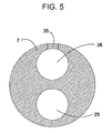
- the drive shaft 7 is formed of a single member having the passage 25 and the passage 36 formed side by side.
- the number of components of the compressor 1 is reduced.
- Each of the passage 25 and the passage 36 of FIG. 5 is circular in cross-section but it may have any other shape than circle such as an elliptical shape, an oblong shape, a shape including a circular arc and a straight line, and a polygonal shape.
- the interior of the first shaft portion 7a is divided by a partition member 7c into two passages 25, 36.
- the partition member 7c has planar surfaces on the both sides, each constituting a part of the respective passages 25, 36.
- the planar surface may be replaced by a curved surface.
- the drive shaft 7 may be constructed simple by using the partition member 7c having a simple shape instead of the cylindrical second shaft portion 7b.
- the passage 36 is provided between the passage 25 and the outer peripheral surface of the first shaft portion 7a.
- the position of the passage 35 in the drive shaft 7 is not limited to that between the swash plate 11 and the lug plate 9, but the passage 35 may be located closer to the lip seal 8 or near the front end of the crank chamber 6, that is, near the position where the drive shaft 7 contacts with the lug plate 9.
- the passage 36 becomes longer and, accordingly, the second shaft portion 7b is formed longer.
- the portion of the passage 25 where refrigerant flowing therein is thermally insulated by the passage 36 becomes longer, so that the heat on the outer peripheral side of the drive shaft 7 is effectively insulated and the lip seal 8 is further effectively cooled.
- the target component of the compressor 1 to be cooled by refrigerant is the lip seal 8 in this embodiment of FIG. 1, but it is not limited to the lip seal 8. If the communication port 26a of the supply passage to the crank chamber 6 is located near the target component for cooling, other heat generating components such as the radial bearing 39, the thrust bearing 10 and the link 12.
- the O-ring 42 which is held between the inner peripheral surface of the first shaft portion 7a and the outer peripheral surface of the second shaft portion 7b near the front end of the second shaft portion 7b may be omitted. That is, the inner peripheral surface of the first shaft portion 7a closely contacts with the outer peripheral surface of the second shaft portion 7b by press-fitting, thereby having a seal structure.
- the second preferred embodiment differs from the first preferred embodiment in that an additional second throttle portion is provided in the supply passage between the control valve 21 as a first throttle portion and the communication port 26a.
- the drive shaft 7' including the first shaft portion 7'a and the second shaft portion 7'b are modified as shown in FIG. 7.
- Those parts and elements of the compressor 1' which are not shown in FIG. 7 are the same as the counterparts of the first preferred embodiment.
- the second shaft portion 7'b has at the front end thereof a second throttle portion 7'h formed integrally therewith.
- the passage 25' includes a first passage part 25'a defined by the inner peripheral surface of the first shaft portion 7'a and a second passage part 25'b defined by the inner peripheral surface of the second shaft portion 7'b.
- the second passage part 25'b has the second throttle portion 7'h formed by reducing the inside diameter of the front end portion of the second shaft portion 7'b.
- Refrigerant passing through the passages 22, 23, 24 in FIG. 1 and the second passage part 25'b of the passage 25' in FIG. 7 is heated by cooling the surroundings.
- the second throttle portion 7'h functions to decompress the heated refrigerant thereby to reduce its temperature.
- the compressor 1 of the second preferred embodiment having the second throttle portion 7'h in the supply passage between the control valve 21 and the communication port 26a, the temperature of refrigerant that reaches the communication port 26a is reduced by the second throttle portion 7'h, with the result that the lip seal 8 is effectively cooled.
- the position where the second throttle portion 7'h is provided is not limited to the front end of the second shaft portion 7'b, but the second throttle portion may be formed as a part of the supply passage in the drive shaft 7 in an alternative embodiment to the second preferred embodiment.
- the second throttle portion may be provided at the rear end or halfway of the second passage part 25'b.
- it may be provided at the front end, rear end or halfway of the first passage part 25'a.
- the distance of the path between the second throttle portion and the lip seal 8 is shortened.
- refrigerant cooled at the second throttle portion is prevented from being heated, so that the lip seal 8 is further efficiently cooled.
- the second throttle portion may be formed separately from the second shaft portion 7'b unlike the one 7'h which is formed integrally with the second shaft portion 7'b as shown in FIG. 7.
- the second throttle portion may be formed integrally with the first shaft portion 7'a or may be formed separately therefrom. Providing the second throttle portion separately from the first or second shaft portions 7'a or 7'b, these shaft portions 7'a, 7'b may be made simple and hence easy to manufacture.
- the third preferred embodiment differs from the first preferred embodiment in that the structure around the rear end of the drive shaft 7 is modified as shown in FIG. 8.
- the first shaft portion 7a is supported by a first bearing 139 or a plain bearing
- the second shaft portion 7b is supported by a second bearing 140 which is also a plain bearing.
- the lip seal 38 of the first preferred embodiment is not provided. Instead, the second bearing 140 is provided for sealing the passage 24 which is a part of the supply passage, from the passage 36 which is a part of the bleed passage. It is noted that the pressure differential between the supply passage and the bleed passage is small enough for the plain bearing 140 to seal the supply passage from the bleed passage.
- the lip seal 38 is replaced by the plain bearing 140 having a higher durability, with the result that durability of the compressor 101 is improved.
- the fourth preferred embodiment differs from the first preferred embodiment in that the structure around the rear end of the drive shaft 7 is modified into a drive shaft 207 as shown in FIG. 9. Though not shown in FIG. 9, the general structure of the drive shaft 207 is substantially the same as the drive shaft 7 of FIG. 1.
- the first shaft portion 207a is supported by a first bearing 239 or a plain bearing.
- An O-ring 241 is provided for sealing the supply passage from the bleed passage.
- the first shaft portion 207a has at its rear end a small diameter portion 207d whose inner diameter is reduced.
- the small diameter portion 207d is fitted around a second shaft portion 207b.
- the first shaft portion 207a has a communication hole 207c that connects a passage 236 to a passage 237.
- a communication groove 237a is formed in the passage 237 adjacent to the communication hole 207c, surrounding the first shaft portion 207a so that the communication groove 237a is in constant communication with the passage 236 irrespective of the position of the communication hole 207c.
- the strength of the drive shaft 207 is improved.
- An O-ring may be provided at a position where the small diameter portion 207d of the first shaft portion 207a is fitted around the second shaft portion 207b for ensuring the seal between the supply passage and the bleed passage.
- the following will describe a fifth preferred embodiment of a swash plate type compressor 301 according to the present invention with reference to FIG. 10.
- the fifth preferred embodiment differs from the first preferred embodiment in that the structure of or around the drive shaft 7 is modified as shown in FIG. 10.
- the general structure of the drive shaft 307 is substantially the same as the drive shaft 7 of FIG. 1.
- the drive shaft 307 includes a first shaft portion 307a and a second shaft portion 307b.
- the first shaft portion 307a has a small diameter portion 307f whose inner diameter is small and a large diameter portion 307g that has an inside diameter larger than the small diameter portion 307f.
- the second shaft portion 307b is press-fitted into the large diameter portion 307g of the first shaft portion 307a.
- FIG. 11 showing a perspective view of the second shaft portion 307b, it has a hollow cylinder and a flange 307d formed at the opposite ends of the cylinder and extending radially outside.
- the hollow portion provides a passage 325 in the compressor 301 which communicates with the passage 24.
- the flange 307d has an outside diameter that is substantially equal to the inside diameter of the large diameter portion 307g of the first shaft portion 307a, so that the passage 325 is so sealed with the flange 307d fitted in the large diameter portion 307g.
- the flange 307d on the front side of the second shaft portion 307b is engaged with a step 307e formed on the inner peripheral surface of the first shaft portion 307a.
- the inner peripheral surface of the first shaft portion 307a and the flange 307d cooperate to form a seal portion 307y.
- a passage 335 is formed in the first shaft portion 307a at a position between the swash plate 11 and the lug plate 9 for drawing refrigerant from the crank chamber 9 into the suction chamber 18.
- the passage 335 is in communication with one end of a passage 336 which is formed between the inner peripheral surface of the large diameter portion 307g of the first shaft portion 307a and the outer peripheral surface of the second shaft portion 307b.
- the other end of the passage 336 is in communication with one end of a passage 337.
- the first shaft portion 307a has a communication hole 307c that connects the passage 336 to the passage 337.
- a lip seal 338 is provided around the first shaft portion 307a at the rear end thereof for sealing the supply passage from the bleed passage.
- the following will describe a sixth preferred embodiment of a swash plate type compressor 401 according to the present invention with reference to FIG. 12.
- the sixth preferred embodiment differs from the fourth preferred embodiment in that the structure of or around the drive shaft 207 is modified as shown in FIG. 12.
- the general structure of the drive shaft 407 is substantially the same as the drive shaft 7 of FIG. 1.
- the rear end of the first shaft portion 407a of the drive shaft 407 is supported by a plain bearing 439.
- the first shaft portion 407a has at its rear end a small diameter portion 407d whose inner diameter is smaller.
- the small diameter portion 407d of the first shaft portion 407a is fitted around the second shaft portion 407b, thereby sealing a passage 436 in the drive shaft 407 from the passages 24, 425.
- the first shaft portion 407a has a communication hole 407c that connects the passage 436 to the outside of the first shaft portion 407a.
- the plain bearing 439 is provided in contact with the terminal end of the passage 436, that is, over the communication hole 407c through which the passage 436 is in communication with the outside of the first shaft portion 407a.
- the plain bearing 439 has an inner annular groove 439a and an outer annular groove 439b on the inner peripheral surface and the outer peripheral surface thereof, respectively.
- the inner annular groove 439a and the outer annular groove 439b are located, for example, at the axial center of the plain bearing 439.
- Each of the inner annular groove 439a and the outer annular groove 439b has tapered surfaces 439d on its front and rear ends, respectively.
- the inner annular groove 439a is in communication with the outer annular groove 439b through a bearing communication hole 439c that extends through the plain bearing 439.
- the plain bearing 439 is fixed to the cylinder block 402, so that relative position between the communication hole 407c and the bearing communication hole 439c varies with rotation of the drive shaft 407, but the inner annular groove 439a is maintained in constant communication with the communication hole 407c and the passage 437, irrespective of the position of the bearing communication hole 439c. Therefore, the passage 436 is constantly in communication with the passage 437.
- the passage 35 (shown in FIG. 1), the passage 436, the communication hole 407c, the inner annular groove 439a, the bearing communication hole 439c, the outer annular groove 439b, the passage 437 and the passage 28 in FIG. 12 cooperate to form the bleed passage for drawing therethrough refrigerant in the crank chamber 6 into the suction pressure region.
- the plain bearing 439 which is provided at the rear end of the drive shaft 407 functions not only as a support for the drive shaft 407 but also as a seal for the supply passage and the bleed passage, there is no need for providing an additional member such as partition wall for sealing the supply passage from the bleed passage and, therefore, the structure of the compressor becomes simple.
- the bleed passage is not formed outside or at the end of the plain bearing 439 supporting the drive shaft 407, but formed inside thereof (or halfway the plain bearing 439 as seen in the axial direction thereof). Therefore, lubricating oil contained in refrigerant that flows through the bleed passage flows through the entire plain bearing 439, thereby further efficiently lubricating the plain bearing 439.
- the inner annular groove 439a, the outer annular groove 439b and the bearing communication hole 439c are provided at the axial center of the plain bearing 439. It is noted, however, that the position of the inner and outer annular grooves 439a, 439b may be changed to halfway the plain bearing 439 as viewed in its axial direction. The position may be changed so as to achieve efficient sealing effect, for example, in view of the above pressure differential.
- the inner annular groove 439a may be formed not on the inner peripheral surface of the plain bearing 439 but on the outer peripheral surface of the first shaft portion 407a.
- the annular groove 439b does not have to be formed necessarily on the outer peripheral surface of the plain bearing 439, but it may be formed in the inner peripheral surface of the cylinder block 402.
- a swash plate type compressor refrigerant in a discharge pressure region is introduced into a crank chamber through a supply passage while the refrigerant in the crank chamber is drawn out to a suction pressure region through a bleed passage for controlling pressure in the crank chamber, whereby inclination angle of a swash plate is changed.
- a heat-generating sliding portion is provided in the crank chamber.
- the supply passage includes a communication port that communicates with the crank chamber and a first throttle portion for throttling the refrigerant. At least parts of the supply passage and the bleed passage are formed in a drive shaft. A part of the bleed passage formed in the drive shaft is located between a part of the supply passage formed in the drive shaft and an outer peripheral surface of the drive shaft.
Landscapes
- Engineering & Computer Science (AREA)
- Mechanical Engineering (AREA)
- General Engineering & Computer Science (AREA)
- Life Sciences & Earth Sciences (AREA)
- Chemical & Material Sciences (AREA)
- Food Science & Technology (AREA)
- Chemical Kinetics & Catalysis (AREA)
- General Chemical & Material Sciences (AREA)
- Wood Science & Technology (AREA)
- Zoology (AREA)
- Polymers & Plastics (AREA)
- Compressors, Vaccum Pumps And Other Relevant Systems (AREA)
- Compressor (AREA)
Abstract
Description
- The present invention relates to a swash plate type compressor and more particularly to a structure for cooling heat-generating sliding portions of the swash plate type compressor.
- A conventional swash plate type compressor is disclosed, for example, in the unexamined Japanese patent application publication No. 8-284816. FIG. 13 shows the structure of such swash plate type compressor. In the swash
plate type compressor 50 of FIG. 13, pressure in the crank chamber 51 (crank chamber pressure Pc) is controlled for changing the inclination angle of theswash plate 1, thereby adjusting the displacement of thecompressor 50. - The
front housing 55 of thecompressor 50 has a passage 56 formed therein. Adrive shaft 58 has acommunication passage 59 formed therein. Thecrank chamber 51 is sealed by alip seal 57 which is provided between thefront housing 55 and the outer peripheral surface of thedrive shaft 58. - To control the crank chamber pressure Pc, part of refrigerant in the
discharge chamber 54 is introduced into thecrank chamber 51 with its flow rate being adjusted by thecontrol valve 53. Refrigerant introduced into thecrank chamber 51 is used to create the crank chamber pressure Pc and then flows through the passage 56 in thefront housing 55, thecommunication passage 59 in thedrive shaft 58 and other passages formed in thecompressor 50 finally into thesuction chamber 60, as indicated by arrows. - The refrigerant contains lubricating oil which is supplied into the
crank chamber 51 and then guided through theoil supply passage 63 and the passage 56 to thelip seal 57 together with refrigerant for lubricating thelip seal 57. The lubricating oil is finally drawn to thesuction chamber 60 through thecommunication passage 59. - However, refrigerant introduced into the
crank chamber 51 increases in temperature while it flows in thecrank chamber 51, which impedes cooling of the heat-generating sliding portions of thecompressor 50, such as thelip seal 57, a thrust bearing 61 and alink 62, requiring cooling during operation of thecompressor 50. - The present invention is directed to providing a swash plate type compressor that can sufficiently cool the heat-generating sliding portions of the compressor.
- In accordance with the present invention, a swash plate type compressor has a housing, a drive shaft, a lug plate, a swash plate, a piston and a heat-generating sliding portion. The housing has a cylinder bore, a suction pressure region, a discharge pressure region and a crank chamber. The drive shaft is rotatably supported by the housing. The lug plate is secured to the drive shaft. The swash plate is tiltably coupled to the lug plate. The piston is coupled to the swash plate and reciprocally accommodated in the cylinder bore. Refrigerant in the discharge pressure region is introduced into the crank chamber through a supply passage while the refrigerant in the crank chamber is drawn out to the suction pressure region through a bleed passage for controlling pressure in the crank chamber, whereby inclination angle of the swash plate is changed. The heat-generating sliding portion is provided in the crank chamber. The supply passage includes a communication port that communicates with the crank chamber and a first throttle portion for throttling the refrigerant. At least parts of the supply passage and the bleed passage are formed in the drive shaft. A part of the bleed passage formed in the drive shaft is located between a part of the supply passage formed in the drive shaft and an outer peripheral surface of the drive shaft.
- Other aspects and advantages of the invention will become apparent from the following description, taken in conjunction with the accompanying drawings, illustrating by way of example the principles of the invention.
- The features of the present invention that are believed to be novel are set forth with particularity in the appended claims. The invention together with objects and advantages thereof, may best be understood by reference to the following description of the presently preferred embodiments together with the accompanying drawings in which:
- FIG. 1 is a cross-sectional view of a swash plate type compressor according to a first preferred embodiment of the present invention;
- FIG. 2 is a cross-sectional view of a drive shaft of the swash plate type compressor according to the first preferred embodiment of the present invention;
- FIG. 3 is a cross-sectional view of a drive shaft of the swash plate type compressor according to an alternative embodiment to the first preferred embodiment of the present invention;
- FIG. 4 is a cross-sectional view of a drive shaft of the swash plate type compressor according to an alternative embodiment to the first preferred embodiment of the present invention;
- FIG. 5 is a cross-sectional view of a drive shaft of the swash plate type compressor according to an alternative embodiment to the first preferred embodiment of the present invention;
- FIG. 6 is a cross-sectional view of a drive shaft of the swash plate type compressor according to an alternative embodiment to the first preferred embodiment of the present invention;
- FIG. 7 is a partially cross-sectional view of a swash plate type compressor according to a second preferred embodiment of the present invention;
- FIG. 8 is a partially cross-sectional view of a swash plate type compressor according to a third preferred embodiment of the present invention;
- FIG. 9 is a partially cross-sectional view of a swash plate type compressor according to a fourth preferred embodiment of the present invention;
- FIG. 10 is a partially cross-sectional view of a swash plate type compressor according to a fifth preferred embodiment of the present invention;
- FIG. 11 is a perspective view of a second shaft of the swash plate type compressor according to the fifth preferred embodiment of the present invention;
- FIG. 12 is a partially cross-sectional view of a swash plate type compressor according to a sixth preferred embodiment of the present invention; and
- FIG. 13 is a cross-sectional view of a swash plate type compressor according to a prior art.
- The following will describe a first preferred embodiment of a swash
plate type compressor 1 with reference to FIGS. 1 through 6. - Referring to FIG. 1, the
compressor 1 includes acylinder block 2. It is noted that the left side and the right side of thecompressor 1 as seen in FIG. 1 correspond to the front side and the rear side of thecompressor 1, respectively. Afront housing 3 is connected to the front end of thecylinder block 2. Avalve port assembly 4 is connected to the rear end of thecylinder block 2. Furthermore, arear housing 5 is connected to the rear end of thevalve port assembly 4. Thecylinder block 2 and thefront housing 3 cooperate to form a crank chamber 6. - In the crank chamber 6, a
drive shaft 7 is rotatably supported by thefront housing 3 and thecylinder block 2. Thedrive shaft 7 includes a cylindrical hollowfirst shaft portion 7a having an opening at one end thereof and a cylindrical hollowsecond shaft portion 7b having openings at the opposite ends thereof and press-fitted in the opening of thefirst shaft portion 7a. An O-ring 42 is held between the inner peripheral surface of thefirst shaft portion 7a and the outer peripheral surface of thesecond shaft portion 7b adjacent to the front end of thesecond shaft portion 7b. Thefirst shaft portion 7a is supported at the front and rear ends thereof byradial bearings - A
lip seal 8, which is one of the heat-generating sliding portions of thecompressor 1, is provided between the outer peripheral surface of the front end portion of thedrive shaft 7 and thefront housing 3 for sealing of the crank chamber 6. In the crank chamber 6, a lug plate 9 is secured to thedrive shaft 7 for rotation therewith. A thrust bearing 10 is provided between the lug plate 9 and the inner wall surface of thefront housing 3. - A substantially disc-shaped swash plate 11 is tiltably fitted around the
drive shaft 7 in the crank chamber 6 and tiltably coupled to the lug plate 9 through alink 12. A plurality ofpistons 13 is arranged around thedrive shaft 7 and coupled to the outer periphery of the swash plate 11 through a pair ofshoes 14. Each of thepistons 13 is reciprocally accommodated in an associatedcylinder bore 16, which is formed in thecylinder block 2. As the swash plate 11 is rotated, thepistons 13 are reciprocated in their associatedcylinder bores 16. - A
discharge chamber 17, which is a part of the discharge pressure region of thecompressor 1, is formed at the center of therear housing 5 and connected to an external refrigerant circuit through an outlet (not shown). On the other hand, asuction chamber 18, which is a part of the suction pressure region of thecompressor 1, is formed around thedischarge chamber 17 in therear housing 5 and connected to the external refrigerant circuit through an inlet (not shown). - The
valve port assembly 4 hassuction ports 19, suction valves (not shown),discharge ports 20 and discharge valves (not shown). Each of the cylinder bores 16 is communicable with thesuction chamber 18 through therespective suction port 19 and with thedischarge chamber 17 through therespective discharge port 20. A retainer is provided on the rear side of thedischarge ports 20. - A
control valve 21 is provided in therear housing 5 for adjusting the flow rate of refrigerant introduced into the crank chamber 6 thereby to control pressure in the crank chamber (crank chamber pressure Pc). Thecontrol valve 21 functions as a first throttle portion. Thecontrol valve 21 is in communication with thedischarge chamber 17 through a passage on one hand and with one end of apassage 22 formed in therear housing 5 on the other. Thepassage 22 extends from thecontrol valve 21 toward thevalve port assembly 4 and communicates with one end of apassage 23 formed in thevalve port assembly 4. The other end of thepassage 23 is in communication with one end of apassage 24 formed in thecylinder block 2 and the other end of thepassage 24 is in communication with one end of apassage 25 formed axially in thedrive shaft 7. The other end of thepassage 25 is in communication with apassage 26 that communicates with the crank chamber 6. Thepassage 26 has a communication port 26a which is radially opened to the crank chamber 6 and in communication with thelip seal 8. Thecontrol valve 21 and thepassages - The
drive shaft 7 has apassage 35 formed between the swash plate 11 and the lug plate 9 and having a communication port for drawing refrigerant and lubricating oil from the crank chamber 6 toward thesuction chamber 18. Thepassage 35 is in communication with one end of apassage 36, the other end of which is in communication with one end of apassage 37 formed in thecylinder block 2. It is noted that alip seal 38 is provided between thepassage 36 and thepassage 24. Thepassage 37 is in communication with one end of apassage 28 which is formed in thevalve port assembly 4 and the other end of which communicates with thesuction chamber 18. Thepassages lip seal 38 is located at the rear end of thedrive shaft 7 for sealing the bleed passage from the supply passage, that is, for sealing the inside of thesecond shaft portion 7b from the outside thereof. Thelip seal 38 defines the supply passage in thedrive shaft 7 together with the inner peripheral surface of thesecond shaft portion 7b and also defines the bleed passage in thedrive shaft 7 together with the inner peripheral surface of thefirst shaft portion 7a and the outer peripheral surface of thesecond shaft portion 7b. It is noted that the supply passage and the bleed passage are so formed that the cross-sectional areas at any portion thereof are larger than that of the throttle of thecontrol valve 21, so that the flow of refrigerant in such passages is not prevented. - FIG. 2 is an enlarged cross-sectional view of the
drive shaft 7 that is taken along the line II-II of FIG. 1, that is, an enlarged view of the portion A of FIG. 1. As shown in FIG. 2, thepassage 25 which is a part of the supply passage and thepassage 36 which is a part of the bleed passage are formed coaxially in thedrive shaft 7 as seen in the transverse cross-section across the axial direction thereof. To be more specific, thepassage 36 is formed between thepassage 25 in thesecond shaft portion 7b and the outer peripheral surface of thefirst shaft portion 7a, which is the outer peripheral surface of thedrive shaft 7. - The following will describe the operation of the
compressor 1 according to the first preferred embodiment. - As the
drive shaft 7 is driven by a drive source (not shown), the swash plate 11 rotates, with the result that each of thepistons 13 reciprocates in the associated cylinder bore 16. Refrigerant in the external refrigerant circuit is introduced into thesuction chamber 18 and then drawn through therespective suction ports 19 into the cylinder bores 16, in which the refrigerant is compressed by thepistons 13. The compressed refrigerant is forced into thedischarge chamber 17 through thedischarge ports 20 and then discharged out thereof into the external refrigerant circuit. - Part of refrigerant in the
discharge chamber 17 is introduced into the crank chamber 6 for controlling the inclination angle of the swash plate 11. The flow rate of refrigerant introduced into the crank chamber 6 is controlled by adjusting the degree of opening of thecontrol valve 21. When refrigerant passes through thecontrol valve 21, the valve portion of thecontrol valve 21 throttles or regulates the flow of refrigerant thereby to reduce its pressure and hence its temperature. For example, refrigerant in the discharge pressure region subjected to a high pressure and has a temperature of about 150 degrees C. The refrigerant is lowered in pressure by passing through thecontrol valve 21 and its temperature is dropped to approximately 100 degrees C. Refrigerant that has thus decreased in temperature passes through thepassages lip seal 8 just after being introduced into the crank chamber 6, thelip seal 8 which generates heat during operation of thecompressor 1 is cooled by refrigerant. - Refrigerant thus introduced into the crank chamber 6 serves to adjust the crank chamber pressure Pc in accordance with the degree of opening of the
control valve 21, and the inclination angle of the swash plate 11 is controlled by the pressure difference between the crank pressure C and the pressure in the cylinder bores 16, thus controlling the displacement of thecompressor 1. That is, the inclination angle of the swash plate 11 may be changed by adjusting the crank chamber pressure Pc in the crank chamber 6. Refrigerant in the crank chamber 6 is drawn out to thesuction chamber 18 through thepassages - It is noted that lubricating oil contained in refrigerant in the crank chamber 6 is not uniformly distributed, but the oil content is less in the region between the swash plate 11 and the lug plate 9. One reason is that refrigerant containing lubricating oil is compelled away from the
drive shaft 7 between the swash plate 11 and the lug plate 9 due to the rotating action and centrifugal force of the swash plate 11. Another reason is that refrigerant compelled away from thedrive shaft 7 due to the operation of the swash plate 11 or other reasons attaches on the inner wall of thefront housing 3 or other parts, and some lubricating oil may adhere thereto. Thus, there is less lubricating oil between the swash plate 11 and the lug plate 9. On the contrary, more lubricating oil is present in the parts other than between the swash plate 11 and the lug plate 9, namely, near the inner wall surface of thefront housing 3 and between the swash plate 11 and thecylinder block 2. - Refrigerant that flows through the bleed passage, particularly through the
passage 35, after cooling thelip seal 8, increases in temperature to a level that is still lower than the temperature of peripheral parts of thedrive shaft 7, particularly the outer peripheral portion of thedrive shaft 7. - Thus, the refrigerant which is decreased in temperature due to throttling by the valve portion of the
control valve 21 when refrigerant is introduced into the crank chamber 6 is directly blown onto thelip seal 8. Therefore, thelip seal 8 which is heated during operation of thecompressor 1 is cooled down by the refrigerant. - This cooling effect is synergistically improved by forming the
passages drive shaft 7 with thepassage 36 provided between thepassage 25 in thedrive shaft 7 and the outer peripheral surface of thefirst shaft portion 7a. That is, thepassage 36, which is a part of the bleed passage, is formed to surround thepassage 25, so that thepassage 36 and refrigerant flowing therein prevent the heat on the outer peripheral side of thedrive shaft 7 from being conducted to thepassage 25. Therefore, the temperature of refrigerant in thepassage 25 is kept at a lower level. Thus, refrigerant with lower temperature is directly blown onto thelip seal 8, so that thelip seal 8 is further effectively cooled. - Additionally, the bleed passage having a
communication port 35 for drawing therethrough refrigerant and lubricating oil from the crank chamber 6 into thesuction chamber 18 is provided at a position where the refrigerant contains less lubricating oil, rather than at a position near thelip seal 8 where the refrigerant contains more lubricating oil. Therefore, the amount of lubricating oil discharged out of thecompressor 1 is reduced and a relatively large amount of lubricating oil is accumulated in the crank chamber 6, so that thecompressor 1 is desirably operated during its off state where substantially no refrigerant is introduced, compressed and discharged, but the swash plate 11 is being rotated. Furthermore, thedrive shaft 7 which has two passages in the form of cavities can be made advantageously light in weight. - In the first preferred embodiment, the
first shaft portion 7a and thesecond shaft portion 7b are made of metal. In an alternative embodiment, thesecond shaft portion 7b is made of heat insulation material such as resin. In another alternative embodiment, thedrive shaft 7 is provided with heat insulation treatment, for example, by coating thefirst shaft portion 7a and/or thesecond shaft portion 7b with heat insulation material or by fitting a hollow cylindrical heat insulation member on the inner or outer periphery of at least one of the first andsecond shaft portions drive shaft 7. Thesecond shaft portion 7b, whose rigidity may be lower than that of thefirst shaft portion 7a, may be made of a heat insulation material with a lower rigidity. - Thus making part of the
drive shaft 7 using a heat insulation material, the conduction of heat generated on the outer periphery of thedrive shaft 7 to thepassage 25 is prevented more effectively than without using the heat insulation material for thedrive shaft 7. Thus, the cooling of thelip seal 8 is further improved. - The position where the O-
ring 42 is provided is not limited to a position between the inner peripheral surface of thefirst shaft portion 7a and the outer peripheral surface of thesecond shaft portion 7b. For example, the O-ring 42 may be provided between thefront end 7x of thesecond shaft portion 7b and astep 7y which is formed on the inner peripheral surface of thefirst shaft portion 7a that is engaged with thefront end 7x, as shown in FIG. 3. - The shape of cross-section of the
drive shaft 7 is not limited to that of FIG. 1, but thedrive shaft 7 may be designed such that thepassage 36 is provided between thepassage 25 and the outer peripheral surface of thedrive shaft 7 and that thepassage 36 and thepassage 25 are separated from each other, as exemplified in FIGS. 4 through 6. - In FIG. 4, the
second shaft portion 7b is fitted to thefirst shaft portion 7a so that the axis of thesecond shaft portion 7b is offset from the axis of thefirst shaft portion 7a. A part of the inner peripheral surface of thefirst shaft portion 7a is in contact with a part of the outer peripheral surface of thesecond shaft portion 7b. In such arrangement of theshaft portions second shaft portion 7b is easily assembled and supported. - In FIG. 5, the
drive shaft 7 is formed of a single member having thepassage 25 and thepassage 36 formed side by side. Thus, the number of components of thecompressor 1 is reduced. Each of thepassage 25 and thepassage 36 of FIG. 5 is circular in cross-section but it may have any other shape than circle such as an elliptical shape, an oblong shape, a shape including a circular arc and a straight line, and a polygonal shape. - In FIG. 6, the interior of the
first shaft portion 7a is divided by apartition member 7c into twopassages partition member 7c has planar surfaces on the both sides, each constituting a part of therespective passages drive shaft 7 may be constructed simple by using thepartition member 7c having a simple shape instead of the cylindricalsecond shaft portion 7b. In this case, thepassage 36 is provided between thepassage 25 and the outer peripheral surface of thefirst shaft portion 7a. - Furthermore, the position of the
passage 35 in thedrive shaft 7 is not limited to that between the swash plate 11 and the lug plate 9, but thepassage 35 may be located closer to thelip seal 8 or near the front end of the crank chamber 6, that is, near the position where thedrive shaft 7 contacts with the lug plate 9. - In such a case, the
passage 36 becomes longer and, accordingly, thesecond shaft portion 7b is formed longer. Thus, the portion of thepassage 25 where refrigerant flowing therein is thermally insulated by thepassage 36 becomes longer, so that the heat on the outer peripheral side of thedrive shaft 7 is effectively insulated and thelip seal 8 is further effectively cooled. - The target component of the
compressor 1 to be cooled by refrigerant is thelip seal 8 in this embodiment of FIG. 1, but it is not limited to thelip seal 8. If the communication port 26a of the supply passage to the crank chamber 6 is located near the target component for cooling, other heat generating components such as theradial bearing 39, thethrust bearing 10 and thelink 12. - The O-
ring 42 which is held between the inner peripheral surface of thefirst shaft portion 7a and the outer peripheral surface of thesecond shaft portion 7b near the front end of thesecond shaft portion 7b may be omitted. That is, the inner peripheral surface of thefirst shaft portion 7a closely contacts with the outer peripheral surface of thesecond shaft portion 7b by press-fitting, thereby having a seal structure. - The following will describe a second preferred embodiment of a swash plate type compressor 1' according to the present invention with reference to FIG. 7. The second preferred embodiment differs from the first preferred embodiment in that an additional second throttle portion is provided in the supply passage between the
control valve 21 as a first throttle portion and the communication port 26a. For example, the drive shaft 7' including the first shaft portion 7'a and the second shaft portion 7'b are modified as shown in FIG. 7. Those parts and elements of the compressor 1' which are not shown in FIG. 7 are the same as the counterparts of the first preferred embodiment. - As shown in FIG. 7, the second shaft portion 7'b has at the front end thereof a second throttle portion 7'h formed integrally therewith. The passage 25' includes a first passage part 25'a defined by the inner peripheral surface of the first shaft portion 7'a and a second passage part 25'b defined by the inner peripheral surface of the second shaft portion 7'b. The second passage part 25'b has the second throttle portion 7'h formed by reducing the inside diameter of the front end portion of the second shaft portion 7'b.
- Refrigerant passing through the
passages - According to the
compressor 1 of the second preferred embodiment having the second throttle portion 7'h in the supply passage between thecontrol valve 21 and the communication port 26a, the temperature of refrigerant that reaches the communication port 26a is reduced by the second throttle portion 7'h, with the result that thelip seal 8 is effectively cooled. - The position where the second throttle portion 7'h is provided is not limited to the front end of the second shaft portion 7'b, but the second throttle portion may be formed as a part of the supply passage in the
drive shaft 7 in an alternative embodiment to the second preferred embodiment. For example, the second throttle portion may be provided at the rear end or halfway of the second passage part 25'b. Alternatively, it may be provided at the front end, rear end or halfway of the first passage part 25'a. Particularly, providing the second throttle portion near the front end of the first passage part 25'a, that is, near thepassage 26 of FIG. 1, the distance of the path between the second throttle portion and thelip seal 8 is shortened. Thus, refrigerant cooled at the second throttle portion is prevented from being heated, so that thelip seal 8 is further efficiently cooled. - The second throttle portion may be formed separately from the second shaft portion 7'b unlike the one 7'h which is formed integrally with the second shaft portion 7'b as shown in FIG. 7. The second throttle portion may be formed integrally with the first shaft portion 7'a or may be formed separately therefrom. Providing the second throttle portion separately from the first or second shaft portions 7'a or 7'b, these shaft portions 7'a, 7'b may be made simple and hence easy to manufacture.
- The following will describe a third preferred embodiment of a swash
plate type compressor 101 according to the present invention with reference to FIG. 8. - The third preferred embodiment differs from the first preferred embodiment in that the structure around the rear end of the
drive shaft 7 is modified as shown in FIG. 8. Referring to FIG. 8, thefirst shaft portion 7a is supported by afirst bearing 139 or a plain bearing, and thesecond shaft portion 7b is supported by asecond bearing 140 which is also a plain bearing. - In the third preferred embodiment, the
lip seal 38 of the first preferred embodiment is not provided. Instead, thesecond bearing 140 is provided for sealing thepassage 24 which is a part of the supply passage, from thepassage 36 which is a part of the bleed passage. It is noted that the pressure differential between the supply passage and the bleed passage is small enough for theplain bearing 140 to seal the supply passage from the bleed passage. - According to the third preferred embodiment, the
lip seal 38 is replaced by theplain bearing 140 having a higher durability, with the result that durability of thecompressor 101 is improved. - The following will describe a fourth preferred embodiment of a swash
plate type compressor 201 according to the present invention with reference to FIG. 9. The fourth preferred embodiment differs from the first preferred embodiment in that the structure around the rear end of thedrive shaft 7 is modified into adrive shaft 207 as shown in FIG. 9. Though not shown in FIG. 9, the general structure of thedrive shaft 207 is substantially the same as thedrive shaft 7 of FIG. 1. - Referring to FIG. 9, the
first shaft portion 207a is supported by afirst bearing 239 or a plain bearing. An O-ring 241 is provided for sealing the supply passage from the bleed passage. Thefirst shaft portion 207a has at its rear end asmall diameter portion 207d whose inner diameter is reduced. Thesmall diameter portion 207d is fitted around asecond shaft portion 207b. Furthermore, thefirst shaft portion 207a has acommunication hole 207c that connects apassage 236 to apassage 237. A communication groove 237a is formed in thepassage 237 adjacent to thecommunication hole 207c, surrounding thefirst shaft portion 207a so that the communication groove 237a is in constant communication with thepassage 236 irrespective of the position of thecommunication hole 207c. - According to the fourth preferred embodiment wherein the
drive shaft 207 is so formed that thesmall diameter portion 207d of thefirst shaft portion 207a is directly fitted around the rear end of thesecond shaft portion 207b, the strength of thedrive shaft 207 is improved. - An O-ring may be provided at a position where the
small diameter portion 207d of thefirst shaft portion 207a is fitted around thesecond shaft portion 207b for ensuring the seal between the supply passage and the bleed passage. - The following will describe a fifth preferred embodiment of a swash
plate type compressor 301 according to the present invention with reference to FIG. 10. The fifth preferred embodiment differs from the first preferred embodiment in that the structure of or around thedrive shaft 7 is modified as shown in FIG. 10. Though not shown in FIG. 10, the general structure of thedrive shaft 307 is substantially the same as thedrive shaft 7 of FIG. 1. - The
drive shaft 307 includes afirst shaft portion 307a and asecond shaft portion 307b. Thefirst shaft portion 307a has asmall diameter portion 307f whose inner diameter is small and alarge diameter portion 307g that has an inside diameter larger than thesmall diameter portion 307f. Thesecond shaft portion 307b is press-fitted into thelarge diameter portion 307g of thefirst shaft portion 307a. - Referring to FIG. 11 showing a perspective view of the
second shaft portion 307b, it has a hollow cylinder and aflange 307d formed at the opposite ends of the cylinder and extending radially outside. The hollow portion provides apassage 325 in thecompressor 301 which communicates with thepassage 24. Theflange 307d has an outside diameter that is substantially equal to the inside diameter of thelarge diameter portion 307g of thefirst shaft portion 307a, so that thepassage 325 is so sealed with theflange 307d fitted in thelarge diameter portion 307g. Press-fitting thesecond shaft portion 307b into thefirst shaft portion 307a, theflange 307d on the front side of thesecond shaft portion 307b is engaged with astep 307e formed on the inner peripheral surface of thefirst shaft portion 307a. The inner peripheral surface of thefirst shaft portion 307a and theflange 307d cooperate to form aseal portion 307y. - A
passage 335 is formed in thefirst shaft portion 307a at a position between the swash plate 11 and the lug plate 9 for drawing refrigerant from the crank chamber 9 into thesuction chamber 18. Thepassage 335 is in communication with one end of apassage 336 which is formed between the inner peripheral surface of thelarge diameter portion 307g of thefirst shaft portion 307a and the outer peripheral surface of thesecond shaft portion 307b. The other end of thepassage 336 is in communication with one end of apassage 337. Thefirst shaft portion 307a has acommunication hole 307c that connects thepassage 336 to thepassage 337. Alip seal 338 is provided around thefirst shaft portion 307a at the rear end thereof for sealing the supply passage from the bleed passage. - The following will describe a sixth preferred embodiment of a swash
plate type compressor 401 according to the present invention with reference to FIG. 12. The sixth preferred embodiment differs from the fourth preferred embodiment in that the structure of or around thedrive shaft 207 is modified as shown in FIG. 12. Though not shown in FIG. 12, the general structure of thedrive shaft 407 is substantially the same as thedrive shaft 7 of FIG. 1. - Referring to FIG. 12, the rear end of the
first shaft portion 407a of thedrive shaft 407 is supported by aplain bearing 439. Thefirst shaft portion 407a has at its rear end asmall diameter portion 407d whose inner diameter is smaller. Thesmall diameter portion 407d of thefirst shaft portion 407a is fitted around thesecond shaft portion 407b, thereby sealing apassage 436 in thedrive shaft 407 from thepassages first shaft portion 407a has acommunication hole 407c that connects thepassage 436 to the outside of thefirst shaft portion 407a. Theplain bearing 439 is provided in contact with the terminal end of thepassage 436, that is, over thecommunication hole 407c through which thepassage 436 is in communication with the outside of thefirst shaft portion 407a. - The
plain bearing 439 has an innerannular groove 439a and an outerannular groove 439b on the inner peripheral surface and the outer peripheral surface thereof, respectively. The innerannular groove 439a and the outerannular groove 439b are located, for example, at the axial center of theplain bearing 439. Each of the innerannular groove 439a and the outerannular groove 439b has taperedsurfaces 439d on its front and rear ends, respectively. The innerannular groove 439a is in communication with the outerannular groove 439b through abearing communication hole 439c that extends through theplain bearing 439. - The
plain bearing 439 is fixed to thecylinder block 402, so that relative position between thecommunication hole 407c and thebearing communication hole 439c varies with rotation of thedrive shaft 407, but the innerannular groove 439a is maintained in constant communication with thecommunication hole 407c and thepassage 437, irrespective of the position of the bearingcommunication hole 439c. Therefore, thepassage 436 is constantly in communication with thepassage 437. - The passage 35 (shown in FIG. 1), the
passage 436, thecommunication hole 407c, the innerannular groove 439a, the bearingcommunication hole 439c, the outerannular groove 439b, thepassage 437 and thepassage 28 in FIG. 12 cooperate to form the bleed passage for drawing therethrough refrigerant in the crank chamber 6 into the suction pressure region. - The pressure differential between the
passages annular groove 439a, the outerannular groove 439b and thebearing communication hole 439c that are part of the bleed passage is small enough for theplain bearing 439 to seal successfully the supply passage from the bleed passage. - According to the sixth preferred embodiment wherein the
plain bearing 439 which is provided at the rear end of thedrive shaft 407 functions not only as a support for thedrive shaft 407 but also as a seal for the supply passage and the bleed passage, there is no need for providing an additional member such as partition wall for sealing the supply passage from the bleed passage and, therefore, the structure of the compressor becomes simple. At the rear end of thedrive shaft 407, the bleed passage is not formed outside or at the end of theplain bearing 439 supporting thedrive shaft 407, but formed inside thereof (or halfway theplain bearing 439 as seen in the axial direction thereof). Therefore, lubricating oil contained in refrigerant that flows through the bleed passage flows through the entire plain bearing 439, thereby further efficiently lubricating theplain bearing 439. - In the sixth preferred embodiment, the inner
annular groove 439a, the outerannular groove 439b and thebearing communication hole 439c are provided at the axial center of theplain bearing 439. It is noted, however, that the position of the inner and outerannular grooves plain bearing 439 as viewed in its axial direction. The position may be changed so as to achieve efficient sealing effect, for example, in view of the above pressure differential. - Additionally, the inner
annular groove 439a may be formed not on the inner peripheral surface of theplain bearing 439 but on the outer peripheral surface of thefirst shaft portion 407a. Similarly, theannular groove 439b does not have to be formed necessarily on the outer peripheral surface of theplain bearing 439, but it may be formed in the inner peripheral surface of thecylinder block 402. By so providing theannular grooves plain bearing 439 is improved in strength. - Therefore, the present examples and embodiments are to be considered as illustrative and not restrictive, and the invention is not to be limited to the details given herein but may be modified within the scope of the appended claims. In a swash plate type compressor, refrigerant in a discharge pressure region is introduced into a crank chamber through a supply passage while the refrigerant in the crank chamber is drawn out to a suction pressure region through a bleed passage for controlling pressure in the crank chamber, whereby inclination angle of a swash plate is changed. A heat-generating sliding portion is provided in the crank chamber. The supply passage includes a communication port that communicates with the crank chamber and a first throttle portion for throttling the refrigerant. At least parts of the supply passage and the bleed passage are formed in a drive shaft. A part of the bleed passage formed in the drive shaft is located between a part of the supply passage formed in the drive shaft and an outer peripheral surface of the drive shaft.
Claims (16)
- A swash plate type compressor comprising a housing having a cylinder bore, a suction pressure region, a discharge pressure region and a crank chamber, a drive shaft rotatably supported by the housing, a lug plate secured to the drive shaft, a swash plate tiltably coupled to the lug plate, and a piston coupled to the swash plate and reciprocally accommodated in the cylinder bore, wherein refrigerant in the discharge pressure region is introduced into the crank chamber through a supply passage while the refrigerant in the crank chamber is drawn out to the suction pressure region through a bleed passage for controlling pressure in the crank chamber, whereby inclination angle of the swash plate is changed, characterized in that a heat-generating sliding portion is provided in the crank chamber, in that the supply passage includes a communication port that communicates with the crank chamber and a first throttle portion for throttling the refrigerant, in that at least parts of the supply passage and the bleed passage are formed in the drive shaft, and in that a part of the bleed passage formed in the drive shaft is located between a part of the supply passage formed in the drive shaft and an outer peripheral surface of the drive shaft.
- The swash plate type compressor according to claim 1, wherein the bleed passage includes a communication port that communicates with the crank chamber at a position between the lug plate and the swash plate.
- The swash plate type compressor according to any one of claims 1 and 2, wherein at least a part of the drive shaft is made of heat insulation material.
- The swash plate type compressor according to claim 3, wherein the heat insulation material is resin.
- The swash plate type compressor according to any one of claims 1 through 4, wherein the drive shaft includes a cylindrical hollow first shaft portion and a cylindrical hollow second shaft portion fitted in the first shaft portion, wherein the compressor further comprising a seal member provided at an end portion of the second shaft portion, wherein a part of the bleed passage formed in the drive shaft is defined by an inner peripheral surface of the first shaft portion, an outer peripheral surface of the second shaft portion and the seal member, and wherein a part of the supply passage formed in the drive shaft is defined by an inner peripheral surface of the second shaft portion and the seal member.
- The swash plate type compressor according to claim 5, wherein the first shaft portion and the second shaft portion are formed coaxially with each other.
- The swash plate type compressor according to claim 5, wherein the second shaft portion is fitted to the first shaft portion so that an axis of the second shaft portion is offset from an axis of the first shaft portion.
- The swash plate type compressor according to claim 7, wherein a part of the inner peripheral surface of the first shaft portion is in contact with a part of the outer peripheral surface of the second shaft portion.
- The swash plate type compressor according to any one of claims 1 through 4, wherein the drive shaft includes a cylindrical hollow first shaft portion and a cylindrical hollow second shaft portion fitted in the first shaft, wherein the second shaft portion has a flange formed at opposite ends thereof and extending radially outside, wherein an inner peripheral surface of the first shaft portion and the flanges cooperate to form a seal portion, wherein the bleed passage formed in the drive shaft is defined by an inner peripheral surface of the first shaft portion, an outer peripheral surface of the second shaft portion and the seal portion, and wherein the supply passage formed in the drive shaft is defined by an inner peripheral surface of the second shaft portion and the seal portion.
- The swash plate type compressor according to any one of claims 1 through 4, wherein the drive shaft includes a cylindrical hollow first shaft portion and a partition member which divides an interior of the first shaft portion into a part of the supply passage and a part of the bleed passage.
- The swash plate type compressor according to any one of claims 1 through 10, wherein the heat-generating sliding portion is a lip seal provided around the drive shaft for sealing of the crank chamber from an outside of the housing.
- The swash plate type compressor according to any one of claims 1 through 10, wherein the heat-generating sliding portion is a thrust bearing provided between the lug plate and the housing.
- The swash plate type compressor according to any one of claims 1 through 10, wherein the heat-generating sliding portion is a link which tiltably couples the swash plate to the lug plate.
- The swash plate type compressor according to any one of claims 1 through 13, wherein the supply passage further includes a second throttle portion between the first throttle portion and the communication port of the supply passage which communicates with the crank chamber.
- The swash plate type compressor according to any one of claims 1 through 14, characterized in that a bearing is provided in the housing for supporting the drive shaft, the bearing having a communication hole that extends therethrough, and in that the communication hole is a part of the bleed passage.
- The swash plate type compressor according to any one of claims 1 through 4, wherein the drive shaft is formed of a single member having a part of the supply passage and a part of the bleed passage formed side by side.
Applications Claiming Priority (2)
| Application Number | Priority Date | Filing Date | Title |
|---|---|---|---|
| JP2005020290 | 2005-01-27 | ||
| JP2005149679A JP4483699B2 (en) | 2005-01-27 | 2005-05-23 | Swash plate compressor |
Publications (2)
| Publication Number | Publication Date |
|---|---|
| EP1688618A1 true EP1688618A1 (en) | 2006-08-09 |
| EP1688618B1 EP1688618B1 (en) | 2007-05-23 |
Family
ID=36263960
Family Applications (1)
| Application Number | Title | Priority Date | Filing Date |
|---|---|---|---|
| EP06100781A Expired - Lifetime EP1688618B1 (en) | 2005-01-27 | 2006-01-24 | Swash plate type compressor |
Country Status (5)
| Country | Link |
|---|---|
| US (1) | US7699585B2 (en) |
| EP (1) | EP1688618B1 (en) |
| JP (1) | JP4483699B2 (en) |
| KR (1) | KR100743414B1 (en) |
| DE (1) | DE602006000006T2 (en) |
Families Citing this family (5)
| Publication number | Priority date | Publication date | Assignee | Title |
|---|---|---|---|---|
| JP2008144631A (en) * | 2006-12-07 | 2008-06-26 | Toyota Industries Corp | Variable displacement compressor |
| JP5140402B2 (en) * | 2007-12-06 | 2013-02-06 | カルソニックカンセイ株式会社 | Swash plate compressor |
| EP2088318A1 (en) * | 2008-02-05 | 2009-08-12 | Kabushiki Kaisha Toyota Jidoshokki | Swash plate compressor |
| JP2009264365A (en) * | 2008-03-31 | 2009-11-12 | Toyota Industries Corp | Variable displacement compressor |
| JP6136906B2 (en) * | 2013-12-11 | 2017-05-31 | 株式会社豊田自動織機 | Variable capacity swash plate compressor |
Citations (3)
| Publication number | Priority date | Publication date | Assignee | Title |
|---|---|---|---|---|
| JPH08284816A (en) * | 1995-04-10 | 1996-10-29 | Toyota Autom Loom Works Ltd | Swash plate type compressor |
| EP1447562A2 (en) * | 2003-02-04 | 2004-08-18 | Kabushiki Kaisha Toyota Jidoshokki | Compressor with lubrication structure |
| EP1493923A2 (en) * | 2003-07-03 | 2005-01-05 | Kabushiki Kaisha Toyota Jidoshokki | Swash plate compressor |
Family Cites Families (10)
| Publication number | Priority date | Publication date | Assignee | Title |
|---|---|---|---|---|
| US4685866A (en) | 1985-03-20 | 1987-08-11 | Kabushiki Kaisha Toyoda Jidoshokki Seisakusho | Variable displacement wobble plate type compressor with wobble angle control unit |
| JPH04179874A (en) | 1990-11-13 | 1992-06-26 | Matsushita Electric Ind Co Ltd | Swash plate compressor |
| JPH0518355A (en) | 1991-07-15 | 1993-01-26 | Toyota Autom Loom Works Ltd | Variable capacity type compressor |
| JP3254780B2 (en) | 1993-01-14 | 2002-02-12 | 株式会社豊田自動織機 | Clutchless swinging swash plate type variable displacement compressor |
| JP2002188566A (en) | 2000-10-10 | 2002-07-05 | Toyota Industries Corp | Cooling mechanism in compressor |
| ES2618322T3 (en) | 2000-10-31 | 2017-06-21 | Basf Se | Liquid printing inks for gravure printing and / or flexographic printing with hyperbranched polymers as binder |
| JP2004183605A (en) | 2002-12-05 | 2004-07-02 | Sanden Corp | Electric compressor |
| JP3855949B2 (en) | 2003-03-18 | 2006-12-13 | 株式会社豊田自動織機 | Double-head piston compressor |
| JP4025832B2 (en) * | 2003-04-14 | 2007-12-26 | 株式会社豊田自動織機 | Compressor |
| KR100679909B1 (en) * | 2003-09-02 | 2007-02-07 | 가부시키가이샤 도요다 지도숏키 | Swash plate compressor |
-
2005
- 2005-05-23 JP JP2005149679A patent/JP4483699B2/en not_active Expired - Fee Related
-
2006
- 2006-01-24 EP EP06100781A patent/EP1688618B1/en not_active Expired - Lifetime
- 2006-01-24 DE DE602006000006T patent/DE602006000006T2/en not_active Expired - Lifetime
- 2006-01-26 KR KR1020060008199A patent/KR100743414B1/en not_active Expired - Fee Related
- 2006-01-26 US US11/341,047 patent/US7699585B2/en not_active Expired - Fee Related
Patent Citations (3)
| Publication number | Priority date | Publication date | Assignee | Title |
|---|---|---|---|---|
| JPH08284816A (en) * | 1995-04-10 | 1996-10-29 | Toyota Autom Loom Works Ltd | Swash plate type compressor |
| EP1447562A2 (en) * | 2003-02-04 | 2004-08-18 | Kabushiki Kaisha Toyota Jidoshokki | Compressor with lubrication structure |
| EP1493923A2 (en) * | 2003-07-03 | 2005-01-05 | Kabushiki Kaisha Toyota Jidoshokki | Swash plate compressor |
Non-Patent Citations (1)
| Title |
|---|
| PATENT ABSTRACTS OF JAPAN vol. 1997, no. 02 28 February 1997 (1997-02-28) * |
Also Published As
| Publication number | Publication date |
|---|---|
| US7699585B2 (en) | 2010-04-20 |
| KR20060086879A (en) | 2006-08-01 |
| KR100743414B1 (en) | 2007-07-30 |
| JP2006233952A (en) | 2006-09-07 |
| DE602006000006T2 (en) | 2008-02-07 |
| US20060165536A1 (en) | 2006-07-27 |
| DE602006000006D1 (en) | 2007-07-05 |
| JP4483699B2 (en) | 2010-06-16 |
| EP1688618B1 (en) | 2007-05-23 |
Similar Documents
| Publication | Publication Date | Title |
|---|---|---|
| US20080317584A1 (en) | Compressor | |
| KR20030040063A (en) | Swash plate type compressor | |
| US20060245939A1 (en) | Compressor | |
| US20080145239A1 (en) | Variable displacement compressor | |
| EP1688618B1 (en) | Swash plate type compressor | |
| EP2354548B1 (en) | Variable displacement type reciprocating compressor | |
| JP3985507B2 (en) | Swash plate compressor | |
| JP3979380B2 (en) | Thermal insulation structure in a compressor | |
| US8303263B2 (en) | Swash plate type compressor | |
| CN100464071C (en) | Swash plate compressor | |
| JP2004324590A (en) | Piston type compressor | |
| CN100476202C (en) | variable capacity compressor | |
| JP4630801B2 (en) | Compressor | |
| EP2107245A1 (en) | Variable displacement compressor | |
| WO2005111417A1 (en) | Compressor | |
| JP5130187B2 (en) | Reciprocating compressor | |
| KR101107337B1 (en) | Swash plate compressor | |
| JP2007205165A (en) | Variable displacement type clutch-less compressor | |
| JP2008196455A (en) | Swash plate type variable displacement compressor | |
| JP2000303950A (en) | Lubrication mechanism for compressor | |
| CN104948416A (en) | Variable displacement swash plate compressor | |
| JP2006194182A (en) | Reciprocation type fluid machine | |
| KR20100031409A (en) | Swash-plate type compressor | |
| JP2006316766A (en) | Swash plate type compressor | |
| JP2001153037A (en) | Swash plate type compressor |
Legal Events
| Date | Code | Title | Description |
|---|---|---|---|
| PUAI | Public reference made under article 153(3) epc to a published international application that has entered the european phase |
Free format text: ORIGINAL CODE: 0009012 |
|
| 17P | Request for examination filed |
Effective date: 20060124 |
|
| AK | Designated contracting states |
Kind code of ref document: A1 Designated state(s): AT BE BG CH CY CZ DE DK EE ES FI FR GB GR HU IE IS IT LI LT LU LV MC NL PL PT RO SE SI SK TR |
|
| AX | Request for extension of the european patent |
Extension state: AL BA HR MK YU |
|
| GRAP | Despatch of communication of intention to grant a patent |
Free format text: ORIGINAL CODE: EPIDOSNIGR1 |
|
| GRAS | Grant fee paid |
Free format text: ORIGINAL CODE: EPIDOSNIGR3 |
|
| AKX | Designation fees paid |
Designated state(s): DE FR IT |
|
| GRAA | (expected) grant |
Free format text: ORIGINAL CODE: 0009210 |
|
| AK | Designated contracting states |
Kind code of ref document: B1 Designated state(s): DE FR IT |
|
| REF | Corresponds to: |
Ref document number: 602006000006 Country of ref document: DE Date of ref document: 20070705 Kind code of ref document: P |
|
| PLBE | No opposition filed within time limit |
Free format text: ORIGINAL CODE: 0009261 |
|
| STAA | Information on the status of an ep patent application or granted ep patent |
Free format text: STATUS: NO OPPOSITION FILED WITHIN TIME LIMIT |
|
| 26N | No opposition filed |
Effective date: 20080226 |
|
| PGFP | Annual fee paid to national office [announced via postgrant information from national office to epo] |
Ref country code: FR Payment date: 20120202 Year of fee payment: 7 |
|
| PGFP | Annual fee paid to national office [announced via postgrant information from national office to epo] |
Ref country code: DE Payment date: 20120118 Year of fee payment: 7 |
|
| PGFP | Annual fee paid to national office [announced via postgrant information from national office to epo] |
Ref country code: IT Payment date: 20120116 Year of fee payment: 7 |
|
| REG | Reference to a national code |
Ref country code: FR Ref legal event code: ST Effective date: 20130930 |
|
| PG25 | Lapsed in a contracting state [announced via postgrant information from national office to epo] |
Ref country code: DE Free format text: LAPSE BECAUSE OF NON-PAYMENT OF DUE FEES Effective date: 20130801 |
|
| REG | Reference to a national code |
Ref country code: DE Ref legal event code: R119 Ref document number: 602006000006 Country of ref document: DE Effective date: 20130801 |
|
| PG25 | Lapsed in a contracting state [announced via postgrant information from national office to epo] |
Ref country code: FR Free format text: LAPSE BECAUSE OF NON-PAYMENT OF DUE FEES Effective date: 20130131 |
|
| PG25 | Lapsed in a contracting state [announced via postgrant information from national office to epo] |
Ref country code: IT Free format text: LAPSE BECAUSE OF NON-PAYMENT OF DUE FEES Effective date: 20130124 |