EP1688366B1 - Device for enveloping and emptying a package, and assembly of such device and package - Google Patents
Device for enveloping and emptying a package, and assembly of such device and package Download PDFInfo
- Publication number
- EP1688366B1 EP1688366B1 EP20060075260 EP06075260A EP1688366B1 EP 1688366 B1 EP1688366 B1 EP 1688366B1 EP 20060075260 EP20060075260 EP 20060075260 EP 06075260 A EP06075260 A EP 06075260A EP 1688366 B1 EP1688366 B1 EP 1688366B1
- Authority
- EP
- European Patent Office
- Prior art keywords
- enveloping
- package
- enveloping part
- hinge
- supporting face
- Prior art date
- Legal status (The legal status is an assumption and is not a legal conclusion. Google has not performed a legal analysis and makes no representation as to the accuracy of the status listed.)
- Expired - Lifetime
Links
Images

Classifications
-
- B—PERFORMING OPERATIONS; TRANSPORTING
- B65—CONVEYING; PACKING; STORING; HANDLING THIN OR FILAMENTARY MATERIAL
- B65D—CONTAINERS FOR STORAGE OR TRANSPORT OF ARTICLES OR MATERIALS, e.g. BAGS, BARRELS, BOTTLES, BOXES, CANS, CARTONS, CRATES, DRUMS, JARS, TANKS, HOPPERS, FORWARDING CONTAINERS; ACCESSORIES, CLOSURES, OR FITTINGS THEREFOR; PACKAGING ELEMENTS; PACKAGES
- B65D77/00—Packages formed by enclosing articles or materials in preformed containers, e.g. boxes, cartons, sacks or bags
- B65D77/04—Articles or materials enclosed in two or more containers disposed one within another
- B65D77/0413—Articles or materials enclosed in two or more containers disposed one within another the inner and outer containers being rigid or semi-rigid and the outer container being of polygonal cross-section formed by folding or erecting one or more blanks, e.g. carton
-
- B—PERFORMING OPERATIONS; TRANSPORTING
- B65—CONVEYING; PACKING; STORING; HANDLING THIN OR FILAMENTARY MATERIAL
- B65D—CONTAINERS FOR STORAGE OR TRANSPORT OF ARTICLES OR MATERIALS, e.g. BAGS, BARRELS, BOTTLES, BOXES, CANS, CARTONS, CRATES, DRUMS, JARS, TANKS, HOPPERS, FORWARDING CONTAINERS; ACCESSORIES, CLOSURES, OR FITTINGS THEREFOR; PACKAGING ELEMENTS; PACKAGES
- B65D5/00—Rigid or semi-rigid containers of polygonal cross-section, e.g. boxes, cartons or trays, formed by folding or erecting one or more blanks made of paper
- B65D5/20—Rigid or semi-rigid containers of polygonal cross-section, e.g. boxes, cartons or trays, formed by folding or erecting one or more blanks made of paper by folding-up portions connected to a central panel from all sides to form a container body, e.g. of tray-like form
- B65D5/2004—Rigid or semi-rigid containers of polygonal cross-section, e.g. boxes, cartons or trays, formed by folding or erecting one or more blanks made of paper by folding-up portions connected to a central panel from all sides to form a container body, e.g. of tray-like form the container body having hollow side-walls
- B65D5/2009—Rigid or semi-rigid containers of polygonal cross-section, e.g. boxes, cartons or trays, formed by folding or erecting one or more blanks made of paper by folding-up portions connected to a central panel from all sides to form a container body, e.g. of tray-like form the container body having hollow side-walls all formed by folding extensions of the side walls
-
- Y—GENERAL TAGGING OF NEW TECHNOLOGICAL DEVELOPMENTS; GENERAL TAGGING OF CROSS-SECTIONAL TECHNOLOGIES SPANNING OVER SEVERAL SECTIONS OF THE IPC; TECHNICAL SUBJECTS COVERED BY FORMER USPC CROSS-REFERENCE ART COLLECTIONS [XRACs] AND DIGESTS
- Y02—TECHNOLOGIES OR APPLICATIONS FOR MITIGATION OR ADAPTATION AGAINST CLIMATE CHANGE
- Y02W—CLIMATE CHANGE MITIGATION TECHNOLOGIES RELATED TO WASTEWATER TREATMENT OR WASTE MANAGEMENT
- Y02W30/00—Technologies for solid waste management
- Y02W30/50—Reuse, recycling or recovery technologies
- Y02W30/80—Packaging reuse or recycling, e.g. of multilayer packaging
Definitions
- This invention relates to a device for enveloping and metered emptying of a package provided with at least one receiving space, surrounded by flexible material, with a dispense opening to be opened, surrounded by flexible material, as described, for instance, in applicant's older patent application EP-1 391 397 .
- Dutch patent publication NL 1 018 232 discloses a device for enveloping a package, wherein a cover and a box are hingedly connected on a side of the box in parallel with a longitudinal axis of the package.
- the object of the invention is to provide a device which, in principle, is intended for single use, for instance for a consumer or small user only sporadically having use for the viscous material packaged in the assembly, or as a trial package before the reuse system is purchased.
- a device By making use of a device provided with a first enveloping part provided with a substantially flat supporting face for the package and a second enveloping part provided with a covering face, which is hingedly connected with the first enveloping part and, from a position of use in which the covering face is in the same plane as the supporting face, can be folded back to an enveloping position in which the package is included between the first and the second enveloping part, while the first and the second enveloping part are at least partly manufactured from a one-piece strip of a material which can be provided with a line hinge through a deforming operation, the first and the second enveloping part can be held in their enveloping position by means of connecting means, and the first enveloping part carries coupling means for the package.
- a device in a relatively simple and inexpensive manner, which, in the position of use, affords a relatively long surface for optimally and completely emptying the package, as well as the possibility of effectively mixing several viscous components pressed out of the package.
- the assembly In the enveloping position, the assembly can be optimally displayed and provided with information, while the package is put away whilst effectively protected.
- the package can be closed upon partial emptying by folding back the second enveloping part from the position of use to the enveloping position through a proper positioning of the part of the package in which the dispense opening is present, by combined folding.
- connection between the first and the second enveloping part comprises a hinge panel which is part of the one-piece material strip and is connected on one side via a line hinge with the first enveloping part and via a second line hinge with the second enveloping part.
- this embodiment affords the possibility of obtaining a tauter box-shaped design and the first and second enveloping part can be made of relatively stiff and taut design, which is beneficial both to protective envelopment and the emptying and mixing process, which effect can be improved further still if the first and the second enveloping part are strengthened with a strengthening plate. It may then be elected that a first strengthening plate provided on the first enveloping part forms the supporting face and a second strengthening plate provided on the second enveloping part forms the covering face.
- This embodiment is preferred in particular if the supporting face and/or the covering face are to be manufactured from a material in which a line hinge cannot be provided through deforming.
- this embodiment affords possibilities if specific requirements are to be imposed on the supporting face in connection with pressing the viscous material contained in the package out of the package, or on the covering face in connection with the mixing of components pressed out of different compartments of the package.
- a first strengthening plate is provided on the side of the first enveloping part facing away from the supporting face, and a second strengthening plate on the side of the second enveloping part facing away from the covering face.
- This embodiment can also be preferred when contemplating maximal alignment of the supporting face with respect to the covering face. Such alignment can also be achieved, incidentally, if on the hinge panel a strengthening panel is provided, in which case the first and the second strengthening plate as well as the hinge strip preferably have the same thickness.
- first and the second strengthening plate as well as the hinge strip are manufactured from a one-piece continuous strip of a material which can be provided with a line hinge through a deforming operation, while a still further simplification can be realized if first and second enveloping part, hinge panel, strengthening panel and first and second strengthening plate are manufactured from a one-piece strip.
- the package For the package to be emptied efficiently, it should be non-slidably retained with respect to the supporting face. This can evidently be realized by gluing the package, at least stripwise, onto the supporting face or by hooking lugs and holes. In the case of more than one component, it is preferred that mutually tuned amounts of components be expelled from the package. This can be realized by providing compartment spaces remaining equal in cross section and then emptying these along a line perpendicular thereto. To that end, it is known to provide guide edges on opposite sides of the supporting face and a cooperating expulsion element or spatula.
- the supporting face is at least partly bounded by guide edges in the form of hollow tubes, into which, from one end, with a sliding fit, lugs are slidable which are connected with a coupling rib extending between the lugs, to which the package can be attached.
- These hollows tubes can be formed in a simple manner by providing line hinges in the material of the device, which is suitable therefor and already present.
- the invention further relates to an assembly of a device as discussed in the foregoing, and a package provided with at least one receiving space, surrounded by flexible material, with a dispense opening to be opened, surrounded by flexible material, the package being secured to the device by means of coupling means, in such a way that in the enveloping position the part of the package in which the at least one dispense opening is present, together with the second enveloping part, has been folded over and back, with which in a relatively simple and inexpensive manner an effectively executable phased emptying of a package and mixing of the expelled components can be realized with a disposable assembly.
- the supporting face is at least partly bounded by upstanding guide edges and the expulsion element or the spatula is provided with a design that optimizes cooperation with the upstanding guide edges.
- the assembly represented in Fig. 1 comprises a device 1 and a package 2.
- the device 1 is manufactured from a one-piece blank of a material in which a line hinge can be provided by deforming.
- cardboard is an eminently suitable material, although any other suitable material can be used, for instance plastics can be considered. It is noted that for the purpose of elucidating the various aspects of the assembly, the thickness of the material is represented disproportionately large in the drawings.
- the package 2 is manufactured from two plastic film sheets, which have been sealed together stripwise so as to form two elongate compartments 3 and 4 which are filled with a viscous material.
- the elongate compartments 3 and 4 have the same cross section throughout the most part of their length, but at the same end both narrow in the form of a spout.
- the package 2, that is, the compartments, can be opened by cutting away a strip of material, such that the spout-shaped narrowing parts of the compartments 3 and 4 form dispense openings.
- the device 1 comprises a first enveloping part 5, a second enveloping part 6 and, situated between these, a hinge panel 7.
- the first enveloping part 5 is provided with a supporting face 8 ( Fig. 2 ), which is bounded on opposite sides by hollow tubes 9 and 10 and, between these, carries the package 2.
- the tubes 9 and 10 have been formed by providing line hinges in the blank by deforming, for instance scoring, and thereupon flanging and gluing together. In each of the tubes, an arcuate cut is provided, so that upon flanging into the tubular form, an opening 11 is formed in the tube next to a vertical lip 12.
- the package 2 By its end remote from the spout-shaped narrowed parts of the compartments, the package 2 has been secured, for instance by gluing, to an end wall part 13 which, at its respective ends, is provided with lugs 14 which can be inserted into the hollow tubes to thereby arrest the package 2, whilst lying on the supporting face 8, relative to the enveloping part 5.
- the arrangement is then so dimensioned that the narrowed parts of the compartments 3 and 4, when the lugs 14 have been inserted completely, are situated adjacent the beginning of the second enveloping part 6.
- the first enveloping part 5 is connected, in one piece, via a line hinge 16 obtained by deforming, with the hinge panel 7, which in turn is connected via a line hinge 17 with the second enveloping part 6, which has a width equal to that of the first enveloping part 5 and a length such that at least the first enveloping part 5, upon folding back of the second enveloping part 6, can be completely covered by it.
- the second enveloping part 6 can be made of somewhat longer design, to thereby realize a possibility of suspension from, for instance, a display stand.
- the second enveloping part 6 is provided with a lip 18, which lips are situated such that, when the second enveloping part 6 is folded back, they can be inserted into the openings 11, thereby allowing the assembly to be locked in its enveloping position.
- Fig. 2 it is shown how in the enveloping position, when a package 2 has been opened, the dispense openings are closed by folding back, together with the second enveloping part 6, the part of the package in which the dispense openings are present. It will be clear that to that end the dimensioning of the arrangement should be chosen such that the dispensing part of an opened package, in the opened position of use of the assembly, must project (viewed from the supporting face 8) beyond the hinge panel 7 onto covering face 19.
- a modified embodiment of the device is represented.
- a first enveloping part 25 and a second enveloping part 26 are mutually connected directly via a single hinge line 27.
- the first and second enveloping part are slightly bent towards each other adjacent the line hinge, which promotes closure of the open package, but reduces the stable box shape of the package.
- Fig. 4 the assembly is represented in the position of use, employing a device again modified with respect to Fig. 1 .
- a strengthening plate 38 and 39 is arranged, while such a plate is absent at the hinge panel 37.
- This causes a slight local depression in the surface supporting the package 2, but in view of the disposable character of the assembly and the associated slight material thicknesses of the constituent parts of the device, this is hardly, if at all, of influence on the process of emptying the package.
- the strengthening plates referred to can also be arranged for another purpose, for instance to create improved conditions on the covering face for mixing two components pressed out of a package.
- a device is shown of overall double design, again manufactured from a single blank.
- a first enveloping part 45 forming the supporting face is connected, by way of a line hinge pressed into the blank, with a hinge panel 47 which is coupled via a line hinge with a second enveloping part 46 which, at its end opposite the line hinge, has been bent over through 180° and thus forms a strengthening plate 48.
- this strengthening plate 48 is connected with a strengthening hinge panel 49, which is connected via a line hinge with a further strengthening plate 50.
- This further strengthening plate 50 has been bent over at its end through 90° so as to form an end wall 51 which, by folding back, is of double design and after a further bend terminates between the first enveloping part 45 and the strengthening plate 50.
- a package can be secured to the device, for instance by gluing or stapling.
- the first enveloping part 5 is represented in cross section for further elucidating the emptying phase of the package 2.
- Emptying is done here using a spatula 60, which has a width greater than the perpendicular distance between the hollow tubes 9 and 10 and in two corner areas is provided with rectangular recesses, at least recesses whose profile is tailored to the mutually facing sides of the hollow tubes 9 and 10.
- the recesses are so dimensioned as to abut the top of the hollow tubes 9 and 10 if there is a completely emptied package 2 under the spatula 60, as indicated in Fig. 6 , with the as yet unemptied package 2 extending beyond the spatula 60 in the direction of spout-shaped discharge openings.
- the height of the spatula 60 has been chosen such that it can be conveniently gripped and manipulated by hand.
- the hinge panel 7, whether of double design or not, can be formed by a series of immediately adjacent, mutually parallel line hinges.
- the second enveloping part 26 can be designed in the form of an open box, having in the enveloping position an inclined surface extending from the line hinge 27, with lateral vertical wall parts abutting a flat and straight first enveloping part 25.
- Such a profiled second enveloping part 26 can for instance be made of transparent plastic.
- the spatula can also be designed in many other ways. Thus, it can be manufactured from plastic and provided with a beveled pressure edge on one side and a grip on the other side.
Landscapes
- Engineering & Computer Science (AREA)
- Mechanical Engineering (AREA)
- Packages (AREA)
- Package Specialized In Special Use (AREA)
- Basic Packing Technique (AREA)
Abstract
Description
- This invention relates to a device for enveloping and metered emptying of a package provided with at least one receiving space, surrounded by flexible material, with a dispense opening to be opened, surrounded by flexible material, as described, for instance, in applicant's older patent
application EP-1 391 397 . - With the assembly discussed there, the possibility of emptying the package completely in a handy manner has been realized, while at the same time efficiently enabling metered, stepwise emptying with interim storage. The at least one dispense opening is then effectively closed by clamping it between a stationary and a movable part after the partial emptying of the package. In this assembly, use is made of a device intended for frequent reuse, whereby a completely emptied package is each time replaced with a new, full package.
- It is noted that
Dutch patent publication NL 1 018 232 - The object of the invention is to provide a device which, in principle, is intended for single use, for instance for a consumer or small user only sporadically having use for the viscous material packaged in the assembly, or as a trial package before the reuse system is purchased.
- This object can be realized according to the invention by a device according to
claim 1. By making use of a device provided with a first enveloping part provided with a substantially flat supporting face for the package and a second enveloping part provided with a covering face, which is hingedly connected with the first enveloping part and, from a position of use in which the covering face is in the same plane as the supporting face, can be folded back to an enveloping position in which the package is included between the first and the second enveloping part, while the first and the second enveloping part are at least partly manufactured from a one-piece strip of a material which can be provided with a line hinge through a deforming operation, the first and the second enveloping part can be held in their enveloping position by means of connecting means, and the first enveloping part carries coupling means for the package. Through these measures, in a relatively simple and inexpensive manner, a device can be realized which, in the position of use, affords a relatively long surface for optimally and completely emptying the package, as well as the possibility of effectively mixing several viscous components pressed out of the package. In the enveloping position, the assembly can be optimally displayed and provided with information, while the package is put away whilst effectively protected. The package can be closed upon partial emptying by folding back the second enveloping part from the position of use to the enveloping position through a proper positioning of the part of the package in which the dispense opening is present, by combined folding. That after a number of times of folding back and forth, the package's being folded shut by folding it over will diminish in effectiveness is of lesser relevance in view of the disposable character of the assembly. On the other hand, in view of this character, it is of great advantage that the package, by virtue of the system used, can be emptied substantially completely with extreme meticulousness, which means both a possible use of all of the material purchased and a least possible environmental impact. - To fold back the second enveloping part relative to the first enveloping part to realize the enveloping position and to fold shut a partly emptied package, it can simply suffice to provide a single line hinge in the one-piece strip of material, whereby the covering face and/or the supporting face are to be bent to a slight convexity to be able to include between them the package still partly filled. However, in particular for somewhat thicker packages, it is preferred that the connection between the first and the second enveloping part comprises a hinge panel which is part of the one-piece material strip and is connected on one side via a line hinge with the first enveloping part and via a second line hinge with the second enveloping part. Such an embodiment also allows better for the fact that the material during emptying of the package is pressed in the direction of the dispense opening, so that at the dispense opening the full thickness of the package is present virtually all the time.
- Also, this embodiment affords the possibility of obtaining a tauter box-shaped design and the first and second enveloping part can be made of relatively stiff and taut design, which is beneficial both to protective envelopment and the emptying and mixing process, which effect can be improved further still if the first and the second enveloping part are strengthened with a strengthening plate. It may then be elected that a first strengthening plate provided on the first enveloping part forms the supporting face and a second strengthening plate provided on the second enveloping part forms the covering face. This embodiment is preferred in particular if the supporting face and/or the covering face are to be manufactured from a material in which a line hinge cannot be provided through deforming. Also, this embodiment affords possibilities if specific requirements are to be imposed on the supporting face in connection with pressing the viscous material contained in the package out of the package, or on the covering face in connection with the mixing of components pressed out of different compartments of the package.
- If specific requirements are imposed on the exterior of the package, it may be elected that a first strengthening plate is provided on the side of the first enveloping part facing away from the supporting face, and a second strengthening plate on the side of the second enveloping part facing away from the covering face. This embodiment can also be preferred when contemplating maximal alignment of the supporting face with respect to the covering face. Such alignment can also be achieved, incidentally, if on the hinge panel a strengthening panel is provided, in which case the first and the second strengthening plate as well as the hinge strip preferably have the same thickness. This, in turn, can be realized in a simple manner if the first and the second strengthening plate as well as the hinge strip are manufactured from a one-piece continuous strip of a material which can be provided with a line hinge through a deforming operation, while a still further simplification can be realized if first and second enveloping part, hinge panel, strengthening panel and first and second strengthening plate are manufactured from a one-piece strip.
- For the package to be emptied efficiently, it should be non-slidably retained with respect to the supporting face. This can evidently be realized by gluing the package, at least stripwise, onto the supporting face or by hooking lugs and holes. In the case of more than one component, it is preferred that mutually tuned amounts of components be expelled from the package. This can be realized by providing compartment spaces remaining equal in cross section and then emptying these along a line perpendicular thereto. To that end, it is known to provide guide edges on opposite sides of the supporting face and a cooperating expulsion element or spatula. In such a case, retention of the package on the supporting face can be realized in an advantageous manner if the supporting face is at least partly bounded by guide edges in the form of hollow tubes, into which, from one end, with a sliding fit, lugs are slidable which are connected with a coupling rib extending between the lugs, to which the package can be attached. These hollows tubes can be formed in a simple manner by providing line hinges in the material of the device, which is suitable therefor and already present.
- The invention further relates to an assembly of a device as discussed in the foregoing, and a package provided with at least one receiving space, surrounded by flexible material, with a dispense opening to be opened, surrounded by flexible material, the package being secured to the device by means of coupling means, in such a way that in the enveloping position the part of the package in which the at least one dispense opening is present, together with the second enveloping part, has been folded over and back, with which in a relatively simple and inexpensive manner an effectively executable phased emptying of a package and mixing of the expelled components can be realized with a disposable assembly.
- To further facilitate the operations connected with emptying the package and processing the expelled material, that is, without making use of auxiliary materials and tools, it may be provided that in the enveloping position, next to the package, there is an expulsion element, such as a spatula, between the first and the second enveloping part. It is then further preferred that the supporting face is at least partly bounded by upstanding guide edges and the expulsion element or the spatula is provided with a design that optimizes cooperation with the upstanding guide edges.
- Certainly when the package has been opened and needs to be stored temporarily, measures need to have been taken to keep the device in its enveloping position. This is possible in a variety of ways. In view of the disposable character of the assembly, a solution which, while not durable upon frequent use, is simple and inexpensive can be realized if the supporting face is at least partly bounded by upstanding guide edges in which cuts have been provided in which lips connected with the second enveloping part can be inserted for keeping in the enveloping position the second enveloping part partly enveloping and covering the package in that position.
- The device, and the assembly to be formed therewith, according to the invention will presently be further elucidated on the basis of examples represented in the drawings, though exclusively as non-limiting embodiments. In the drawings:
-
Fig. 1 shows in perspective an assembly with an opened device and a package placed therein; -
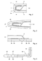
Fig. 2 shows in cross section a part of the assembly according toFig. 1 in the enveloping position; -
Fig. 3 shows a cross section corresponding to that according toFig. 2 , with a second embodiment of the device; -
Fig. 4 shows in cross section a part of an assembly with a third embodiment of the device; -
Fig. 5 shows in cross section a fourth embodiment of the device; and -
Fig. 6 shows in cross section an expulsion element cooperating with the device according toFig. 1 , in the form of a spatula. - The assembly represented in
Fig. 1 comprises adevice 1 and apackage 2. Thedevice 1 is manufactured from a one-piece blank of a material in which a line hinge can be provided by deforming. For such an application, cardboard is an eminently suitable material, although any other suitable material can be used, for instance plastics can be considered. It is noted that for the purpose of elucidating the various aspects of the assembly, the thickness of the material is represented disproportionately large in the drawings. - The
package 2 is manufactured from two plastic film sheets, which have been sealed together stripwise so as to form twoelongate compartments elongate compartments package 2, that is, the compartments, can be opened by cutting away a strip of material, such that the spout-shaped narrowing parts of thecompartments - The
device 1 comprises a firstenveloping part 5, a secondenveloping part 6 and, situated between these, ahinge panel 7. The first envelopingpart 5 is provided with a supporting face 8 (Fig. 2 ), which is bounded on opposite sides byhollow tubes package 2. Thetubes opening 11 is formed in the tube next to avertical lip 12. By its end remote from the spout-shaped narrowed parts of the compartments, thepackage 2 has been secured, for instance by gluing, to anend wall part 13 which, at its respective ends, is provided withlugs 14 which can be inserted into the hollow tubes to thereby arrest thepackage 2, whilst lying on the supportingface 8, relative to theenveloping part 5. The arrangement is then so dimensioned that the narrowed parts of thecompartments lugs 14 have been inserted completely, are situated adjacent the beginning of the secondenveloping part 6. - On the side remote from the
end wall part 13, the firstenveloping part 5 is connected, in one piece, via aline hinge 16 obtained by deforming, with thehinge panel 7, which in turn is connected via aline hinge 17 with the secondenveloping part 6, which has a width equal to that of the first envelopingpart 5 and a length such that at least the first envelopingpart 5, upon folding back of the second envelopingpart 6, can be completely covered by it. If desired, the second envelopingpart 6 can be made of somewhat longer design, to thereby realize a possibility of suspension from, for instance, a display stand. Further, along each of its side edges, the second envelopingpart 6 is provided with alip 18, which lips are situated such that, when the second envelopingpart 6 is folded back, they can be inserted into theopenings 11, thereby allowing the assembly to be locked in its enveloping position. - In
Fig. 2 it is shown how in the enveloping position, when apackage 2 has been opened, the dispense openings are closed by folding back, together with the second envelopingpart 6, the part of the package in which the dispense openings are present. It will be clear that to that end the dimensioning of the arrangement should be chosen such that the dispensing part of an opened package, in the opened position of use of the assembly, must project (viewed from the supporting face 8) beyond thehinge panel 7 onto coveringface 19. - In
Fig. 3 , with respect toFig. 1 andFig. 2 , a modified embodiment of the device is represented. In this modified embodiment, a first envelopingpart 25 and a second envelopingpart 26 are mutually connected directly via asingle hinge line 27. In the enveloping position, the first and second enveloping part are slightly bent towards each other adjacent the line hinge, which promotes closure of the open package, but reduces the stable box shape of the package. - In
Fig. 4 , the assembly is represented in the position of use, employing a device again modified with respect toFig. 1 . In the modified device, on both thefirst enveloping part 35 and thesecond enveloping part 36, a strengtheningplate hinge panel 37. This causes a slight local depression in the surface supporting thepackage 2, but in view of the disposable character of the assembly and the associated slight material thicknesses of the constituent parts of the device, this is hardly, if at all, of influence on the process of emptying the package. Instead of or in addition to a strengthening or stiffening function, the strengthening plates referred to can also be arranged for another purpose, for instance to create improved conditions on the covering face for mixing two components pressed out of a package. - In
Fig. 5 , a device is shown of overall double design, again manufactured from a single blank. Afirst enveloping part 45 forming the supporting face is connected, by way of a line hinge pressed into the blank, with ahinge panel 47 which is coupled via a line hinge with asecond enveloping part 46 which, at its end opposite the line hinge, has been bent over through 180° and thus forms a strengtheningplate 48. Via a line hinge, this strengtheningplate 48 is connected with a strengtheninghinge panel 49, which is connected via a line hinge with a further strengtheningplate 50. This further strengtheningplate 50 has been bent over at its end through 90° so as to form anend wall 51 which, by folding back, is of double design and after a further bend terminates between thefirst enveloping part 45 and the strengtheningplate 50. In this area, a package can be secured to the device, for instance by gluing or stapling. - In
Fig. 6 , thefirst enveloping part 5 is represented in cross section for further elucidating the emptying phase of thepackage 2. Emptying is done here using aspatula 60, which has a width greater than the perpendicular distance between thehollow tubes hollow tubes hollow tubes package 2 under thespatula 60, as indicated inFig. 6 , with the as yetunemptied package 2 extending beyond thespatula 60 in the direction of spout-shaped discharge openings. The height of thespatula 60 has been chosen such that it can be conveniently gripped and manipulated by hand. - It will be clear that within the framework of the invention as laid down in the appended claims, many other modifications and variants are possible. Thus, the
hinge panel 7, whether of double design or not, can be formed by a series of immediately adjacent, mutually parallel line hinges. Further, in the embodiment according toFig. 3 , thesecond enveloping part 26 can be designed in the form of an open box, having in the enveloping position an inclined surface extending from theline hinge 27, with lateral vertical wall parts abutting a flat and straight first envelopingpart 25. Such a profiled second envelopingpart 26 can for instance be made of transparent plastic. The spatula can also be designed in many other ways. Thus, it can be manufactured from plastic and provided with a beveled pressure edge on one side and a grip on the other side.
Claims (15)
- A device (1) for enveloping and metered emptying of a package (2) provided with at least one receiving space, surrounded by flexible material, with a dispense opening to be opened, surrounded by flexible material, which device is provided with a first enveloping part (5; 25) provided with a substantially flat supporting face (8) for the package, an end wall part (13) placed by the end remote from the dispense opening of said package, and a second enveloping part (6; 26) provided with a covering face (19), and, from a position of use in which the covering face is in the same plane as the supporting face, can be folded back to an enveloping position in which the package is included between the first and the second enveloping part, while the first and the second enveloping part are at least partly manufactured from a one-piece strip of a material which can be provided with a line hinge (16) by a deforming operation, the first and the second enveloping part can be held in their enveloping position by means of connecting means, and the first enveloping part carries coupling means for the package,
characterized in that the second enveloping part is hingedly connected with the first enveloping part on the side remote from said end wall part. - A device according to claim 1, wherein the connection between the first and second enveloping part consists of a single line hinge in the one-piece material strip.
- A device according to claim 1, wherein the connection between the first and the second enveloping part comprises a hinge panel (7) which is part of the one-piece material strip and further on one side is connected via a line hinge (16) with the first enveloping part and via a second line hinge (17) with the second enveloping part.
- A device according to claim 3, wherein the first and the second enveloping part are strengthened with a strengthening plate (38; 39).
- A device according to claim 4, wherein a first strengthening plate provided on the first enveloping part forms the supporting face and a second strengthening plate provided on the second enveloping part forms the covering face.
- A device according to claim 4, wherein a first strengthening plate is provided on the side of the first enveloping part facing away from the supporting face, and a second strengthening plate is provided on the side of the second enveloping part facing away from the covering face.
- A device according to claim 5 or 6, wherein a strengthening panel is provided on the hinge panel.
- A device according to claim 7, wherein the first and the second strengthening plate as well as the hinge strip have the same thickness.
- A device according to claim 8, wherein the first and the second strengthening plate as well as the hinge strip are manufactured from a one-piece continuous strip of a material which can be provided with a line hinge by a deforming operation.
- A device according to claim 9, wherein first and second enveloping part, hinge panel, strengthening panel and first and second strengthening plate are manufactured from a one-piece strip.
- A device according to any one of the preceding claims, wherein the supporting face is at least partly bounded by guide edges in the form of hollow tubes (9, 10), into which, from one end, with a sliding fit, lugs (14) are slidable which are connected with a coupling rib extending between the lugs, to which the package can be attached.
- An assembly of a device according to any one of the preceding claims and a package provided with at least one receiving space, surrounded by flexible material, with a dispense opening to be opened, surrounded by flexible material, the package being secured to the device by means of coupling means, such that in the enveloping position the part of the package in which the at least one dispense opening is present, together with the second enveloping part, has been folded over and back.
- An assembly according to claim 12, wherein in the enveloping position, next to the package, there is further an expulsion element, such as a spatula, between the first and the second enveloping part.
- An assembly according to claim 13, wherein the supporting face is at least partly bounded by upstanding guide edges and the expulsion element is provided with a design optimizing cooperation with the upstanding guide edges.
- An assembly according to claim 12, wherein the supporting face is at least partly bounded by upstanding guide edges in which cuts are provided in which lips connected with the second enveloping part can be inserted to keep in the enveloping position the second enveloping part partly enveloping and covering the package in that position.
Applications Claiming Priority (1)
| Application Number | Priority Date | Filing Date | Title |
|---|---|---|---|
| NL1028217A NL1028217C2 (en) | 2005-02-08 | 2005-02-08 | Device for wrapping and emptying a package and assembly of such a device and package. |
Publications (2)
| Publication Number | Publication Date |
|---|---|
| EP1688366A1 EP1688366A1 (en) | 2006-08-09 |
| EP1688366B1 true EP1688366B1 (en) | 2010-05-26 |
Family
ID=34980363
Family Applications (1)
| Application Number | Title | Priority Date | Filing Date |
|---|---|---|---|
| EP20060075260 Expired - Lifetime EP1688366B1 (en) | 2005-02-08 | 2006-02-06 | Device for enveloping and emptying a package, and assembly of such device and package |
Country Status (9)
| Country | Link |
|---|---|
| EP (1) | EP1688366B1 (en) |
| JP (1) | JP2006219201A (en) |
| CN (1) | CN1817754B (en) |
| AT (1) | ATE469054T1 (en) |
| AU (1) | AU2006200522A1 (en) |
| BR (1) | BRPI0600253A (en) |
| CA (1) | CA2535466A1 (en) |
| DE (1) | DE602006014456D1 (en) |
| NL (1) | NL1028217C2 (en) |
Family Cites Families (5)
| Publication number | Priority date | Publication date | Assignee | Title |
|---|---|---|---|---|
| US5480066A (en) * | 1994-07-20 | 1996-01-02 | Blum; Kurt E. | Device for dispensing material from a tube |
| FR2765559B1 (en) * | 1997-07-01 | 1999-09-03 | Oreal | DEVICE FOR THE FRACTIONAL DRAINING OF A TUBE |
| NL1013778C2 (en) * | 1999-12-07 | 2001-06-12 | Intercon Holland B V | Device for dosed emptying of a viscous material-containing packaging. |
| NL1018232C2 (en) * | 2001-06-07 | 2002-12-10 | Intercon Holland B V | Assembly of frame and packing containing viscous material involves packing formed at least partly from foil material provided with first and second opposing outer ends |
| NL1021247C2 (en) * | 2002-08-09 | 2004-02-10 | Intercon Holland B V | Assembly of package and device for dosed emptying of the package and device therefor. |
-
2005
- 2005-02-08 NL NL1028217A patent/NL1028217C2/en not_active IP Right Cessation
-
2006
- 2006-02-06 AT AT06075260T patent/ATE469054T1/en not_active IP Right Cessation
- 2006-02-06 DE DE200660014456 patent/DE602006014456D1/en not_active Expired - Lifetime
- 2006-02-06 EP EP20060075260 patent/EP1688366B1/en not_active Expired - Lifetime
- 2006-02-07 BR BRPI0600253 patent/BRPI0600253A/en not_active IP Right Cessation
- 2006-02-07 CA CA 2535466 patent/CA2535466A1/en not_active Abandoned
- 2006-02-07 AU AU2006200522A patent/AU2006200522A1/en not_active Abandoned
- 2006-02-08 CN CN2006100032807A patent/CN1817754B/en not_active Expired - Fee Related
- 2006-02-08 JP JP2006031125A patent/JP2006219201A/en not_active Withdrawn
Also Published As
| Publication number | Publication date |
|---|---|
| ATE469054T1 (en) | 2010-06-15 |
| BRPI0600253A (en) | 2006-10-03 |
| CN1817754A (en) | 2006-08-16 |
| JP2006219201A (en) | 2006-08-24 |
| EP1688366A1 (en) | 2006-08-09 |
| NL1028217C2 (en) | 2006-08-09 |
| AU2006200522A1 (en) | 2006-08-24 |
| CN1817754B (en) | 2010-08-18 |
| DE602006014456D1 (en) | 2010-07-08 |
| CA2535466A1 (en) | 2006-08-08 |
Similar Documents
| Publication | Publication Date | Title |
|---|---|---|
| US7325718B2 (en) | Portable food dispenser | |
| US8556124B2 (en) | Bag in box packaging having a tap articulating assembly | |
| MXPA04006666A (en) | Corrugated hanging dispenser. | |
| US5429260A (en) | Produce box with plastic walls | |
| US4760938A (en) | Dispenser box and snap open/snap shut closure therefor | |
| EP1688366A1 (en) | Device for enveloping and emptying a package, and assembly of such device and package | |
| KR102280660B1 (en) | Packing Box Assembly for Bundle Packing of Small Packaging Box | |
| CA2456461A1 (en) | Package for toilet seat covers | |
| JP3166545U (en) | Holder for flexible packaging bag | |
| JPS592676Y2 (en) | housing container | |
| JP4128499B2 (en) | Assembly comprising a package and a device for dispensing the package and a device for dispensing the package | |
| US2626095A (en) | Consumer type container | |
| JP2005280824A (en) | Assembly type box | |
| KR200421740Y1 (en) | Goods packaging case | |
| US4222503A (en) | Pouring spout attachment for a container | |
| KR200425308Y1 (en) | Tissue box consisting of trash | |
| JP7712829B2 (en) | Storage box | |
| JPH11152153A (en) | Pouch with spout port | |
| JP3097545U (en) | Packaging box | |
| JP3112518U (en) | Handbag | |
| RU2302985C1 (en) | Consumer's container for carrying of large-sized food products | |
| JP2000190949A (en) | Container | |
| KR200232682Y1 (en) | Product packaging material using waste papers | |
| RU51596U1 (en) | CONSUMER PACKAGING | |
| JPH0554249U (en) | Storage case for web for packaging |
Legal Events
| Date | Code | Title | Description |
|---|---|---|---|
| PUAI | Public reference made under article 153(3) epc to a published international application that has entered the european phase |
Free format text: ORIGINAL CODE: 0009012 |
|
| AK | Designated contracting states |
Kind code of ref document: A1 Designated state(s): AT BE BG CH CY CZ DE DK EE ES FI FR GB GR HU IE IS IT LI LT LU LV MC NL PL PT RO SE SI SK TR |
|
| AX | Request for extension of the european patent |
Extension state: AL BA HR MK YU |
|
| 17P | Request for examination filed |
Effective date: 20070205 |
|
| AKX | Designation fees paid |
Designated state(s): AT BE BG CH CY CZ DE DK EE ES FI FR GB GR HU IE IS IT LI LT LU LV MC NL PL PT RO SE SI SK TR |
|
| 17Q | First examination report despatched |
Effective date: 20070503 |
|
| GRAP | Despatch of communication of intention to grant a patent |
Free format text: ORIGINAL CODE: EPIDOSNIGR1 |
|
| GRAS | Grant fee paid |
Free format text: ORIGINAL CODE: EPIDOSNIGR3 |
|
| GRAA | (expected) grant |
Free format text: ORIGINAL CODE: 0009210 |
|
| AK | Designated contracting states |
Kind code of ref document: B1 Designated state(s): AT BE BG CH CY CZ DE DK EE ES FI FR GB GR HU IE IS IT LI LT LU LV MC NL PL PT RO SE SI SK TR |
|
| REG | Reference to a national code |
Ref country code: GB Ref legal event code: FG4D |
|
| REG | Reference to a national code |
Ref country code: CH Ref legal event code: EP |
|
| REG | Reference to a national code |
Ref country code: IE Ref legal event code: FG4D |
|
| REF | Corresponds to: |
Ref document number: 602006014456 Country of ref document: DE Date of ref document: 20100708 Kind code of ref document: P |
|
| REG | Reference to a national code |
Ref country code: NL Ref legal event code: T3 |
|
| LTIE | Lt: invalidation of european patent or patent extension |
Effective date: 20100526 |
|
| PG25 | Lapsed in a contracting state [announced via postgrant information from national office to epo] |
Ref country code: LT Free format text: LAPSE BECAUSE OF FAILURE TO SUBMIT A TRANSLATION OF THE DESCRIPTION OR TO PAY THE FEE WITHIN THE PRESCRIBED TIME-LIMIT Effective date: 20100526 Ref country code: SE Free format text: LAPSE BECAUSE OF FAILURE TO SUBMIT A TRANSLATION OF THE DESCRIPTION OR TO PAY THE FEE WITHIN THE PRESCRIBED TIME-LIMIT Effective date: 20100526 |
|
| PG25 | Lapsed in a contracting state [announced via postgrant information from national office to epo] |
Ref country code: IS Free format text: LAPSE BECAUSE OF FAILURE TO SUBMIT A TRANSLATION OF THE DESCRIPTION OR TO PAY THE FEE WITHIN THE PRESCRIBED TIME-LIMIT Effective date: 20100926 Ref country code: SI Free format text: LAPSE BECAUSE OF FAILURE TO SUBMIT A TRANSLATION OF THE DESCRIPTION OR TO PAY THE FEE WITHIN THE PRESCRIBED TIME-LIMIT Effective date: 20100526 Ref country code: AT Free format text: LAPSE BECAUSE OF FAILURE TO SUBMIT A TRANSLATION OF THE DESCRIPTION OR TO PAY THE FEE WITHIN THE PRESCRIBED TIME-LIMIT Effective date: 20100526 Ref country code: FI Free format text: LAPSE BECAUSE OF FAILURE TO SUBMIT A TRANSLATION OF THE DESCRIPTION OR TO PAY THE FEE WITHIN THE PRESCRIBED TIME-LIMIT Effective date: 20100526 Ref country code: LV Free format text: LAPSE BECAUSE OF FAILURE TO SUBMIT A TRANSLATION OF THE DESCRIPTION OR TO PAY THE FEE WITHIN THE PRESCRIBED TIME-LIMIT Effective date: 20100526 |
|
| PG25 | Lapsed in a contracting state [announced via postgrant information from national office to epo] |
Ref country code: GR Free format text: LAPSE BECAUSE OF FAILURE TO SUBMIT A TRANSLATION OF THE DESCRIPTION OR TO PAY THE FEE WITHIN THE PRESCRIBED TIME-LIMIT Effective date: 20100827 Ref country code: CY Free format text: LAPSE BECAUSE OF FAILURE TO SUBMIT A TRANSLATION OF THE DESCRIPTION OR TO PAY THE FEE WITHIN THE PRESCRIBED TIME-LIMIT Effective date: 20100526 Ref country code: PL Free format text: LAPSE BECAUSE OF FAILURE TO SUBMIT A TRANSLATION OF THE DESCRIPTION OR TO PAY THE FEE WITHIN THE PRESCRIBED TIME-LIMIT Effective date: 20100526 |
|
| PG25 | Lapsed in a contracting state [announced via postgrant information from national office to epo] |
Ref country code: PT Free format text: LAPSE BECAUSE OF FAILURE TO SUBMIT A TRANSLATION OF THE DESCRIPTION OR TO PAY THE FEE WITHIN THE PRESCRIBED TIME-LIMIT Effective date: 20100927 Ref country code: EE Free format text: LAPSE BECAUSE OF FAILURE TO SUBMIT A TRANSLATION OF THE DESCRIPTION OR TO PAY THE FEE WITHIN THE PRESCRIBED TIME-LIMIT Effective date: 20100526 Ref country code: DK Free format text: LAPSE BECAUSE OF FAILURE TO SUBMIT A TRANSLATION OF THE DESCRIPTION OR TO PAY THE FEE WITHIN THE PRESCRIBED TIME-LIMIT Effective date: 20100526 |
|
| PG25 | Lapsed in a contracting state [announced via postgrant information from national office to epo] |
Ref country code: SK Free format text: LAPSE BECAUSE OF FAILURE TO SUBMIT A TRANSLATION OF THE DESCRIPTION OR TO PAY THE FEE WITHIN THE PRESCRIBED TIME-LIMIT Effective date: 20100526 Ref country code: RO Free format text: LAPSE BECAUSE OF FAILURE TO SUBMIT A TRANSLATION OF THE DESCRIPTION OR TO PAY THE FEE WITHIN THE PRESCRIBED TIME-LIMIT Effective date: 20100526 Ref country code: CZ Free format text: LAPSE BECAUSE OF FAILURE TO SUBMIT A TRANSLATION OF THE DESCRIPTION OR TO PAY THE FEE WITHIN THE PRESCRIBED TIME-LIMIT Effective date: 20100526 Ref country code: BE Free format text: LAPSE BECAUSE OF FAILURE TO SUBMIT A TRANSLATION OF THE DESCRIPTION OR TO PAY THE FEE WITHIN THE PRESCRIBED TIME-LIMIT Effective date: 20100526 |
|
| PG25 | Lapsed in a contracting state [announced via postgrant information from national office to epo] |
Ref country code: IT Free format text: LAPSE BECAUSE OF FAILURE TO SUBMIT A TRANSLATION OF THE DESCRIPTION OR TO PAY THE FEE WITHIN THE PRESCRIBED TIME-LIMIT Effective date: 20100526 |
|
| PLBE | No opposition filed within time limit |
Free format text: ORIGINAL CODE: 0009261 |
|
| STAA | Information on the status of an ep patent application or granted ep patent |
Free format text: STATUS: NO OPPOSITION FILED WITHIN TIME LIMIT |
|
| 26N | No opposition filed |
Effective date: 20110301 |
|
| REG | Reference to a national code |
Ref country code: DE Ref legal event code: R097 Ref document number: 602006014456 Country of ref document: DE Effective date: 20110228 |
|
| PG25 | Lapsed in a contracting state [announced via postgrant information from national office to epo] |
Ref country code: MC Free format text: LAPSE BECAUSE OF NON-PAYMENT OF DUE FEES Effective date: 20110228 |
|
| REG | Reference to a national code |
Ref country code: CH Ref legal event code: PL |
|
| PG25 | Lapsed in a contracting state [announced via postgrant information from national office to epo] |
Ref country code: LI Free format text: LAPSE BECAUSE OF NON-PAYMENT OF DUE FEES Effective date: 20110228 Ref country code: CH Free format text: LAPSE BECAUSE OF NON-PAYMENT OF DUE FEES Effective date: 20110228 |
|
| REG | Reference to a national code |
Ref country code: IE Ref legal event code: MM4A |
|
| PG25 | Lapsed in a contracting state [announced via postgrant information from national office to epo] |
Ref country code: IE Free format text: LAPSE BECAUSE OF NON-PAYMENT OF DUE FEES Effective date: 20110206 |
|
| PGFP | Annual fee paid to national office [announced via postgrant information from national office to epo] |
Ref country code: FR Payment date: 20120227 Year of fee payment: 7 |
|
| PGFP | Annual fee paid to national office [announced via postgrant information from national office to epo] |
Ref country code: DE Payment date: 20120221 Year of fee payment: 7 |
|
| PGFP | Annual fee paid to national office [announced via postgrant information from national office to epo] |
Ref country code: GB Payment date: 20120221 Year of fee payment: 7 |
|
| PGFP | Annual fee paid to national office [announced via postgrant information from national office to epo] |
Ref country code: NL Payment date: 20120227 Year of fee payment: 7 |
|
| PG25 | Lapsed in a contracting state [announced via postgrant information from national office to epo] |
Ref country code: LU Free format text: LAPSE BECAUSE OF NON-PAYMENT OF DUE FEES Effective date: 20110206 |
|
| REG | Reference to a national code |
Ref country code: NL Ref legal event code: V1 Effective date: 20130901 |
|
| PG25 | Lapsed in a contracting state [announced via postgrant information from national office to epo] |
Ref country code: TR Free format text: LAPSE BECAUSE OF FAILURE TO SUBMIT A TRANSLATION OF THE DESCRIPTION OR TO PAY THE FEE WITHIN THE PRESCRIBED TIME-LIMIT Effective date: 20100526 Ref country code: BG Free format text: LAPSE BECAUSE OF FAILURE TO SUBMIT A TRANSLATION OF THE DESCRIPTION OR TO PAY THE FEE WITHIN THE PRESCRIBED TIME-LIMIT Effective date: 20100826 |
|
| GBPC | Gb: european patent ceased through non-payment of renewal fee |
Effective date: 20130206 |
|
| PG25 | Lapsed in a contracting state [announced via postgrant information from national office to epo] |
Ref country code: HU Free format text: LAPSE BECAUSE OF FAILURE TO SUBMIT A TRANSLATION OF THE DESCRIPTION OR TO PAY THE FEE WITHIN THE PRESCRIBED TIME-LIMIT Effective date: 20100526 Ref country code: NL Free format text: LAPSE BECAUSE OF NON-PAYMENT OF DUE FEES Effective date: 20130901 Ref country code: ES Free format text: LAPSE BECAUSE OF FAILURE TO SUBMIT A TRANSLATION OF THE DESCRIPTION OR TO PAY THE FEE WITHIN THE PRESCRIBED TIME-LIMIT Effective date: 20100906 |
|
| REG | Reference to a national code |
Ref country code: FR Ref legal event code: ST Effective date: 20131031 |
|
| REG | Reference to a national code |
Ref country code: DE Ref legal event code: R119 Ref document number: 602006014456 Country of ref document: DE Effective date: 20130903 |
|
| PG25 | Lapsed in a contracting state [announced via postgrant information from national office to epo] |
Ref country code: DE Free format text: LAPSE BECAUSE OF NON-PAYMENT OF DUE FEES Effective date: 20130903 Ref country code: GB Free format text: LAPSE BECAUSE OF NON-PAYMENT OF DUE FEES Effective date: 20130206 Ref country code: FR Free format text: LAPSE BECAUSE OF NON-PAYMENT OF DUE FEES Effective date: 20130228 |