EP1688094A1 - Ultrasonic diagnostic apparatus and method for controlling the same - Google Patents
Ultrasonic diagnostic apparatus and method for controlling the same Download PDFInfo
- Publication number
- EP1688094A1 EP1688094A1 EP05740921A EP05740921A EP1688094A1 EP 1688094 A1 EP1688094 A1 EP 1688094A1 EP 05740921 A EP05740921 A EP 05740921A EP 05740921 A EP05740921 A EP 05740921A EP 1688094 A1 EP1688094 A1 EP 1688094A1
- Authority
- EP
- European Patent Office
- Prior art keywords
- cardiac cycle
- ultrasonic
- partial period
- diagnostic apparatus
- ultrasonic diagnostic
- Prior art date
- Legal status (The legal status is an assumption and is not a legal conclusion. Google has not performed a legal analysis and makes no representation as to the accuracy of the status listed.)
- Withdrawn
Links
Images



Classifications
-
- A—HUMAN NECESSITIES
- A61—MEDICAL OR VETERINARY SCIENCE; HYGIENE
- A61B—DIAGNOSIS; SURGERY; IDENTIFICATION
- A61B8/00—Diagnosis using ultrasonic, sonic or infrasonic waves
- A61B8/08—Clinical applications
- A61B8/0858—Clinical applications involving measuring tissue layers, e.g. skin, interfaces
-
- A—HUMAN NECESSITIES
- A61—MEDICAL OR VETERINARY SCIENCE; HYGIENE
- A61B—DIAGNOSIS; SURGERY; IDENTIFICATION
- A61B5/00—Measuring for diagnostic purposes; Identification of persons
- A61B5/02—Detecting, measuring or recording for evaluating the cardiovascular system, e.g. pulse, heart rate, blood pressure or blood flow
- A61B5/02007—Evaluating blood vessel condition, e.g. elasticity, compliance
-
- A—HUMAN NECESSITIES
- A61—MEDICAL OR VETERINARY SCIENCE; HYGIENE
- A61B—DIAGNOSIS; SURGERY; IDENTIFICATION
- A61B5/00—Measuring for diagnostic purposes; Identification of persons
- A61B5/103—Measuring devices for testing the shape, pattern, colour, size or movement of the body or parts thereof, for diagnostic purposes
- A61B5/107—Measuring physical dimensions, e.g. size of the entire body or parts thereof
- A61B5/1075—Measuring physical dimensions, e.g. size of the entire body or parts thereof for measuring dimensions by non-invasive methods, e.g. for determining thickness of tissue layer
-
- A—HUMAN NECESSITIES
- A61—MEDICAL OR VETERINARY SCIENCE; HYGIENE
- A61B—DIAGNOSIS; SURGERY; IDENTIFICATION
- A61B8/00—Diagnosis using ultrasonic, sonic or infrasonic waves
- A61B8/54—Control of the diagnostic device
- A61B8/543—Control of the diagnostic device involving acquisition triggered by a physiological signal
Definitions
- the present invention relates to an ultrasonic diagnostic apparatus for measuring the elastic property of a vital tissue using an ultrasonic wave and also relates to a method for controlling such an ultrasonic diagnostic apparatus.
- the pathopoiesis of heart or brain infarction is closely correlated to arterial sclerosis. More specifically, if an atheroma is created on the arterial wall or if no arterial cells are produced anymore due to various factors such as elevated blood pressure, then the artery loses its elasticity to become hard and fragile. Also, if the blood vessel is clogged up where the atheroma has been created or if a vascular tissue covering the atheroma has ruptured, then the atheroma will move itself into the blood vessel to clog up the artery elsewhere or to rupture the hardened portions of the artery. As a result, these diseases are caused. That is why it is important to diagnose the arterial sclerosis as early as possible to prevent or treat these diseases.
- the arterial sclerosis can be diagnosed early enough to administer some medicine to its patient, then the disease can be treated effectively. However, it is said that once the arterial sclerosis has advanced to a certain degree, the farther advancement of that disease can be checked with the administration of medicine but it is difficult to repair the hardened artery completely.
- the lesion of arterial sclerosis is diagnosed by directly observing the inside of the blood vessel with a vascular catheter.
- this diagnosis needs to be carried out with a vascular catheter inserted into the blood vessel of a patient, thus imposing a heavy load on him or her.
- the vascular catheter observation is usually adopted to locate the lesion of arterial sclerosis in a patient who is already known to suffer from that disease but has never been used to make a medical checkup on a supposedly healthy person.
- a checkup may be easily made without imposing excessively heavy load on a patient if the index of cholesterol, which is one of major causes of arterial sclerosis, or the blood pressure is measured. However, none of these values directly indicates the degree of advancement of arterial sclerosis.
- An ultrasonic diagnostic apparatus has been used in the prior art as a medical apparatus that imposes only a light load on its patient. Specifically, by irradiating the patient with an ultrasonic wave that has been produced externally by the ultrasonic diagnostic apparatus, geometric information, mobility information or quality information of his or her internal body can be acquired without causing pain to him or her.
- the elastic property of the object can be estimated by the magnitude of positional displacement of the object. That is to say, in this case, the elastic property of the blood vessel of an organism can be evaluated and the degree of advancement of arterial sclerosis can be known directly.
- the measurement can be done just by putting an ultrasonic probe on a patient, and very little load is placed on him or her. For that reason, if the ultrasonic diagnostic apparatus is used, the arterial sclerosis could be diagnosed accurately and a preventive checkup could be carried out on a person under measurement without imposing excessive load on him or her.
- Patent Document No. 2 discloses an ultrasonic diagnostic apparatus for tracking the phase with high accuracy by determining the instantaneous location of an object by a restricted minimum square method using both the amplitude and phase of a detection signal. This apparatus can measure the very small vibration of a tissue that is moving greatly due to pulsations. According to Patent Document No.
- Patent Documents Nos. 2 and 3 can measure high frequency components up to several hundreds of Hz with good reproducibility and converge an ultrasonic beam, thereby evaluating the elastic property of an area with a diameter of about 1 to 2 mm on a cardiac muscle or arterial wall.
- those apparatuses are reported to have excellent features in that the apparatuses can obtain an ultrasonic signal with a component of any time phase and can analyze the frequency spectrum of that signal during one cardiac cycle.
- an ultrasonic diagnostic apparatus is expected to check the degree of advancement of arterial sclerosis with time without imposing heavy load on a person under a physical checkup, for example, and eventually prevent any disease caused by the arterial sclerosis.
- the apparatus is also expected to locate a region where the blood vessel ruptures easily and to treat that region by measuring the elastic property of a very small area of the artery.
- the mobility information of the object under measurement is acquired.
- the elastic property of a vital tissue e.g., the elastic property of a vascular wall, among other things
- the maximum and minimum blood pressure values are obtained by measuring the blood pressure with a blood pressure manometer, for example. Meanwhile, the greatest thickness difference ⁇ h of the vascular wall is calculated based on the maximum and minimum thickness variations of the vascular wall as measured by the method of Patent Document No. 2 mentioned above, for example.
- this computation needs to be carried out by a computer of which the processing performance is much higher than that of a conventional ultrasonic diagnostic apparatus for displaying the shape of a vital tissue. That is why the overall price of an apparatus including such a high-performance computer goes rather high. Nevertheless, if a computer with just moderate processing performance is used, then it will take a lot of time to get the computations done, thus causing a time lag before presenting the results of measurement.
- an object of the present invention is to provide an ultrasonic diagnostic apparatus that can accurately measure the elastic property with the influence of noise minimized.
- An ultrasonic diagnostic apparatus includes: a transmitting section for driving an ultrasonic probe that sends out an ultrasonic transmitted wave toward a body tissue of an organism; a receiving section for receiving an ultrasonic reflected wave through the ultrasonic probe, the ultrasonic reflected wave being produced by getting the ultrasonic transmitted wave reflected by the body tissue; a phase detecting section for detecting the phase of the ultrasonic reflected wave; and a computing section for calculating the magnitudes of positional displacement at a plurality of measuring points on the body tissue based on a signal obtained by the phase detecting section and also figuring out the greatest thickness difference between two of the measuring points and/or an elastic property based on the magnitudes of positional displacement.
- the computing section figures out either the maximum and minimum thicknesses or thickness variations between the two points based on the magnitudes of positional displacement at the two points during a partial period of one cardiac cycle of the organism, and also calculates the greatest thickness difference and/or elastic property as the difference between the maximum and minimum values.
- the body tissue is a circulatory organ
- the computing section receives information about a blood pressure value of the organism and figures out the elastic property based on the blood pressure value.
- the partial period of the one cardiac cycle is set in sync with a biomedical signal obtained from the organism.
- the biomedical signal is represented as an electrocardiogram by an electrocardiograph.
- the partial period of the one cardiac cycle is set based on at least one of P, Q, R, S, T and U waves of the electrocardiogram.
- the partial period of the one cardiac cycle is set based on the R and T waves of the electrocardiogram.
- the biomedical signal is represented as a phonocardiogram by a phonocardiograph.
- the partial period of the one cardiac cycle is set based on at least one of I, II, III and IV sounds of the phonocardiogram.
- the biomedical signal is represented as a sphygmogram by a sphygmograph.
- the partial period of the one cardiac cycle is set based on at least one of S, P, T, C and D waves of the sphygmogram.
- the computing section calculates in advance a positional displacement waveform, showing the magnitude of positional displacement of the body tissue during the one cardiac cycle, and sets the partial period of the one cardiac cycle based on the positional displacement waveform.
- the computing section calculates in advance a thickness variation waveform, showing a variation in the thickness of the body tissue during the one cardiac cycle, according to the magnitude of positional displacement and sets the partial period of the one cardiac cycle based on the thickness variation waveform.
- the computing section calculates in advance a vascular caliber variation waveform, showing a variation in the vascular caliber of the body tissue during the one cardiac cycle, according to the magnitude of positional displacement and sets the partial period of the one cardiac cycle based on the vascular caliber variation waveform.
- the partial period accounts for 5% to 75% of the one cardiac cycle.
- the ultrasonic diagnostic apparatus further includes a display section for displaying the greatest thickness difference and/or elastic property.
- the computing section calculates the greatest thickness difference and/or elastic property during the rest of the one cardiac cycle after the partial period has expired. And the display section starts to display the greatest thickness difference and/or elastic property during the one cardiac cycle including the partial period.
- the transmitting section drives the ultrasonic probe during the partial period of the one cardiac cycle and stops driving the ultrasonic probe during the rest of the one cardiac cycle.
- a method for controlling an ultrasonic diagnostic apparatus is carried out by the control section of the apparatus.
- the method includes the steps of: transmitting an ultrasonic wave and receiving an ultrasonic reflected wave, which is produced by getting the ultrasonic wave reflected by a body tissue of an organism; detecting the phase of the ultrasonic reflected wave; and calculating the magnitudes of positional displacement at a plurality of measuring points on the body tissue based on a signal obtained by the phase detecting step and also figuring out the greatest thickness difference between two of the measuring points and/or an elastic property based on the magnitudes of positional displacement.
- the step of calculating includes figuring out either the maximum and minimum thicknesses or thickness variations between the two points based on the magnitudes of positional displacement at the two points during a partial period of one cardiac cycle of the organism, and also calculating the greatest thickness difference and/or elastic property as the difference between the maximum and minimum values.
- the body tissue is a circulatory organ
- the step of computing includes figuring out the elastic property based on a blood pressure value of the organism.
- the partial period of the one cardiac cycle is set in sync with a biomedical signal obtained from the organism.
- the biomedical signal is represented as an electrocardiogram by an electrocardiograph.
- the partial period of the one cardiac cycle is set based on at least one of P, Q, R, S, T and U waves of the electrocardiogram.
- the partial period of the one cardiac cycle is set based on the R and T waves of the electrocardiogram.
- the biomedical signal is represented as a phonocardiogram by a phonocardiograph.
- the partial period of the one cardiac cycle is set based on at least one of I, II, III and IV sounds of the phonocardiogram.
- the biomedical signal is represented as a sphygmogram by a sphygmograph.
- the partial period of the one cardiac cycle is set based on at least one of S, P, T, C and D waves of the sphygmogram.
- the step of computing includes calculating in advance a positional displacement waveform, showing the magnitude of positional displacement of the body tissue during the one cardiac cycle, and setting the partial period of the one cardiac cycle based on the positional displacement waveform.
- the step of computing includes calculating in advance a thickness variation waveform, showing a variation in the thickness of the body tissue during the one cardiac cycle, according to the magnitude of positional displacement and setting the partial period of the one cardiac cycle based on the thickness variation waveform.
- the step of computing includes calculating in advance a vascular caliber variation waveform, showing a variation in the vascular caliber of the body tissue during the one cardiac cycle, according to the magnitude of positional displacement and setting the partial period of the one cardiac cycle based on the vascular caliber variation waveform.
- the partial period of the one cardiac cycle includes at least a part, and sometimes all, of an ejection period.
- the partial period of the one cardiac cycle includes at least a part, and sometimes all, of a systolic phase.
- the partial period accounts for 5% to 75% of the one cardiac cycle.
- the method further includes the step of displaying the greatest thickness difference and/or elastic property.
- the step of computing includes calculating the greatest thickness difference and/or elastic property during the rest of the one cardiac cycle after the partial period has expired.
- the step of displaying includes starting to display the greatest thickness difference and/or elastic property during the one cardiac cycle including the partial period.
- the step of transmitting the ultrasonic wave and receiving the ultrasonic reflected wave is carried out during the partial period of the one cardiac cycle but stopped during the rest of the one cardiac cycle.
- the computing section figures out either the maximum and minimum thicknesses or the maximum and minimum thickness variations based on the magnitudes of positional displacement during a partial period of one cardiac cycle of an organism, and also figures out the elastic property using the maximum and minimum values obtained.
- the elastic property can be measured accurately with the influence of noise reduced.
- Graphs (a) , (b) and (c) of FIG. 5 show the magnitude of positional displacement, variation in thickness and variation in the inside diameter of the blood vessel as measured on a human carotid artery by the ultrasonic diagnostic apparatus of the present invention; graphs (d), (e) and (f) of FIG. 5 show an electro-cardiogram, a phonocardiogram and a sphygmogram; and chart (g) of FIG. 5 shows phenomena occurring in one cardiac cycle.
- Chart (a) of FIG. 6 shows the timings of measuring, calculating and presenting by the ultrasonic diagnostic apparatus of the present invention
- chart (b) of FIG. 6 shows the timings of measuring, calculating and presenting by a conventional ultrasonic diagnostic apparatus.
- FIG. 7 is a graph showing a variation in the thickness of the rear wall of a human carotid artery with time.
- FIG. 8 is a graph showing a variation in the thickness of the rear wall of a human carotid artery with time where the period for searching for the maximum and minimum thickness variations is set shorter than one cardiac cycle.
- An ultrasonic diagnostic apparatus estimates the motion velocity of each portion of an object under measurement and also figures out the greatest thickness difference and elastic property of each very small area.
- the ultrasonic diagnostic apparatus of the present invention can be used particularly effectively to evaluate the elastic property of each portion of an organism and also has sufficiently high spatial resolution. That is why the ultrasonic diagnostic apparatus of the present invention is preferably used to figure out the greatest thickness difference and elastic property of a vascular wall.
- an ultrasonic diagnostic apparatus according to a preferred embodiment of the present invention will be described as being applied to figuring out the greatest thickness difference and elastic property of a vascular wall.
- FIG. 1 is a block diagram showing an arrangement for a situation where the ultrasonic diagnostic apparatus 11 of the present invention is used to diagnose the tissue and attribute of a vascular wall.
- An ultrasonic probe 13, connected to the ultrasonic diagnostic apparatus 11, is put in close contact with the body surface 2 of a person under measurement and transmits an ultrasonic wave into a body tissue including an extravascular tissue 1 and a blood vessel 3.
- the extravascular tissue 1 is made up of fats, muscles and so on.
- the transmitted ultrasonic wave is reflected by the blood vessel 3 and blood 5, scattered, and only a portion of it comes back to, and is received as an echo by, the ultrasonic probe 13.
- the ultrasonic probe 13 may be a known ultrasonic probe, which includes an array of ultrasonic vibrators (i.e., a group of ultrasonic vibrators) and which is used in a conventional ultrasonic diagnostic apparatus.
- the ultrasonic diagnostic apparatus 11 performs analysis and computations on a received signal, thereby acquiring the mobility information of the vascular wall 4.
- a blood pressure manometer 12 is connected to the ultrasonic diagnostic apparatus 11 such that data about the blood pressure values of the person under measurement, collected by the blood pressure manometer 12, is input to the ultrasonic diagnostic apparatus 11.
- the ultrasonic diagnostic apparatus 11 determines the instantaneous position of the object by a restricted minimum square method using both the amplitude and phase of a detection signal, thereby performing phase tracking highly accurately (where the magnitude of positional displacement has a measuring accuracy of about ⁇ 0.2 ⁇ m) and measuring variations in the position and thickness of a very small spot on the vascular wall 4 with time.
- the ultrasonic diagnostic apparatus 11 can also evaluate the elastic property of a very small spot on the vascular wall 4.
- An electrocardiograph 22 is connected to the ultrasonic diagnostic apparatus 11, which receives an electrocardiogram from the electrocardiograph 22 and uses it as a trigger signal that determines the timings of data acquisition and data resetting. More particularly, the ultrasonic diagnostic apparatus 11 sets a partial period of one cardiac cycle of the organism using the electrocardiogram and evaluates the elastic property according to only the information collected during the designated partial period. In this manner, the influence of noise can be reduced and the elastic property can be evaluated highly accurately.
- FIG. 2 is a block diagram showing a configuration for the ultrasonic diagnostic apparatus 11.
- the ultrasonic diagnostic apparatus 11 includes a transmitting section 14, a receiving section 15, a time delay control section 16, a phase detecting section 17, a filter 18, a computing section 19, a computed data storage section 20, and a display section 21.
- the ultrasonic diagnostic apparatus 11 further includes a control section 50 (implemented as a computer, for example) for performing an overall control on all of these sections.
- the transmitting section 14 generates a predetermined drive pulse signal and outputs it to the ultrasonic probe 13.
- An ultrasonic transmitted wave, transmitted by the ultrasonic probe 13 in response to the drive pulse signal, is reflected and scattered by a body tissue such as the vascular wall 4 to produce an ultrasonic reflected wave, which is then received at the ultrasonic probe 13.
- the receiving section 15 receives the ultrasonic reflected wave through the ultrasonic probe 13, and includes an A/D converting section for amplifying the ultrasonic reflected wave and then converting the amplified wave into a digital signal.
- the transmitting section 14 and receiving section 15 may be made of electronic components, for example.
- the time delay control section 16 is connected to the transmitting section 14 and receiving section 15 in order to control the time delay of the drive pulse signal to be supplied from the transmitting section 14 to a group of ultrasonic vibrators in the ultrasonic probe 13. In this manner, an ultrasonic beam of the ultrasonic transmitted wave to be transmitted from the ultrasonic probe 13 can have its acoustic line direction and depth of focus changed. Also, by controlling the time delay of a received reflected wave signal that has been received by the ultrasonic probe 13 and then amplified by the receiving section 15, the acoustic line direction of the ultrasonic wave to receive can be changed. The output of the time delay control section 16 is passed to the phase detecting section 17.
- the phase detecting section 17 detects the phase of the received reflected wave signal, of which the time delay has been controlled by the time delay control section 16, thereby splitting the signal into a real part signal and an imaginary part signal, which are then input to the filter section 18.
- the filter section 18 filters out components that have not been reflected by the object of measurement and other noise components.
- the phase detecting section 17 and filter section 18 may be implemented as either a software program or hardware components.
- the computing section 19 calculates the motion velocities at a plurality of tracking points that have been set inside of the vascular wall 4 by using the real part and imaginary part signals of the phase-detected signal and then integrates these motion velocities together, thereby figuring out the magnitudes of displacement with time at the respective tracking points inside of the vascular wall 4. Then, the computing section 19 selectively calculates the difference in the magnitude of positional displacement between two arbitrary points among those magnitudes of positional displacement, thereby obtaining the difference in thickness between those two points. Furthermore, based on the greatest thickness difference obtained as the difference between the maximum and minimum thickness variations thus calculated and on the blood pressure data collected with the blood pressure manometer 12, the computing section 19 can evaluate the elastic property of the tissue located between the two points.
- the electrocardiogram obtained by the electrocardiograph 22 is input to the computing section 19 and used as a trigger signal for determining the timings of data acquisition and data resetting.
- the electrocardiograph 22 may be replaced with any other biomedical signal detecting means such as a phonocardiograph or a sphygmograph. In that case, a phonocardiogram or a sphygmogram may be used as a trigger signal instead of the electrocardiogram.
- Data about the magnitudes of positional displacement, variations in thickness, and elastic property that have been figured out by the computing section 19 may be stored in, and readily read out from, the computed data storage section 20, and may also be input to the display section 21 so as to be visualized into a two-dimensional image. Furthermore, if the display section 21 is connected to the computed data storage section 20, those various data stored may also be presented on the display section 21 when required. Those data computed by the computing section 19 are preferably output to both the display section 21 and the storage section 20 so as to be presented in real time and saved for future use at the same time. However, one of the display section 21 and the storage section 20 may be omitted as well.
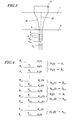
- an ultrasonic transmitted wave emitted from the ultrasonic probe 13 propagates as an ultrasonic beam 26 with a certain finite width through the extravascular tissue 1 and vascular wall 4.
- a portion of the ultrasonic wave is either reflected or scattered by the extravascular tissue 1 or the vascular wall 4 back toward the ultrasonic probe 13 and received there as an ultrasonic reflected wave.
- the ultrasonic reflected wave is detected as a time series signal r(t).
- the width (i.e., beam spot size) of the ultrasonic beam 26 can be controlled by changing the time delay.
- the ultrasonic reflected wave may be produced by both the extravascular tissue 1 and the vascular wall 4.
- the vascular wall tissue is the object of measurement in this preferred embodiment, the following description will be focused on only the reflection from the vascular wall 4.
- a plurality of measuring points P n which are located on an acoustic line 25 (i.e., the center axis of the ultrasonic beam) in the vascular wall 4, are arranged at regular intervals in the order of P 1 , P 2 , P 3 , ..., P k , ... and P n (where n is natural number that is equal to or greater than three) where P 1 is a located closest to the ultrasonic probe 13.
- the reflected wave signal r(t) has its phase detected by the phase detecting section 17 and the phase-detected signal is split into a real part signal and an imaginary part signal, which are then passed through the filter section 18.
- the computing section 19 calculates the phase difference by a minimum square method so as to minimize the waveform mismatch between the reflected wave signals r(t) and r(t+ ⁇ t). That is to say, the computing section 19 adopts a restricted minimum square method.
- the motion velocity V n (t) of the measuring point P n is derived from this phase difference and then integrated, thereby obtaining the magnitude of positional displacement d n (t).
- FIG. 4 shows the relationship between the measuring point P n and the tissue under measurement T n , of which the elasticity needs to be calculated.
- a tissue under measurement T k is located between two adjacent measuring points P k and P k+1 so as to have a thickness h. That is to say, a number (n-1) of tissues under measurement T 1 through T n-1 can be sampled from a number n of measuring points P 1 through P n .
- the thickness of the tissue T k of the vascular wall 4 varies when the blood flowing through the blood vessel, made up of the vascular wall 4, changes with the cardiac cycle.
- E k ( ⁇ p ⁇ H k ) / ⁇ h k
- H k the maximum thickness of the tissue under measurement T k (i.e., the value associated with the lowest blood pressure)
- ⁇ h k the difference between the maximum and minimum variations D k (t) in the thickness of the tissue under measurement
- ⁇ p pulse pressure that is the difference between the lowest and highest blood pressures.
- the elasticity is calculated between two adjacent measuring points.
- the elasticity may also be calculated between two arbitrary ones of the multiple measuring points. In that case, the elasticity can be calculated in a similar manner by using the maximum thickness and the maximum and minimum thickness variations between the two points selected.
- the tissue under measurement is a circulatory organ such as a vascular wall
- the greatest thickness difference ⁇ h, pulse pressure ⁇ p and maximum thickness H are all updated every cardiac cycle. That is why the elastic property is preferably evaluated in sync with every cardiac cycle.
- the maximum and minimum thickness variations in one cardiac cycle need to be obtained. According to the present invention, these maximum and minimum thickness variations are searched for in a period that is shorter than one cardiac cycle.
- the timings of measuring these numerical values will be described in detail.
- portions (d), (e) and (f) of FIG. 5 respectively show the magnitude of positional displacement, variation in thickness, and variation in the inside diameter of the blood vessel as measured by the ultrasonic diagnostic apparatus 11 at an arbitrary point on the vascular wall of a human carotid artery.
- portions (d), (e) and (f) of FIG. 5 respectively show the electrocardiogram, phonocardiogram and sphygmogram, which are biomedical signals obtained by measuring the displacements shown in graphs (a), (b) and (c) of FIG. 5.
- the abscissa represents the time. That is to say, these portions share the same time axis in common.
- the chart (g) of FIG. 5 shows the cardiac cycle phenomena on the time axis of graphs (a) through (f).
- one cardiac cycle is roughly divided into a systolic phase and a diastolic phase.
- the systolic phase is subdivided into a preejection period and an ejection period and the diastolic phase is subdivided into an isovolumetric relaxation period, a diastolic filling period and an atrial systolic period.
- the systolic phase substantially corresponds to a range that starts with the beginning of Q wave and terminates with the end of T wave on the electrocardiogram (i.e., graph (d) of FIG.
- the diastolic phase substantially corresponds to a range that starts with the end of T wave and terminates with the beginning of Q wave on the electrocardiogram and to a range that starts with the beginning of II sound and terminates with the beginning of I sound on the phonocardiogram.
- one cardiac cycle which is triggered by the beginning of a systolic phase as observed in a heart, is indicated by the dashed lines.
- the sphygmogram curve When blood is ejected from the heart, the sphygmogram curve rises steeply from S wave into P wave. After having reached the peak of the P wave, the sphygmogram curve makes a small upward hump of T wave, makes a notch of C wave, makes another small upward hump of D wave, and then falls gently.
- the C and D waves are called "dichrotic notch” and “dichrotic wave”, respectively, and are events brought about by the closure of the aortic valve.
- the thickness of the carotid artery shown in graph (b) of FIG.
- the maximum value b1 is encountered at the same time as the S wave of the sphygmogram, while the minimum value b2 is found at the same time as the P wave of the sphygmogram. That is to say, it can be seen that the greatest thickness difference ⁇ h does not have to be calculated in the overall cardiac cycle but in just a period in which the S and P waves of the sphygmogram are monitored. Likewise, the maximum and minimum blood pressures for calculating the pulse pressure ⁇ p can also be obtained from these S and P waves. Furthermore, the maximum thickness H can be obtained when the thickness variation reaches its maximum value b1.
- the elastic property of a circulatory organ such as the vascular wall of an organism can be measured in either a period including the ejection period and the ventricular systolic period (during which the S and P waves of the sphygmogram are observed) in one cardiac cycle or a period including at least a part of the ejection period and at least a part of the ventricular systolic period.
- no maximum or minimum thickness variation is present within the diastolic phase of one cardiac cycle. Accordingly, even if measurements were done in this phase to search for the maximum and minimum values, no desired maximum and minimum values should be obtained.
- the period for obtaining properly the maximum and minimum thickness variations within one cardiac cycle is set shorter than one cardiac cycle.
- the chances to recognize noise as the maximum or minimum value in error can be reduced. For example, if the measurements are done only within the ejection period of one cardiac cycle, then the chances to be affected by noise can be reduced to less than one third because the ejection period accounts for approximately 30% of one cardiac cycle.
- the computational complexity of the measurements can also be reduced.
- the manufacturing cost of the ultrasonic diagnostic apparatus can be cut down because there is no need to build a lot of memories in the ultrasonic diagnostic apparatus or to use any high-performance computer with high processing capabilities. Or an ultrasonic diagnostic apparatus that can get measurements done at high speed is realized.
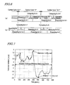
- Chart (a) of FIG. 6 shows the timings of measuring, calculating and presenting by the ultrasonic diagnostic apparatus of the present invention
- chart (b) of FIG. 6 shows the timings of measuring, calculating and presenting by a conventional ultrasonic diagnostic apparatus.
- the measuring period is a partial period of (i.e., shorter than) one cardiac cycle around an arbitrary cardiac cycle A.
- the partial period may be from R wave through T wave of the electrocardiogram shown in graph (d) of FIG. 5.
- the computing section 19 measures the magnitude of positional displacement and the variation in thickness.
- the display section 21 is presenting the results of the previous cardiac cycle A-1.
- the computing section 19 starts computation processing based on the results of measurements. More specifically, the computing section 19 extracts the maximum and minimum thickness variations, for example. Then, the elastic property calculated for the cardiac cycle A is presented on the display section 21.
- the cardiac cycle of the person under measurement is still "A". That is to say, the display section 21 starts to present the elastic property for the cardiac cycle A during the cardiac cycle A.
- the operator of the ultrasonic diagnostic apparatus 11 can check the results of computations for the cardiac cycle A in real time and can use them in measurements for the next cardiac cycle A+1. More specifically, the operator can finely adjust the location of the ultrasonic probe 13 or release the ultrasonic probe 13 once and then hold it again more firmly. As shown in the chart (a) of FIG. 6, by making the transmitting section 14 stop driving the ultrasonic probe 13 after the measurements have been done for the cardiac cycle A, the ultrasonic diagnostic apparatus 11 can stop the measurements.
- the load on a computer for controlling the ultrasonic diagnostic apparatus 11 can be lightened and the computations based on the results of measurements for the cardiac cycle A can be processed faster. As a result, the elastic property for the cardiac cycle A can be figured out more quickly.
- the computing section 19 stops computing until the next cardiac cycle A+1 begins.
- the computing section 19 may carry out any other type of signal processing (e.g., calculating the average of elastic properties at a number of most recent cardiac cycles) in this interval.
- the conventional ultrasonic diagnostic apparatus as disclosed in Patent Document No. 3, for example, carries out measurements throughout each cardiac cycle and then calculates the maximum and minimum thickness variations, the greatest thickness difference, and elastic property based on the measured values obtained as shown in chart (b) of FIG. 6. And these computations are done during the next cardiac cycle. More specifically, the conventional ultrasonic diagnostic apparatus carries out measurements during the cardiac cycle A and computations on the results of measurements during the next cardiac cycle A+1 as shown in the chart (b) of FIG. 6. In this case, the computation processing for the cardiac cycle A needs to be carried out in parallel with the measurements for the cardiac cycle A+1.
- Patent Document No. 3 discloses a technique of analyzing a big amplitude displacement/motion of a vascular wall under a restriction that the sum of displacements at one impulse becomes equal to zero in order to measure a very small motion of the blood vessel with stability and accuracy. According to Patent Document No. 3, the displacement/motion and variation in thickness need to be measured continuously all through one cardiac cycle. Patent Document No. 3 also discloses a technique of calculating the average elasticity E of the blood vessel based on the ratio of the pulse pressure (i.e., the difference between the highest and lowest blood pressures ps and pd) to the maximum strain A Emax.
- Patent Document No. 3 neither suggested nor taught calculating the maximum and minimum thickness variations in a partial period of one cardiac cycle.
- the times when the S and P waves of the sphygmogram are monitored and the times when the maximum and minimum thickness variations b1 and b2 are obtained can be set easily by using the biomedical signal.
- the electrocardiograph 22 is used as a biomedical signal detecting section as shown in graph (d) of FIG. 5, then the data acquisition period may be defined to last from R wave through T wave. That is to say, by regarding the R wave as a reference for starting the data acquisition period and the T wave as a reference for ending the data acquisition period, the maximum and minimum thickness variations can be obtained effectively.
- the R wave may be replaced with P wave, Q wave or S wave, or the data acquisition period may be defined to last 0.5 second from the R wave or to last a period of time accounting for 40% of one cardiac cycle from the R wave. Even so, similar effects are also achieved.
- the data acquisition period may be defined so as to last from I sound through II sound to obtain the maximum and minimum thickness variations effectively.
- the I sound may be replaced with IV sound or the II sound may be replaced with III sound.
- the data acquisition period may be defined to last 0.5 second from the I sound or to start earlier than the I sound by a period of time accounting for 10% of one cardiac cycle and to end later than the I sound by a period of time accounting for 30% of one cardiac cycle.
- the data acquisition period may be defined so as to last from S wave through C wave to obtain the maximum and minimum thickness variations effectively.
- the C wave may be replaced with T wave or D wave.
- the data acquisition period may be defined to last 0.5 second from the S wave or to start earlier than the S wave by a period of time corresponding to 10% of one cardiac cycle and to end later than the S wave by a period of time corresponding to 30% of one cardiac cycle.
- the numerical values measured by the ultrasonic diagnostic apparatus 11 may also be used as a trigger signal.
- graph (a) of FIG. 5 there are local maximum and minimum points such as the points a1, a2 and a3, where the magnitude of positional displacement changes uniquely, in the curve representing the magnitudes of positional displacement at arbitrary points on the carotid artery under measurement. That is why even if those points a1, a2 and a3 are extracted by the computing section 19, the period for obtaining the maximum and minimum thickness variations can also be defined within one cardiac cycle.
- the point a1 is an event resulting from a point with the lowest blood pressure at the measuring point on the blood vessel 3
- the point a2 is an event resulting from a point with the highest blood pressure at the measuring point on the blood vessel 3
- the point a3 is an event resulting from a dichrotic notch.
- the measuring period is defined based on the magnitudes of positional displacement, the maximum and minimum thickness variations can be easily obtained by setting the data acquisition period from the point a1 through the point a3, for example.
- the point a3 may be replaced with the point a2 .
- the data acquisition period may also be defined to last 0.5 second from the point a1 or to begin earlier than a1 by an amount of time corresponding to 10% of one cardiac cycle and end later than a2 by the same amount of time.
- the points c1, c2 and c3 may be extracted from the curve representing the variation in the inside diameter of the blood vessel and used for defining the measuring period.
- the points b1, b2 and b3 may be extracted from the curve representing the thickness variation shown in graph (b) of FIG. 5 and used for setting the measuring period.
- the electrocardiogram obtained by the electrocardiograph 22 may be input to the computing section 19 as shown in FIGS. 1 and 2. If the R wave is detected, the thickness variation may be calculated. But if the T wave is detected, then the calculation may be stopped as described above.
- the R and T waves may be detected by making the computing section 19 use the amplitude of the electrocardiogram, values obtained by differentiating the electrocardiogram, and their timings of appearance.
- the electrocardiograph 22 may also detect the R and T waves and may output a control signal to the computing section 19 on detecting those waves.
- the timing of a specific signal such as a waveform that triggers the biomedical signal is close to the timing at which the maximum or minimum thickness variation is obtained or if a specific signal that rises after the maximum or minimum thickness variation is reached is used as a trigger, then the signal may be used as a trigger in the measuring period of the next cardiac cycle that follows the period in which the specific signal was obtained as a trigger.
- the measuring period for obtaining the maximum and minimum thickness variations preferably has a length corresponding to 5% through 75% of one cardiac cycle.
- the reasons are as follows. Specifically, if the measuring period were shorter than 5% of one cardiac cycle, then at least one of the maximum and minimum thickness variations could not be obtained. However, if the measuring period were longer than 75% of one cardiac cycle, then the effects to be achieved by shortening the measuring period could not be achieved fully and the measurement could be subjected to noise more easily.
- the measuring period defined by using the biomedical signal as a trigger, preferably falls within this range. By setting the measuring period within this range, the computational complexity and the influence of noise would be reduced by approximately 25% to 95%.
- the variation in thickness is obtained as a difference in the magnitude of positional displacement between two points defining the thickness.
- the maximum and minimum thickness variations may be derived from the magnitudes of positional displacement between two points during the period in which the maximum and minimum thickness variations should be obtained.
- the ultrasonic diagnostic apparatus 11 may obtain the maximum and minimum thickness variations by measuring the magnitudes of positional displacement all through one cardiac cycle (i.e., continuously) and extracting some of the magnitudes of positional displacement that fall within the period for obtaining the maximum and minimum thickness variations.
- the ultrasonic diagnostic apparatus 11 may also obtain the maximum and minimum thickness variations by measuring the magnitudes of positional displacement only within the particular period of one cardiac cycle (i.e., intermittently).
- the maximum and minimum thickness variations may be calculated either in real time during that period defined by the biomedical signal, for example, or during some period that does not agree with that period.
- the magnitudes of positional displacement are preferably measured intermittently.
- the organism while diagnosed by the ultrasonic diagnostic apparatus, the organism is laid to rest and is likely to have little variation in cardiac rate. That is why the measuring period does not have to be defined every cardiac cycle.
- the measuring period may be repeated at the same intervals a number of times. Meanwhile, if the biomedical signal is detected every cardiac cycle and if the measuring period is defined based on that biomedical signal, then the elastic property can be evaluated just as intended even when the organism has an irregular cardiac cycle due to arrhythmia, for example.
- the measuring period is supposed to be set with the specific signal obtained by only one type of biomedical signal detecting section.
- the measuring period may also be defined by specific signal obtained by a plurality of biomedical signal detecting sections.
- the R wave of the electrocardiogram may be used as a signal that defines the beginning of a measuring period and the point c3 of the variation in the inside diameter of the blood vessel may be used as a signal that defines the end of the measuring period.
- the greatest thickness difference is obtained by finding the maximum and minimum thickness variations.
- the thicknesses themselves may be measured and the greatest thickness difference may be obtained from the maximum and minimum thicknesses.
- the thickness variation is already known. In that case, if the thickness when the thickness variation starts to be measured is known, then the variation in thickness with time can be obtained as the sum of the thickness at the start of measuring and the thickness variation.
- the thickness at the start of measuring is nothing but the initial value of the distance between two arbitrary points to calculate the magnitudes of positional displacement for, and is a known parameter for the ultrasonic diagnostic apparatus 11 of this preferred embodiment.
- a waveform to be a trigger signal for setting the measuring period may be presented on the display section 21 and the measuring period may be highlighted on that waveform. Then the operator of the apparatus can easily check out the period for obtaining the maximum and minimum thicknesses or the maximum and minimum thickness variations. If the measuring period presented is different from the desired measuring period, the operator may modify the measuring period into the desired one either by manually finely adjusting the measuring period or by changing the source of the trigger signal.
- FIG. 6 shows the variation in the thickness of the rear wall of a human carotid artery, which was measured with the ultrasonic diagnostic apparatus 11.
- the person under measurement was a 41-year-old man and the variation was measured for one cardiac cycle (of about 800 ms) using the R wave of his electrocardiogram as a trigger signal.
- FIG. 7 shows the variation in the thickness of the rear wall of the same human carotid artery as that of FIG. 6.
- the period for obtaining the maximum and minimum thickness variations is changed to last 300 ms from the R wave trigger signal, then correct maximum and minimum values can be selected.
- the data acquisition period can be shortened to about three-eighths, and therefore, the memory for storing the data acquired can have smaller capacity and the computer needs to do computations of reduced complexity per cardiac cycle. Consequently, the memory to be built in the ultrasonic diagnostic apparatus can have a reduced capacity and the elastic property can be evaluated faster.
- a computer with low computation performance may also be adopted since the computational complexity has been reduced. Then, the cost of the ultrasonic diagnostic apparatus can be cut down.
- the ultrasonic diagnostic apparatus of the present invention calculates the maximum and minimum thickness variations based on the magnitude of positional displacement in a period that is shorter than one cardiac cycle.
- the apparatus can obtain more accurate measuring results with the influence of noise minimized.
- the ultrasonic diagnostic apparatus of the present invention can be used effectively to evaluate the elastic property of a vital tissue.
- the apparatus can be used particularly effectively to detect or prevent the disease of arterial sclerosis by measuring the elastic property of a vascular wall.
Landscapes
- Health & Medical Sciences (AREA)
- Life Sciences & Earth Sciences (AREA)
- Heart & Thoracic Surgery (AREA)
- Surgery (AREA)
- Physics & Mathematics (AREA)
- Veterinary Medicine (AREA)
- Biophysics (AREA)
- Pathology (AREA)
- Engineering & Computer Science (AREA)
- Biomedical Technology (AREA)
- Public Health (AREA)
- Medical Informatics (AREA)
- Molecular Biology (AREA)
- General Health & Medical Sciences (AREA)
- Animal Behavior & Ethology (AREA)
- Physiology (AREA)
- Vascular Medicine (AREA)
- Cardiology (AREA)
- Nuclear Medicine, Radiotherapy & Molecular Imaging (AREA)
- Radiology & Medical Imaging (AREA)
- Dentistry (AREA)
- Oral & Maxillofacial Surgery (AREA)
- Ultra Sonic Daignosis Equipment (AREA)
Abstract
Description
- The present invention relates to an ultrasonic diagnostic apparatus for measuring the elastic property of a vital tissue using an ultrasonic wave and also relates to a method for controlling such an ultrasonic diagnostic apparatus.
- Recently, the number of people suffering from various circulatory system diseases, including heart infarction and brain infarction, has been on the rise, thus making it more and more urgent to prevent and treat these diseases.
- The pathopoiesis of heart or brain infarction is closely correlated to arterial sclerosis. More specifically, if an atheroma is created on the arterial wall or if no arterial cells are produced anymore due to various factors such as elevated blood pressure, then the artery loses its elasticity to become hard and fragile. Also, if the blood vessel is clogged up where the atheroma has been created or if a vascular tissue covering the atheroma has ruptured, then the atheroma will move itself into the blood vessel to clog up the artery elsewhere or to rupture the hardened portions of the artery. As a result, these diseases are caused. That is why it is important to diagnose the arterial sclerosis as early as possible to prevent or treat these diseases.
- If the arterial sclerosis can be diagnosed early enough to administer some medicine to its patient, then the disease can be treated effectively. However, it is said that once the arterial sclerosis has advanced to a certain degree, the farther advancement of that disease can be checked with the administration of medicine but it is difficult to repair the hardened artery completely.
- In the prior art, the lesion of arterial sclerosis is diagnosed by directly observing the inside of the blood vessel with a vascular catheter. However, this diagnosis needs to be carried out with a vascular catheter inserted into the blood vessel of a patient, thus imposing a heavy load on him or her. For that reason, the vascular catheter observation is usually adopted to locate the lesion of arterial sclerosis in a patient who is already known to suffer from that disease but has never been used to make a medical checkup on a supposedly healthy person.
- A checkup may be easily made without imposing excessively heavy load on a patient if the index of cholesterol, which is one of major causes of arterial sclerosis, or the blood pressure is measured. However, none of these values directly indicates the degree of advancement of arterial sclerosis.
- That is why a method or apparatus for diagnosing the arterial sclerosis at an early stage of its advancement without imposing too much load on its patient is now in high demand.
- An ultrasonic diagnostic apparatus has been used in the prior art as a medical apparatus that imposes only a light load on its patient. Specifically, by irradiating the patient with an ultrasonic wave that has been produced externally by the ultrasonic diagnostic apparatus, geometric information, mobility information or quality information of his or her internal body can be acquired without causing pain to him or her.
- Among other things, if ultrasonic measurement is carried out on an object, then mobility information of the object can be acquired. Thus, the elastic property of the object can be estimated by the magnitude of positional displacement of the object. That is to say, in this case, the elastic property of the blood vessel of an organism can be evaluated and the degree of advancement of arterial sclerosis can be known directly. On top of that, the measurement can be done just by putting an ultrasonic probe on a patient, and very little load is placed on him or her. For that reason, if the ultrasonic diagnostic apparatus is used, the arterial sclerosis could be diagnosed accurately and a preventive checkup could be carried out on a person under measurement without imposing excessive load on him or her.
- However, conventional ultrasonic diagnostic apparatuses, including one for observing the shape of an embryo or making auscultation on his or her heartbeat, do not usually achieve sufficiently high resolutions in terms of geometric information and mobility information. That is why it is impossible to figure out the elastic property of an artery, which expands and shrinks in sync with a cardiac cycle, using a conventional ultrasonic diagnostic apparatus. For example, as disclosed in Patent Document No. 1, most of conventional ultrasonic diagnostic apparatuses cannot measure the displacement of the object sufficiently accurately.
- Recently, however, some ultrasonic diagnostic apparatuses can have significantly improved measuring accuracy thanks to remarkable advancement of electronic technologies. As a result, ultrasonic diagnostic apparatuses for measuring the very small motion of a vital tissue have been developed. For example, Patent Document No. 2 discloses an ultrasonic diagnostic apparatus for tracking the phase with high accuracy by determining the instantaneous location of an object by a restricted minimum square method using both the amplitude and phase of a detection signal. This apparatus can measure the very small vibration of a tissue that is moving greatly due to pulsations. According to Patent Document No. 2, the very small vibrations with frequencies of several hundreds of Hz or less, which are included in a displacement motion caused by a pulsation with a huge amplitude of 10 mm or more, can be measured with good enough reproducibility even if the pulsations are repeated about 10 times.
- The apparatuses disclosed in Patent Documents Nos. 2 and 3 can measure high frequency components up to several hundreds of Hz with good reproducibility and converge an ultrasonic beam, thereby evaluating the elastic property of an area with a diameter of about 1 to 2 mm on a cardiac muscle or arterial wall. In addition, those apparatuses are reported to have excellent features in that the apparatuses can obtain an ultrasonic signal with a component of any time phase and can analyze the frequency spectrum of that signal during one cardiac cycle.
- Therefore, an ultrasonic diagnostic apparatus according to the techniques disclosed in these documents is expected to check the degree of advancement of arterial sclerosis with time without imposing heavy load on a person under a physical checkup, for example, and eventually prevent any disease caused by the arterial sclerosis. The apparatus is also expected to locate a region where the blood vessel ruptures easily and to treat that region by measuring the elastic property of a very small area of the artery.
- Patent Document No. 1: Japanese Patent Application Laid-Open Publication No. 62-266040
- Patent Document No. 2: Japanese Patent Application Laid-Open Publication No. 10-5226 and
- Patent Document No. 3: Japanese Patent Application Laid-Open Publication No. 2000-229078
- As described above, in evaluating the elastic property of a substance using an ultrasonic wave, the mobility information of the object under measurement is acquired. Suppose the elastic property of a vital tissue (e.g., the elastic property of a vascular wall, among other things) should be evaluated one cardiac cycle after another. In that case, the elastic property E of the vascular wall may be given by:

where Δp is the difference between the maximum and minimum blood pressure values, Δ h is the greatest thickness difference of the vascular wall during an arbitrary cardiac cycle, and H is the maximum thickness of the vascular wall. - Among these values, the maximum and minimum blood pressure values are obtained by measuring the blood pressure with a blood pressure manometer, for example. Meanwhile, the greatest thickness difference Δ h of the vascular wall is calculated based on the maximum and minimum thickness variations of the vascular wall as measured by the method of Patent Document No. 2 mentioned above, for example.
- However, if some noise, of which the magnitude exceeds the maximum and minimum thickness variations, were caused during the ultrasonic wave measurement, then a wrong greatest thickness difference, different from its actual value, would be obtained in error and the elastic property could not be evaluated properly.
- What is more, this computation needs to be carried out by a computer of which the processing performance is much higher than that of a conventional ultrasonic diagnostic apparatus for displaying the shape of a vital tissue. That is why the overall price of an apparatus including such a high-performance computer goes rather high. Nevertheless, if a computer with just moderate processing performance is used, then it will take a lot of time to get the computations done, thus causing a time lag before presenting the results of measurement.
- In order to overcome at least one of these problems, an object of the present invention is to provide an ultrasonic diagnostic apparatus that can accurately measure the elastic property with the influence of noise minimized.
- An ultrasonic diagnostic apparatus according to the present invention includes: a transmitting section for driving an ultrasonic probe that sends out an ultrasonic transmitted wave toward a body tissue of an organism; a receiving section for receiving an ultrasonic reflected wave through the ultrasonic probe, the ultrasonic reflected wave being produced by getting the ultrasonic transmitted wave reflected by the body tissue; a phase detecting section for detecting the phase of the ultrasonic reflected wave; and a computing section for calculating the magnitudes of positional displacement at a plurality of measuring points on the body tissue based on a signal obtained by the phase detecting section and also figuring out the greatest thickness difference between two of the measuring points and/or an elastic property based on the magnitudes of positional displacement. The computing section figures out either the maximum and minimum thicknesses or thickness variations between the two points based on the magnitudes of positional displacement at the two points during a partial period of one cardiac cycle of the organism, and also calculates the greatest thickness difference and/or elastic property as the difference between the maximum and minimum values.
- In a preferred embodiment, the body tissue is a circulatory organ, and the computing section receives information about a blood pressure value of the organism and figures out the elastic property based on the blood pressure value.
- In another preferred embodiment, the partial period of the one cardiac cycle is set in sync with a biomedical signal obtained from the organism.
- In a specific preferred embodiment, the biomedical signal is represented as an electrocardiogram by an electrocardiograph.
- In this particular preferred embodiment, the partial period of the one cardiac cycle is set based on at least one of P, Q, R, S, T and U waves of the electrocardiogram.
- In an alternative preferred embodiment, the partial period of the one cardiac cycle is set based on the R and T waves of the electrocardiogram.
- In still another preferred embodiment, the biomedical signal is represented as a phonocardiogram by a phonocardiograph.
- In this particular preferred embodiment, the partial period of the one cardiac cycle is set based on at least one of I, II, III and IV sounds of the phonocardiogram.
- In yet another preferred embodiment, the biomedical signal is represented as a sphygmogram by a sphygmograph.
- In this particular preferred embodiment, the partial period of the one cardiac cycle is set based on at least one of S, P, T, C and D waves of the sphygmogram.
- In yet another preferred embodiment, the computing section calculates in advance a positional displacement waveform, showing the magnitude of positional displacement of the body tissue during the one cardiac cycle, and sets the partial period of the one cardiac cycle based on the positional displacement waveform.
- In yet another preferred embodiment, the computing section calculates in advance a thickness variation waveform, showing a variation in the thickness of the body tissue during the one cardiac cycle, according to the magnitude of positional displacement and sets the partial period of the one cardiac cycle based on the thickness variation waveform.
- In yet another preferred embodiment, the computing section calculates in advance a vascular caliber variation waveform, showing a variation in the vascular caliber of the body tissue during the one cardiac cycle, according to the magnitude of positional displacement and sets the partial period of the one cardiac cycle based on the vascular caliber variation waveform.
- In yet another preferred embodiment, the partial period accounts for 5% to 75% of the one cardiac cycle.
- In yet another preferred embodiment, the ultrasonic diagnostic apparatus further includes a display section for displaying the greatest thickness difference and/or elastic property. The computing section calculates the greatest thickness difference and/or elastic property during the rest of the one cardiac cycle after the partial period has expired. And the display section starts to display the greatest thickness difference and/or elastic property during the one cardiac cycle including the partial period.
- In this particular preferred embodiment, the transmitting section drives the ultrasonic probe during the partial period of the one cardiac cycle and stops driving the ultrasonic probe during the rest of the one cardiac cycle.
- A method for controlling an ultrasonic diagnostic apparatus according to the present invention is carried out by the control section of the apparatus. The method includes the steps of: transmitting an ultrasonic wave and receiving an ultrasonic reflected wave, which is produced by getting the ultrasonic wave reflected by a body tissue of an organism; detecting the phase of the ultrasonic reflected wave; and calculating the magnitudes of positional displacement at a plurality of measuring points on the body tissue based on a signal obtained by the phase detecting step and also figuring out the greatest thickness difference between two of the measuring points and/or an elastic property based on the magnitudes of positional displacement. The step of calculating includes figuring out either the maximum and minimum thicknesses or thickness variations between the two points based on the magnitudes of positional displacement at the two points during a partial period of one cardiac cycle of the organism, and also calculating the greatest thickness difference and/or elastic property as the difference between the maximum and minimum values.
- In one preferred embodiment, the body tissue is a circulatory organ, and the step of computing includes figuring out the elastic property based on a blood pressure value of the organism.
- In this particular preferred embodiment, the partial period of the one cardiac cycle is set in sync with a biomedical signal obtained from the organism.
- In a specific preferred embodiment, the biomedical signal is represented as an electrocardiogram by an electrocardiograph.
- More specifically, the partial period of the one cardiac cycle is set based on at least one of P, Q, R, S, T and U waves of the electrocardiogram.
- Alternatively, the partial period of the one cardiac cycle is set based on the R and T waves of the electrocardiogram.
- In still another preferred embodiment, the biomedical signal is represented as a phonocardiogram by a phonocardiograph.
- In this particular preferred embodiment, the partial period of the one cardiac cycle is set based on at least one of I, II, III and IV sounds of the phonocardiogram.
- In yet another preferred embodiment, the biomedical signal is represented as a sphygmogram by a sphygmograph.
- In this particular preferred embodiment, the partial period of the one cardiac cycle is set based on at least one of S, P, T, C and D waves of the sphygmogram.
- In yet another preferred embodiment, the step of computing includes calculating in advance a positional displacement waveform, showing the magnitude of positional displacement of the body tissue during the one cardiac cycle, and setting the partial period of the one cardiac cycle based on the positional displacement waveform.
- In yet another preferred embodiment, the step of computing includes calculating in advance a thickness variation waveform, showing a variation in the thickness of the body tissue during the one cardiac cycle, according to the magnitude of positional displacement and setting the partial period of the one cardiac cycle based on the thickness variation waveform.
- In yet another preferred embodiment, the step of computing includes calculating in advance a vascular caliber variation waveform, showing a variation in the vascular caliber of the body tissue during the one cardiac cycle, according to the magnitude of positional displacement and setting the partial period of the one cardiac cycle based on the vascular caliber variation waveform.
- In yet another preferred embodiment, the partial period of the one cardiac cycle includes at least a part, and sometimes all, of an ejection period.
- In an alternative preferred embodiment, the partial period of the one cardiac cycle includes at least a part, and sometimes all, of a systolic phase.
- In yet another preferred embodiment, the partial period accounts for 5% to 75% of the one cardiac cycle.
- In yet another preferred embodiment, the method further includes the step of displaying the greatest thickness difference and/or elastic property. The step of computing includes calculating the greatest thickness difference and/or elastic property during the rest of the one cardiac cycle after the partial period has expired. And the step of displaying includes starting to display the greatest thickness difference and/or elastic property during the one cardiac cycle including the partial period.
- In yet another preferred embodiment, the step of transmitting the ultrasonic wave and receiving the ultrasonic reflected wave is carried out during the partial period of the one cardiac cycle but stopped during the rest of the one cardiac cycle.
- According to the present invention, the computing section figures out either the maximum and minimum thicknesses or the maximum and minimum thickness variations based on the magnitudes of positional displacement during a partial period of one cardiac cycle of an organism, and also figures out the elastic property using the maximum and minimum values obtained. As a result, the elastic property can be measured accurately with the influence of noise reduced.
-
- FIG. 1 is a block diagram showing an arrangement for a situation where an ultrasonic diagnostic apparatus according to the present invention is used to diagnose the tissue and attribute of a vascular wall.
- FIG. 2 is a block diagram showing a configuration for the ultrasonic diagnostic apparatus of the present invention.
- FIG. 3 schematically illustrates an ultrasonic beam propagating through a body tissue.
- FIG. 4 shows the relationship between the measuring point and the elasticity at the measuring point.
- Graphs (a), (b) and (c) of FIG. 5 show the magnitude of positional displacement, variation in thickness and variation in the inside diameter of the blood vessel as measured on a human carotid artery by the ultrasonic diagnostic apparatus of the present invention; graphs (d), (e) and (f) of FIG. 5 show an electro-cardiogram, a phonocardiogram and a sphygmogram; and chart (g) of FIG. 5 shows phenomena occurring in one cardiac cycle.
- Chart (a) of FIG. 6 shows the timings of measuring, calculating and presenting by the ultrasonic diagnostic apparatus of the present invention, while chart (b) of FIG. 6 shows the timings of measuring, calculating and presenting by a conventional ultrasonic diagnostic apparatus.
- FIG. 7 is a graph showing a variation in the thickness of the rear wall of a human carotid artery with time.
- FIG. 8 is a graph showing a variation in the thickness of the rear wall of a human carotid artery with time where the period for searching for the maximum and minimum thickness variations is set shorter than one cardiac cycle.
-
- 1
- body tissue
- 2
- body surface
- 3
- blood vessel
- 4
- vascular wall
- 5
- blood
- 11
- ultrasonic diagnostic apparatus
- 12
- blood pressure manometer
- 13
- ultrasonic probe
- 14
- transmitting section
- 15
- receiving section
- 16
- time delay control section
- 17
- phase detecting section
- 18
- filter
- 19
- computing section
- 20
- computed data storage section
- 21
- display section
- 22
- electrocardiograph
- An ultrasonic diagnostic apparatus according to the present invention estimates the motion velocity of each portion of an object under measurement and also figures out the greatest thickness difference and elastic property of each very small area. The ultrasonic diagnostic apparatus of the present invention can be used particularly effectively to evaluate the elastic property of each portion of an organism and also has sufficiently high spatial resolution. That is why the ultrasonic diagnostic apparatus of the present invention is preferably used to figure out the greatest thickness difference and elastic property of a vascular wall. Thus, an ultrasonic diagnostic apparatus according to a preferred embodiment of the present invention will be described as being applied to figuring out the greatest thickness difference and elastic property of a vascular wall.
- FIG. 1 is a block diagram showing an arrangement for a situation where the ultrasonic
diagnostic apparatus 11 of the present invention is used to diagnose the tissue and attribute of a vascular wall. Anultrasonic probe 13, connected to the ultrasonicdiagnostic apparatus 11, is put in close contact with thebody surface 2 of a person under measurement and transmits an ultrasonic wave into a body tissue including anextravascular tissue 1 and ablood vessel 3. Theextravascular tissue 1 is made up of fats, muscles and so on. The transmitted ultrasonic wave is reflected by theblood vessel 3 andblood 5, scattered, and only a portion of it comes back to, and is received as an echo by, theultrasonic probe 13. Theultrasonic probe 13 may be a known ultrasonic probe, which includes an array of ultrasonic vibrators (i.e., a group of ultrasonic vibrators) and which is used in a conventional ultrasonic diagnostic apparatus. The ultrasonicdiagnostic apparatus 11 performs analysis and computations on a received signal, thereby acquiring the mobility information of thevascular wall 4. Also, ablood pressure manometer 12 is connected to the ultrasonicdiagnostic apparatus 11 such that data about the blood pressure values of the person under measurement, collected by theblood pressure manometer 12, is input to the ultrasonicdiagnostic apparatus 11. - In accordance with the method disclosed in Patent Document No. 2, the ultrasonic
diagnostic apparatus 11 determines the instantaneous position of the object by a restricted minimum square method using both the amplitude and phase of a detection signal, thereby performing phase tracking highly accurately (where the magnitude of positional displacement has a measuring accuracy of about ± 0.2 µm) and measuring variations in the position and thickness of a very small spot on thevascular wall 4 with time. In addition, by using blood pressure data obtained with theblood pressure manometer 12, the ultrasonicdiagnostic apparatus 11 can also evaluate the elastic property of a very small spot on thevascular wall 4. - An
electrocardiograph 22 is connected to the ultrasonicdiagnostic apparatus 11, which receives an electrocardiogram from theelectrocardiograph 22 and uses it as a trigger signal that determines the timings of data acquisition and data resetting. More particularly, the ultrasonicdiagnostic apparatus 11 sets a partial period of one cardiac cycle of the organism using the electrocardiogram and evaluates the elastic property according to only the information collected during the designated partial period. In this manner, the influence of noise can be reduced and the elastic property can be evaluated highly accurately. - Hereinafter, the configuration and operation of the ultrasonic
diagnostic apparatus 11 will be described in detail. FIG. 2 is a block diagram showing a configuration for the ultrasonicdiagnostic apparatus 11. The ultrasonicdiagnostic apparatus 11 includes a transmittingsection 14, a receivingsection 15, a timedelay control section 16, aphase detecting section 17, afilter 18, acomputing section 19, a computeddata storage section 20, and adisplay section 21. The ultrasonicdiagnostic apparatus 11 further includes a control section 50 (implemented as a computer, for example) for performing an overall control on all of these sections. - The transmitting
section 14 generates a predetermined drive pulse signal and outputs it to theultrasonic probe 13. An ultrasonic transmitted wave, transmitted by theultrasonic probe 13 in response to the drive pulse signal, is reflected and scattered by a body tissue such as thevascular wall 4 to produce an ultrasonic reflected wave, which is then received at theultrasonic probe 13. - The receiving
section 15 receives the ultrasonic reflected wave through theultrasonic probe 13, and includes an A/D converting section for amplifying the ultrasonic reflected wave and then converting the amplified wave into a digital signal. The transmittingsection 14 and receivingsection 15 may be made of electronic components, for example. - The time
delay control section 16 is connected to the transmittingsection 14 and receivingsection 15 in order to control the time delay of the drive pulse signal to be supplied from the transmittingsection 14 to a group of ultrasonic vibrators in theultrasonic probe 13. In this manner, an ultrasonic beam of the ultrasonic transmitted wave to be transmitted from theultrasonic probe 13 can have its acoustic line direction and depth of focus changed. Also, by controlling the time delay of a received reflected wave signal that has been received by theultrasonic probe 13 and then amplified by the receivingsection 15, the acoustic line direction of the ultrasonic wave to receive can be changed. The output of the timedelay control section 16 is passed to thephase detecting section 17. - The
phase detecting section 17 detects the phase of the received reflected wave signal, of which the time delay has been controlled by the timedelay control section 16, thereby splitting the signal into a real part signal and an imaginary part signal, which are then input to thefilter section 18. Thefilter section 18 filters out components that have not been reflected by the object of measurement and other noise components. Thephase detecting section 17 andfilter section 18 may be implemented as either a software program or hardware components. - The
computing section 19 calculates the motion velocities at a plurality of tracking points that have been set inside of thevascular wall 4 by using the real part and imaginary part signals of the phase-detected signal and then integrates these motion velocities together, thereby figuring out the magnitudes of displacement with time at the respective tracking points inside of thevascular wall 4. Then, thecomputing section 19 selectively calculates the difference in the magnitude of positional displacement between two arbitrary points among those magnitudes of positional displacement, thereby obtaining the difference in thickness between those two points. Furthermore, based on the greatest thickness difference obtained as the difference between the maximum and minimum thickness variations thus calculated and on the blood pressure data collected with theblood pressure manometer 12, thecomputing section 19 can evaluate the elastic property of the tissue located between the two points. The electrocardiogram obtained by theelectrocardiograph 22 is input to thecomputing section 19 and used as a trigger signal for determining the timings of data acquisition and data resetting. For this purpose, theelectrocardiograph 22 may be replaced with any other biomedical signal detecting means such as a phonocardiograph or a sphygmograph. In that case, a phonocardiogram or a sphygmogram may be used as a trigger signal instead of the electrocardiogram. - Data about the magnitudes of positional displacement, variations in thickness, and elastic property that have been figured out by the
computing section 19 may be stored in, and readily read out from, the computeddata storage section 20, and may also be input to thedisplay section 21 so as to be visualized into a two-dimensional image. Furthermore, if thedisplay section 21 is connected to the computeddata storage section 20, those various data stored may also be presented on thedisplay section 21 when required. Those data computed by thecomputing section 19 are preferably output to both thedisplay section 21 and thestorage section 20 so as to be presented in real time and saved for future use at the same time. However, one of thedisplay section 21 and thestorage section 20 may be omitted as well. - Next, it will be described in detail with reference to FIG. 3 how to calculate the magnitude of positional displacement of a body tissue. As shown in FIG. 3, an ultrasonic transmitted wave, emitted from the
ultrasonic probe 13, propagates as anultrasonic beam 26 with a certain finite width through theextravascular tissue 1 andvascular wall 4. In the meantime, a portion of the ultrasonic wave is either reflected or scattered by theextravascular tissue 1 or thevascular wall 4 back toward theultrasonic probe 13 and received there as an ultrasonic reflected wave. The ultrasonic reflected wave is detected as a time series signal r(t). The closer to the ultrasonic probe 13 a portion of the tissue that has reflected the ultrasonic wave to produce the time series signal, the closer to the origin the signal is located on the time axis. The width (i.e., beam spot size) of theultrasonic beam 26 can be controlled by changing the time delay. - As described above, the ultrasonic reflected wave may be produced by both the
extravascular tissue 1 and thevascular wall 4. However, since the vascular wall tissue is the object of measurement in this preferred embodiment, the following description will be focused on only the reflection from thevascular wall 4. A plurality of measuring points Pn, which are located on an acoustic line 25 (i.e., the center axis of the ultrasonic beam) in thevascular wall 4, are arranged at regular intervals in the order of P1, P2, P3, ..., Pk, ... and Pn (where n is natural number that is equal to or greater than three) where P1 is a located closest to theultrasonic probe 13. Supposing the coordinates that are defined in the depth direction with respect to the surface of theextravascular tissue 1 as the origin are represented by Z1, Z2, Z3, ..., Zk, ... and Zn, an ultrasonic wave reflected from a measuring point Pk is located at tk = 2Zk/c on the time axis, where c is the velocity of the ultrasonic wave in the body tissue. The reflected wave signal r(t) has its phase detected by thephase detecting section 17 and the phase-detected signal is split into a real part signal and an imaginary part signal, which are then passed through thefilter section 18. Under the restriction that the amplitude does not change, but only the phase and reflection spot change, between the reflected wave signal r(t) and another reflected wave signal r(t + Δ t) obtained after a very small amount of time Δt, thecomputing section 19 calculates the phase difference by a minimum square method so as to minimize the waveform mismatch between the reflected wave signals r(t) and r(t+Δt). That is to say, thecomputing section 19 adopts a restricted minimum square method. The motion velocity Vn(t) of the measuring point Pn is derived from this phase difference and then integrated, thereby obtaining the magnitude of positional displacement dn(t). - FIG. 4 shows the relationship between the measuring point P n and the tissue under measurement Tn, of which the elasticity needs to be calculated. A tissue under measurement T k is located between two adjacent measuring points P k and P k+1 so as to have a thickness h. That is to say, a number (n-1) of tissues under measurement T 1 through T n-1 can be sampled from a number n of measuring points P 1 through P n .
- The variation D k (t) in the thickness of the tissue under measurement T k (i.e., the magnitude of its stretch or shrinkage) is obtained as the difference between the magnitudes of positional displacement d k (t) and d k+1 (t) of the measuring points P k and P k+1 (i.e., Dk(t)=dk+1(t)-dk(t)). The thickness of the tissue T k of the
vascular wall 4 varies when the blood flowing through the blood vessel, made up of thevascular wall 4, changes with the cardiac cycle. Accordingly, the elasticity E k (i.e., the strain rate) of the tissue under measurement T k in the vascular radial direction is given by:
- In the example described above, the elasticity is calculated between two adjacent measuring points. However, the elasticity may also be calculated between two arbitrary ones of the multiple measuring points. In that case, the elasticity can be calculated in a similar manner by using the maximum thickness and the maximum and minimum thickness variations between the two points selected.
- If the tissue under measurement is a circulatory organ such as a vascular wall, then the greatest thickness difference Δh, pulse pressure Δp and maximum thickness H are all updated every cardiac cycle. That is why the elastic property is preferably evaluated in sync with every cardiac cycle. To calculate the greatest thickness difference Δh in one cardiac cycle, the maximum and minimum thickness variations in one cardiac cycle need to be obtained. According to the present invention, these maximum and minimum thickness variations are searched for in a period that is shorter than one cardiac cycle. Hereinafter, the timings of measuring these numerical values will be described in detail. Graphs (a), (b) and (c) of FIG. 5 respectively show the magnitude of positional displacement, variation in thickness, and variation in the inside diameter of the blood vessel as measured by the ultrasonic
diagnostic apparatus 11 at an arbitrary point on the vascular wall of a human carotid artery. On the other hand, portions (d), (e) and (f) of FIG. 5 respectively show the electrocardiogram, phonocardiogram and sphygmogram, which are biomedical signals obtained by measuring the displacements shown in graphs (a), (b) and (c) of FIG. 5. In all of these graphs (a) through (f) of FIG. 5, the abscissa represents the time. That is to say, these portions share the same time axis in common. Meanwhile, the chart (g) of FIG. 5 shows the cardiac cycle phenomena on the time axis of graphs (a) through (f). - As shown in the chart (g) of FIG. 5, one cardiac cycle is roughly divided into a systolic phase and a diastolic phase. The systolic phase is subdivided into a preejection period and an ejection period and the diastolic phase is subdivided into an isovolumetric relaxation period, a diastolic filling period and an atrial systolic period. The systolic phase substantially corresponds to a range that starts with the beginning of Q wave and terminates with the end of T wave on the electrocardiogram (i.e., graph (d) of FIG. 5) and to a range that starts with the beginning of I sound and terminates with the end of II sound on the phonocardiogram (i.e., graph (e) of FIG. 5). On the other hand, the diastolic phase substantially corresponds to a range that starts with the end of T wave and terminates with the beginning of Q wave on the electrocardiogram and to a range that starts with the beginning of II sound and terminates with the beginning of I sound on the phonocardiogram. In FIG. 5, one cardiac cycle, which is triggered by the beginning of a systolic phase as observed in a heart, is indicated by the dashed lines.
- The magnitude of positional displacement, variation in thickness and variation in the inside diameter of the blood vessel shown in graphs (a), (b) and (c) of FIG. 5 and the sphygmogram shown in graph (f) if FIG. 5 are measured at the carotid artery, which is located away from the heart. That is why when about 0.1 second has passed after various events of one cardiac cycle have occurred in the heart, phenomena corresponding to these events of the heart are observed on these magnitudes of displacement and a sphygmogram. For example, the systolic phase of the sphygmogram (see graph (f) of FIG. 5) starts with S wave but its timing trails by about 0.1 second behind the beginning of the systolic phase as indicated by the dashed line. In FIG. 5, one cardiac cycle, which is triggered by the beginning of a systolic phase as observed in the carotid artery, is indicated by the one dot chain.
- When blood is ejected from the heart, the sphygmogram curve rises steeply from S wave into P wave. After having reached the peak of the P wave, the sphygmogram curve makes a small upward hump of T wave, makes a notch of C wave, makes another small upward hump of D wave, and then falls gently. The C and D waves are called "dichrotic notch" and "dichrotic wave", respectively, and are events brought about by the closure of the aortic valve. In the variation in the thickness of the carotid artery shown in graph (b) of FIG. 5, the maximum value b1 is encountered at the same time as the S wave of the sphygmogram, while the minimum value b2 is found at the same time as the P wave of the sphygmogram. That is to say, it can be seen that the greatest thickness difference Δh does not have to be calculated in the overall cardiac cycle but in just a period in which the S and P waves of the sphygmogram are monitored. Likewise, the maximum and minimum blood pressures for calculating the pulse pressure Δp can also be obtained from these S and P waves. Furthermore, the maximum thickness H can be obtained when the thickness variation reaches its maximum value b1.
- Consequently, the elastic property of a circulatory organ such as the vascular wall of an organism can be measured in either a period including the ejection period and the ventricular systolic period (during which the S and P waves of the sphygmogram are observed) in one cardiac cycle or a period including at least a part of the ejection period and at least a part of the ventricular systolic period. Stated otherwise, no maximum or minimum thickness variation is present within the diastolic phase of one cardiac cycle. Accordingly, even if measurements were done in this phase to search for the maximum and minimum values, no desired maximum and minimum values should be obtained.
- According to the present invention, by taking advantage of such a tendency of the thickness variation, the period for obtaining properly the maximum and minimum thickness variations within one cardiac cycle is set shorter than one cardiac cycle. By adopting such a shortened measuring time, the chances to recognize noise as the maximum or minimum value in error can be reduced. For example, if the measurements are done only within the ejection period of one cardiac cycle, then the chances to be affected by noise can be reduced to less than one third because the ejection period accounts for approximately 30% of one cardiac cycle. In addition, by shortening the measuring time, the computational complexity of the measurements can also be reduced. As a result, the manufacturing cost of the ultrasonic diagnostic apparatus can be cut down because there is no need to build a lot of memories in the ultrasonic diagnostic apparatus or to use any high-performance computer with high processing capabilities. Or an ultrasonic diagnostic apparatus that can get measurements done at high speed is realized.
- On top of that, the thickness difference and elastic property calculated can be presented on the
display section 21 even before one cardiac cycle is completed. Chart (a) of FIG. 6 shows the timings of measuring, calculating and presenting by the ultrasonic diagnostic apparatus of the present invention, while chart (b) of FIG. 6 shows the timings of measuring, calculating and presenting by a conventional ultrasonic diagnostic apparatus. As shown in the chart (a) of FIG. 6, the measuring period is a partial period of (i.e., shorter than) one cardiac cycle around an arbitrary cardiac cycle A. The partial period may be from R wave through T wave of the electrocardiogram shown in graph (d) of FIG. 5. As soon as the cardiac cycle A begins, thecomputing section 19 measures the magnitude of positional displacement and the variation in thickness. In the meantime, thedisplay section 21 is presenting the results of the previous cardiac cycle A-1. On getting the measurements done in the predetermined partial period, thecomputing section 19 starts computation processing based on the results of measurements. More specifically, thecomputing section 19 extracts the maximum and minimum thickness variations, for example. Then, the elastic property calculated for the cardiac cycle A is presented on thedisplay section 21. - At this point in time, the cardiac cycle of the person under measurement is still "A". That is to say, the
display section 21 starts to present the elastic property for the cardiac cycle A during the cardiac cycle A. Thus, the operator of the ultrasonicdiagnostic apparatus 11 can check the results of computations for the cardiac cycle A in real time and can use them in measurements for the next cardiac cycle A+1. More specifically, the operator can finely adjust the location of theultrasonic probe 13 or release theultrasonic probe 13 once and then hold it again more firmly. As shown in the chart (a) of FIG. 6, by making the transmittingsection 14 stop driving theultrasonic probe 13 after the measurements have been done for the cardiac cycle A, the ultrasonicdiagnostic apparatus 11 can stop the measurements. By stopping the measurements, the load on a computer for controlling the ultrasonicdiagnostic apparatus 11 can be lightened and the computations based on the results of measurements for the cardiac cycle A can be processed faster. As a result, the elastic property for the cardiac cycle A can be figured out more quickly. - When the computation processing for the cardiac cycle A is finished, the
computing section 19 stops computing until the next cardiac cycle A+1 begins. Optionally, thecomputing section 19 may carry out any other type of signal processing (e.g., calculating the average of elastic properties at a number of most recent cardiac cycles) in this interval. - On the other hand, the conventional ultrasonic diagnostic apparatus as disclosed in Patent Document No. 3, for example, carries out measurements throughout each cardiac cycle and then calculates the maximum and minimum thickness variations, the greatest thickness difference, and elastic property based on the measured values obtained as shown in chart (b) of FIG. 6. And these computations are done during the next cardiac cycle. More specifically, the conventional ultrasonic diagnostic apparatus carries out measurements during the cardiac cycle A and computations on the results of measurements during the next cardiac cycle A+1 as shown in the chart (b) of FIG. 6. In this case, the computation processing for the cardiac cycle A needs to be carried out in parallel with the measurements for the cardiac cycle A+1. As a result, a heavy load is placed on the computer for controlling the ultrasonic diagnostic apparatus and it takes a lot of time to get the computation processing for the cardiac cycle A done. In addition, the measured values obtained through the entire cardiac cycle need to be processed and the degree of computational complexity is rather high, thus making the computation processing for the cardiac cycle A even longer. As a result, the computations cannot be done and the elastic property figured out for the cardiac cycle A cannot be presented on the
display section 21 until some time after the cardiac cycle A+1 has begun. In this manner, a time lag is inevitable in the prior art before the results of measurements are presented. Consequently, it is difficult for the operator of the conventional ultrasonic diagnostic apparatus to finely adjust the location of theultrasonic probe 13 or release theprobe 13 once and then hold it again more firmly while watching the results presented on thedisplay section 21. - It should be noted that Patent Document No. 3 discloses a technique of analyzing a big amplitude displacement/motion of a vascular wall under a restriction that the sum of displacements at one impulse becomes equal to zero in order to measure a very small motion of the blood vessel with stability and accuracy. According to Patent Document No. 3, the displacement/motion and variation in thickness need to be measured continuously all through one cardiac cycle. Patent Document No. 3 also discloses a technique of calculating the average elasticity E of the blood vessel based on the ratio of the pulse pressure (i.e., the difference between the highest and lowest blood pressures ps and pd) to the maximum strain A Emax. However, Patent Document No. 3 does not mention at all the timings of obtaining the highest and lowest blood pressures ps and pd or the timings of obtaining the maximum and minimum thicknesses for calculating the maximum strain A ε max. Consequently, Patent Document No. 3 neither suggested nor taught calculating the maximum and minimum thickness variations in a partial period of one cardiac cycle.
- Hereinafter, it will be described in further detail how to define a data acquisition period using a signal obtained by the biomedical signal detecting section.
- As is clear from the respective graphs of FIG. 5, the times when the S and P waves of the sphygmogram are monitored and the times when the maximum and minimum thickness variations b1 and b2 are obtained can be set easily by using the biomedical signal. For example, if the
electrocardiograph 22 is used as a biomedical signal detecting section as shown in graph (d) of FIG. 5, then the data acquisition period may be defined to last from R wave through T wave. That is to say, by regarding the R wave as a reference for starting the data acquisition period and the T wave as a reference for ending the data acquisition period, the maximum and minimum thickness variations can be obtained effectively. Optionally, the R wave may be replaced with P wave, Q wave or S wave, or the data acquisition period may be defined to last 0.5 second from the R wave or to last a period of time accounting for 40% of one cardiac cycle from the R wave. Even so, similar effects are also achieved. - Alternatively, if a phonocardiograph is used as a biomedical signal detecting section as shown in graph (e) of FIG. 5, then the data acquisition period may be defined so as to last from I sound through II sound to obtain the maximum and minimum thickness variations effectively. Optionally, the I sound may be replaced with IV sound or the II sound may be replaced with III sound. Alternatively, the data acquisition period may be defined to last 0.5 second from the I sound or to start earlier than the I sound by a period of time accounting for 10% of one cardiac cycle and to end later than the I sound by a period of time accounting for 30% of one cardiac cycle.
- As another alternative, if a sphygmograph is used as a biomedical signal detecting section as shown in graph (f) of FIG. 5, then the data acquisition period may be defined so as to last from S wave through C wave to obtain the maximum and minimum thickness variations effectively. Optionally, the C wave may be replaced with T wave or D wave. Alternatively, the data acquisition period may be defined to last 0.5 second from the S wave or to start earlier than the S wave by a period of time corresponding to 10% of one cardiac cycle and to end later than the S wave by a period of time corresponding to 30% of one cardiac cycle.
- Furthermore, instead of providing a separate instrument for detecting the biomedical signal outside of the ultrasonic
diagnostic apparatus 11, the numerical values measured by the ultrasonicdiagnostic apparatus 11 may also be used as a trigger signal. As shown in graph (a) of FIG. 5, there are local maximum and minimum points such as the points a1, a2 and a3, where the magnitude of positional displacement changes uniquely, in the curve representing the magnitudes of positional displacement at arbitrary points on the carotid artery under measurement. That is why even if those points a1, a2 and a3 are extracted by thecomputing section 19, the period for obtaining the maximum and minimum thickness variations can also be defined within one cardiac cycle. It should be noted that the point a1 is an event resulting from a point with the lowest blood pressure at the measuring point on theblood vessel 3, the point a2 is an event resulting from a point with the highest blood pressure at the measuring point on theblood vessel 3, and the point a3 is an event resulting from a dichrotic notch. - If the measuring period is defined based on the magnitudes of positional displacement, the maximum and minimum thickness variations can be easily obtained by setting the data acquisition period from the point a1 through the point a3, for example. Alternatively, the point a3 may be replaced with the point a2. As another alternative, the data acquisition period may also be defined to last 0.5 second from the point a1 or to begin earlier than a1 by an amount of time corresponding to 10% of one cardiac cycle and end later than a2 by the same amount of time.
- Optionally, as shown in graph (c) of FIG. 5, the points c1, c2 and c3 may be extracted from the curve representing the variation in the inside diameter of the blood vessel and used for defining the measuring period. Or the points b1, b2 and b3 may be extracted from the curve representing the thickness variation shown in graph (b) of FIG. 5 and used for setting the measuring period.
- To define the period for deriving the maximum and minimum thickness variations by using the biomedical signal generated by the biomedical signal detecting section, the electrocardiogram obtained by the
electrocardiograph 22 may be input to thecomputing section 19 as shown in FIGS. 1 and 2. If the R wave is detected, the thickness variation may be calculated. But if the T wave is detected, then the calculation may be stopped as described above. The R and T waves may be detected by making thecomputing section 19 use the amplitude of the electrocardiogram, values obtained by differentiating the electrocardiogram, and their timings of appearance. Alternatively, theelectrocardiograph 22 may also detect the R and T waves and may output a control signal to thecomputing section 19 on detecting those waves. - Also, if the timing of a specific signal such as a waveform that triggers the biomedical signal is close to the timing at which the maximum or minimum thickness variation is obtained or if a specific signal that rises after the maximum or minimum thickness variation is reached is used as a trigger, then the signal may be used as a trigger in the measuring period of the next cardiac cycle that follows the period in which the specific signal was obtained as a trigger.
- Considering the individual differences among persons under measurement, the measuring period for obtaining the maximum and minimum thickness variations preferably has a length corresponding to 5% through 75% of one cardiac cycle. The reasons are as follows. Specifically, if the measuring period were shorter than 5% of one cardiac cycle, then at least one of the maximum and minimum thickness variations could not be obtained. However, if the measuring period were longer than 75% of one cardiac cycle, then the effects to be achieved by shortening the measuring period could not be achieved fully and the measurement could be subjected to noise more easily. For these reasons, the measuring period, defined by using the biomedical signal as a trigger, preferably falls within this range. By setting the measuring period within this range, the computational complexity and the influence of noise would be reduced by approximately 25% to 95%.
- As described above, the variation in thickness is obtained as a difference in the magnitude of positional displacement between two points defining the thickness. Accordingly, the maximum and minimum thickness variations may be derived from the magnitudes of positional displacement between two points during the period in which the maximum and minimum thickness variations should be obtained. The ultrasonic
diagnostic apparatus 11 may obtain the maximum and minimum thickness variations by measuring the magnitudes of positional displacement all through one cardiac cycle (i.e., continuously) and extracting some of the magnitudes of positional displacement that fall within the period for obtaining the maximum and minimum thickness variations. Alternatively, the ultrasonicdiagnostic apparatus 11 may also obtain the maximum and minimum thickness variations by measuring the magnitudes of positional displacement only within the particular period of one cardiac cycle (i.e., intermittently). The maximum and minimum thickness variations may be calculated either in real time during that period defined by the biomedical signal, for example, or during some period that does not agree with that period. To reduce the load on the computer for controlling the overall ultrasonicdiagnostic apparatus 11 and shorten the amount of time it takes to get the calculations done by the computing section, the magnitudes of positional displacement are preferably measured intermittently. - Also, while diagnosed by the ultrasonic diagnostic apparatus, the organism is laid to rest and is likely to have little variation in cardiac rate. That is why the measuring period does not have to be defined every cardiac cycle. Alternatively, once defined in accordance with the biomedical information described above, the measuring period may be repeated at the same intervals a number of times. Meanwhile, if the biomedical signal is detected every cardiac cycle and if the measuring period is defined based on that biomedical signal, then the elastic property can be evaluated just as intended even when the organism has an irregular cardiac cycle due to arrhythmia, for example.
- In the preferred embodiment described above, the measuring period is supposed to be set with the specific signal obtained by only one type of biomedical signal detecting section. Optionally, the measuring period may also be defined by specific signal obtained by a plurality of biomedical signal detecting sections. For example, the R wave of the electrocardiogram may be used as a signal that defines the beginning of a measuring period and the point c3 of the variation in the inside diameter of the blood vessel may be used as a signal that defines the end of the measuring period.
- Also, in the preferred embodiment described above, the greatest thickness difference is obtained by finding the maximum and minimum thickness variations. Alternatively, the thicknesses themselves may be measured and the greatest thickness difference may be obtained from the maximum and minimum thicknesses. Suppose the thickness variation is already known. In that case, if the thickness when the thickness variation starts to be measured is known, then the variation in thickness with time can be obtained as the sum of the thickness at the start of measuring and the thickness variation. The thickness at the start of measuring is nothing but the initial value of the distance between two arbitrary points to calculate the magnitudes of positional displacement for, and is a known parameter for the ultrasonic
diagnostic apparatus 11 of this preferred embodiment. - Furthermore, a waveform to be a trigger signal for setting the measuring period may be presented on the
display section 21 and the measuring period may be highlighted on that waveform. Then the operator of the apparatus can easily check out the period for obtaining the maximum and minimum thicknesses or the maximum and minimum thickness variations. If the measuring period presented is different from the desired measuring period, the operator may modify the measuring period into the desired one either by manually finely adjusting the measuring period or by changing the source of the trigger signal. - The greatest thickness difference and elastic property of a portion of a carotid wall were measured with this ultrasonic
diagnostic apparatus 11. The results are as follows. - FIG. 6 shows the variation in the thickness of the rear wall of a human carotid artery, which was measured with the ultrasonic
diagnostic apparatus 11. The person under measurement was a 41-year-old man and the variation was measured for one cardiac cycle (of about 800 ms) using the R wave of his electrocardiogram as a trigger signal. In FIG. 6, the greatest thickness difference in one cardiac cycle was 1.82+2.42=4.24 µm. In this case, the maximum thickness at the measuring point was 160 µ m and the person under measurement had a blood pressure difference of 40 mmHg (=5.33 kPa). Consequently, the elastic property E was 5.33X160/4.24 =201 kPa. - However, these maximum and minimum values were respectively obtained at about 380 ms and at about 500 ms in one cardiac cycle as shown in FIG. 6. As can be seen clearly if the results shown in FIG. 6 are compared with FIG. 5 (b), the thickness difference resulting in these maximum and minimum values is an impossible behavior as a variation in the thickness of a vascular wall and is believed to have been caused by noise. In this manner, when the maximum and minimum thickness variations are obtained all through one cardiac cycle, those values may sometimes be affected by noise and inaccurate elastic property may be obtained.
- FIG. 7 shows the variation in the thickness of the rear wall of the same human carotid artery as that of FIG. 6. As shown in FIG. 7, if the period for obtaining the maximum and minimum thickness variations is changed to last 300 ms from the R wave trigger signal, then correct maximum and minimum values can be selected. In that case, the greatest thickness difference was 1.50+0.11=1.61 µm. The maximum thickness at the measuring point was 160 µ m and the person under measurement had a blood pressure difference of 5.33 kPa. Consequently, the elastic property E was 5.33×160/1.61=530 kPa.
- By changing the measuring period, the data acquisition period can be shortened to about three-eighths, and therefore, the memory for storing the data acquired can have smaller capacity and the computer needs to do computations of reduced complexity per cardiac cycle. Consequently, the memory to be built in the ultrasonic diagnostic apparatus can have a reduced capacity and the elastic property can be evaluated faster. Optionally, a computer with low computation performance may also be adopted since the computational complexity has been reduced. Then, the cost of the ultrasonic diagnostic apparatus can be cut down.
- As described above, the ultrasonic diagnostic apparatus of the present invention calculates the maximum and minimum thickness variations based on the magnitude of positional displacement in a period that is shorter than one cardiac cycle. Thus, the apparatus can obtain more accurate measuring results with the influence of noise minimized.
- The ultrasonic diagnostic apparatus of the present invention can be used effectively to evaluate the elastic property of a vital tissue. Among other things, the apparatus can be used particularly effectively to detect or prevent the disease of arterial sclerosis by measuring the elastic property of a vascular wall.
Claims (34)
- An ultrasonic diagnostic apparatus comprising:a transmitting section for driving an ultrasonic probe that sends out an ultrasonic transmitted wave toward a body tissue of an organism;a receiving section for receiving an ultrasonic reflected wave through the ultrasonic probe, the ultrasonic reflected wave being produced by getting the ultrasonic transmitted wave reflected by the body tissue;a phase detecting section for detecting the phase of the ultrasonic reflected wave; anda computing section for calculating the magnitudes of positional displacement at a plurality of measuring points on the body tissue based on a signal obtained by the phase detecting section and also figuring out the greatest thickness difference between two of the measuring points and/or an elastic property based on the magnitudes of positional displacement,wherein the computing section figures out either the maximum and minimum thicknesses or thickness variations between the two points based on the magnitudes of positional displacement at the two points during a partial period of one cardiac cycle of the organism, and also calculates the greatest thickness difference and/or elastic property as the difference between the maximum and minimum values.
- The ultrasonic diagnostic apparatus of claim 1, wherein the body tissue is a circulatory organ, and
wherein the computing section receives information about a blood pressure value of the organism and figures out the elastic property based on the blood pressure value. - The ultrasonic diagnostic apparatus of claim 1 or 2, wherein the partial period of the one cardiac cycle is set in sync with a biomedical signal obtained from the organism.
- The ultrasonic diagnostic apparatus of claim 3, wherein the biomedical signal is represented as an electrocardiogram by an electrocardiograph.
- The ultrasonic diagnostic apparatus of claim 4, wherein the partial period of the one cardiac cycle is set based on at least one of P, Q, R, S, T and U waves of the electrocardiogram.
- The ultrasonic diagnostic apparatus of claim 4, wherein the partial period of the one cardiac cycle is set based on the R and T waves of the electrocardiogram.
- The ultrasonic diagnostic apparatus of claim 3, wherein the biomedical signal is represented as a phonocardiogram by a phonocardiograph.
- The ultrasonic diagnostic apparatus of claim 7, wherein the partial period of the one cardiac cycle is set based on at least one of I, II, III and IV sounds of the phonocardiogram.
- The ultrasonic diagnostic apparatus of claim 3, wherein the biomedical signal is represented as a sphygmogram by a sphygmograph.
- The ultrasonic diagnostic apparatus of claim 9, wherein the partial period of the one cardiac cycle is set based on at least one of S, P, T, C and D waves of the sphygmogram.
- The ultrasonic diagnostic apparatus of claim 1 or 2, wherein the computing section calculates in advance a positional displacement waveform, showing the magnitude of positional displacement of the body tissue during the one cardiac cycle, and sets the partial period of the one cardiac cycle based on the positional displacement waveform.
- The ultrasonic diagnostic apparatus of claim 1 or 2, wherein the computing section calculates in advance a thickness variation waveform, showing a variation in the thickness of the body tissue during the one cardiac cycle, according to the magnitude of positional displacement and sets the partial period of the one cardiac cycle based on the thickness variation waveform.
- The ultrasonic diagnostic apparatus of claim 1 or 2, wherein the computing section calculates in advance a vascular caliber variation waveform, showing a variation in the vascular caliber of the body tissue during the one cardiac cycle, according to the magnitude of positional displacement and sets the partial period of the one cardiac cycle based on the vascular caliber variation waveform.
- The ultrasonic diagnostic apparatus of claim 1 or 2, wherein the partial period accounts for 5% to 75% of the one cardiac cycle.
- The ultrasonic diagnostic apparatus of claim 1 or 2, further comprising a display section for displaying the greatest thickness difference and/or elastic property,
wherein the computing section calculates the greatest thickness difference and/or elastic property during the rest of the one cardiac cycle after the partial period has expired, and
wherein the display section starts to display the greatest thickness difference and/or elastic property during the one cardiac cycle including the partial period. - The ultrasonic diagnostic apparatus of claim 15, wherein the transmitting section drives the ultrasonic probe during the partial period of the one cardiac cycle and stops driving the ultrasonic probe during the rest of the one cardiac cycle.
- A method for controlling an ultrasonic diagnostic apparatus using a control section of the apparatus, the method comprising the steps of:transmitting an ultrasonic wave and receiving an ultrasonic reflected wave, which is produced by getting the ultrasonic wave reflected by a body tissue of an organism;detecting the phase of the ultrasonic reflected wave; andcalculating the magnitudes of positional displacement at a plurality of measuring points on the body tissue based on a signal obtained by the phase detecting step and also figuring out the greatest thickness difference between two of the measuring points and/or an elastic property based on the magnitudes of positional displacement,wherein the step of calculating includes figuring out either the maximum and minimum thicknesses or thickness variations between the two points based on the magnitudes of positional displacement at the two points during a partial period of one cardiac cycle of the organism, and also calculating the greatest thickness difference and/or elastic property as the difference between the maximum and minimum values.
- The method of claim 17, wherein the body tissue is a circulatory organ, and
wherein the step of computing includes figuring out the elastic property based on a blood pressure value of the organism. - The method of claim 17 or 18, wherein the partial period of the one cardiac cycle is set in sync with a biomedical signal obtained from the organism.
- The method of claim 19, wherein the biomedical signal is represented as an electrocardiogram by an electrocardiograph.
- The method of claim 20, wherein the partial period of the one cardiac cycle is set based on at least one of P, Q, R, S, T and U waves of the electrocardiogram.
- The method of claim 20, wherein the partial period of the one cardiac cycle is set based on the R and T waves of the electrocardiogram.
- The method of claim 19, wherein the biomedical signal is represented as a phonocardiogram by a phonocardiograph.
- The method of claim 23, wherein the partial period of the one cardiac cycle is set based on at least one of I, II, III and IV sounds of the phonocardiogram.
- The method of claim 19, wherein the biomedical signal is represented as a sphygmogram by a sphygmograph.
- The method of claim 25, wherein the partial period of the one cardiac cycle is set based on at least one of S, P, T, C and D waves of the sphygmogram.
- The method of claim 17 or 18, wherein the computing section includes calculating in advance a positional displacement waveform, showing the magnitude of positional displacement of the body tissue during the one cardiac cycle, and setting the partial period of the one cardiac cycle based on the positional displacement waveform.
- The method of claim 17 or 18 , wherein the computing section includes calculating in advance a thickness variation waveform, showing a variation in the thickness of the body tissue during the one cardiac cycle, according to the magnitude of positional displacement and setting the partial period of the one cardiac cycle based on the thickness variation waveform.
- The method of claim 17 or 18, wherein the computing section includes calculating in advance a vascular caliber variation waveform, showing a variation in the vascular caliber of the body tissue during the one cardiac cycle, according to the magnitude of positional displacement and setting the partial period of the one cardiac cycle based on the vascular caliber variation waveform.
- The method of claim 17 or 18, wherein the partial period of the one cardiac cycle includes at least a part, and sometimes all, of an ejection period.
- The method of claim 17 or 18, wherein the partial period of the one cardiac cycle includes at least a part, and sometimes all, of a systolic phase.
- The method of claim 17 or 18, wherein the partial period accounts for 5% to 75% of the one cardiac cycle.
- The method of claim 17 or 18, further comprising the step of displaying the greatest thickness difference and/or elastic property,
wherein the step of computing includes calculating the greatest thickness difference and/or elastic property during the rest of the one cardiac cycle after the partial period has expired, and
wherein the step of displaying includes starting to display the greatest thickness difference and/or elastic property during the one cardiac cycle including the partial period. - The method of claim 33, wherein the step of transmitting the ultrasonic wave and receiving the ultrasonic reflected wave is carried out during the partial period of the one cardiac cycle but stopped during the rest of the one cardiac cycle.
Applications Claiming Priority (2)
| Application Number | Priority Date | Filing Date | Title |
|---|---|---|---|
| JP2004151689 | 2004-05-21 | ||
| PCT/JP2005/009162 WO2005112774A1 (en) | 2004-05-21 | 2005-05-19 | Ultrasonic diagnostic apparatus and method for controlling ultrasonic diagnostic apparatus |
Publications (2)
| Publication Number | Publication Date |
|---|---|
| EP1688094A1 true EP1688094A1 (en) | 2006-08-09 |
| EP1688094A4 EP1688094A4 (en) | 2009-08-05 |
Family
ID=35428223
Family Applications (1)
| Application Number | Title | Priority Date | Filing Date |
|---|---|---|---|
| EP05740921A Withdrawn EP1688094A4 (en) | 2004-05-21 | 2005-05-19 | ULTRASONIC DIAGNOSTIC APPARATUS AND DEVICE CONTROLLING DEVICE |
Country Status (5)
| Country | Link |
|---|---|
| US (1) | US7708692B2 (en) |
| EP (1) | EP1688094A4 (en) |
| JP (1) | JP3842285B2 (en) |
| CN (1) | CN100475155C (en) |
| WO (1) | WO2005112774A1 (en) |
Families Citing this family (12)
| Publication number | Priority date | Publication date | Assignee | Title |
|---|---|---|---|---|
| JPWO2007080870A1 (en) * | 2006-01-11 | 2009-06-11 | パナソニック株式会社 | Ultrasonic diagnostic equipment |
| WO2007138522A1 (en) * | 2006-05-25 | 2007-12-06 | Koninklijke Philips Electronics N.V. | Quantification and display of cardiac chamber wall thickening |
| JP4884476B2 (en) * | 2006-09-25 | 2012-02-29 | 国立大学法人東北大学 | Ultrasonic diagnostic equipment |
| JP5306087B2 (en) * | 2009-07-14 | 2013-10-02 | オリンパスメディカルシステムズ株式会社 | Ultrasonic diagnostic equipment |
| US8647276B2 (en) * | 2009-09-04 | 2014-02-11 | Hitachi Medical Corporation | Ultrasonic diagnostic device |
| CN102764141B (en) * | 2012-07-20 | 2014-05-21 | 中国科学院深圳先进技术研究院 | Elastic imaging method and system and biological tissue displacement estimation method and system therein |
| US20140142438A1 (en) * | 2012-11-19 | 2014-05-22 | Biosense Webster (Israel), Ltd. | Using location and force measurements to estimate tissue thickness |
| JP6202510B1 (en) * | 2017-01-31 | 2017-09-27 | 株式会社Arblet | Blood pressure information measurement system, blood pressure information measurement method, blood pressure information measurement program, blood pressure information measurement device, server device, calculation method, and calculation program |
| CN106963424A (en) * | 2017-03-15 | 2017-07-21 | 深圳大学 | System and method for detecting arterial vessel viscoelasticity |
| CN110573069B (en) * | 2017-04-19 | 2023-01-03 | 学校法人关西大学 | Biological information estimation device |
| CN110545732B (en) * | 2018-09-25 | 2022-06-03 | 深圳迈瑞生物医疗电子股份有限公司 | Method and device for elastic imaging and storage medium |
| WO2021236756A1 (en) * | 2020-05-19 | 2021-11-25 | Coravie Medical, Inc. | Injectable hemodynamic monitoring devices, systems and methods |
Family Cites Families (12)
| Publication number | Priority date | Publication date | Assignee | Title |
|---|---|---|---|---|
| JPS62266040A (en) | 1986-05-15 | 1987-11-18 | 株式会社東芝 | Ultrasonic vitality automatic measuring apparatus |
| FR2662348A1 (en) * | 1990-05-22 | 1991-11-29 | Philips Electronique Lab | DEVICE FOR MEASURING AND VISUALIZING ULTRASONIC ULTRASONIC ECHOGRAPHY OF BLOOD FLOW RATE AND EXPANSION OF THE ASSOCIATED VESSEL. |
| JP3652791B2 (en) | 1996-06-24 | 2005-05-25 | 独立行政法人科学技術振興機構 | Ultrasonic diagnostic equipment |
| CN1240123A (en) * | 1998-05-19 | 2000-01-05 | 皇家菲利浦电子有限公司 | Method for detecting elasticity change and echo detector for said method |
| JP3398080B2 (en) | 1999-02-10 | 2003-04-21 | 科学技術振興事業団 | Vascular lesion diagnostic system and diagnostic program storage medium |
| JP4122108B2 (en) * | 1999-05-27 | 2008-07-23 | 日機装株式会社 | Evaluation method of arteriosclerosis |
| JP3464185B2 (en) * | 2000-02-10 | 2003-11-05 | アロカ株式会社 | Ultrasound diagnostic equipment |
| EP1123687A3 (en) * | 2000-02-10 | 2004-02-04 | Aloka Co., Ltd. | Ultrasonic diagnostic apparatus |
| JP2001292995A (en) * | 2000-04-17 | 2001-10-23 | Ge Yokogawa Medical Systems Ltd | Image forming method, image forming device, and ultrasonic diagnostic equipment |
| JP4587570B2 (en) | 2001-01-10 | 2010-11-24 | ジーイー・メディカル・システムズ・グローバル・テクノロジー・カンパニー・エルエルシー | Vascular elastic modulus measuring method, vascular elastic modulus calculating apparatus, and ultrasonic diagnostic apparatus |
| JP2003010183A (en) * | 2001-07-02 | 2003-01-14 | Matsushita Electric Ind Co Ltd | Ultrasound diagnostic equipment |
| WO2003015635A1 (en) * | 2001-08-20 | 2003-02-27 | Japan Science And Technology Corporation | Tissue identifying method in ultrasonography and ultrasonograph |
-
2005
- 2005-05-19 EP EP05740921A patent/EP1688094A4/en not_active Withdrawn
- 2005-05-19 WO PCT/JP2005/009162 patent/WO2005112774A1/en not_active Ceased
- 2005-05-19 CN CNB2005800007669A patent/CN100475155C/en not_active Expired - Fee Related
- 2005-05-19 JP JP2006515333A patent/JP3842285B2/en not_active Expired - Fee Related
- 2005-09-12 US US11/224,265 patent/US7708692B2/en not_active Expired - Fee Related
Also Published As
| Publication number | Publication date |
|---|---|
| JPWO2005112774A1 (en) | 2008-03-27 |
| WO2005112774A1 (en) | 2005-12-01 |
| US7708692B2 (en) | 2010-05-04 |
| US20060004288A1 (en) | 2006-01-05 |
| JP3842285B2 (en) | 2006-11-08 |
| CN100475155C (en) | 2009-04-08 |
| EP1688094A4 (en) | 2009-08-05 |
| CN1838914A (en) | 2006-09-27 |
Similar Documents
| Publication | Publication Date | Title |
|---|---|---|
| EP2177165B1 (en) | Ultrasonograph and ultrasonograph control method | |
| Marais et al. | Arterial stiffness assessment by shear wave elastography and ultrafast pulse wave imaging: comparison with reference techniques in normotensives and hypertensives | |
| CN100512764C (en) | Ultrasonograph and ultrasonography | |
| US7708692B2 (en) | Ultrasonic diagnostic apparatus and method for controlling the same | |
| EP1806099A1 (en) | Ultrasonographic device and ultrasonographic device control method | |
| JP3987099B2 (en) | Vascular endothelial reaction measuring device and method for controlling vascular endothelial reaction measuring device | |
| US20070004982A1 (en) | Apparatus and method for early detection of cardiovascular disease using vascular imaging | |
| CA2604337A1 (en) | System and method for non-invasive cardiovascular assessment from supra-systolic signals obtained with a wideband external pulse transducer in a blood pressure cuff | |
| EP1496793B1 (en) | Vascular impedance measurement apparatus and method | |
| JP2008161674A (en) | Ultrasonic diagnostic equipment | |
| CN100496410C (en) | Ultrasonic diagnostic apparatus and method for controlling ultrasonic diagnostic apparatus | |
| JP5014132B2 (en) | Ultrasonic diagnostic equipment | |
| Tavoni | Development of New Techniques for Clinical Applications of Jugular Venous Pulse with Ultrasound Devices |
Legal Events
| Date | Code | Title | Description |
|---|---|---|---|
| PUAI | Public reference made under article 153(3) epc to a published international application that has entered the european phase |
Free format text: ORIGINAL CODE: 0009012 |
|
| 17P | Request for examination filed |
Effective date: 20051013 |
|
| AK | Designated contracting states |
Kind code of ref document: A1 Designated state(s): AT BE BG CH CY CZ DE DK EE ES FI FR GB GR HU IE IS IT LI LT LU MC NL PL PT RO SE SI SK TR |
|
| RAP1 | Party data changed (applicant data changed or rights of an application transferred) |
Owner name: MATSUSHITA ELECTRIC INDUSTRIAL CO., LTD. |
|
| RIN1 | Information on inventor provided before grant (corrected) |
Inventor name: SUNAGAWA, KAZUHIRO Inventor name: KATO, MAKOTO C/O MATSUSHITA ELECTRIC INDUSTRIAL CO |
|
| DAX | Request for extension of the european patent (deleted) | ||
| RAP1 | Party data changed (applicant data changed or rights of an application transferred) |
Owner name: PANASONIC CORPORATION |
|
| A4 | Supplementary search report drawn up and despatched |
Effective date: 20090706 |
|
| 17Q | First examination report despatched |
Effective date: 20091019 |
|
| RAP1 | Party data changed (applicant data changed or rights of an application transferred) |
Owner name: KONICA MINOLTA, INC. |
|
| STAA | Information on the status of an ep patent application or granted ep patent |
Free format text: STATUS: THE APPLICATION HAS BEEN WITHDRAWN |
|
| 18W | Application withdrawn |
Effective date: 20150730 |