EP1688001B1 - A method of reducing or compensating for delays associated with ptt and other real time interactive communication exchanges - Google Patents
A method of reducing or compensating for delays associated with ptt and other real time interactive communication exchanges Download PDFInfo
- Publication number
- EP1688001B1 EP1688001B1 EP04800281A EP04800281A EP1688001B1 EP 1688001 B1 EP1688001 B1 EP 1688001B1 EP 04800281 A EP04800281 A EP 04800281A EP 04800281 A EP04800281 A EP 04800281A EP 1688001 B1 EP1688001 B1 EP 1688001B1
- Authority
- EP
- European Patent Office
- Prior art keywords
- time
- terminal
- information
- rate
- buffer
- Prior art date
- Legal status (The legal status is an assumption and is not a legal conclusion. Google has not performed a legal analysis and makes no representation as to the accuracy of the status listed.)
- Expired - Lifetime
Links
- 238000004891 communication Methods 0.000 title claims description 85
- 230000002452 interceptive effect Effects 0.000 title claims description 48
- 238000000034 method Methods 0.000 title claims description 41
- 230000001934 delay Effects 0.000 title description 12
- 239000000872 buffer Substances 0.000 claims description 89
- 230000006835 compression Effects 0.000 claims description 31
- 238000007906 compression Methods 0.000 claims description 31
- 230000005540 biological transmission Effects 0.000 claims description 29
- 230000003139 buffering effect Effects 0.000 claims description 3
- 230000000670 limiting effect Effects 0.000 description 23
- 230000004044 response Effects 0.000 description 11
- 230000002829 reductive effect Effects 0.000 description 8
- 238000013459 approach Methods 0.000 description 6
- 238000010586 diagram Methods 0.000 description 4
- 230000008569 process Effects 0.000 description 4
- 230000000977 initiatory effect Effects 0.000 description 3
- 230000008901 benefit Effects 0.000 description 2
- 230000007246 mechanism Effects 0.000 description 2
- 229920001690 polydopamine Polymers 0.000 description 2
- 238000012546 transfer Methods 0.000 description 2
- 241000599985 Beijerinckia mobilis Species 0.000 description 1
- 230000015556 catabolic process Effects 0.000 description 1
- 230000001413 cellular effect Effects 0.000 description 1
- 238000006243 chemical reaction Methods 0.000 description 1
- 238000004883 computer application Methods 0.000 description 1
- 230000003247 decreasing effect Effects 0.000 description 1
- 230000000881 depressing effect Effects 0.000 description 1
- 238000012986 modification Methods 0.000 description 1
- 230000004048 modification Effects 0.000 description 1
- 230000002441 reversible effect Effects 0.000 description 1
- 230000011664 signaling Effects 0.000 description 1
- 230000002269 spontaneous effect Effects 0.000 description 1
Images




Classifications
-
- H—ELECTRICITY
- H04—ELECTRIC COMMUNICATION TECHNIQUE
- H04L—TRANSMISSION OF DIGITAL INFORMATION, e.g. TELEGRAPHIC COMMUNICATION
- H04L65/00—Network arrangements, protocols or services for supporting real-time applications in data packet communication
- H04L65/10—Architectures or entities
- H04L65/102—Gateways
- H04L65/1033—Signalling gateways
- H04L65/104—Signalling gateways in the network
-
- H—ELECTRICITY
- H04—ELECTRIC COMMUNICATION TECHNIQUE
- H04L—TRANSMISSION OF DIGITAL INFORMATION, e.g. TELEGRAPHIC COMMUNICATION
- H04L7/00—Arrangements for synchronising receiver with transmitter
-
- H—ELECTRICITY
- H04—ELECTRIC COMMUNICATION TECHNIQUE
- H04B—TRANSMISSION
- H04B7/00—Radio transmission systems, i.e. using radiation field
- H04B7/24—Radio transmission systems, i.e. using radiation field for communication between two or more posts
-
- H—ELECTRICITY
- H04—ELECTRIC COMMUNICATION TECHNIQUE
- H04L—TRANSMISSION OF DIGITAL INFORMATION, e.g. TELEGRAPHIC COMMUNICATION
- H04L65/00—Network arrangements, protocols or services for supporting real-time applications in data packet communication
- H04L65/10—Architectures or entities
- H04L65/102—Gateways
- H04L65/1023—Media gateways
- H04L65/103—Media gateways in the network
-
- H—ELECTRICITY
- H04—ELECTRIC COMMUNICATION TECHNIQUE
- H04L—TRANSMISSION OF DIGITAL INFORMATION, e.g. TELEGRAPHIC COMMUNICATION
- H04L65/00—Network arrangements, protocols or services for supporting real-time applications in data packet communication
- H04L65/1066—Session management
- H04L65/1069—Session establishment or de-establishment
-
- H—ELECTRICITY
- H04—ELECTRIC COMMUNICATION TECHNIQUE
- H04L—TRANSMISSION OF DIGITAL INFORMATION, e.g. TELEGRAPHIC COMMUNICATION
- H04L65/00—Network arrangements, protocols or services for supporting real-time applications in data packet communication
- H04L65/40—Support for services or applications
- H04L65/4061—Push-to services, e.g. push-to-talk or push-to-video
-
- H—ELECTRICITY
- H04—ELECTRIC COMMUNICATION TECHNIQUE
- H04L—TRANSMISSION OF DIGITAL INFORMATION, e.g. TELEGRAPHIC COMMUNICATION
- H04L65/00—Network arrangements, protocols or services for supporting real-time applications in data packet communication
- H04L65/80—Responding to QoS
-
- H—ELECTRICITY
- H04—ELECTRIC COMMUNICATION TECHNIQUE
- H04W—WIRELESS COMMUNICATION NETWORKS
- H04W88/00—Devices specially adapted for wireless communication networks, e.g. terminals, base stations or access point devices
- H04W88/02—Terminal devices
-
- H—ELECTRICITY
- H04—ELECTRIC COMMUNICATION TECHNIQUE
- H04J—MULTIPLEX COMMUNICATION
- H04J3/00—Time-division multiplex systems
- H04J3/02—Details
- H04J3/06—Synchronising arrangements
-
- H—ELECTRICITY
- H04—ELECTRIC COMMUNICATION TECHNIQUE
- H04L—TRANSMISSION OF DIGITAL INFORMATION, e.g. TELEGRAPHIC COMMUNICATION
- H04L65/00—Network arrangements, protocols or services for supporting real-time applications in data packet communication
- H04L65/10—Architectures or entities
- H04L65/1016—IP multimedia subsystem [IMS]
-
- H—ELECTRICITY
- H04—ELECTRIC COMMUNICATION TECHNIQUE
- H04W—WIRELESS COMMUNICATION NETWORKS
- H04W4/00—Services specially adapted for wireless communication networks; Facilities therefor
- H04W4/06—Selective distribution of broadcast services, e.g. multimedia broadcast multicast service [MBMS]; Services to user groups; One-way selective calling services
- H04W4/10—Push-to-Talk [PTT] or Push-On-Call services
-
- H—ELECTRICITY
- H04—ELECTRIC COMMUNICATION TECHNIQUE
- H04W—WIRELESS COMMUNICATION NETWORKS
- H04W76/00—Connection management
- H04W76/40—Connection management for selective distribution or broadcast
- H04W76/45—Connection management for selective distribution or broadcast for Push-to-Talk [PTT] or Push-to-Talk over cellular [PoC] services
Definitions
- the technical field relates to real time interactive services, such as a push-to-talk (PTT) service, in a digital radio communications system.
- PTT push-to-talk
- Push-to-talk is a service where users may be connected in either a one-to-one radio communication or in a group radio communication.
- PTT service has traditionally been used in applications where one person, a "dispatcher” needs to a communicate to a group of people, such as field service personnel like taxi drivers, which is where the "dispatch" name for the service comes from.
- the PTT functionality is similar to analog walkie-talkies where the users take turns in talking. A user simply presses a button to start transmitting.
- Nextel describes its PTT service "Direct Connect” as a "digital, long-range walkie-talkie” built into a wireless handset which lets it "connect” to a similarly configured handset without the need for standard cellular telephone "connect” procedures, such as dialing a telephone number and generating a ringing signal.
- the conversation exchange is managed as a half-duplex session that allows only one party to talk at a time.
- Various controls are used to avoid collisions when users transmit at the same time. For example, modem PTT communications often occur via a server, which responds to PTT requests by granting (or denying) a "floor,” i.e., permission to transmit.
- a PTT conversation may be communicated over standard, circuit-switched networks as well as over packet-switched, Internet Protocol (IP) networks.
- IP Internet Protocol
- PTT-type services have been offered on the Internet and are generally known as "voice chat.” These services are usually implemented as personnel computer applications that send vocoder frames in IP packets, i.e., a voice-over-IP (VoIP) service, to a central group chat server, or possibly from client-to-client in a peer-to-peer service.
- VoIP voice-over-IP
- Push-to-talk calis are desirable because they use bandwidth efficiently-an important benefit in radio communications where radio bandwidth is a scarce and expensive resource. They also permit group calls as easily as one-to-one calls. Another key advantage of PTT services is that the communication is quick and spontaneous, initiated by simply pressing the PTT button, without a going through typical dialing and ringing sequences.
- the patent application EP 1182895A1 present a method and apparatus for performing a voice dispatch call in a digital communication system.
- a dispatch group that includes a plurality of communication units is established at a dispatch server.
- the present invention improves the interactive feel of and reduces delays associated with PTT and other real time, interactive communication exchanges.
- One example of another real-time, interactive communication is an interactive video communication.
- a PTT speech service is employed as a non-limiting example of a real time, interactive communication exchange.
- a first communications device user initiates a PTT communication with a second communication device, e.g., by pressing a PTT button.
- the first device user provides initial digital content for transmission to the second device.
- a set-up procedure begins to establish a PTT connection between the first and second devices.
- the delay time associated with establishing the PTT connection is compensated for so that the second device user receives the initial digital content and can respond faster than it could without the delay time compensation.
- a faster response by the second device user reduces the undesirable response delay time between when the first user stops talking and the second user's response is received. That shorter response time enhances the interactive, real-time, conversational feel of the PTT communication between the first and second users.
- the delay time includes delays associated with setting up the PTT connection and the propagation time associated with sending the initial digital content from the first device to the second device.
- the digital content may also be or include non-voice content as well, e.g., video.
- the communication devices may be for example mobile or stationary wireless devices including handsets, laptops, PDAs, etc.
- the PTT service may be supported in a circuit-switched network or a packet-switched network.
- the delay compensation may be accomplished in a variety ways.
- the initial digital content is time-compressed which effectively speeds up the playout of the initial digital content at the second device.
- the initial digital content is a ten-second voice message
- that voice message may be time-compressed so that it is played out in only seven seconds with a higher pitch/frequency.
- Such time compression may occur at the first device, second device, or at a PTT server involved in the PTT communications.
- the delay compensation may include increasing the rate at which the digital content is transmitted over the PTT connection. As a result, the transmission rate is faster than the real-time rate at which the initial digital content is buffered in the first device. The result again is that the received data can be played out faster than real-time, thus reducing the time the sender must wait for the receiver's response.
- a first example embodiment is implemented in a first sending radio A.
- a second example embodiment is implemented in a second receiving mobile radio B.
- a third example embodiment is implemented using a PTT server. Details of those non-limiting, example embodiments are set forth below. Although those embodiments that time compress uncoded information, the time compression may also be performed on coded information.
- the compensation does not require knowledge of communication setup and transfer delays. Implementation requires changes only on the application level, which minimizes its impact and facilitates its introduction in existing communications systems. Moreover, if compression is performed at the sender or in the server, the data volume that the connection to the receiver must convey is reduced.
- delay compensation may be based on buffer fill states. If the buffered data exceeds a threshold, playout rate is increased at the receiver. In other words, playout rate depends on the amount of data currently in the buffer. The flexibility of this compensation approach is particularly advantageous when the setup or other delays are not known or are not constant.
- Another example compensation technique for packetized information that specifies a playout rate in the packet header is to increase the playout rate in each packet's header until any delay is compensated.
- Real Time Protocol (RTP) headers use for transporting video are an example of packet headers that specify playout rates. This approach is advantageous because the packet content is not affected.
- Figure 1 illustrates a push-to-talk communication system
- Figure 2 illustrates a mobile radio system that supports a push-to-talk communications service
- Figure 3 is a flowchart that illustrates an example process for compensating for initial set-up delays for a push-to-talk communications
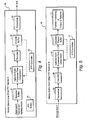
- Figure 4 is a function block diagram of a mobile station or other PTT sending device A
- Figure 5 is a function block diagram of a receiving mobile station or other PTT receiver B;
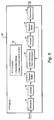
- FIG. 6 is a function block diagram illustrating a PTT server
- FIG. 7 is a flowchart that illustrates an example receiver-based compensation process
- FIG. 8 is a flowchart that illustrates an example sender-based compensation process
- FIG. 9 is a flowchart that illustrates an example PTT server-based compensation process
- Figure 10 illustrates a non-limiting example in which the receiver-based embodiment is employed
- Figure 11 illustrates a non-limiting example in which the sender-based embodiment is employed.
- Figure 12 is a non-limiting example in which the server-based embodiment is employed.
- FIG. 1 illustrates an example communications system 10 that supports PTT communications.
- a sending push-to-talk communications device 12 is coupled to a PTT server 14 which in turn is coupled to a PTT receiver device 16.
- the PTT communication may be set up and operated without a PTT server.
- the communications system 10 may be any type of communication system including those that support circuit-switched or packet-switched communications.
- the digital information exchanged can be speech, non-speech, or both.
- the PTT sending device 12 and the PTT receiving device 16 can be any type of communications device that supports PTT calls including any kind of wireless communications device, wireline telephones (e.g., used by a dispatcher), laptop computers, desktop computers, PDAs, etc.
- FIG. 2 is another, more detailed example in which a mobile radio communication system 20 supports push-to-talk communications involving one or more mobile radios.
- a core network represented as cloud 22, includes a push-to-talk server 24 in addition to one or more other nodes.
- Example core network nodes include a circuit-switched, core network node like a mobile switching center (MSC), a packet-switched node such as a gateway GPRS support node (GGSN) or a serving GPRS support node (SGSN), and a database node such as a home location register (HLR).
- the core network node(s) 22 is (are) coupled to a radio access network 26 which includes one or more radio network control (RNC) nodes 28.
- RNC radio network control
- Representative RNC nodes 28A and 28B are each coupled to one or more base stations 30. For simplicity only, each RNC is showed coupled to one base station 30A and 30B, respectively.
- Mobile radio terminals 32 communicate over a radio interface with one or more base stations 30. Two example mobile stations are shown, MS-A 32A and MS-B 32B.
- mobile station A as initiating a PTT communication with mobile station B.
- These mobile stations need not be served by the same core network, the same radio access network, the same RNC, the same base station, etc.
- the sender A and receiver B are not limited to mobile stations.
- the push-to-talk server (which may also support push-to-fax or push-to-some other communication medium or format) is preferably an instant messaging server that relays digital data between A and B. It may also perform other functions such as determining user device location, address, telephone number, etc. to establish a PTT communication between users A and B. For example, user A may not know user B's specific telephone number, IP address, or even where user B is located. User A simply depresses the PTT button on A's mobile station, identifies the name of B, and sends that PTT request to the PTT server. The PTT server translates B's name into B's IP address and/or B's mobile identifier (e.g., IMSI) in order to page or otherwise locate B. Once B is contacted, the PTT connection is set-up in the reverse direction from B to A to permit B's PTT response to A's initial message.
- IMSI mobile identifier
- step S1 A PTT connection is established between sender A and the PTT server, and after locating receiver B, a PTT connection is established between the PTT server and receiver B (step S2).
- the PTT connection establishment procedures require a set-up delay time before any of sender A's speech can be transmitted to receiver B. During that PTT set-up delay, sender A's speech is buffered (step S3).
- the set-up delay and any initial transmission/propagation delay from sender A to receiver B are compensated by reducing the time normally required for B to receive the initial message and play it out (step S4).
- a number of example, non-limiting compensations techniques are described below, but any compensation technique may be used.
- the main objective of a compensation technique is to reduce the "dead time" sender A must wait before receiving B's response to A's initial message. Time compression, increased transmission rates, faster buffer playout, frame dropping, and playout rate adjustment in packet headers are only examples. Whatever compensation technique(s) is (are) employed, implementation may employ electronic hardware, software-driven computers, or both.
- Figure 4 illustrates in function block form a mobile station A or other PTT sender A 40.
- the non-limiting example continues using speech as PTT content.
- Sender A initiates a PTT communication with receives B by pressing a PTT button 41 and starts speaking into a microphone (not shown).
- the detected speech is digitized and stored in a recorder buffer 42 while the PTT connection is being established.
- the buffered information is readout by an optional audio processor 44 which performs, in a first example embodiment, time compression of the buffered information before passing it on to encoder 46.
- the audio processor/time compressor 44 is indicated as optional because it may or may not be used depending on how and/or where the PTT set-up delay compensation is implemented.
- the encoder 46 encodes the time-compressed information and stores it in an encoder buffer 48.
- the encoded information is read out and transmitted by the transceiver 50 over the established PTT connection at a data transmission rate determined by the PTT controller 52.
- the time compression may be performed on encoded information by the encoder or other device.
- the PTT controller 52 controls the operation of the elements shown in Figure 4 and also performs various functions necessary to set-up, maintain, and break-down the PTT connection.
- a feedback link from the encoder buffer 48 to the audio processor 44 may be used to provide a basis for the time compression. In other words, the amount of data in the encoder buffer 48 dictates the amount of compression. If the amount of buffered data exceeds a threshold amount, time compression (or some alternative delay compensation technique) is employed.
- Figure 5 illustrates a function block diagram of the PTT receiver B 60.
- Speech from the sender A is received at a transceiver 62 and provided to a decoder 64, which outputs a digital information stream.
- An audio processor-time compressor 66 (optional depending on the embodiment) is employed in the second embodiment to time compress the digital information before storage in a decoder/playout buffer 68.
- the information readout from the buffer 68 is further processed at block 70 into a suitable analog signal and output at a speaker (not shown).
- the PTT controller 72 is involved in setting up the PTT connection with the PTT receiver 60 and also controls the audio processor/time compressor 66 and the playout buffer 68 in the second example embodiment.
- the positions of the audio processor 66 and decoder 64 can be exchanged and the time compression performed on the coded information.
- a feedback link from the playout buffer 68 to the audio processor 66 may be used to provide a basis for the time compression.
- the amount of data in the playout buffer 68 dictates the amount of compression. If the amount of buffered data exceeds a threshold amount, time compression (or some alternative delay compensation technique) is employed.
- Figure 6 illustrates in function block form a PTT server 80.
- Digital information is received from the sender A at a transceiver 81, decoded into digital information by decoder a 82, and stored in a decoder buffer 84.
- An (optional) audio processor-time compressor 86 is employed in the third example embodiment to time-compress the data retrieved from the decoder buffer 84.
- the encoder 88 encodes the time compressed data at a set coding rate and stores the encoded information in an encoder buffer 90. Encoded information from 90 is transmitted by a transceiver 92 at a prescribed link transmission rate to receiver B.
- the PTT controller 92 helps set-up the PTT connection and also controls the audio processor-time compressor 86, the encoder buffer 90 read in/readout, and the link transmission rate in the third example embodiment.
- the compression may be performed on the coded information without requiring the decoding and encoding.
- a feedback link from the encoder (or other) buffer 90 to the audio processor 86 may be used to provide a basis for the time compression. In other words, the amount of data in the buffer 90 dictates the amount of compression. If the amount of buffered data exceeds a threshold amount, time compression (or some alternative delay compensation technique) is employed.
- Figure 7 illustrates a receiver-based example embodiment for implementing time delay compensation. It may be implemented using hardware, software, or both.
- the push-to-talk controller 52 in the PTT receiver either determines (or receives from some other entity) a PTT set-up delay associated with setting up the PTT connection between A and B (step S1). For purposes of this example, the set-up delay is three seconds.
- the PTT controller 52 determines (or has provided to it) an increased link rate for transmitting the PTT information from A to the PTT server, a PTT sender buffer filling rate, and an amount buffered accumulated during the PTT set-up (step S2).
- the increased link rate is 24 kilobits per second (kbps)
- the sender buffer filling rate is 12 kbps
- the amount of buffered data accumulated during the PTT connection set-up is 36 kilobits (i.e., 12 kbps for three seconds).
- Speech packets/frames are transmitted from the PTT sender A at the increased link rate, which in this example, is 24 kbps (step S3).
- the packets arrive from sender A at the PTT server and are forwarded as soon as possible onto receiver B.
- specific link rates are identified in this and the following examples for illustration purposes, a best-effort bearer may be used along with whatever capacity becomes available to transmit the data queued up in the sender and/or the server.
- Receiver B receives speech packets/frames at the increased link rate (e.g., 24 kbps), decodes the speech packets into a digital audio stream, and time compresses the speech, which effectively increases the speech pitch (step S4).
- the time compression corresponds to a 25% increase in speech pitch which means that the speech can be readout 25% faster.
- the compressed speech data is stored in the decoder/playout buffer 68 (step S5).
- the PTT controller 72 controls the playout of the compressed speech in the playout buffer in the receiver at a faster rate than the rate at which the sender buffer was filled (step S6).
- a 25% pitch increase/time compression corresponds to an effective playout rate of 15 kbps.
- the playout rate is reduced to the sender encoding rate (step S7), which in this example is 12 kbps.
- the link transmission rate is reduced to its regular value, which for example may correspond to the sender encoding rate, e.g., 12 kbps.
- a second, non-limiting, example embodiment for implementing the set-up delay compensation is referred to as a sender-based compensation technique.
- the flowchart in Figure 8 illustrates example process steps for the sender-based compensation embodiment which may be implemented using hardware, software, or both.
- the PTT controller 52 in the PTT sender A determines (or has provided to it) the PTT connection set-up delay for establishing the PTT connection between A and B (step S1). Again, in this example, the set-up delay is three seconds.
- the PTT controller 52 determines an increase in speech pitch/frequency based on the determined set-up delay and from that determines how much time compression must be applied to the initial digital speech from A (step S2). As in the prior example, the time compression corresponds to a 25% increase in speech pitch.
- the audio processor-time compressor 44 time-compresses the speech in the recorder buffer 42 at a reduced code rate R1 (step S3). That reduced code rate R1, in this non-limiting example 9.6 kbps, reflects the 25% time compression.
- the time-compressed speech is then transmitted at a link rate R2 which is greater than the reduced coding rate R1 (step S4). In this non-limiting example, the link rate corresponds to 12 kbps.
- the speech frames are received and forwarded as soon as possible. The speech frames arrive and are played out at link rate R2.
- the time compression is halted, and uncompressed speech frames are played out at the link rate R2 (step S5).
- the third, non-limiting example, embodiment is referred to as the PTT server-based embodiment.
- the flowchart in Figure 9 illustrates example process steps for the PTT server-based compensation embodiment which may be implemented using hardware, software, or both.
- the PTT controller 92 determines (or has provided to it) the PTT connection set-up delay (step S1). As before, assume that this delay is three seconds.
- the PTT controller 92 also determines (or has provided to it) a coding rate, (e.g., 12 kbps), an increased link rate between sender A and the PTT server R1, (e.g. 24 kbps), and an amount of data stored in A's recorder buffer 42 during PTT set-up, (e.g., 36 kbit) (step S2).
- a coding rate e.g. 12 kbps
- an increased link rate between sender A and the PTT server R1 e.g. 24 kbps
- the buffered speech frames are transmit between A and the PTT server at the increased link rate R1, (e.g., 24 kbps) (step S3).
- the decoder 82 decodes the data from A and stores it in the decoder buffer 84 at the increased link rate R1, (e.g., 24 kbps) (step S4).
- the audio processor-time compressor 86 time compresses the buffered speech which increases the speech pitch (as in the prior examples by 25%).
- the encoder 88 encodes the time-compressed speech at a code rate R2 which is less than the increased link rate R1 (step S5). In this non-limiting example, that code rate R2 corresponds to 12 kbps.
- the encoder buffer 90 is filled with the time-compressed speech frames at the increased link rate R1, (e.g., 24 kbps), but is readout effectively at a lower, but still increased rate R3 (R2 ⁇ R3 ⁇ R1) (step S6).
- R3 corresponds to 15 kbps.
- the PTT server 92 ensures the speech frames are transmitted at the transceiver at a regular link rate corresponding to the coding rate R2, (e.g., 12 kbps) (step S7).
- the receiver B receives and buffers data in the playout buffer 68 at the regular link rate R2 (12 kbps) and plays it out at rate R2, which because of the time compression, is effectively a faster rate R3, (e.g., 15 kbps) (step S8).
- the transmission rate R1 (e.g., 24 kbps)
- R2 (e.g., 12 kbps)
- step S9 When the encoder buffer 90 in the PTT server 80 empties of A's initial message, the time compression performed by the audio processor 86 is halted, and further data are read into and played out of the playout buffer 68 in receiver B at the same rate.
- Figure 10 illustrates a time-line of a non-limiting, receiver-based example.
- the user A presses the PTT button to send a message to B and starts talking.
- A's buffer starts filling up with A's initial message M1 speech frames at a rate R1.
- the connection set-up delay corresponding to approximately 3 seconds in this example, occurs when the link between mobile A and the PTT server is being established.
- the initial message M1 is readout and transmission begins at 3 seconds at increased link rate R2.
- speech frames arrive from A at the PTT server, they are forwarded to B as soon as possible without buffering. They start arriving at B sometime after the three second connection set-up delay corresponding to a transmission/propagation delay time.
- the received speech frames are played out at a faster rate then they were recorded at A. For example, if the frames are readout of A at a rate R1 of 12 kbps but received at B at a rate R2 of 24 kbps, they can be readout at 15 kbps at mobile B. In other words, the data is played out 25% faster at B then it was recorded at A. This corresponds to an increase in pitch in the speech of 25% which is acceptable in speech and video communications.
- the recording buffer in mobile A is empty, so that the transmission rate is reduced from R1 to R2 (24 to 12 kbps).
- B will have received 72 kbits (3 seconds *24 kbps) and will have played out 45 kbits (three seconds *15 kbps).
- There are still 27 kbits in B's playout buffer which continue to be readout at the increased rate of 15kbps corresponding to a 25% increase in speech pitch. From this point on, B's playout buffer fills up at the code rate R1 corresponding to 12 kbps and drains at the higher effective playout rate of 15 kbps.
- B's playout buffer is essentially emptied.
- the new playout rate is reduced to the transmission rate R1 (e.g., 12 kbps) so that the filling and emptying of B's playout buffer is stabilized.
- R1 e.g. 12 kbps
- the A stops talking, signalling the ends of the first message M1.
- the last M1 message frames arrive at mobile B and are played out.
- the user at mobile B responds with message M2 which is sent out the normal transmit rate, in this example 12 kbps, and is played out at mobile A after the transmission delay at the same rate.
- a time-line of a non-limiting, sender-based example is shown in Figure 11 .
- the A presses the PTT button which initates establishment of a PTT connection via the PTT server with the mobile B.
- the recording buffer in mobile A starts capturing digital audio for the initial message M1 from A.
- the audio processor 44 in mobile A begins time-compressing that speech (in this non-limiting example 1.25 seconds are compressed to fit into one second corresponding to an increase in pitch of 25%).
- the PTT connection has been set-up, and the time-compressed data is sent out at the link rate, (e.g., 12 kbps).
- the encoder buffer 48 in mobile A contains three seconds of original speech, which when time-compressed, corresponds to 2.4 seconds of compressed speech (2.4 seconds *12 kbps equals 28.8 kbits). Effectively in this example, the speech data is stored in the encoder buffer 48 at code rate 9.6 kbps, and the packets are output at a code rate of 12 kbps. The data is forwarded by the PTT server without delay or buffering. At three seconds plus the transmission delay, the speech frames arrive at B at 12 kbps and are played out at the same rate. At time 15 seconds, the encoder buffer 48 is emptied, and the PTT controller halts the time compression being performed by the audio processor 44. At 15 seconds plus the transmission delay, B receives the frames at the normal rate without compression.
- a time-line of a non-limiting example of the server-based embodiment is illustrated in Figure 12 .
- the user of mobile A presses the PTT button, and a PTT connection is initiated between A and B via the PTT server.
- A's recording buffer 42 starts filling with speech frames corresponding to the initial message M1.
- the buffered speech is encoded and stored in the encoding buffer 48 at a standard encoding rate R1 (for example 12 kbps).
- R1 for example 12 kbps
- the PTT connection has been established, and data is readout from the encoding buffer at an increased link rate R2.
- the rate R2 e.g., 24 kbps
- the rate R2 is twice as fast as the rate R1 in which the encoder buffer is filled.
- the encoder buffer 48 there are 36 kbits (12 kbps* three seconds) stored in the encoder buffer 48.
- the initial speech packets are forwarded to the decoder buffer 84 at the increased rate R2.
- the audio processor 86 time-compresses the speech from the decoder buffer 84.
- the time-compressed speech is then encoded and stored in the encoder buffer 90.
- the encoder buffer fills at R2 (e.g., 24 kbps) and drains at effectively R3 (R2>R3>R1) (e.g., 15 kbps) and is transmitted at the normal link rate R1 to mobile B.
- Mobile B receives that information shortly thereafter and plays it out at that received link rate R1.
- the effective receiving rate corresponds to R3 (e.g., 15 kbps), so the playout from B's playout buffer 68 at the normal link rate R1 (e.g., 12 kbps) effectively occurs at a higher rate of R3 (e.g., 15 kbps).
- R3 e.g. 15 kbps
- the encoder buffer in mobile A empties/stabilizes, (there is no backlog), and the transmission rate from A to the PTT server is decreased to the code rate R1.
- 72 kbits have been received at the PTT server, (3 seconds *24 kbps), and 45 kbps have been played out so far, (3 seconds *15 kbps).
- 27 kbits remain in the encoder buffer 90 which continues to fill up at R1 (e.g., 12 kbps) and drain at R3 (e.g., 15 kbps).
- the mobile B receives the data at R1 (e.g., 12 kbps) and plays it out effectively at R3 (e.g., 15 kbps).
- R1 e.g., 12 kbps
- R3 e.g. 15 kbps
- the encoder buffer 90 is empty.
- the time compression performed by the audio processor 86 is halted.
- the code rates are matched up to provide steady, stable operation.
- delay compensation may be based on buffer fill states. If the buffered data exceeds a threshold, playout is increased at the receiver. In other words, playout rate depends on the amount of data currently in the buffer. The flexibility of this compensation approach is particularly advantageous when the setup or other delays are not known or are not constant.
- Another example compensation technique for packetized information that specifies a playout rate in the packet header is to increase the playout rate in each packet's header until any delay is compensated.
- Real Time Protocol (RTP) headers use for transporting video are an example of packet headers that specify playout rates. This approach is advantageous because the packet content is not affected.
Landscapes
- Engineering & Computer Science (AREA)
- Computer Networks & Wireless Communication (AREA)
- Signal Processing (AREA)
- Multimedia (AREA)
- Business, Economics & Management (AREA)
- General Business, Economics & Management (AREA)
- Telephonic Communication Services (AREA)
- Mobile Radio Communication Systems (AREA)
- Data Exchanges In Wide-Area Networks (AREA)
Description
- The technical field relates to real time interactive services, such as a push-to-talk (PTT) service, in a digital radio communications system.
- Push-to-talk (PTT) is a service where users may be connected in either a one-to-one radio communication or in a group radio communication. PTT service has traditionally been used in applications where one person, a "dispatcher" needs to a communicate to a group of people, such as field service personnel like taxi drivers, which is where the "dispatch" name for the service comes from. The PTT functionality is similar to analog walkie-talkies where the users take turns in talking. A user simply presses a button to start transmitting.
- Nextel describes its PTT service "Direct Connect" as a "digital, long-range walkie-talkie" built into a wireless handset which lets it "connect" to a similarly configured handset without the need for standard cellular telephone "connect" procedures, such as dialing a telephone number and generating a ringing signal. The conversation exchange is managed as a half-duplex session that allows only one party to talk at a time. Various controls are used to avoid collisions when users transmit at the same time. For example, modem PTT communications often occur via a server, which responds to PTT requests by granting (or denying) a "floor," i.e., permission to transmit.
- A PTT conversation may be communicated over standard, circuit-switched networks as well as over packet-switched, Internet Protocol (IP) networks. Indeed, PTT-type services have been offered on the Internet and are generally known as "voice chat." These services are usually implemented as personnel computer applications that send vocoder frames in IP packets, i.e., a voice-over-IP (VoIP) service, to a central group chat server, or possibly from client-to-client in a peer-to-peer service.
- Push-to-talk calis are desirable because they use bandwidth efficiently-an important benefit in radio communications where radio bandwidth is a scarce and expensive resource. They also permit group calls as easily as one-to-one calls. Another key advantage of PTT services is that the communication is quick and spontaneous, initiated by simply pressing the PTT button, without a going through typical dialing and ringing sequences.
- The patent application
EP 1182895A1 present a method and apparatus for performing a voice dispatch call in a digital communication system. A dispatch group that includes a plurality of communication units is established at a dispatch server. - Unfortunately, set-up times and propagation delays in PTT communications diminish the interactive "feel" when the push-to-talk communication is two-way, e.g., A and B are having a conversation. The set-up time for a digital PTT call may take two to three seconds. An example initial PTT request-response cycle might look as follows:
- At zero seconds, user A pushes a button to initiate a PTT conversation with user B and talks for ten seconds.
- At three seconds, the set-up is finished, and user B starts playing out the information sent by A.
- At thirteen seconds, the initial message from A is completely played out by B. At that very same moment, (assuming that B has extremely quick reactions). 13 pushes its PTT button to respond and talks for three seconds.
- Sometime after sixteen seconds. (there are transfer delays in the system). A starts playing out B's response message.
- The present invention improves the interactive feel of and reduces delays associated with PTT and other real time, interactive communication exchanges. One example of another real-time, interactive communication is an interactive video communication. But for ease of description hereafter, a PTT speech service is employed as a non-limiting example of a real time, interactive communication exchange. A first communications device user initiates a PTT communication with a second communication device, e.g., by pressing a PTT button. At the time of initiation, the first device user provides initial digital content for transmission to the second device. In response to the PTT communication initiation, a set-up procedure begins to establish a PTT connection between the first and second devices. The delay time associated with establishing the PTT connection is compensated for so that the second device user receives the initial digital content and can respond faster than it could without the delay time compensation. A faster response by the second device user reduces the undesirable response delay time between when the first user stops talking and the second user's response is received. That shorter response time enhances the interactive, real-time, conversational feel of the PTT communication between the first and second users.
- The delay time includes delays associated with setting up the PTT connection and the propagation time associated with sending the initial digital content from the first device to the second device. Although particularly well-suited to voice communications, the digital content may also be or include non-voice content as well, e.g., video. The communication devices may be for example mobile or stationary wireless devices including handsets, laptops, PDAs, etc. The PTT service may be supported in a circuit-switched network or a packet-switched network.
- The delay compensation may be accomplished in a variety ways. In one non-limiting example, the initial digital content is time-compressed which effectively speeds up the playout of the initial digital content at the second device. In other words, if the initial digital content is a ten-second voice message, that voice message may be time-compressed so that it is played out in only seven seconds with a higher pitch/frequency. Such time compression may occur at the first device, second device, or at a PTT server involved in the PTT communications.
- The delay compensation may include increasing the rate at which the digital content is transmitted over the PTT connection. As a result, the transmission rate is faster than the real-time rate at which the initial digital content is buffered in the first device. The result again is that the received data can be played out faster than real-time, thus reducing the time the sender must wait for the receiver's response.
- For purposes of illustration, three, non-limiting, example PTT communication embodiments are described. A first example embodiment is implemented in a first sending radio A. A second example embodiment is implemented in a second receiving mobile radio B. And a third example embodiment is implemented using a PTT server. Details of those non-limiting, example embodiments are set forth below. Although those embodiments that time compress uncoded information, the time compression may also be performed on coded information.
- In addition to improving interactivity, the compensation does not require knowledge of communication setup and transfer delays. Implementation requires changes only on the application level, which minimizes its impact and facilitates its introduction in existing communications systems. Moreover, if compression is performed at the sender or in the server, the data volume that the connection to the receiver must convey is reduced.
- Other delay compensation approaches and mechanisms for implementing them may be employed. For example, delay compensation may be based on buffer fill states. If the buffered data exceeds a threshold, playout rate is increased at the receiver. In other words, playout rate depends on the amount of data currently in the buffer. The flexibility of this compensation approach is particularly advantageous when the setup or other delays are not known or are not constant. Another example compensation technique for packetized information that specifies a playout rate in the packet header is to increase the playout rate in each packet's header until any delay is compensated. Real Time Protocol (RTP) headers use for transporting video are an example of packet headers that specify playout rates. This approach is advantageous because the packet content is not affected.
-
Figure 1 illustrates a push-to-talk communication system; -
Figure 2 illustrates a mobile radio system that supports a push-to-talk communications service; -
Figure 3 is a flowchart that illustrates an example process for compensating for initial set-up delays for a push-to-talk communications; -
Figure 4 is a function block diagram of a mobile station or other PTT sending device A; -
Figure 5 is a function block diagram of a receiving mobile station or other PTT receiver B; -
Figure 6 is a function block diagram illustrating a PTT server; -
Figure 7 is a flowchart that illustrates an example receiver-based compensation process; -
Figure 8 is a flowchart that illustrates an example sender-based compensation process; -
Figure 9 is a flowchart that illustrates an example PTT server-based compensation process; -
Figure 10 illustrates a non-limiting example in which the receiver-based embodiment is employed; -
Figure 11 illustrates a non-limiting example in which the sender-based embodiment is employed; and -
Figure 12 is a non-limiting example in which the server-based embodiment is employed. - For purposes of explanation, and not limitation, the following description sets forth specific details, such as particular electronic circuitry, procedures, techniques, etc., in order to provide an understanding of the present invention. In other instances, detailed descriptions of well-known methods, devices, and techniques, etc., are omitted so as not to obscure the description with unnecessary detail. For example, a PTT service is used below as an example real-time, interactive application. But the invention may be employed in real time, interactive communications other than PTT communications. Individual function blocks are shown in one or more figures. Those skilled in the art will appreciate that one or more function blocks may be implemented using discrete components, multi-function hardware, a suitably-programmed computer or microprocessor, application specific integrated circuitry, etc. or any combination thereof. Also, it is understood that the terminology used herein is for the purpose of description and should not be regarded as limiting.
-
Figure 1 illustrates anexample communications system 10 that supports PTT communications. A sending push-to-talk communications device 12 is coupled to aPTT server 14 which in turn is coupled to aPTT receiver device 16. Alternatively, the PTT communication may be set up and operated without a PTT server. Thecommunications system 10 may be any type of communication system including those that support circuit-switched or packet-switched communications. The digital information exchanged can be speech, non-speech, or both. ThePTT sending device 12 and thePTT receiving device 16 can be any type of communications device that supports PTT calls including any kind of wireless communications device, wireline telephones (e.g., used by a dispatcher), laptop computers, desktop computers, PDAs, etc. -
Figure 2 is another, more detailed example in which a mobileradio communication system 20 supports push-to-talk communications involving one or more mobile radios. A core network, represented ascloud 22, includes a push-to-talk server 24 in addition to one or more other nodes. Example core network nodes include a circuit-switched, core network node like a mobile switching center (MSC), a packet-switched node such as a gateway GPRS support node (GGSN) or a serving GPRS support node (SGSN), and a database node such as a home location register (HLR). The core network node(s) 22 is (are) coupled to aradio access network 26 which includes one or more radio network control (RNC) nodes 28.Representative RNC nodes base station A 32A and MS-B 32B. - Subsequent examples describe mobile station A as initiating a PTT communication with mobile station B. These mobile stations need not be served by the same core network, the same radio access network, the same RNC, the same base station, etc. Again, the sender A and receiver B are not limited to mobile stations.
- The push-to-talk server (which may also support push-to-fax or push-to-some other communication medium or format) is preferably an instant messaging server that relays digital data between A and B. It may also perform other functions such as determining user device location, address, telephone number, etc. to establish a PTT communication between users A and B. For example, user A may not know user B's specific telephone number, IP address, or even where user B is located. User A simply depresses the PTT button on A's mobile station, identifies the name of B, and sends that PTT request to the PTT server. The PTT server translates B's name into B's IP address and/or B's mobile identifier (e.g., IMSI) in order to page or otherwise locate B. Once B is contacted, the PTT connection is set-up in the reverse direction from B to A to permit B's PTT response to A's initial message.
- Reference is made to the flowchart in
Figure 3 illustrating certain steps performed an example PTT voice communication in which initial PTT connection set-up delays are compensated for. The sender A presses a PTT button having identified the receiver B and starts talking (step S1). A PTT connection is established between sender A and the PTT server, and after locating receiver B, a PTT connection is established between the PTT server and receiver B (step S2). The PTT connection establishment procedures require a set-up delay time before any of sender A's speech can be transmitted to receiver B. During that PTT set-up delay, sender A's speech is buffered (step S3). The set-up delay and any initial transmission/propagation delay from sender A to receiver B are compensated by reducing the time normally required for B to receive the initial message and play it out (step S4). A number of example, non-limiting compensations techniques are described below, but any compensation technique may be used. The main objective of a compensation technique is to reduce the "dead time" sender A must wait before receiving B's response to A's initial message. Time compression, increased transmission rates, faster buffer playout, frame dropping, and playout rate adjustment in packet headers are only examples. Whatever compensation technique(s) is (are) employed, implementation may employ electronic hardware, software-driven computers, or both. -
Figure 4 illustrates in function block form a mobile station A or otherPTT sender A 40. The non-limiting example continues using speech as PTT content. Sender A initiates a PTT communication with receives B by pressing aPTT button 41 and starts speaking into a microphone (not shown). The detected speech is digitized and stored in arecorder buffer 42 while the PTT connection is being established. Once the PTT connection is established, the buffered information is readout by anoptional audio processor 44 which performs, in a first example embodiment, time compression of the buffered information before passing it on toencoder 46. The audio processor/time compressor 44 is indicated as optional because it may or may not be used depending on how and/or where the PTT set-up delay compensation is implemented. Theencoder 46 encodes the time-compressed information and stores it in anencoder buffer 48. The encoded information is read out and transmitted by thetransceiver 50 over the established PTT connection at a data transmission rate determined by thePTT controller 52. Alternatively, the time compression may be performed on encoded information by the encoder or other device. ThePTT controller 52 controls the operation of the elements shown inFigure 4 and also performs various functions necessary to set-up, maintain, and break-down the PTT connection. As another alternative, a feedback link from theencoder buffer 48 to theaudio processor 44 may be used to provide a basis for the time compression. In other words, the amount of data in theencoder buffer 48 dictates the amount of compression. If the amount of buffered data exceeds a threshold amount, time compression (or some alternative delay compensation technique) is employed. -
Figure 5 illustrates a function block diagram of thePTT receiver B 60. Speech from the sender A is received at atransceiver 62 and provided to adecoder 64, which outputs a digital information stream. An audio processor-time compressor 66 (optional depending on the embodiment) is employed in the second embodiment to time compress the digital information before storage in a decoder/playout buffer 68. The information readout from thebuffer 68 is further processed atblock 70 into a suitable analog signal and output at a speaker (not shown). ThePTT controller 72 is involved in setting up the PTT connection with thePTT receiver 60 and also controls the audio processor/time compressor 66 and theplayout buffer 68 in the second example embodiment. Alternatively, the positions of theaudio processor 66 anddecoder 64 can be exchanged and the time compression performed on the coded information. As another alternative, a feedback link from theplayout buffer 68 to theaudio processor 66 may be used to provide a basis for the time compression. In other words, the amount of data in theplayout buffer 68 dictates the amount of compression. If the amount of buffered data exceeds a threshold amount, time compression (or some alternative delay compensation technique) is employed. -
Figure 6 illustrates in function block form aPTT server 80. Digital information is received from the sender A at atransceiver 81, decoded into digital information by decoder a 82, and stored in adecoder buffer 84. An (optional) audio processor-time compressor 86 is employed in the third example embodiment to time-compress the data retrieved from thedecoder buffer 84. Theencoder 88 encodes the time compressed data at a set coding rate and stores the encoded information in anencoder buffer 90. Encoded information from 90 is transmitted by atransceiver 92 at a prescribed link transmission rate to receiver B. ThePTT controller 92 helps set-up the PTT connection and also controls the audio processor-time compressor 86, theencoder buffer 90 read in/readout, and the link transmission rate in the third example embodiment.
Alternatively, the compression may be performed on the coded information without requiring the decoding and encoding. As another alternative, a feedback link from the encoder (or other) buffer 90 to theaudio processor 86 may be used to provide a basis for the time compression. In other words, the amount of data in thebuffer 90 dictates the amount of compression. If the amount of buffered data exceeds a threshold amount, time compression (or some alternative delay compensation technique) is employed. -
Figure 7 illustrates a receiver-based example embodiment for implementing time delay compensation. It may be implemented using hardware, software, or both. The push-to-talk controller 52 in the PTT receiver either determines (or receives from some other entity) a PTT set-up delay associated with setting up the PTT connection between A and B (step S1). For purposes of this example, the set-up delay is three seconds. ThePTT controller 52 determines (or has provided to it) an increased link rate for transmitting the PTT information from A to the PTT server, a PTT sender buffer filling rate, and an amount buffered accumulated during the PTT set-up (step S2). In this non-limiting example, the increased link rate is 24 kilobits per second (kbps), the sender buffer filling rate is 12 kbps, and the amount of buffered data accumulated during the PTT connection set-up is 36 kilobits (i.e., 12 kbps for three seconds). Speech packets/frames are transmitted from the PTT sender A at the increased link rate, which in this example, is 24 kbps (step S3). The packets arrive from sender A at the PTT server and are forwarded as soon as possible onto receiver B. Although specific link rates are identified in this and the following examples for illustration purposes, a best-effort bearer may be used along with whatever capacity becomes available to transmit the data queued up in the sender and/or the server. - Receiver B receives speech packets/frames at the increased link rate (e.g., 24 kbps), decodes the speech packets into a digital audio stream, and time compresses the speech, which effectively increases the speech pitch (step S4). In this non-limiting example, the time compression corresponds to a 25% increase in speech pitch which means that the speech can be readout 25% faster. The compressed speech data is stored in the decoder/playout buffer 68 (step S5). The
PTT controller 72 controls the playout of the compressed speech in the playout buffer in the receiver at a faster rate than the rate at which the sender buffer was filled (step S6). In this non-limiting example, a 25% pitch increase/time compression corresponds to an effective playout rate of 15 kbps. When theplayout buffer 68 is emptied of A's initial message information, the playout rate is reduced to the sender encoding rate (step S7), which in this example is 12 kbps. Moreover, the link transmission rate is reduced to its regular value, which for example may correspond to the sender encoding rate, e.g., 12 kbps. - A second, non-limiting, example embodiment for implementing the set-up delay compensation is referred to as a sender-based compensation technique. The flowchart in
Figure 8 illustrates example process steps for the sender-based compensation embodiment which may be implemented using hardware, software, or both. ThePTT controller 52 in the PTT sender A determines (or has provided to it) the PTT connection set-up delay for establishing the PTT connection between A and B (step S1). Again, in this example, the set-up delay is three seconds. ThePTT controller 52 determines an increase in speech pitch/frequency based on the determined set-up delay and from that determines how much time compression must be applied to the initial digital speech from A (step S2). As in the prior example, the time compression corresponds to a 25% increase in speech pitch. After depressing thePTT button 41 and storing the initial message content in therecorder buffer 42, the audio processor-time compressor 44 time-compresses the speech in therecorder buffer 42 at a reduced code rate R1 (step S3). That reduced code rate R1, in this non-limiting example 9.6 kbps, reflects the 25% time compression. The time-compressed speech is then transmitted at a link rate R2 which is greater than the reduced coding rate R1 (step S4). In this non-limiting example, the link rate corresponds to 12 kbps. At the PTT server, the speech frames are received and forwarded as soon as possible. The speech frames arrive and are played out at link rate R2. When A's buffer is emptied of the initial message, the time compression is halted, and uncompressed speech frames are played out at the link rate R2 (step S5). - The third, non-limiting example, embodiment is referred to as the PTT server-based embodiment. The flowchart in
Figure 9 illustrates example process steps for the PTT server-based compensation embodiment which may be implemented using hardware, software, or both. ThePTT controller 92 determines (or has provided to it) the PTT connection set-up delay (step S1). As before, assume that this delay is three seconds. ThePTT controller 92 also determines (or has provided to it) a coding rate, (e.g., 12 kbps), an increased link rate between sender A and the PTT server R1, (e.g. 24 kbps), and an amount of data stored in A'srecorder buffer 42 during PTT set-up, (e.g., 36 kbit) (step S2). The buffered speech frames are transmit between A and the PTT server at the increased link rate R1, (e.g., 24 kbps) (step S3). Thedecoder 82 decodes the data from A and stores it in thedecoder buffer 84 at the increased link rate R1, (e.g., 24 kbps) (step S4). The audio processor-time compressor 86 time compresses the buffered speech which increases the speech pitch (as in the prior examples by 25%). Theencoder 88 encodes the time-compressed speech at a code rate R2 which is less than the increased link rate R1 (step S5). In this non-limiting example, that code rate R2 corresponds to 12 kbps. Theencoder buffer 90 is filled with the time-compressed speech frames at the increased link rate R1, (e.g., 24 kbps), but is readout effectively at a lower, but still increased rate R3 (R2 < R3 < R1) (step S6). In this non-limiting example, R3 corresponds to 15 kbps. ThePTT server 92 ensures the speech frames are transmitted at the transceiver at a regular link rate corresponding to the coding rate R2, (e.g., 12 kbps) (step S7). The receiver B receives and buffers data in theplayout buffer 68 at the regular link rate R2 (12 kbps) and plays it out at rate R2, which because of the time compression, is effectively a faster rate R3, (e.g., 15 kbps) (step S8). When the initial message content in A has been completely transmitted by A, the transmission rate R1, (e.g., 24 kbps), is returned to the regular transmission rate R2, (e.g., 12 kbps) (step S9). When theencoder buffer 90 in thePTT server 80 empties of A's initial message, the time compression performed by theaudio processor 86 is halted, and further data are read into and played out of theplayout buffer 68 in receiver B at the same rate. -
Figure 10 illustrates a time-line of a non-limiting, receiver-based example. At zero seconds, the user A presses the PTT button to send a message to B and starts talking. A's buffer starts filling up with A's initial message M1 speech frames at a rate R1. The connection set-up delay, corresponding to approximately 3 seconds in this example, occurs when the link between mobile A and the PTT server is being established. The initial message M1 is readout and transmission begins at 3 seconds at increased link rate R2. As speech frames arrive from A at the PTT server, they are forwarded to B as soon as possible without buffering. They start arriving at B sometime after the three second connection set-up delay corresponding to a transmission/propagation delay time. The received speech frames are played out at a faster rate then they were recorded at A. For example, if the frames are readout of A at a rate R1 of 12 kbps but received at B at a rate R2 of 24 kbps, they can be readout at 15 kbps at mobile B. In other words, the data is played out 25% faster at B then it was recorded at A. This corresponds to an increase in pitch in the speech of 25% which is acceptable in speech and video communications. - At 6 seconds, the recording buffer in mobile A is empty, so that the transmission rate is reduced from R1 to R2 (24 to 12 kbps). At a time of six seconds plus the transmission delay, B will have received 72 kbits (3 seconds *24 kbps) and will have played out 45 kbits (three seconds *15 kbps). There are still 27 kbits in B's playout buffer which continue to be readout at the increased rate of 15kbps corresponding to a 25% increase in speech pitch. From this point on, B's playout buffer fills up at the code rate R1 corresponding to 12 kbps and drains at the higher effective playout rate of 15 kbps. At 15 seconds plus the transmission delay, B's playout buffer is essentially emptied. (In a practical application, one would likely leave a certain amount of data in the buffer to compensate for rate/delay variations, especially if a packet-switched transmission scheme is used). The new playout rate is reduced to the transmission rate R1 (e.g., 12 kbps) so that the filling and emptying of B's playout buffer is stabilized. At 20 seconds, the A stops talking, signalling the ends of the first message M1. At
time 20 seconds plus the transmission delay, the last M1 message frames arrive at mobile B and are played out. Attime 21 seconds, the user at mobile B responds with message M2 which is sent out the normal transmit rate, in this example 12 kbps, and is played out at mobile A after the transmission delay at the same rate. - A time-line of a non-limiting, sender-based example is shown in
Figure 11 . At zero seconds, the A presses the PTT button which initates establishment of a PTT connection via the PTT server with the mobile B. At the same time, the recording buffer in mobile A starts capturing digital audio for the initial message M1 from A. At 1.25 seconds, theaudio processor 44 in mobile A begins time-compressing that speech (in this non-limiting example 1.25 seconds are compressed to fit into one second corresponding to an increase in pitch of 25%). At three seconds, the PTT connection has been set-up, and the time-compressed data is sent out at the link rate, (e.g., 12 kbps). Theencoder buffer 48 in mobile A contains three seconds of original speech, which when time-compressed, corresponds to 2.4 seconds of compressed speech (2.4 seconds *12 kbps equals 28.8 kbits). Effectively in this example, the speech data is stored in theencoder buffer 48 at code rate 9.6 kbps, and the packets are output at a code rate of 12 kbps. The data is forwarded by the PTT server without delay or buffering. At three seconds plus the transmission delay, the speech frames arrive at B at 12 kbps and are played out at the same rate. Attime 15 seconds, theencoder buffer 48 is emptied, and the PTT controller halts the time compression being performed by theaudio processor 44. At 15 seconds plus the transmission delay, B receives the frames at the normal rate without compression. - A time-line of a non-limiting example of the server-based embodiment is illustrated in
Figure 12 . At zero seconds, the user of mobile A presses the PTT button, and a PTT connection is initiated between A and B via the PTT server. A'srecording buffer 42 starts filling with speech frames corresponding to the initial message M1. The buffered speech is encoded and stored in theencoding buffer 48 at a standard encoding rate R1 (for example 12 kbps). At three seconds, the PTT connection has been established, and data is readout from the encoding buffer at an increased link rate R2. In this example, the rate R2 (e.g., 24 kbps) is twice as fast as the rate R1 in which the encoder buffer is filled. Accordingly, at three seconds, there are 36 kbits (12 kbps* three seconds) stored in theencoder buffer 48. At three seconds plus a transmission delay, the initial speech packets are forwarded to thedecoder buffer 84 at the increased rate R2. Theaudio processor 86 time-compresses the speech from thedecoder buffer 84. The time-compressed speech is then encoded and stored in theencoder buffer 90. The encoder buffer fills at R2 (e.g., 24 kbps) and drains at effectively R3 (R2>R3>R1) (e.g., 15 kbps) and is transmitted at the normal link rate R1 to mobile B. Mobile B receives that information shortly thereafter and plays it out at that received link rate R1. Because of the time compression, the effective receiving rate corresponds to R3 (e.g., 15 kbps), so the playout from B'splayout buffer 68 at the normal link rate R1 (e.g., 12 kbps) effectively occurs at a higher rate of R3 (e.g., 15 kbps). At six seconds, the encoder buffer in mobile A empties/stabilizes, (there is no backlog), and the transmission rate from A to the PTT server is decreased to the code rate R1. Shortly thereafter, 72 kbits have been received at the PTT server, (3 seconds *24 kbps), and 45 kbps have been played out so far, (3 seconds *15 kbps). 27 kbits remain in theencoder buffer 90 which continues to fill up at R1 (e.g., 12 kbps) and drain at R3 (e.g., 15 kbps). The mobile B receives the data at R1 (e.g., 12 kbps) and plays it out effectively at R3 (e.g., 15 kbps). At 15 seconds plus a short transmission delay, theencoder buffer 90 is empty. The time compression performed by theaudio processor 86 is halted. The code rates are matched up to provide steady, stable operation. - Other delay compensation approaches and mechanisms for implementing them may be employed. For example, delay compensation may be based on buffer fill states. If the buffered data exceeds a threshold, playout is increased at the receiver. In other words, playout rate depends on the amount of data currently in the buffer. The flexibility of this compensation approach is particularly advantageous when the setup or other delays are not known or are not constant. Another example compensation technique for packetized information that specifies a playout rate in the packet header is to increase the playout rate in each packet's header until any delay is compensated. Real Time Protocol (RTP) headers use for transporting video are an example of packet headers that specify playout rates. This approach is advantageous because the packet content is not affected.
- Several example embodiments have been described. But the invention is not limited to the disclosed embodiments. Any delay compensation technique may be used, and it can be implemented in any one or more nodes that affect a real time, interactive communication. The invention is applicable to any real time, interactive communication service and is not limited to PTT services or to first-time, initial communications. The invention is intended to cover various modifications and equivalent arrangements included within the scope of the appended claims.
Claims (42)
- A method to improve real time interactive communication using a push-to-talk service in a communications system (10), the method comprising establishment of a real-time, interactive connection between a first sending communications terminal (12) and a second receiving communications terminal (16), and transmission of initial digital information on the connection, the connection establishment requiring a set-up time , characterized by compensating for a delay time associated with establishing the real-time, interactive connection by playing out the initial digital content at an increased rate at the second receiving terminal (16).
- The method in claim 1, characterized in that at least one of the first and second communications terminals (12, 16) are mobile radio terminals (32).
- The method in claim 2, characterized in that the delay time includes further to the connection set-up time a propagation time associated with sending the digital content information from the sending communications device (12) to the second receiving communications terminal (16).
- The method in claim 1, characterized in that the digital content information corresponds to speech information or non-speech information.
- The method in claim 1, characterized in that the increased play out time at the second receiving communications terminal (16) is achieved by time-compressing the initial digital content information until the delay time is compensated for.
- The method in claim 5, characterized in that the increased play out time at the second receiving communications terminal (16) is achieved by determining an amount of information stored in a buffer (48) waiting to be communicated to the second receiving communications terminal (16), and controlling the rate at which the initial digital information content is played out of the buffer based on the determined amount.
- The method in claim 5, characterized in that the time compression occurs at the first sending communications terminal (12).
- The method in claim 5, characterized in that the time compression occurs at the second receiving communications terminal (16).
- The method in claim 1, characterized in that the real-time, interactive communication is established using a server (14), and wherein the server (14) is involved in the compensating.
- The method in claim 1, characterized by buffering the initial digital information, and temporarily increasing a transmission rate of the buffered initial digital information so that the initial digital information is transmitted over the established real-time, interactive connection faster than the initial digital content information is buffered.
- The method in claim 1, characterized in that the real-time, interactive connection is a push-to-talk connection and the digital information corresponds to speech information.
- The method in claim 1 characterized in that the real-time, interactive communication is an interactive video communication.
- The method in claim 1, characterized in that the digital information corresponds to packets each having a packet header including a play-out indicator, and wherein the increased play out time at the second receiving communications terminal (16) is achieved by modifying the play-out indicator in the packets to change the rate at which the packets are played out.
- The method in claim 1, characterized in that the increased rate at the second receiving communication terminal (16) is achieved by determining an amount of information stored in a buffer (48) waiting to be communicated to the second receiving communications terminal, and controlling the rate at which the information is played out of the buffer (48) based on the determined amount.
- A first terminal (12) for use in a communications system (10) that supports real-time, interactive communications using a push-to-talk service, comprising:an actuator (41) actuable by a first user to engage in a real-time, interactive communication between the first terminal (12) and a second terminal (16);a buffer (42) for storing digital content information from the first user to be sent to the second terminal (16); andtransceiving circuitry (50) for transmitting a request to establish a real-time, interactive connection between the first terminal and the second terminal, and for transmitting initial digital information on the connection, the connection establishment requiring a set-up time, characterized by delay compensation means (42, 44, 52) adapted to increase, at the second terminal, the play out rate of the initial information so as to compensate for a delay time associated with establishing the real-time interactive connection.
- A first terminal in accordance with claim 15 characterized in that the delay compensation means comprise a time compressor (44) for time-compressing the buffered initial digital content information to compensate for the time delay and for supplying the time-compressed initial information to the transceiving circuitry (50) for transmission to the second device over the real-time, interactive connection.
- The first terminal in claim 16, characterized by an encoder (46) for coding the time-compressed information at an effective first rate that is less than a second rate at which the coded information is transmitted by the radio transceiving circuitry (50).
- The first terminal in claim 15, characterized in that the delay compensation means (44, 52) are configured to control the transceiving circuitry (50) to transmit the digital content at a temporarily-increased transmission rate.
- The first terminal in claim 15, characterized by a controller for determining a time delay associated with the establishing the real-time interactive connection, the controller (50) being configured to halt operation of the delay compensation means ( 44, 52) when the time delay has been compensated for.
- The first terminal in claim 15, characterized in that the real-time, interactive connection is a push-to-talk connection and the digital content information corresponds to speech information.
- The first terminal in claim 15, characterized in that the real-time, interactive communication is an interactive video communication.
- The first terminal in claim 15, characterized in that the digital information corresponds to packets each having a packet header including a playout indicator, and wherein the delay compensation means are configured to modify the playout indicator in the packets to change a rate at which the packets are played out.
- The first terminal in claim 15, characterized in that the delay compensation means (44, 52) are configured to determine an amount of information stored in the buffer (46) waiting to be communicated to the second terminal user and to control a rate at which the initial digital information is played out of the buffer (46) based on the determined amount.
- A second terminal (16) for use in a communications system (10) that supports a real-time, interactive communication service using a push-to-talk service, the communication taking place between a first terminal (12) and the second terminal (16), the second terminal (16) comprising:transceiving circuitry (62) for receiving initial digital content information from the first terminal (12) at a first rate over a real-time, interactive connection established between the first terminal (12) and the second terminal (16), the second terminal further comprising:a buffer (68) for storing the digital information from the first terminal (12) at the first rate and presenting the buffered information to a user of the second terminal (16),
characterized by:delay compensation means (66, 72) adapted to increase, at the second terminal, the play out rate of the initial digital information so as to compensate for a delay time associated with establishing the real-time, interactive connection. - The second terminal in claim 24, characterized in that the delay compensation means (66, 72) include a time compressor (66) for time-compressing the initial digital information to compensate for the determined time delay and for supplying the time-compressed information for storage in the buffer (68), and
wherein the compressed information stored in the buffer (68) is retrieved from the buffer (68) at a second rate less than the first rate. - The second terminal in claim 25, characterized in that when the initial digital information is transmitted from the first terminal (12), the transceiving circuitry (62) is configured to receive subsequent digital content information from the first terminal (12) at a third rate less than the first rate and the second rate.
- The second terminal in claim 25, characterized in that when the initial digital information is removed from the buffer (68), the controller is configured to have the buffer (68) filled and emptied at a same rate.
- The second terminal in claim 24, characterized in that the digital content information includes speech information or non-speech information.
- The second terminal in claim 24, characterized in that the real-time, interactive communication is an interactive video communication.
- The second terminal in claim 24, wherein the real-time, interactive connection is a push-to-talk connection and the digital content information corresponds to speech information.
- The second terminal in claim 24, characterized in that the digital information corresponds to packets each having a packet header including a playout indicator, and wherein the delay compensation means (66, 72) are configured to modify the playout indicator in the packets to change a rate at which the packets are played out.
- The second terminal in claim 24, characterized in that the delay compensation means (66, 72) are configured to determine an amount of information stored in the buffer (68) waiting to be communicated to the second terminal user and to control a rate at which the information is played out of the buffer (68) based on the determined amount.
- A real-time, interactive server (80) for supporting a real-time, interactive push-to-talk communications service in a communications system, wherein a real-time, interactive connection is established between a first user terminal (12) and a second user terminal (16), the connection establishment requiring a set-up time, the interactive server comprising:transceiving circuitry (81) for receiving initial digital information from the first user device at a first rate;a first buffer (86) for storing the initial digital information from the first user terminal at the first rate from which the buffered information is presented to a user of the second user, terminal the server further characterized by:a user device controller (92) for assisting in establishing the real-time, interactive connection between the first user terminal and the second user terminal and determining a time delay associated with establishing the real-time, interactive connection; anddelay compensation means (86, 92) adapted to increase, at the second user terminal (16), the play out rate of the initial information so as to compensate for the delay time associated with establishing the real-time interactive connection.
- The server in claim 33, characterized in that the delay compensation means (86, 92) comprise a time compressor (86) for time-compressing the digital information and for supplying the time-compressed information for storage in a second buffer (90), and a first buffer controller (92) for retrieving the compressed information stored in the second buffer from the second buffer (90) at a second rate less than the first rate.
- The server in claim 34, characterized by an encoder (88) for coding the time compressed information, the second buffer (90) being a coding buffer for storing the coded information from the encoder at the first rate, and a second buffer controller (92) for reading out the coded information in the second buffer for transmission at a third rate less than the second rate.
- The server in claim 35, characterized in that after the digital information is transmitted from the first user terminal (12), subsequent digital content information from the first user terminal (12) is received at a third rate less than the first rate and the second rate.
- The server in claim 35, characterized in that when the initial digital information is removed from the second buffer (90), the second buffer controller (92) is configured to fill and empty the second buffer at the same rate.
- The server in claim 33, characterized in that the digital information includes speech information or non-speech information.
- The server in claim 33, characterized in that the real-time, interactive connection is a push-to-talk connection and the digital information corresponds to speech information.
- The server in claim 33, characterized in that the real-time, interactive communication is an interactive video communication.
- The server in claim 33, characterized in that the digital information corresponds to packets each having a packet header including a playout indicator, and wherein the delay compensation means (86, 92) are configured to modify the playout indicator in the packets to change a rate at which the packets are played out.
- The server in claim 33, characterized in that the delay compensation means (86, 92) are configured to determine an amount of information stored in the first buffer (86) waiting to be communicated to the second terminal user and to control a rate at which the information is played out of the first buffer (86) based on the determined amount.
Applications Claiming Priority (2)
| Application Number | Priority Date | Filing Date | Title |
|---|---|---|---|
| US10/719,018 US7292564B2 (en) | 2003-11-24 | 2003-11-24 | Method and apparatus for use in real-time, interactive radio communications |
| PCT/SE2004/001618 WO2005051016A1 (en) | 2003-11-24 | 2004-11-09 | A method of reducing or compensating for delays associated with ptt and other real time interactive communication exchanges |
Publications (2)
| Publication Number | Publication Date |
|---|---|
| EP1688001A1 EP1688001A1 (en) | 2006-08-09 |
| EP1688001B1 true EP1688001B1 (en) | 2013-03-27 |
Family
ID=34591220
Family Applications (1)
| Application Number | Title | Priority Date | Filing Date |
|---|---|---|---|
| EP04800281A Expired - Lifetime EP1688001B1 (en) | 2003-11-24 | 2004-11-09 | A method of reducing or compensating for delays associated with ptt and other real time interactive communication exchanges |
Country Status (7)
| Country | Link |
|---|---|
| US (1) | US7292564B2 (en) |
| EP (1) | EP1688001B1 (en) |
| JP (1) | JP4728251B2 (en) |
| KR (1) | KR101197976B1 (en) |
| CN (1) | CN100566439C (en) |
| ES (1) | ES2408346T3 (en) |
| WO (1) | WO2005051016A1 (en) |
Families Citing this family (26)
| Publication number | Priority date | Publication date | Assignee | Title |
|---|---|---|---|---|
| JP4273973B2 (en) * | 2004-01-15 | 2009-06-03 | ソニー株式会社 | Information communication system, transmission apparatus and transmission method, and computer program |
| US20050232220A1 (en) * | 2004-04-15 | 2005-10-20 | Evans Gregory R | Transmitting packet-based communication information |
| US20050265350A1 (en) * | 2004-05-28 | 2005-12-01 | Murali Narasimha | Concurrent packet data session set-up for push-to-talk over cellular |
| KR100724872B1 (en) * | 2004-12-06 | 2007-06-04 | 삼성전자주식회사 | Call information processing method in portable terminal |
| US7599719B2 (en) * | 2005-02-14 | 2009-10-06 | John D. Patton | Telephone and telephone accessory signal generator and methods and devices using the same |
| ATE385132T1 (en) * | 2005-03-08 | 2008-02-15 | Alcatel Lucent | PRESS-TO-TALK PROCEDURES AND SERVERS |
| JP4515979B2 (en) * | 2005-07-06 | 2010-08-04 | ユニデン株式会社 | IP phone |
| US8611276B2 (en) | 2006-03-28 | 2013-12-17 | Samsung Electronics Co., Ltd | Method and system for providing media stored in a PoC box in a PoC system |
| US7606536B1 (en) * | 2006-04-03 | 2009-10-20 | Rockwell Collins, Inc. | Temporal co-site interference reduction |
| CN100442939C (en) * | 2006-06-20 | 2008-12-10 | 华为技术有限公司 | Optimization Method of Call Setup Delay for Push-to-Talk Service Based on Cellular Network |
| US7650160B2 (en) * | 2006-06-26 | 2010-01-19 | Alcatel-Lucent Usa Inc. | Determining latency associated with push-to-talk communications |
| US7826474B2 (en) * | 2006-07-13 | 2010-11-02 | Harris Corporation | P-persistent carrier sense multiple access (CSMA) for non-packetized wireless digital voice networks |
| KR101252860B1 (en) | 2006-09-27 | 2013-04-09 | 삼성전자주식회사 | Method for providing a media stored the poc box in poc system |
| US8855275B2 (en) * | 2006-10-18 | 2014-10-07 | Sony Online Entertainment Llc | System and method for regulating overlapping media messages |
| US20080102770A1 (en) * | 2006-10-27 | 2008-05-01 | Froehling Timothy P | Method for synchronizing bluetooth accessories in audio applications |
| US20080101274A1 (en) * | 2006-10-31 | 2008-05-01 | Motorola, Inc. | Method and system for delaying a push to connect channel establishment |
| JP4840099B2 (en) * | 2006-11-20 | 2011-12-21 | 富士通株式会社 | Call server, call system, transfer processing device, and transfer processing program |
| US7792136B2 (en) * | 2007-01-31 | 2010-09-07 | Harris Corporation | Carrier sense multiple access (CSMA) for non-packetized wireless digital voice networks using intelligent conversation boundary detection |
| US8913961B2 (en) * | 2008-11-13 | 2014-12-16 | At&T Mobility Ii Llc | Systems and methods for dampening TDMA interference |
| WO2011139305A1 (en) * | 2010-05-04 | 2011-11-10 | Azuki Systems, Inc. | Method and apparatus for carrier controlled dynamic rate adaptation and client playout rate reduction |
| WO2015013435A1 (en) * | 2013-07-23 | 2015-01-29 | Coco Communications Corp. | Systems and methods for push-to-talk voice communication over voice over internet protocol networks |
| CN103973544B (en) | 2014-04-02 | 2017-10-24 | 小米科技有限责任公司 | Audio communication method, speech playing method and device |
| US9787742B2 (en) * | 2014-09-29 | 2017-10-10 | Intel Corporation | Optimizing synchronization of audio and network tasks in voice over packet switched networks |
| US10602412B2 (en) * | 2016-11-08 | 2020-03-24 | International Business Machines Corporation | Management of voice conversations with switching among different communication techniques |
| KR20190052826A (en) | 2017-11-09 | 2019-05-17 | 삼성에스디에스 주식회사 | System for transmissing file and computing device for executing the same |
| CN113727186B (en) * | 2021-08-26 | 2024-05-17 | 百果园技术(新加坡)有限公司 | Video playing method and system for real-time video call |
Family Cites Families (10)
| Publication number | Priority date | Publication date | Assignee | Title |
|---|---|---|---|---|
| JP2765619B2 (en) * | 1995-06-08 | 1998-06-18 | 日立電子株式会社 | Time division duplex radio |
| US6370375B1 (en) * | 1997-04-14 | 2002-04-09 | At&T Corp. | Voice-response paging device and method |
| US6141597A (en) * | 1997-09-08 | 2000-10-31 | Picturetel Corporation | Audio processor |
| EP1058997A1 (en) * | 1999-01-06 | 2000-12-13 | Koninklijke Philips Electronics N.V. | System for the presentation of delayed multimedia signals packets |
| JP3857455B2 (en) * | 1999-02-18 | 2006-12-13 | 株式会社日立国際電気 | Call signal transmission method |
| JP3553828B2 (en) * | 1999-08-18 | 2004-08-11 | 日本電信電話株式会社 | Voice storage and playback method and voice storage and playback device |
| EP1182895A1 (en) * | 2000-08-15 | 2002-02-27 | Lucent Technologies Inc. | Method and apparatus for performing a voice dispatch call in a digital communication system |
| US7099291B2 (en) * | 2001-06-22 | 2006-08-29 | Motorola, Inc. | Dispatch call origination and set up in a CDMA mobile communication system |
| US6665283B2 (en) * | 2001-08-10 | 2003-12-16 | Motorola, Inc. | Method and apparatus for transmitting data in a packet data communication system |
| US8576878B2 (en) * | 2002-06-04 | 2013-11-05 | Nokia Corporation | Method for controlling parties in real-time data communication |
-
2003
- 2003-11-24 US US10/719,018 patent/US7292564B2/en not_active Expired - Lifetime
-
2004
- 2004-11-09 WO PCT/SE2004/001618 patent/WO2005051016A1/en not_active Ceased
- 2004-11-09 JP JP2006541077A patent/JP4728251B2/en not_active Expired - Fee Related
- 2004-11-09 KR KR1020067010013A patent/KR101197976B1/en not_active Expired - Fee Related
- 2004-11-09 ES ES04800281T patent/ES2408346T3/en not_active Expired - Lifetime
- 2004-11-09 CN CNB2004800345425A patent/CN100566439C/en not_active Expired - Fee Related
- 2004-11-09 EP EP04800281A patent/EP1688001B1/en not_active Expired - Lifetime
Also Published As
| Publication number | Publication date |
|---|---|
| JP4728251B2 (en) | 2011-07-20 |
| CN1883214A (en) | 2006-12-20 |
| KR20060103903A (en) | 2006-10-04 |
| ES2408346T3 (en) | 2013-06-20 |
| US7292564B2 (en) | 2007-11-06 |
| US20050111432A1 (en) | 2005-05-26 |
| KR101197976B1 (en) | 2012-11-05 |
| CN100566439C (en) | 2009-12-02 |
| EP1688001A1 (en) | 2006-08-09 |
| JP2007534225A (en) | 2007-11-22 |
| WO2005051016A1 (en) | 2005-06-02 |
Similar Documents
| Publication | Publication Date | Title |
|---|---|---|
| US7292564B2 (en) | Method and apparatus for use in real-time, interactive radio communications | |
| KR100711532B1 (en) | A method for reducing system delay | |
| CN101268705B (en) | Methods and apparatus for providing PTT data buffering support indications from mobile devices and PTT data buffering control by wireless networks | |
| US7463901B2 (en) | Interoperability for wireless user devices with different speech processing formats | |
| US7558286B2 (en) | Method of scheduling data and signaling packets for push-to-talk over cellular networks | |
| JP2002513249A (en) | Voice and data transmission switching in digital communication systems. | |
| JPH10224853A (en) | Communication network using the Internet and its base station | |
| JP3650800B2 (en) | Sending speech between terminals on different networks | |
| CN100438464C (en) | Apparatus and method for adapting a playout buffer based on audio burst length | |
| CA2351054A1 (en) | Method and apparatus for performing a voice dispatch call in a digital communication system | |
| WO2006096557A2 (en) | Restructuring data packets to improve voice quality at low bandwidth conditions in wireless networks | |
| CN101213815A (en) | System and method for resolving collisions of multiple simultaneous communications in a wireless system | |
| US20090325561A1 (en) | Method and system for enabling a conference call | |
| CN101111035A (en) | Device and method for realizing voice buffering in PTT terminal | |
| JP2002354537A (en) | Communication system | |
| HK1100796B (en) | Apparatus and method for adapting playout buffer based on audio burst length |
Legal Events
| Date | Code | Title | Description |
|---|---|---|---|
| PUAI | Public reference made under article 153(3) epc to a published international application that has entered the european phase |
Free format text: ORIGINAL CODE: 0009012 |
|
| 17P | Request for examination filed |
Effective date: 20060310 |
|
| AK | Designated contracting states |
Kind code of ref document: A1 Designated state(s): AT BE BG CH CY CZ DE DK EE ES FI FR GB GR HU IE IS IT LI LU MC NL PL PT RO SE SI SK TR |
|
| DAX | Request for extension of the european patent (deleted) | ||
| RIN1 | Information on inventor provided before grant (corrected) |
Inventor name: SCHIEDER, ANDREAS Inventor name: EKSTROEM, HANNES Inventor name: WIEMANN, HENNING |
|
| 17Q | First examination report despatched |
Effective date: 20091105 |
|
| REG | Reference to a national code |
Ref country code: DE Ref legal event code: R079 Ref document number: 602004041515 Country of ref document: DE Free format text: PREVIOUS MAIN CLASS: H04Q0007280000 Ipc: H04L0029060000 |
|
| RIC1 | Information provided on ipc code assigned before grant |
Ipc: H04W 4/10 20090101ALI20121001BHEP Ipc: H04L 29/06 20060101AFI20121001BHEP |
|
| GRAP | Despatch of communication of intention to grant a patent |
Free format text: ORIGINAL CODE: EPIDOSNIGR1 |
|
| GRAS | Grant fee paid |
Free format text: ORIGINAL CODE: EPIDOSNIGR3 |
|
| GRAA | (expected) grant |
Free format text: ORIGINAL CODE: 0009210 |
|
| AK | Designated contracting states |
Kind code of ref document: B1 Designated state(s): AT BE BG CH CY CZ DE DK EE ES FI FR GB GR HU IE IS IT LI LU MC NL PL PT RO SE SI SK TR |
|
| REG | Reference to a national code |
Ref country code: GB Ref legal event code: FG4D |
|
| REG | Reference to a national code |
Ref country code: CH Ref legal event code: EP |
|
| REG | Reference to a national code |
Ref country code: AT Ref legal event code: REF Ref document number: 604025 Country of ref document: AT Kind code of ref document: T Effective date: 20130415 |
|
| REG | Reference to a national code |
Ref country code: IE Ref legal event code: FG4D |
|
| REG | Reference to a national code |
Ref country code: DE Ref legal event code: R096 Ref document number: 602004041515 Country of ref document: DE Effective date: 20130523 |
|
| REG | Reference to a national code |
Ref country code: ES Ref legal event code: FG2A Ref document number: 2408346 Country of ref document: ES Kind code of ref document: T3 Effective date: 20130620 |
|
| PG25 | Lapsed in a contracting state [announced via postgrant information from national office to epo] |
Ref country code: SE Free format text: LAPSE BECAUSE OF FAILURE TO SUBMIT A TRANSLATION OF THE DESCRIPTION OR TO PAY THE FEE WITHIN THE PRESCRIBED TIME-LIMIT Effective date: 20130327 Ref country code: BG Free format text: LAPSE BECAUSE OF FAILURE TO SUBMIT A TRANSLATION OF THE DESCRIPTION OR TO PAY THE FEE WITHIN THE PRESCRIBED TIME-LIMIT Effective date: 20130627 |
|
| REG | Reference to a national code |
Ref country code: AT Ref legal event code: MK05 Ref document number: 604025 Country of ref document: AT Kind code of ref document: T Effective date: 20130327 |
|
| PG25 | Lapsed in a contracting state [announced via postgrant information from national office to epo] |
Ref country code: GR Free format text: LAPSE BECAUSE OF FAILURE TO SUBMIT A TRANSLATION OF THE DESCRIPTION OR TO PAY THE FEE WITHIN THE PRESCRIBED TIME-LIMIT Effective date: 20130628 Ref country code: FI Free format text: LAPSE BECAUSE OF FAILURE TO SUBMIT A TRANSLATION OF THE DESCRIPTION OR TO PAY THE FEE WITHIN THE PRESCRIBED TIME-LIMIT Effective date: 20130327 Ref country code: SI Free format text: LAPSE BECAUSE OF FAILURE TO SUBMIT A TRANSLATION OF THE DESCRIPTION OR TO PAY THE FEE WITHIN THE PRESCRIBED TIME-LIMIT Effective date: 20130327 |
|
| REG | Reference to a national code |
Ref country code: NL Ref legal event code: VDEP Effective date: 20130327 |
|
| PG25 | Lapsed in a contracting state [announced via postgrant information from national office to epo] |
Ref country code: BE Free format text: LAPSE BECAUSE OF FAILURE TO SUBMIT A TRANSLATION OF THE DESCRIPTION OR TO PAY THE FEE WITHIN THE PRESCRIBED TIME-LIMIT Effective date: 20130327 |
|
| PG25 | Lapsed in a contracting state [announced via postgrant information from national office to epo] |
Ref country code: PT Free format text: LAPSE BECAUSE OF FAILURE TO SUBMIT A TRANSLATION OF THE DESCRIPTION OR TO PAY THE FEE WITHIN THE PRESCRIBED TIME-LIMIT Effective date: 20130729 Ref country code: NL Free format text: LAPSE BECAUSE OF FAILURE TO SUBMIT A TRANSLATION OF THE DESCRIPTION OR TO PAY THE FEE WITHIN THE PRESCRIBED TIME-LIMIT Effective date: 20130327 Ref country code: CZ Free format text: LAPSE BECAUSE OF FAILURE TO SUBMIT A TRANSLATION OF THE DESCRIPTION OR TO PAY THE FEE WITHIN THE PRESCRIBED TIME-LIMIT Effective date: 20130327 Ref country code: IS Free format text: LAPSE BECAUSE OF FAILURE TO SUBMIT A TRANSLATION OF THE DESCRIPTION OR TO PAY THE FEE WITHIN THE PRESCRIBED TIME-LIMIT Effective date: 20130727 Ref country code: RO Free format text: LAPSE BECAUSE OF FAILURE TO SUBMIT A TRANSLATION OF THE DESCRIPTION OR TO PAY THE FEE WITHIN THE PRESCRIBED TIME-LIMIT Effective date: 20130327 Ref country code: SK Free format text: LAPSE BECAUSE OF FAILURE TO SUBMIT A TRANSLATION OF THE DESCRIPTION OR TO PAY THE FEE WITHIN THE PRESCRIBED TIME-LIMIT Effective date: 20130327 Ref country code: EE Free format text: LAPSE BECAUSE OF FAILURE TO SUBMIT A TRANSLATION OF THE DESCRIPTION OR TO PAY THE FEE WITHIN THE PRESCRIBED TIME-LIMIT Effective date: 20130327 Ref country code: AT Free format text: LAPSE BECAUSE OF FAILURE TO SUBMIT A TRANSLATION OF THE DESCRIPTION OR TO PAY THE FEE WITHIN THE PRESCRIBED TIME-LIMIT Effective date: 20130327 |
|
| PG25 | Lapsed in a contracting state [announced via postgrant information from national office to epo] |
Ref country code: CY Free format text: LAPSE BECAUSE OF FAILURE TO SUBMIT A TRANSLATION OF THE DESCRIPTION OR TO PAY THE FEE WITHIN THE PRESCRIBED TIME-LIMIT Effective date: 20130327 Ref country code: PL Free format text: LAPSE BECAUSE OF FAILURE TO SUBMIT A TRANSLATION OF THE DESCRIPTION OR TO PAY THE FEE WITHIN THE PRESCRIBED TIME-LIMIT Effective date: 20130327 |
|
| PG25 | Lapsed in a contracting state [announced via postgrant information from national office to epo] |
Ref country code: DK Free format text: LAPSE BECAUSE OF FAILURE TO SUBMIT A TRANSLATION OF THE DESCRIPTION OR TO PAY THE FEE WITHIN THE PRESCRIBED TIME-LIMIT Effective date: 20130327 |
|
| PLBE | No opposition filed within time limit |
Free format text: ORIGINAL CODE: 0009261 |
|
| STAA | Information on the status of an ep patent application or granted ep patent |
Free format text: STATUS: NO OPPOSITION FILED WITHIN TIME LIMIT |
|
| PG25 | Lapsed in a contracting state [announced via postgrant information from national office to epo] |
Ref country code: IT Free format text: LAPSE BECAUSE OF FAILURE TO SUBMIT A TRANSLATION OF THE DESCRIPTION OR TO PAY THE FEE WITHIN THE PRESCRIBED TIME-LIMIT Effective date: 20130327 |
|
| 26N | No opposition filed |
Effective date: 20140103 |
|
| REG | Reference to a national code |
Ref country code: DE Ref legal event code: R097 Ref document number: 602004041515 Country of ref document: DE Effective date: 20140103 |
|
| REG | Reference to a national code |
Ref country code: CH Ref legal event code: PL |
|
| PG25 | Lapsed in a contracting state [announced via postgrant information from national office to epo] |
Ref country code: LI Free format text: LAPSE BECAUSE OF NON-PAYMENT OF DUE FEES Effective date: 20131130 Ref country code: CH Free format text: LAPSE BECAUSE OF NON-PAYMENT OF DUE FEES Effective date: 20131130 Ref country code: MC Free format text: LAPSE BECAUSE OF FAILURE TO SUBMIT A TRANSLATION OF THE DESCRIPTION OR TO PAY THE FEE WITHIN THE PRESCRIBED TIME-LIMIT Effective date: 20130327 |
|
| REG | Reference to a national code |
Ref country code: FR Ref legal event code: ST Effective date: 20140731 |
|
| REG | Reference to a national code |
Ref country code: IE Ref legal event code: MM4A |
|
| PG25 | Lapsed in a contracting state [announced via postgrant information from national office to epo] |
Ref country code: IE Free format text: LAPSE BECAUSE OF NON-PAYMENT OF DUE FEES Effective date: 20131109 |
|
| PG25 | Lapsed in a contracting state [announced via postgrant information from national office to epo] |
Ref country code: FR Free format text: LAPSE BECAUSE OF NON-PAYMENT OF DUE FEES Effective date: 20131202 |
|
| PG25 | Lapsed in a contracting state [announced via postgrant information from national office to epo] |
Ref country code: TR Free format text: LAPSE BECAUSE OF FAILURE TO SUBMIT A TRANSLATION OF THE DESCRIPTION OR TO PAY THE FEE WITHIN THE PRESCRIBED TIME-LIMIT Effective date: 20130327 |
|
| PG25 | Lapsed in a contracting state [announced via postgrant information from national office to epo] |
Ref country code: LU Free format text: LAPSE BECAUSE OF NON-PAYMENT OF DUE FEES Effective date: 20131109 Ref country code: HU Free format text: LAPSE BECAUSE OF FAILURE TO SUBMIT A TRANSLATION OF THE DESCRIPTION OR TO PAY THE FEE WITHIN THE PRESCRIBED TIME-LIMIT; INVALID AB INITIO Effective date: 20041109 |
|
| PGFP | Annual fee paid to national office [announced via postgrant information from national office to epo] |
Ref country code: IT Payment date: 20181113 Year of fee payment: 15 |
|
| PGFP | Annual fee paid to national office [announced via postgrant information from national office to epo] |
Ref country code: DE Payment date: 20201127 Year of fee payment: 17 Ref country code: GB Payment date: 20201127 Year of fee payment: 17 |
|
| PG25 | Lapsed in a contracting state [announced via postgrant information from national office to epo] |
Ref country code: ES Free format text: LAPSE BECAUSE OF NON-PAYMENT OF DUE FEES Effective date: 20191110 |
|
| REG | Reference to a national code |
Ref country code: DE Ref legal event code: R079 Ref document number: 602004041515 Country of ref document: DE Free format text: PREVIOUS MAIN CLASS: H04L0029060000 Ipc: H04L0065000000 |
|
| REG | Reference to a national code |
Ref country code: DE Ref legal event code: R119 Ref document number: 602004041515 Country of ref document: DE |
|
| GBPC | Gb: european patent ceased through non-payment of renewal fee |
Effective date: 20211109 |
|
| PG25 | Lapsed in a contracting state [announced via postgrant information from national office to epo] |
Ref country code: GB Free format text: LAPSE BECAUSE OF NON-PAYMENT OF DUE FEES Effective date: 20211109 Ref country code: DE Free format text: LAPSE BECAUSE OF NON-PAYMENT OF DUE FEES Effective date: 20220601 |