EP1687122B1 - Torque indicating wrench - Google Patents
Torque indicating wrench Download PDFInfo
- Publication number
- EP1687122B1 EP1687122B1 EP04799308A EP04799308A EP1687122B1 EP 1687122 B1 EP1687122 B1 EP 1687122B1 EP 04799308 A EP04799308 A EP 04799308A EP 04799308 A EP04799308 A EP 04799308A EP 1687122 B1 EP1687122 B1 EP 1687122B1
- Authority
- EP
- European Patent Office
- Prior art keywords
- section
- rod
- wrench
- casing
- base
- Prior art date
- Legal status (The legal status is an assumption and is not a legal conclusion. Google has not performed a legal analysis and makes no representation as to the accuracy of the status listed.)
- Expired - Lifetime
Links
Images




Classifications
-
- B—PERFORMING OPERATIONS; TRANSPORTING
- B25—HAND TOOLS; PORTABLE POWER-DRIVEN TOOLS; MANIPULATORS
- B25B—TOOLS OR BENCH DEVICES NOT OTHERWISE PROVIDED FOR, FOR FASTENING, CONNECTING, DISENGAGING, OR HOLDING
- B25B23/00—Details of, or accessories for, spanners, wrenches, screwdrivers
- B25B23/14—Arrangement of torque limiters or torque indicators in wrenches or screwdrivers
- B25B23/142—Arrangement of torque limiters or torque indicators in wrenches or screwdrivers specially adapted for hand operated wrenches or screwdrivers
-
- B—PERFORMING OPERATIONS; TRANSPORTING
- B25—HAND TOOLS; PORTABLE POWER-DRIVEN TOOLS; MANIPULATORS
- B25B—TOOLS OR BENCH DEVICES NOT OTHERWISE PROVIDED FOR, FOR FASTENING, CONNECTING, DISENGAGING, OR HOLDING
- B25B23/00—Details of, or accessories for, spanners, wrenches, screwdrivers
- B25B23/14—Arrangement of torque limiters or torque indicators in wrenches or screwdrivers
- B25B23/142—Arrangement of torque limiters or torque indicators in wrenches or screwdrivers specially adapted for hand operated wrenches or screwdrivers
- B25B23/1422—Arrangement of torque limiters or torque indicators in wrenches or screwdrivers specially adapted for hand operated wrenches or screwdrivers torque indicators or adjustable torque limiters
- B25B23/1425—Arrangement of torque limiters or torque indicators in wrenches or screwdrivers specially adapted for hand operated wrenches or screwdrivers torque indicators or adjustable torque limiters by electrical means
-
- B—PERFORMING OPERATIONS; TRANSPORTING
- B25—HAND TOOLS; PORTABLE POWER-DRIVEN TOOLS; MANIPULATORS
- B25B—TOOLS OR BENCH DEVICES NOT OTHERWISE PROVIDED FOR, FOR FASTENING, CONNECTING, DISENGAGING, OR HOLDING
- B25B23/00—Details of, or accessories for, spanners, wrenches, screwdrivers
- B25B23/14—Arrangement of torque limiters or torque indicators in wrenches or screwdrivers
-
- B—PERFORMING OPERATIONS; TRANSPORTING
- B25—HAND TOOLS; PORTABLE POWER-DRIVEN TOOLS; MANIPULATORS
- B25B—TOOLS OR BENCH DEVICES NOT OTHERWISE PROVIDED FOR, FOR FASTENING, CONNECTING, DISENGAGING, OR HOLDING
- B25B23/00—Details of, or accessories for, spanners, wrenches, screwdrivers
- B25B23/14—Arrangement of torque limiters or torque indicators in wrenches or screwdrivers
- B25B23/142—Arrangement of torque limiters or torque indicators in wrenches or screwdrivers specially adapted for hand operated wrenches or screwdrivers
- B25B23/1422—Arrangement of torque limiters or torque indicators in wrenches or screwdrivers specially adapted for hand operated wrenches or screwdrivers torque indicators or adjustable torque limiters
- B25B23/1427—Arrangement of torque limiters or torque indicators in wrenches or screwdrivers specially adapted for hand operated wrenches or screwdrivers torque indicators or adjustable torque limiters by mechanical means
Definitions
- the present invention relates to a torque indicating wrench according to the preamble of claim 1 which produces an indication when a predetermined torque is reached.
- a torque indicating wrench is known from document US 5.737 983 A.
- Torque wrenches are used to apply a controlled amount of torque to a threaded fastener. Torque wrenches which produce an indication when a predetermined torque is reached are disclosed in, for example, US 2,250,941 to Zimmerman, US 3,967,513 to Myrdal, US 4,244,434 to Wilson, US 4,314,490 to stone, US 4,535,659 To Yang, US 4,664,001 to Denman, US 4,958,541 to Annis et al., US 5,130,700 to Annis et al., US 5,172,616 to Negishi and US 6,070,506 to Becker. However, the disclosed inventions employ complex mechanical mechanisms and / or complex electrical and electronic circuits.
- US Patent application Publication No. 2003/0079578A1 to Hu discloses a simplified wrench having an engaging member, mounted in a casing, and biased to press against a first section of a substantially L-shaped rod, a second section of the L-shaped rod being a driving section with means for engaging a fastener.
- the engaging member presses the first section of the rod, it exerts an engaging force between the first section of the rod and the engaging member.
- a rotational force applied to the casing is greater than the engaging force, the casing slides, while the rod is not turned.
- Such mechanisms are known as "break-away" mechanisms.
- the wrench described above is purely mechanical. Indication that a pre-determined torque limit is reached is achieved by a sudden, mechanical release ("break-away") of the torque applied to the fastener. Additionally, the wrench requires three precision mechanical parts, the first section of the rod, a spring, and a ball. These precision moving parts complicate manufacturing and assembly of the disclosed invention, and add to its costs. Moreover, adjustment of the torque limit, or the "break-away" point, requires dismantling the apparatus and changing a component, i.e., the spring.
- the clamped section and the rotating section are substantially perpendicular to the cantilever section extending therebetween.
- the electric circuit comprises a battery housed in the casing, the rod, and a terminal connected to the battery.
- the electrical circuit closes when the rod is in the biased position by a contact formed between the rod and the terminal, and the biased position is externally adjustable by an adjusting bolt threading into a threaded adjusting bore and bearing against the terminal.
- the adjusting bolt is operatively connected to the terminal and configured to adjust an amount of torque required to activate the indicator.
- the indicator can be a light source, typically a Light Emitting Diode (LED) or an audio source such as a buzzer.
- LED Light Emitting Diode
- the indicator can be a light source, typically a Light Emitting Diode (LED) or an audio source such as a buzzer.
- FIGs. 1 to 3 showing a wrench 10 in accordance with a preferred embodiment of the present invention.
- the wrench 10 comprises a casing 12 and a rod 14. A portion of the rod 14 can be rotated relative to the casing 12 between a free position and a biased position, as will be further explained below.
- the casing 12 is of a generally rectangular shape, comprising a base 16 secured to a cover 18.
- a cylindrical protrusion 20 extends from a top face 22 of the casing.
- the rod 14 emerges from a bottom face 24 of the casing 12 through an elongated rod aperture 26, having a base aperture section 28 which extends into the base 16 and a cover aperture section 30 extending into the cover 18.
- An indicator 32 is disposed in the bottom face 24, and protrudes from the casing 12.
- the indicator may be a light source such as a Light Emitting Diode (LED) or an audio source, such as a buzzer.
- a threaded adjusting bore 34 extends through the cover 18 and accommodates an adjusting bolt 36.
- the rod 14 comprises a driven portion 38 and a driving tip 40, with a straight section 42 extending therebetween.
- the driven portion 38 having a general U-shape, comprises a clamped section 44, a rotating section 46 generally parallel thereto, and a cantilever section 48 disposed therebetween, the cantilever section 48 being generally perpendicular both to the clamped section 44 and the rotating section 46, and parallel to the straight section 42 of the rod 14.
- the indicator 32 forms a part of an electric circuit, comprising a battery 50, a battery terminal 52, a battery lead 54 and a rod lead 56. Both the rod lead 56 and the battery lead 54 are disposed in a base inner face 58.
- the rod lead 56 connects the indicator 32 to the rod 14 which, being made of metal, forms a part of the electric circuit.
- the battery lead 54 connects the indicator 32 to a first pole, while the battery terminal 52 contacts a second pole of the battery 50.
- the rod 14 is accommodated in the base 16, in a generally U-shaped base channel 60, disposed in the base inner face 58, the base channel 60 terminating in the base aperture section 28.
- the base channel 60 has a base channel depth which is approximately equal to a diameter of the rod 14.
- a terminal channel 62 is formed in a cover inner face 64 and meets the threaded adjusting bore 34.
- the cover aperture section 30 is disposed in the cover inner face 64, and extends into a rotation relief section 66 of a generally S-shaped cover relief channel 68, the rotation relief section 66 being generally parallel to the bottom face 24 of the casing 12.
- the rotation relief section 66 merges with a cantilever relief section 70 extending perpendicularly thereto.
- the cover relief channel 68 has a cover relief channel depth which is approximately equal to the rod diameter of the rod 14.
- the cantilever relief section 70 terminates in a flat clamping portion 72 of the cover inner face 64, adjacent the top face 22 of the casing 12.
- the rod 14 When the wrench 10 is assembled, the rod 14 is accommodated in the base channel 60. Since the base channel depth is approximately equal to the rod diameter, the rod 14 does not protrude much above the base inner face 58.
- the battery 50 is accommodated in a battery well 74, and the indicator 32 is located in an indicator receptacle 76.
- the adjusting bolt 36 is threaded into the threaded adjusting bore 34, and the battery terminal 52 is located in the terminal channel 62 in the cover inner face 64.
- the cover 18 is secured to the base 16, so that the base inner face 58 and the cover inner face 64 abut, and the clamped section 44 of the rod 14 is secured in the base channel 60 by the flat clamping portion 72 of the cover inner face 64.
- the adjusting bolt 36 urges the battery terminal 52 away from the terminal channel 62 , so that a first terminal section 78 contacts one of the poles of the battery 50.
- Figs. 7 and 8 show the assembled wrench 10 in the two extreme positions of the rotation of the rod 14 relative to the casing 12.
- Fig. 7 shows the rod 14 in its free position, in which the straight section 42 the rod 14 emerges from the base aperture section 28 of the base 16.
- Fig. 8 shows the rod 14 in the biased position, in which the straight section 42 of the rod 14 emerges from the cover aperture section 30 of the cover 18.
- the rod 14 With no torque applied to the wrench 10, the rod 14 is in the free position, with the driven portion 38 of the rod 14 nesting in the base 16 of the casing 12.
- the electrical circuit remains open as long as the rod 14 and the battery terminal 52 do not touch. Therefore, in the free position, the electrical circuit remains open and the indicator 32 is not activated.
- Figs. 9 and 10 When using the torque wrench 10, the driving tip 40 is inserted into a fastener (not shown), and torque is applied to the casing 12, which bears on the clamped section 44 of the rod 14, causing the clamped section 44, and thus the entire rod 14, to rotate, and tighten the fastener. As the torque applied to the casing 12 is increased, the torque applied to the clamped section 44 of the rod 14 is correspondingly increased, and the rotating section 46 resiliently twists the cantilever section 48, so that the rotating section 46 shifts angularly relative to the clamped section 44.
- a portion of the rotating section 46 distal the cantilever section 48 is urged away from, and out of, the base channel 60, to above the base inner face 58, and into the rotation relief section 66 in the cover 18, and the rod moves from the free position towards the biased position.
- the angular shift of the rotating section 46 continues to increase, as the applied torque is increased, until at a given torque the biased position of the rod 14 is reached and contact is made between the rotating section 46 of the rod 14, and the battery terminal 52, causing the electric circuit to close. Consequently, the indicator 32 is activated, indicating that the biased position, and therefore, the pre-determined torque, has been reached.
- the pre-determined torque required to rotate the rod 14 into contact with the battery terminal 52 in the biased position can be adjusted using the adjusting bolt 36.
- Turning the adjusting bolt 36 clockwise causes it to advance into the threaded adjusting bore 34, urging the battery terminal 52 away from the cover inner face 64 and towards the rotating section 46 of the rod 14, thus reducing the amount of twist needed for the rod 14 to contact the battery terminal 52.
- Turning the adjusting bolt 36 anti-clockwise urges the battery terminal 52 away from the rotating section 46 of the rod 14, increasing the amount of twist required to move the rod 14 into contact with the battery terminal 52, therefore increasing the torque required to activate the indicator 32.
- the adjusting bolt 36 adjusts the amount of torque required to activate the indicator.
Landscapes
- Engineering & Computer Science (AREA)
- Mechanical Engineering (AREA)
- Details Of Spanners, Wrenches, And Screw Drivers And Accessories (AREA)
- Electric Clocks (AREA)
- Switches With Compound Operations (AREA)
- Push-Button Switches (AREA)
Abstract
Description
- The present invention relates to a torque indicating wrench according to the preamble of claim 1 which produces an indication when a predetermined torque is reached. Such a wrench is known from document US 5.737 983 A.
- Torque wrenches are used to apply a controlled amount of torque to a threaded fastener. Torque wrenches which produce an indication when a predetermined torque is reached are disclosed in, for example, US 2,250,941 to Zimmerman, US 3,967,513 to Myrdal, US 4,244,434 to Wilson, US 4,314,490 to stone, US 4,535,659 To Yang, US 4,664,001 to Denman, US 4,958,541 to Annis et al., US 5,130,700 to Annis et al., US 5,172,616 to Negishi and US 6,070,506 to Becker. However, the disclosed inventions employ complex mechanical mechanisms and / or complex electrical and electronic circuits.
- US Patent application Publication No. 2003/0079578A1 to Hu discloses a simplified wrench having an engaging member, mounted in a casing, and biased to press against a first section of a substantially L-shaped rod, a second section of the L-shaped rod being a driving section with means for engaging a fastener. As the engaging member presses the first section of the rod, it exerts an engaging force between the first section of the rod and the engaging member. When a rotational force applied to the casing is greater than the engaging force, the casing slides, while the rod is not turned. Such mechanisms are known as "break-away" mechanisms.
- The wrench described above is purely mechanical. Indication that a pre-determined torque limit is reached is achieved by a sudden, mechanical release ("break-away") of the torque applied to the fastener. Additionally, the wrench requires three precision mechanical parts, the first section of the rod, a spring, and a ball. These precision moving parts complicate manufacturing and assembly of the disclosed invention, and add to its costs. Moreover, adjustment of the torque limit, or the "break-away" point, requires dismantling the apparatus and changing a component, i.e., the spring.
- It is an obj ect of the present invention to provide a torque indicating wrench which substantially overcomes the above-mentioned disadvantages.
- In accordance with the present invention, there is provided a wrench according to claim 1.
- Preferably, the clamped section and the rotating section are substantially perpendicular to the cantilever section extending therebetween.
- Further preferably the electric circuit comprises a battery housed in the casing, the rod, and a terminal connected to the battery.
- Preferably, the electrical circuit closes when the rod is in the biased position by a contact formed between the rod and the terminal, and the biased position is externally adjustable by an adjusting bolt threading into a threaded adjusting bore and bearing against the terminal. The adjusting bolt is operatively connected to the terminal and configured to adjust an amount of torque required to activate the indicator.
- In accordance with a preferred embodiment, the indicator can be a light source, typically a Light Emitting Diode (LED) or an audio source such as a buzzer.
- For a better understanding of the present invention and to show how the same may be carried out in practice, reference will now be made to the accompanying drawings, in which:
- Fig. 1 is a perspective view of a wrench in accordance with the present invention;
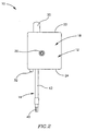
- Fig. 2 is a side face view of the wrench shown in Fig. 1;
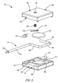
- Fig. 3 is an exploded perspective view of the wrench shown in Fig. 1;
- Fig. 4 is a perspective view of the rod shown in Figs. 1 to 3;
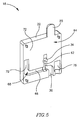
- Fig. 5 is a perspective view of a cover of the wrench shown in Fig. 3;
- Fig. 6 is a perspective view of a base of the wrench shown in Fig. 3;
- Fig. 7 is a perspective view of the wrench, showing the rod in a free position;
- Fig. 8 is a perspective view of the wrench, showing the rod in a biased position;
- Fig. 9 is the perspective view of the wrench shown in Fig. 7, with the cover removed; and
- Fig. 10 is the perspective view of the base of the wrench shown in Fig. 8, with the cover removed.
- Attention is drawn to Figs. 1 to 3, showing a
wrench 10 in accordance with a preferred embodiment of the present invention. Thewrench 10 comprises acasing 12 and arod 14. A portion of therod 14 can be rotated relative to thecasing 12 between a free position and a biased position, as will be further explained below. Thecasing 12 is of a generally rectangular shape, comprising abase 16 secured to acover 18. Acylindrical protrusion 20 extends from atop face 22 of the casing. - The
rod 14 emerges from abottom face 24 of thecasing 12 through anelongated rod aperture 26, having abase aperture section 28 which extends into thebase 16 and acover aperture section 30 extending into thecover 18. Anindicator 32 is disposed in thebottom face 24, and protrudes from thecasing 12. The indicator may be a light source such as a Light Emitting Diode (LED) or an audio source, such as a buzzer. A threadedadjusting bore 34 extends through thecover 18 and accommodates an adjustingbolt 36. - As shown in Figs. 3 and 4, the
rod 14 comprises a drivenportion 38 and adriving tip 40, with astraight section 42 extending therebetween. The drivenportion 38, having a general U-shape, comprises aclamped section 44, arotating section 46 generally parallel thereto, and acantilever section 48 disposed therebetween, thecantilever section 48 being generally perpendicular both to the clampedsection 44 and therotating section 46, and parallel to thestraight section 42 of therod 14. - The
indicator 32 forms a part of an electric circuit, comprising abattery 50, abattery terminal 52, abattery lead 54 and arod lead 56. Both therod lead 56 and thebattery lead 54 are disposed in a baseinner face 58. Therod lead 56 connects theindicator 32 to therod 14 which, being made of metal, forms a part of the electric circuit. Thebattery lead 54 connects theindicator 32 to a first pole, while thebattery terminal 52 contacts a second pole of thebattery 50. - The
rod 14 is accommodated in thebase 16, in a generally U-shapedbase channel 60, disposed in the baseinner face 58, thebase channel 60 terminating in thebase aperture section 28. Thebase channel 60 has a base channel depth which is approximately equal to a diameter of therod 14. - As shown in Fig. 5, a
terminal channel 62, is formed in a coverinner face 64 and meets the threadedadjusting bore 34. Thecover aperture section 30 is disposed in the coverinner face 64, and extends into arotation relief section 66 of a generally S-shapedcover relief channel 68, therotation relief section 66 being generally parallel to thebottom face 24 of thecasing 12. Therotation relief section 66 merges with acantilever relief section 70 extending perpendicularly thereto. Thecover relief channel 68 has a cover relief channel depth which is approximately equal to the rod diameter of therod 14. Thecantilever relief section 70 terminates in aflat clamping portion 72 of the coverinner face 64, adjacent thetop face 22 of thecasing 12. - When the
wrench 10 is assembled, therod 14 is accommodated in thebase channel 60. Since the base channel depth is approximately equal to the rod diameter, therod 14 does not protrude much above the baseinner face 58. Thebattery 50 is accommodated in abattery well 74, and theindicator 32 is located in anindicator receptacle 76. The adjustingbolt 36 is threaded into the threadedadjusting bore 34, and thebattery terminal 52 is located in theterminal channel 62 in the coverinner face 64. Thecover 18 is secured to thebase 16, so that the baseinner face 58 and the coverinner face 64 abut, and theclamped section 44 of therod 14 is secured in thebase channel 60 by theflat clamping portion 72 of the coverinner face 64. The adjustingbolt 36 urges thebattery terminal 52 away from theterminal channel 62, so that afirst terminal section 78 contacts one of the poles of thebattery 50. - Figs. 7 and 8 show the assembled
wrench 10 in the two extreme positions of the rotation of therod 14 relative to thecasing 12. Fig. 7 shows therod 14 in its free position, in which thestraight section 42 therod 14 emerges from thebase aperture section 28 of thebase 16. Fig. 8 shows therod 14 in the biased position, in which thestraight section 42 of therod 14 emerges from thecover aperture section 30 of thecover 18. - With no torque applied to the
wrench 10, therod 14 is in the free position, with the drivenportion 38 of therod 14 nesting in thebase 16 of thecasing 12. The electrical circuit remains open as long as therod 14 and thebattery terminal 52 do not touch. Therefore, in the free position, the electrical circuit remains open and theindicator 32 is not activated. - Reference is now made to Figs. 9 and 10. When using the
torque wrench 10, the drivingtip 40 is inserted into a fastener (not shown), and torque is applied to thecasing 12, which bears on the clampedsection 44 of therod 14, causing the clampedsection 44, and thus theentire rod 14, to rotate, and tighten the fastener. As the torque applied to thecasing 12 is increased, the torque applied to the clampedsection 44 of therod 14 is correspondingly increased, and therotating section 46 resiliently twists thecantilever section 48, so that the rotatingsection 46 shifts angularly relative to the clampedsection 44. A portion of therotating section 46 distal thecantilever section 48 is urged away from, and out of, thebase channel 60, to above the baseinner face 58, and into therotation relief section 66 in thecover 18, and the rod moves from the free position towards the biased position. The angular shift of therotating section 46 continues to increase, as the applied torque is increased, until at a given torque the biased position of therod 14 is reached and contact is made between therotating section 46 of therod 14, and thebattery terminal 52, causing the electric circuit to close. Consequently, theindicator 32 is activated, indicating that the biased position, and therefore, the pre-determined torque, has been reached. - The pre-determined torque required to rotate the
rod 14 into contact with thebattery terminal 52 in the biased position can be adjusted using the adjustingbolt 36. Turning the adjustingbolt 36 clockwise causes it to advance into the threaded adjusting bore 34, urging thebattery terminal 52 away from the coverinner face 64 and towards the rotatingsection 46 of therod 14, thus reducing the amount of twist needed for therod 14 to contact thebattery terminal 52. Turning the adjustingbolt 36 anti-clockwise urges thebattery terminal 52 away from the rotatingsection 46 of therod 14, increasing the amount of twist required to move therod 14 into contact with thebattery terminal 52, therefore increasing the torque required to activate theindicator 32. Thus, the adjustingbolt 36 adjusts the amount of torque required to activate the indicator. - Although the present invention has been described to a certain degree of particularity, it should be understood that various alterations and modifications could be made without departing from the scope of the invention as hereinafter claimed.
Claims (8)
- A wrench (10) comprising a rod (14) and a casing (12);
the casing (12) comprises a base (16) and a cover (18) secured together,
the rod (14) having a substantially U-shaped driven portion (38), a driving tip (40), and a straight section (42) extending therebetween;
the driven portion (38) having a clamped section (44), a rotating section (46) and a cantilever section (48) extending therebetween;
the clamped section (44) being securely clamped in the casing (12);
the rotating section (46) being rotatable between a free position and a biased position; ; characterized in that
the cantilever section (48) is substantially parallel to the straight section (42) of the rod (14), so that
in the free position the rotating section (46) of the rod (14) nests in a base channel (60) in the base (16), substantially below a base inner face (58); and
in the biased position at least a portion of the rotating section (46) of the rod (14) is located above the base inner face (58) in a rotation relief channel (66) in a cover inner face (64), thereby closing an electric circuit and activating an indicator (32). - The wrench (10) of claim 1, wherein the clamped section (44) and the rotating section (46) are substantially perpendicular to the cantilever section (48).
- The wrench (10) of claim 1, wherein the electric circuit comprises a battery (50) housed in the casing (12).
- The wrench (10) of claim 3, wherein the electric circuit comprises the rod (14) and a battery terminal (52) connected to the battery (50).
- The wrench (10) of claim 4, wherein the electrical circuit closes when the rod (14) is in the biased position by a contact formed between the rod (14) and the battery terminal (52).
- The wrench (10) of claim 5, wherein the biased position is externally adjustable by an adjusting bolt (36) threading into a threaded adjusting bore (34) and bearing against the terminal (52).
- The wrench (10) of claim 1, wherein the indicator (32) is a Light Emitting Diode (LED).
- The wrench (10) of claim 1, wherein the indicator (32) is a buzzer.
Priority Applications (1)
| Application Number | Priority Date | Filing Date | Title |
|---|---|---|---|
| PL04799308T PL1687122T3 (en) | 2003-11-24 | 2004-11-01 | Torque indicating wrench |
Applications Claiming Priority (2)
| Application Number | Priority Date | Filing Date | Title |
|---|---|---|---|
| IL159027A IL159027A (en) | 2003-11-24 | 2003-11-24 | Torque indicating wrench |
| PCT/IL2004/000999 WO2005049279A1 (en) | 2003-11-24 | 2004-11-01 | Torque indicating wrench |
Publications (2)
| Publication Number | Publication Date |
|---|---|
| EP1687122A1 EP1687122A1 (en) | 2006-08-09 |
| EP1687122B1 true EP1687122B1 (en) | 2007-06-06 |
Family
ID=34044297
Family Applications (1)
| Application Number | Title | Priority Date | Filing Date |
|---|---|---|---|
| EP04799308A Expired - Lifetime EP1687122B1 (en) | 2003-11-24 | 2004-11-01 | Torque indicating wrench |
Country Status (13)
| Country | Link |
|---|---|
| US (1) | US7093522B2 (en) |
| EP (1) | EP1687122B1 (en) |
| JP (1) | JP4621688B2 (en) |
| KR (1) | KR100890703B1 (en) |
| CN (1) | CN100408274C (en) |
| AT (1) | ATE363966T1 (en) |
| BR (1) | BRPI0416814B1 (en) |
| DE (1) | DE602004006893T2 (en) |
| ES (1) | ES2286700T3 (en) |
| IL (1) | IL159027A (en) |
| PL (1) | PL1687122T3 (en) |
| RU (1) | RU2361722C2 (en) |
| WO (1) | WO2005049279A1 (en) |
Families Citing this family (9)
| Publication number | Priority date | Publication date | Assignee | Title |
|---|---|---|---|---|
| US8366727B2 (en) * | 2006-06-01 | 2013-02-05 | Ethicon Endo-Surgery, Inc. | Tissue pad ultrasonic surgical instrument |
| US7406900B1 (en) * | 2007-05-02 | 2008-08-05 | Chih-Ching Hsieh | Tension alert hand tool |
| TWI369279B (en) * | 2010-02-08 | 2012-08-01 | Kabo Tool Co | Wrench |
| DE102010023705A1 (en) | 2010-06-14 | 2011-12-15 | Eva Fahrzeugtechnik Gmbh | Torque spanner e.g. standard hexagonal spanner, for roof carrier of motor vehicle, has inner housing that extends partially inside outer housing, where inner housing detects torsion of torsion body at location |
| WO2013008297A1 (en) * | 2011-07-11 | 2013-01-17 | 株式会社信防エディックス | Wrench |
| US9956673B2 (en) * | 2014-08-20 | 2018-05-01 | Tohnichi Mfg. Co., Ltd. | Tightening tool |
| US11130216B2 (en) * | 2018-08-22 | 2021-09-28 | Frank Hermansen | Selectively adjustable torque indicating tool |
| CN112530753B (en) * | 2020-11-26 | 2023-02-03 | 广东电网有限责任公司清远供电局 | Binding post and use its circuit breaker |
| US20250387888A1 (en) * | 2022-07-01 | 2025-12-25 | Apex Brands, Inc. | Electronic torque wrench with torque overshoot compensation |
Family Cites Families (27)
| Publication number | Priority date | Publication date | Assignee | Title |
|---|---|---|---|---|
| US2250941A (en) * | 1938-05-21 | 1941-07-29 | Automotive Maintenance Mach Co | Torque measuring wrench |
| US3076362A (en) * | 1961-07-28 | 1963-02-05 | Sweeney Mfg Co B K | Torque wrench |
| US3485117A (en) * | 1968-02-26 | 1969-12-23 | Mcculloch Corp | Torque wrench |
| US3967513A (en) * | 1975-08-29 | 1976-07-06 | Myrdal Jack L | Torque signaling attachment for torque wrench |
| US4215599A (en) * | 1978-08-28 | 1980-08-05 | Khartli, Inc. | Torque multiplier assembly |
| US4244434A (en) * | 1978-12-04 | 1981-01-13 | Wilson John T R | Electronically indicating torque wrench |
| US4328709A (en) * | 1980-04-18 | 1982-05-11 | Schramm Wayne E | Electronic audio visual torque indicator adapter |
| US4314490A (en) * | 1980-06-30 | 1982-02-09 | Stone Gregory M | Torque wrench with alarm indicator |
| US4535659A (en) * | 1983-11-02 | 1985-08-20 | Yang Tai Her | Torque limiting wrench with an audio alarm |
| DE3534520A1 (en) * | 1985-09-27 | 1987-04-09 | Bosch Gmbh Robert | Torque wrench |
| US4664001A (en) * | 1985-11-25 | 1987-05-12 | Deuer Manufacturing Inc. | Torque wrench with audio and visual indicator |
| JPH0417339Y2 (en) * | 1987-10-13 | 1992-04-17 | ||
| US4938109A (en) * | 1989-04-10 | 1990-07-03 | Carlos A. Torres | Torque hold system and method |
| US4958541A (en) * | 1989-10-13 | 1990-09-25 | Snap-On Tools Corporation | Electronic torque wrench with tactile indication |
| JP2526075Y2 (en) * | 1990-10-13 | 1997-02-12 | ティアツク株式会社 | Torque Wrench |
| US5130700A (en) * | 1991-03-04 | 1992-07-14 | Snap-On Tools Corporation | Electronic torque wrench and overshoot compensation circuit therefor |
| JPH06167401A (en) * | 1992-12-01 | 1994-06-14 | Kubota Corp | Screwing torque checker |
| SE9401096L (en) * | 1994-03-31 | 1995-05-22 | Gustav Rennerfelt | torque wrench |
| CN2270603Y (en) * | 1996-07-02 | 1997-12-17 | 重庆建筑大学 | Torque indicating type wrench |
| US5911154A (en) * | 1997-10-30 | 1999-06-08 | Hsieh; Chih-Ching | Wrench torque value calibrating apparatus |
| US6070506A (en) * | 1998-07-20 | 2000-06-06 | Snap-On Tools Company | Ratchet head electronic torque wrench |
| US6314846B1 (en) * | 1999-10-20 | 2001-11-13 | Sun Microsystems, Inc. | Torque wrench |
| US6523442B2 (en) * | 2000-12-07 | 2003-02-25 | Acradyne Inc. | Torque tool assembly |
| DE10103730C2 (en) * | 2001-01-26 | 2003-04-30 | Wolfgang B Thoerner | screwdriver |
| TW488356U (en) * | 2001-10-29 | 2002-05-21 | Hou-Fei Hu | Small sized torque wrench with constant torque |
| TW500027U (en) * | 2001-10-29 | 2002-08-21 | Hou-Fei Hu | Micro-small torque wrench with constant torque value |
| TW542771B (en) * | 2002-06-03 | 2003-07-21 | Hou-Fei Hu | Replaceable miniature torque tool |
-
2003
- 2003-11-24 IL IL159027A patent/IL159027A/en active IP Right Grant
-
2004
- 2004-09-20 US US10/943,993 patent/US7093522B2/en not_active Expired - Lifetime
- 2004-11-01 RU RU2006117372/02A patent/RU2361722C2/en active
- 2004-11-01 AT AT04799308T patent/ATE363966T1/en active
- 2004-11-01 DE DE602004006893T patent/DE602004006893T2/en not_active Expired - Lifetime
- 2004-11-01 KR KR1020067009983A patent/KR100890703B1/en not_active Expired - Lifetime
- 2004-11-01 ES ES04799308T patent/ES2286700T3/en not_active Expired - Lifetime
- 2004-11-01 PL PL04799308T patent/PL1687122T3/en unknown
- 2004-11-01 BR BRPI0416814A patent/BRPI0416814B1/en not_active IP Right Cessation
- 2004-11-01 WO PCT/IL2004/000999 patent/WO2005049279A1/en not_active Ceased
- 2004-11-01 EP EP04799308A patent/EP1687122B1/en not_active Expired - Lifetime
- 2004-11-01 CN CNB200480034624XA patent/CN100408274C/en not_active Expired - Lifetime
- 2004-11-01 JP JP2006540770A patent/JP4621688B2/en not_active Expired - Lifetime
Also Published As
| Publication number | Publication date |
|---|---|
| ATE363966T1 (en) | 2007-06-15 |
| BRPI0416814A (en) | 2007-03-06 |
| EP1687122A1 (en) | 2006-08-09 |
| DE602004006893T2 (en) | 2008-01-31 |
| DE602004006893D1 (en) | 2007-07-19 |
| PL1687122T3 (en) | 2007-08-31 |
| US20050109172A1 (en) | 2005-05-26 |
| CN100408274C (en) | 2008-08-06 |
| KR20060100446A (en) | 2006-09-20 |
| JP4621688B2 (en) | 2011-01-26 |
| IL159027A0 (en) | 2004-05-12 |
| RU2361722C2 (en) | 2009-07-20 |
| CN1886234A (en) | 2006-12-27 |
| KR100890703B1 (en) | 2009-03-27 |
| BRPI0416814B1 (en) | 2015-11-10 |
| US7093522B2 (en) | 2006-08-22 |
| IL159027A (en) | 2008-03-20 |
| RU2006117372A (en) | 2008-01-10 |
| JP2007512152A (en) | 2007-05-17 |
| ES2286700T3 (en) | 2007-12-01 |
| WO2005049279A1 (en) | 2005-06-02 |
Similar Documents
| Publication | Publication Date | Title |
|---|---|---|
| US11192223B2 (en) | Tool holding apparatus and power tool, and impact tool | |
| JP5059230B2 (en) | Tongue-free spiral coil insert insertion tool | |
| US7093522B2 (en) | Torque indicating wrench | |
| US11298804B2 (en) | Pushing lever structure of ratchet wrench | |
| US7024966B2 (en) | Positionable power screwdriver | |
| US8545143B2 (en) | Router with a cutting depth adjustment mechanism | |
| US8132333B2 (en) | Pair of compasses | |
| WO2005074101A1 (en) | Integrated brush-holder retention system | |
| US4375040A (en) | Brush holder assembly | |
| AU2003292094A1 (en) | Fixing device for a seat belt winder | |
| JP2004034286A (en) | Hand-held tooling device with torque limiter | |
| US9651228B2 (en) | Lighting device for hand tool | |
| KR20190091168A (en) | Multifunction cutting machine | |
| US6927353B2 (en) | Device switch for electric hand-held tools | |
| CA2548604C (en) | Rotary circuit selection device with crown detent | |
| AU1470402A (en) | Power force adjustment for a setting tool | |
| CA2589447C (en) | Power hand tool | |
| JP2023019287A (en) | Torque Wrench | |
| JP2007109461A (en) | Terminal block device | |
| JP2008270658A (en) | Variable resistor | |
| HK1168573B (en) | Insertion tool for tangless spiray coil insert | |
| JPH1019023A (en) | Set screw |
Legal Events
| Date | Code | Title | Description |
|---|---|---|---|
| PUAI | Public reference made under article 153(3) epc to a published international application that has entered the european phase |
Free format text: ORIGINAL CODE: 0009012 |
|
| 17P | Request for examination filed |
Effective date: 20060523 |
|
| AK | Designated contracting states |
Kind code of ref document: A1 Designated state(s): AT BE BG CH CY CZ DE DK EE ES FI FR GB GR HU IE IS IT LI LU MC NL PL PT RO SE SI SK TR |
|
| RAP1 | Party data changed (applicant data changed or rights of an application transferred) |
Owner name: NEW ISCAR LTD. |
|
| RAP1 | Party data changed (applicant data changed or rights of an application transferred) |
Owner name: ISCAR LTD. |
|
| RAP1 | Party data changed (applicant data changed or rights of an application transferred) |
Owner name: ISCAR LTD. |
|
| GRAP | Despatch of communication of intention to grant a patent |
Free format text: ORIGINAL CODE: EPIDOSNIGR1 |
|
| DAX | Request for extension of the european patent (deleted) | ||
| GRAS | Grant fee paid |
Free format text: ORIGINAL CODE: EPIDOSNIGR3 |
|
| GRAA | (expected) grant |
Free format text: ORIGINAL CODE: 0009210 |
|
| AK | Designated contracting states |
Kind code of ref document: B1 Designated state(s): AT BE BG CH CY CZ DE DK EE ES FI FR GB GR HU IE IS IT LI LU MC NL PL PT RO SE SI SK TR |
|
| PG25 | Lapsed in a contracting state [announced via postgrant information from national office to epo] |
Ref country code: LI Free format text: LAPSE BECAUSE OF FAILURE TO SUBMIT A TRANSLATION OF THE DESCRIPTION OR TO PAY THE FEE WITHIN THE PRESCRIBED TIME-LIMIT Effective date: 20070606 Ref country code: CH Free format text: LAPSE BECAUSE OF FAILURE TO SUBMIT A TRANSLATION OF THE DESCRIPTION OR TO PAY THE FEE WITHIN THE PRESCRIBED TIME-LIMIT Effective date: 20070606 Ref country code: FI Free format text: LAPSE BECAUSE OF FAILURE TO SUBMIT A TRANSLATION OF THE DESCRIPTION OR TO PAY THE FEE WITHIN THE PRESCRIBED TIME-LIMIT Effective date: 20070606 |
|
| REG | Reference to a national code |
Ref country code: GB Ref legal event code: FG4D |
|
| REG | Reference to a national code |
Ref country code: CH Ref legal event code: EP |
|
| REG | Reference to a national code |
Ref country code: IE Ref legal event code: FG4D |
|
| REF | Corresponds to: |
Ref document number: 602004006893 Country of ref document: DE Date of ref document: 20070719 Kind code of ref document: P |
|
| REG | Reference to a national code |
Ref country code: SE Ref legal event code: TRGR |
|
| REG | Reference to a national code |
Ref country code: PL Ref legal event code: T3 |
|
| ET | Fr: translation filed | ||
| REG | Reference to a national code |
Ref country code: ES Ref legal event code: FG2A Ref document number: 2286700 Country of ref document: ES Kind code of ref document: T3 |
|
| NLV1 | Nl: lapsed or annulled due to failure to fulfill the requirements of art. 29p and 29m of the patents act | ||
| REG | Reference to a national code |
Ref country code: CH Ref legal event code: PL |
|
| PG25 | Lapsed in a contracting state [announced via postgrant information from national office to epo] |
Ref country code: BE Free format text: LAPSE BECAUSE OF FAILURE TO SUBMIT A TRANSLATION OF THE DESCRIPTION OR TO PAY THE FEE WITHIN THE PRESCRIBED TIME-LIMIT Effective date: 20070606 |
|
| PG25 | Lapsed in a contracting state [announced via postgrant information from national office to epo] |
Ref country code: PT Free format text: LAPSE BECAUSE OF FAILURE TO SUBMIT A TRANSLATION OF THE DESCRIPTION OR TO PAY THE FEE WITHIN THE PRESCRIBED TIME-LIMIT Effective date: 20071106 Ref country code: IS Free format text: LAPSE BECAUSE OF FAILURE TO SUBMIT A TRANSLATION OF THE DESCRIPTION OR TO PAY THE FEE WITHIN THE PRESCRIBED TIME-LIMIT Effective date: 20071006 Ref country code: BG Free format text: LAPSE BECAUSE OF FAILURE TO SUBMIT A TRANSLATION OF THE DESCRIPTION OR TO PAY THE FEE WITHIN THE PRESCRIBED TIME-LIMIT Effective date: 20070906 Ref country code: NL Free format text: LAPSE BECAUSE OF FAILURE TO SUBMIT A TRANSLATION OF THE DESCRIPTION OR TO PAY THE FEE WITHIN THE PRESCRIBED TIME-LIMIT Effective date: 20070606 Ref country code: SI Free format text: LAPSE BECAUSE OF FAILURE TO SUBMIT A TRANSLATION OF THE DESCRIPTION OR TO PAY THE FEE WITHIN THE PRESCRIBED TIME-LIMIT Effective date: 20070606 |
|
| PG25 | Lapsed in a contracting state [announced via postgrant information from national office to epo] |
Ref country code: SK Free format text: LAPSE BECAUSE OF FAILURE TO SUBMIT A TRANSLATION OF THE DESCRIPTION OR TO PAY THE FEE WITHIN THE PRESCRIBED TIME-LIMIT Effective date: 20070606 |
|
| PLBE | No opposition filed within time limit |
Free format text: ORIGINAL CODE: 0009261 |
|
| STAA | Information on the status of an ep patent application or granted ep patent |
Free format text: STATUS: NO OPPOSITION FILED WITHIN TIME LIMIT |
|
| PG25 | Lapsed in a contracting state [announced via postgrant information from national office to epo] |
Ref country code: DK Free format text: LAPSE BECAUSE OF FAILURE TO SUBMIT A TRANSLATION OF THE DESCRIPTION OR TO PAY THE FEE WITHIN THE PRESCRIBED TIME-LIMIT Effective date: 20070606 Ref country code: GR Free format text: LAPSE BECAUSE OF FAILURE TO SUBMIT A TRANSLATION OF THE DESCRIPTION OR TO PAY THE FEE WITHIN THE PRESCRIBED TIME-LIMIT Effective date: 20070907 |
|
| 26N | No opposition filed |
Effective date: 20080307 |
|
| PG25 | Lapsed in a contracting state [announced via postgrant information from national office to epo] |
Ref country code: RO Free format text: LAPSE BECAUSE OF FAILURE TO SUBMIT A TRANSLATION OF THE DESCRIPTION OR TO PAY THE FEE WITHIN THE PRESCRIBED TIME-LIMIT Effective date: 20070606 |
|
| PG25 | Lapsed in a contracting state [announced via postgrant information from national office to epo] |
Ref country code: MC Free format text: LAPSE BECAUSE OF NON-PAYMENT OF DUE FEES Effective date: 20071130 |
|
| PG25 | Lapsed in a contracting state [announced via postgrant information from national office to epo] |
Ref country code: IE Free format text: LAPSE BECAUSE OF NON-PAYMENT OF DUE FEES Effective date: 20071101 |
|
| PG25 | Lapsed in a contracting state [announced via postgrant information from national office to epo] |
Ref country code: EE Free format text: LAPSE BECAUSE OF FAILURE TO SUBMIT A TRANSLATION OF THE DESCRIPTION OR TO PAY THE FEE WITHIN THE PRESCRIBED TIME-LIMIT Effective date: 20070606 |
|
| PG25 | Lapsed in a contracting state [announced via postgrant information from national office to epo] |
Ref country code: CY Free format text: LAPSE BECAUSE OF FAILURE TO SUBMIT A TRANSLATION OF THE DESCRIPTION OR TO PAY THE FEE WITHIN THE PRESCRIBED TIME-LIMIT Effective date: 20070606 |
|
| PG25 | Lapsed in a contracting state [announced via postgrant information from national office to epo] |
Ref country code: LU Free format text: LAPSE BECAUSE OF NON-PAYMENT OF DUE FEES Effective date: 20071101 |
|
| PG25 | Lapsed in a contracting state [announced via postgrant information from national office to epo] |
Ref country code: HU Free format text: LAPSE BECAUSE OF FAILURE TO SUBMIT A TRANSLATION OF THE DESCRIPTION OR TO PAY THE FEE WITHIN THE PRESCRIBED TIME-LIMIT Effective date: 20071207 |
|
| PG25 | Lapsed in a contracting state [announced via postgrant information from national office to epo] |
Ref country code: IT Free format text: LAPSE BECAUSE OF NON-PAYMENT OF DUE FEES Effective date: 20091101 |
|
| PGRI | Patent reinstated in contracting state [announced from national office to epo] |
Ref country code: IT Effective date: 20110616 |
|
| REG | Reference to a national code |
Ref country code: FR Ref legal event code: PLFP Year of fee payment: 12 |
|
| REG | Reference to a national code |
Ref country code: FR Ref legal event code: PLFP Year of fee payment: 13 |
|
| REG | Reference to a national code |
Ref country code: FR Ref legal event code: PLFP Year of fee payment: 14 |
|
| REG | Reference to a national code |
Ref country code: FR Ref legal event code: PLFP Year of fee payment: 15 |
|
| PGFP | Annual fee paid to national office [announced via postgrant information from national office to epo] |
Ref country code: PL Payment date: 20230928 Year of fee payment: 20 |
|
| PGFP | Annual fee paid to national office [announced via postgrant information from national office to epo] |
Ref country code: GB Payment date: 20231010 Year of fee payment: 20 |
|
| PGFP | Annual fee paid to national office [announced via postgrant information from national office to epo] |
Ref country code: TR Payment date: 20231013 Year of fee payment: 20 Ref country code: SE Payment date: 20231011 Year of fee payment: 20 Ref country code: IT Payment date: 20230929 Year of fee payment: 20 Ref country code: FR Payment date: 20231011 Year of fee payment: 20 Ref country code: DE Payment date: 20231010 Year of fee payment: 20 Ref country code: CZ Payment date: 20231009 Year of fee payment: 20 Ref country code: AT Payment date: 20231009 Year of fee payment: 20 |
|
| PGFP | Annual fee paid to national office [announced via postgrant information from national office to epo] |
Ref country code: ES Payment date: 20231228 Year of fee payment: 20 |
|
| REG | Reference to a national code |
Ref country code: DE Ref legal event code: R071 Ref document number: 602004006893 Country of ref document: DE |
|
| REG | Reference to a national code |
Ref country code: GB Ref legal event code: PE20 Expiry date: 20241031 |
|
| REG | Reference to a national code |
Ref country code: ES Ref legal event code: FD2A Effective date: 20241126 |
|
| REG | Reference to a national code |
Ref country code: AT Ref legal event code: MK07 Ref document number: 363966 Country of ref document: AT Kind code of ref document: T Effective date: 20241101 |
|
| REG | Reference to a national code |
Ref country code: SE Ref legal event code: EUG |
|
| PG25 | Lapsed in a contracting state [announced via postgrant information from national office to epo] |
Ref country code: GB Free format text: LAPSE BECAUSE OF EXPIRATION OF PROTECTION Effective date: 20241031 |
|
| PG25 | Lapsed in a contracting state [announced via postgrant information from national office to epo] |
Ref country code: CZ Free format text: LAPSE BECAUSE OF EXPIRATION OF PROTECTION Effective date: 20241101 |
|
| PG25 | Lapsed in a contracting state [announced via postgrant information from national office to epo] |
Ref country code: ES Free format text: LAPSE BECAUSE OF EXPIRATION OF PROTECTION Effective date: 20241102 |
|
| PG25 | Lapsed in a contracting state [announced via postgrant information from national office to epo] |
Ref country code: GB Free format text: LAPSE BECAUSE OF EXPIRATION OF PROTECTION Effective date: 20241031 Ref country code: ES Free format text: LAPSE BECAUSE OF EXPIRATION OF PROTECTION Effective date: 20241102 Ref country code: CZ Free format text: LAPSE BECAUSE OF EXPIRATION OF PROTECTION Effective date: 20241101 |