EP1685910A1 - Masking an engine block during coating application - Google Patents
Masking an engine block during coating application Download PDFInfo
- Publication number
- EP1685910A1 EP1685910A1 EP06250428A EP06250428A EP1685910A1 EP 1685910 A1 EP1685910 A1 EP 1685910A1 EP 06250428 A EP06250428 A EP 06250428A EP 06250428 A EP06250428 A EP 06250428A EP 1685910 A1 EP1685910 A1 EP 1685910A1
- Authority
- EP
- European Patent Office
- Prior art keywords
- coating
- cylinder bore
- cylinder
- gas
- engine block
- Prior art date
- Legal status (The legal status is an assumption and is not a legal conclusion. Google has not performed a legal analysis and makes no representation as to the accuracy of the status listed.)
- Granted
Links
Images



Classifications
-
- C—CHEMISTRY; METALLURGY
- C23—COATING METALLIC MATERIAL; COATING MATERIAL WITH METALLIC MATERIAL; CHEMICAL SURFACE TREATMENT; DIFFUSION TREATMENT OF METALLIC MATERIAL; COATING BY VACUUM EVAPORATION, BY SPUTTERING, BY ION IMPLANTATION OR BY CHEMICAL VAPOUR DEPOSITION, IN GENERAL; INHIBITING CORROSION OF METALLIC MATERIAL OR INCRUSTATION IN GENERAL
- C23C—COATING METALLIC MATERIAL; COATING MATERIAL WITH METALLIC MATERIAL; SURFACE TREATMENT OF METALLIC MATERIAL BY DIFFUSION INTO THE SURFACE, BY CHEMICAL CONVERSION OR SUBSTITUTION; COATING BY VACUUM EVAPORATION, BY SPUTTERING, BY ION IMPLANTATION OR BY CHEMICAL VAPOUR DEPOSITION, IN GENERAL
- C23C4/00—Coating by spraying the coating material in the molten state, e.g. by flame, plasma or electric discharge
- C23C4/12—Coating by spraying the coating material in the molten state, e.g. by flame, plasma or electric discharge characterised by the method of spraying
- C23C4/14—Coating by spraying the coating material in the molten state, e.g. by flame, plasma or electric discharge characterised by the method of spraying for coating elongate material
- C23C4/16—Wires; Tubes
-
- B—PERFORMING OPERATIONS; TRANSPORTING
- B05—SPRAYING OR ATOMISING IN GENERAL; APPLYING FLUENT MATERIALS TO SURFACES, IN GENERAL
- B05B—SPRAYING APPARATUS; ATOMISING APPARATUS; NOZZLES
- B05B12/00—Arrangements for controlling delivery; Arrangements for controlling the spray area
- B05B12/16—Arrangements for controlling delivery; Arrangements for controlling the spray area for controlling the spray area
- B05B12/18—Arrangements for controlling delivery; Arrangements for controlling the spray area for controlling the spray area using fluids, e.g. gas streams
-
- C—CHEMISTRY; METALLURGY
- C23—COATING METALLIC MATERIAL; COATING MATERIAL WITH METALLIC MATERIAL; CHEMICAL SURFACE TREATMENT; DIFFUSION TREATMENT OF METALLIC MATERIAL; COATING BY VACUUM EVAPORATION, BY SPUTTERING, BY ION IMPLANTATION OR BY CHEMICAL VAPOUR DEPOSITION, IN GENERAL; INHIBITING CORROSION OF METALLIC MATERIAL OR INCRUSTATION IN GENERAL
- C23C—COATING METALLIC MATERIAL; COATING MATERIAL WITH METALLIC MATERIAL; SURFACE TREATMENT OF METALLIC MATERIAL BY DIFFUSION INTO THE SURFACE, BY CHEMICAL CONVERSION OR SUBSTITUTION; COATING BY VACUUM EVAPORATION, BY SPUTTERING, BY ION IMPLANTATION OR BY CHEMICAL VAPOUR DEPOSITION, IN GENERAL
- C23C4/00—Coating by spraying the coating material in the molten state, e.g. by flame, plasma or electric discharge
- C23C4/01—Selective coating, e.g. pattern coating, without pre-treatment of the material to be coated
-
- B—PERFORMING OPERATIONS; TRANSPORTING
- B05—SPRAYING OR ATOMISING IN GENERAL; APPLYING FLUENT MATERIALS TO SURFACES, IN GENERAL
- B05B—SPRAYING APPARATUS; ATOMISING APPARATUS; NOZZLES
- B05B13/00—Machines or plants for applying liquids or other fluent materials to surfaces of objects or other work by spraying, not covered by groups B05B1/00 - B05B11/00
- B05B13/06—Machines or plants for applying liquids or other fluent materials to surfaces of objects or other work by spraying, not covered by groups B05B1/00 - B05B11/00 specially designed for treating the inside of hollow bodies
- B05B13/0627—Arrangements of nozzles or spray heads specially adapted for treating the inside of hollow bodies
- B05B13/0636—Arrangements of nozzles or spray heads specially adapted for treating the inside of hollow bodies by means of rotatable spray heads or nozzles
-
- Y—GENERAL TAGGING OF NEW TECHNOLOGICAL DEVELOPMENTS; GENERAL TAGGING OF CROSS-SECTIONAL TECHNOLOGIES SPANNING OVER SEVERAL SECTIONS OF THE IPC; TECHNICAL SUBJECTS COVERED BY FORMER USPC CROSS-REFERENCE ART COLLECTIONS [XRACs] AND DIGESTS
- Y10—TECHNICAL SUBJECTS COVERED BY FORMER USPC
- Y10T—TECHNICAL SUBJECTS COVERED BY FORMER US CLASSIFICATION
- Y10T29/00—Metal working
- Y10T29/49—Method of mechanical manufacture
- Y10T29/49229—Prime mover or fluid pump making
- Y10T29/4927—Cylinder, cylinder head or engine valve sleeve making
-
- Y—GENERAL TAGGING OF NEW TECHNOLOGICAL DEVELOPMENTS; GENERAL TAGGING OF CROSS-SECTIONAL TECHNOLOGIES SPANNING OVER SEVERAL SECTIONS OF THE IPC; TECHNICAL SUBJECTS COVERED BY FORMER USPC CROSS-REFERENCE ART COLLECTIONS [XRACs] AND DIGESTS
- Y10—TECHNICAL SUBJECTS COVERED BY FORMER USPC
- Y10T—TECHNICAL SUBJECTS COVERED BY FORMER US CLASSIFICATION
- Y10T29/00—Metal working
- Y10T29/49—Method of mechanical manufacture
- Y10T29/49229—Prime mover or fluid pump making
- Y10T29/4927—Cylinder, cylinder head or engine valve sleeve making
- Y10T29/49272—Cylinder, cylinder head or engine valve sleeve making with liner, coating, or sleeve
-
- Y—GENERAL TAGGING OF NEW TECHNOLOGICAL DEVELOPMENTS; GENERAL TAGGING OF CROSS-SECTIONAL TECHNOLOGIES SPANNING OVER SEVERAL SECTIONS OF THE IPC; TECHNICAL SUBJECTS COVERED BY FORMER USPC CROSS-REFERENCE ART COLLECTIONS [XRACs] AND DIGESTS
- Y10—TECHNICAL SUBJECTS COVERED BY FORMER USPC
- Y10T—TECHNICAL SUBJECTS COVERED BY FORMER US CLASSIFICATION
- Y10T29/00—Metal working
- Y10T29/49—Method of mechanical manufacture
- Y10T29/49826—Assembling or joining
- Y10T29/49885—Assembling or joining with coating before or during assembling
-
- Y—GENERAL TAGGING OF NEW TECHNOLOGICAL DEVELOPMENTS; GENERAL TAGGING OF CROSS-SECTIONAL TECHNOLOGIES SPANNING OVER SEVERAL SECTIONS OF THE IPC; TECHNICAL SUBJECTS COVERED BY FORMER USPC CROSS-REFERENCE ART COLLECTIONS [XRACs] AND DIGESTS
- Y10—TECHNICAL SUBJECTS COVERED BY FORMER USPC
- Y10T—TECHNICAL SUBJECTS COVERED BY FORMER US CLASSIFICATION
- Y10T29/00—Metal working
- Y10T29/49—Method of mechanical manufacture
- Y10T29/4998—Combined manufacture including applying or shaping of fluent material
- Y10T29/49982—Coating
Definitions
- the invention relates to techniques for coating a cylinder bore on an engine block. Embodiments of the invention also relate to an apparatus, a system and a method.
- An engine block may be designed to include a coating, for example a ferrous material, coated on the inner surface of the cylinder bore.
- a coating may allow engine designs having reduced overall weight of the engine block and enhanced abrasion resistant properties for inner surfaces of the cylinder bores.
- a coating may be particularly useful for aluminium engine blocks.
- One method to prevent a coating from adhering to a lower portion of the adjacent cylinder bore requires covering lower parts of the cylinder bore with a masking shield prior to spraying the cylinder bore with a coating.
- the masking shield protects the lower portion of the cylinder bore when the coating is formed on the inner surface of the engine cylinder bore. After spraying, the masking shield must be removed.
- masking shields are labour-intensive. Further, masking shields are consumable items that contribute to engine manufacturing expenses. In addition, since a coating may have formed a continuous layer connecting an inner surface of a cylinder bore to a masking shield, removal of a masking shield runs the risk of breaking and damaging the coating formed on the inner surface of the cylinder bore.
- a method of applying a coating to an engine block comprising: spraying the coating on an inner surface of a cylinder bore of a first cylinder bank of the engine block and shielding a cylinder bore of a second cylinder bank of the engine block from the sprayed coating with a gas flow while spraying the coating on the inner surface.
- the cylinder bore of the first cylinder bank opposes the cylinder bore of the second cylinder bank.
- the cylinder bore of the first cylinder bank defines a first central axis line and the cylinder bore of the second cylinder bank defines a second central axis line, the first central axis line intersects the second central axis line, the spraying is accomplished using a coating gun having a coating nozzle, and the coating nozzle is positioned within the cylinder bore of the first cylinder bank near an end of the cylinder bore of the first cylinder bank that is closest to the intersection of the first central axis line and the second central axis line.
- the gas flow is directed to a crankcase side of the cylinder bore of the first cylinder bank and the cylinder bore of the second cylinder bank.
- the method may comprise shielding an inner wall of the crankcase with the gas flow.
- the gas flow is directed from a nozzle of a gas gun.
- the gas flow is a first gas flow and the nozzle is a first nozzle, further comprising shielding an inner wall of the crankcase with a second gas flow directed from a second nozzle while spraying the coating on the inner surface.
- a system for applying a coating to an engine block comprising: a coating gun that discharges a coating material to form the coating on an inner surface of a cylinder bore of a first cylinder bank of the engine block; and a nozzle that discharges gas from within a cylinder bore of a second cylinder bank of the engine block to a crankcase side of the cylinder bore of the first cylinder bank and the cylinder bore of the second cylinder bank such that the cylinder bore of the second cylinder bank is shielded from the discharge of the coating material.
- the nozzle is located in a side of the cylinder bore of the second cylinder bank that is closest to the cylinder bore of the first cylinder bank.
- the cylinder bore of the first cylinder bank opposes the cylinder bore of the second cylinder bank.
- the cylinder bore of the first cylinder bank defines a first central axis line and cylinder bore of the second cylinder bank defines a second central axis line, the first central axis line intersects the second central axis line, the coating gun has a coating nozzle, and the coating nozzle is positioned within the cylinder bore of the first cylinder bank near an end of the cylinder bore of the first cylinder bank that is closest to the intersection of the first central axis line and the second central axis line.
- the nozzle includes multiple outlets arranged in a half-circle around an inner surface of the cylinder bore of the second cylinder bank, wherein the half-circle is within a side of the cylinder bore of the second cylinder bank closest to the cylinder bore of the first cylinder bank.
- the nozzle is positioned near an opening of the cylinder bore of the second cylinder bank on a crankcase side of the cylinder bore of the second cylinder bank.
- the nozzle is positioned such that the nozzle is shielded from the discharge of the coating material by an engine block bulkhead separating two cylinder banks of the engine block.
- the nozzle includes a first outlet creating a first gas flow that shields a crank journal wall of the engine block from the discharge of the coating material, and a second outlet creating a second gas flow that shields the cylinder bore of the second cylinder bank from the discharge of the coating material.
- the nozzle is a first nozzle in a set of nozzles
- each cylinder bore in the second cylinder bank includes one nozzle from the set of nozzles
- the set of nozzles create gas flow that shields each cylinder bore in the second cylinder bank from the discharge of the coating material.
- the system may further comprise an outer gas nozzle that discharges gas to shield an inner wall of a crankcase of the engine block from the discharge of the coating material.
- the system may further comprise a work stand, wherein the outer gas nozzle is located on the work stand and the engine block is installed on the work stand.
- the outer gas nozzle also discharges gas to shield a crank journal wall of the engine block from the discharge of the coating material.
- the system may further comprise a gas cooler that supplies the gas to the nozzle, wherein the gas is cooled to decrease adhesion of the coating material to surfaces of the engine bock outside the cylinder bore of the first cylinder bank.
- the system may further comprise insulation covering a portion of the nozzle to limit condensation on the nozzle.
- a system comprising means for applying a coating to an inner surface of a cylinder bore of an engine block and means for shielding a surface of the engine block with a gas flow to prevent the coating from adhering to the surface of the engine block.
- a nozzle comprising a housing sized to fit within a first cylinder bore in a first cylinder bank of an engine block and an outlet to create a gas flow from within the first cylinder bore to a crankcase side of the engine block during application of a coating to an inner surface of a second cylinder bore in a second cylinder bank of the engine block.
- the gas flow forms an airflow wall between the first cylinder bore and the second cylinder bore.
- the nozzle may further comprise a set of outlets, wherein the outlet is one of the set of outlets, wherein each of the set of outlets are arranged in a half-circle such that each of the set of outlets are substantially equidistant from an interior surface the first cylinder bore.
- the housing has a rectangular shape.
- Embodiments of the invention prevent or reduce adherence of a coating to a cylinder bore without using masking materials by protecting the lower portion of the cylinder bore with a gas gun.
- Embodiments of the invention may be particularly useful for forming a coating on the inner surface of the cylinder bores in one cylinder bank while protecting cylinder bores in an opposing cylinder bank, e.g., in a V-type engine.
- a method of applying a coating to an engine block may comprise spraying the coating on an inner surface of a cylinder bore of a first cylinder bank of the engine block, and shielding a cylinder bore of a second cylinder bank of the engine block from the sprayed coating with a gas flow while spraying the coating on the inner surface.
- a system for applying a coating to an engine block may comprise a coating gun that discharges a coating material to form the coating on an inner surface of a cylinder bore of a first cylinder bank of the engine block.
- the system may further comprise a nozzle that discharges gas from within a cylinder bore of a second cylinder bank of the engine block to a crankcase side of the cylinder bore of the first cylinder bank and the cylinder bore of the second cylinder bank such that the cylinder bore of the second cylinder bank is shielded from the discharge of the coating material.
- Another system may comprise means for applying a coating to an inner surface of a cylinder bore of an engine block, and means for shielding a surface of the engine block with a gas flow to prevent the coating from adhering to the surface of the engine block.
- a nozzle may comprise a housing sized to fit within a first cylinder bore in a first cylinder bank of an engine block, and an outlet to create a gas flow from within the first cylinder bore to a crankcase side of the engine block during application of a coating to an inner surface of a second cylinder bore in a second cylinder bank of the engine block.
- Embodiments of the invention may provide one or more advantages. For example, since masking materials are reduced or not used, the process of removing the masking material from the engine block may be reduced or eliminated. This also helps to reduce manufacturing expenses by avoiding the use of consumable masking materials on which the spray material adheres. In addition, embodiments of the invention prevent damage to an applied a coating on the inner surface of the cylinder bore during removal of a masking material.
- FIG. 1 is a view of section A-A from FIG. 2.
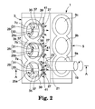
- FIG. 2 is a side view of engine block 1 as viewed from the side of the mounting surface.
- the engine block 1 represents a V-type engine with the left and right banks 3 and 5, each bank having three cylinder bores, 7a, 7b, 7c and 9a, 9b, 9c respectively, arranged in straight lines toward the axial direction of the crankshaft (not shown).
- the cylinder bores 7a, 7b, 7c form the cylinder bank on the left bank 3 and the cylinder bores 9a, 9b, 9c form the cylinder bank on the right bank 5 are arranged opposite to one another.
- Each of the cylinder bores 7a, 7b, 7c oppose each of the cylinder bores 9a, 9b, 9c and vice versa.
- the extensions of central axes SL of the cylinder bores 7a, 7b, 7c and SR of the cylinder bores 9a, 9b, 9c intersect with each other as viewed from the axial direction of the crankshaft, for example, the view shown in FIG. 1.
- the engine block 1 may be designed to include a coating, e.g., a ferrous material, coated on the inner surface of the cylinder bore.
- engine block 1 may be an aluminium engine block.
- Such a coating may enhance abrasion resistant properties for inner surfaces of the cylinder bores 7a, 7b, 7c and 9a, 9b, 9c.
- the engine block 1 as shown in FIG. 1, includes crankcase 11 on the lower end of cylinder bores 7a, 7b, 7c and 9a, 9b, 9c.
- the oil pan rail 13a of flange 13, protruding to both sides of the crankcase 11, is fixed on the hollow centre work stand 15.
- the crank journal 17 rotationally supports the crankshaft (not shown).
- a coating gun 19 As shown in FIG. 2, enters the cylinder bore 9a in one cylinder bank on the right bank 5, and the centre of the spray gun is aligned with the central axis SR of the cylinder bore 9a.
- the spray gun 19 rotates about the central axis SR as it moves along the central axis SR, spraying a coating material 23 from the spray nozzle 21. In this manner, a coating gun 19 forms a coating on the inner surface of the cylinder bore 9a.
- gas guns 25a, 25b, 25c Prior to spraying a coating, to protect lower portions of the cylinder bores 9a, 9b and 9c, gas guns 25a, 25b, 25c are inserted into the cylinder bores 7a, 7b and 7c, respectively, each opposite to the cylinder bores 9a, 9b and 9c. A gas 27 is then discharged out of the gas guns 25a, 25b, 25c.
- the gas 27 may consist of air.
- Gas guns 25a, 25b, and 25c are substantially similar; however, the following description will only refer to gas gun 25a, and cylinder bores 9a and 7a.
- the gas gun 25a is arranged as the semi-circular shaped gun housing 29, which is located along the lines of the inner surface of cylinder bore 7a at the near side of the cylinder bore 9a.
- the gun housing 29 has an inner portion 31 and an outer portion 33.
- the gas nozzle 35 is fixed in the space between inner portion 31 and outer portion 33.
- the gas nozzle 35 forms gas path 37, which includes an expansion space 39 prior to multiple outlets 41.
- the multiple outlets 41 are arranged along the lines of the semi-circular gun housing 29. In other words, the outlets 41 of the gas nozzle 35 form a semi-circle along the inner portion 31 of the cylinder bore at the near side of the cylinder bore 9a.
- Gas 27 is supplied from the gas supply equipment 42 to gas path 37.
- the gun housing 29 is longer near the wall of the cylinder bore and shorter near the centre of the cylinder bore.
- the tip 29a is wedge shaped, which is aligned with the gas outlets of nozzle 41.
- the length of the multiple outlets of nozzle 41 is the longest on the side of the cylinder bore 9a. The outlet length gradually gets shorter at positions farther from 9a, the nozzle located on the left end in FIG. 1 being the shortest.
- a coating is formed all over the cylinder bore 9a inner surface by inserting a coating gun 19 into the cylinder bore 9a on the right bank 5, rotating while advancing it in the direction of the axis, and jetting a coating material 23 from a coating nozzle 21 on its tip. Simultaneously, the gas ventilation equipment 44 suctions out the gas in the engine block 1 from the lower side of the work stand 15 and pulls clean gas 45 in.
- the gas guns 25a, 25b, 25c are inserted into the cylinder bores 7a, 7b, 7c on the left bank 3 respectively, opposite to the cylinder bore 9a, and the gas supplied from the gas supply equipment 42 is sprayed as the gas 27 from the tip of each outlet 41.
- the gas 27 that sprays from each outlet 41 of the gas guns 25a, 25b, 25c are arranged between the right and left flange parts 13 in the crankcase, and directed towards a range of angles ⁇ between arrows B and C.
- the direction of the gas spray of each outlet 41 on the gas nozzle 35 is the opening part on the opposite side of the cylinder bore in the crankcase that communicates with the cylinder bore.
- a coating gun 19 is located at the terminal end of the cylinder bore 9a, and a coating nozzle 21 is directed towards the engine block bulkhead 43.
- some of a coating material 23 that sprays from a coating nozzle 21 flows towards the opposing cylinder bore 7a and comes very close to entering the cylinder bore 7a.
- the gas 27 that discharges from the gas gun 25a alters the direction of this flow downward, thereby preventing or reducing a coating material 23 from adhering to the inner surface of the opposing cylinder bore 7a.
- the gas 27 spraying from the gas guns 25b, 25c prevents a coating material 23 from adhering to the cylinder bores 7b, 7c adjacent to the cylinder bore 7a.
- the outlets of nozzle 41 are located near the opening on the side of the cylinder bore 7a where a coating material 23 may enter the cylinder bore 7a to prevent a coating from adhering to the cylinder bore 7a.
- the outlets 41 are located forming a semi-circular arc covering about half the inner surface of the cylinder bore 7a closest to the cylinder bore 9a that receives a coating.
- the outlets of nozzle 41 are arranged in a half-circle such that each of the set of outlets is substantially equidistant from an interior surface the cylinder bore 7a. This arrangement enables the gas 27 that sprays from each outlet 41 to block the spray materials passing below the engine block bulkhead 43.
- the gas gun 25a that is inserted into the cylinder bore 7a is located such that the tip 29a is behind line L.
- Line L is an extension of the straight line that connects the spray from nozzle 21 of a coating gun 19 to the end of the engine block bulkhead 43 between the cylinder bore 7a and 9a, which is on the upper side in FIG. 1.
- gas gun 25a is substantially shielded from a coating material 23 by the engine block bulkhead 43. This prevents a coating material 23 from adhering to nozzle 41, which may prolong the use of the gas gun 25a.
- gas gun 25a projected beyond line L some of a coating material 23 may adhere to the gas discharging mouth of the outlet 41 and reduce the functional life of gas gun 25a.
- the direction of the gas discharging from each outlet is set such that the gas 27 and the ventilation gas 45 merge smoothly and flow downwards.
- the flow of the ventilation gas 45 is not disturbed much by gas 27, enabling the spraying process to be performed efficiently.
- coating masking may be performed by discharging the gas from the same gas supply equipment 42 and inserting the gas guns 25A, 25b and 25c into cylinder bores 7a, 7b and 7c simultaneously.
- coating of cylinder bores 9a, 9b and 9c may be performed successively or simultaneously without allowing a coating to adhere to the cylinder bores 7a, 7b and 7c during the coating of any of cylinder bores 9a, 9b and 9c.
- the gas 27 when spraying the cylinder bore 9a, the gas 27 prevents a coating material 23 from adhering to the cylinder bore 7b and 7c. In such embodiments, the gas 27 may be sprayed only from the gas gun 25a rather than from each gas guns 25a, 25b, and 25c during the spraying of the cylinder bore 9a.
- a valve When using the same gas supply source (gas supply equipment 42) for the gas guns 25a, 25b, 25c, a valve may installed in the middle of the gas piping (not shown) to direct gas only to gas gun 25a.
- coating masking may be performed for each of three cylinder bores 9a, 9b, 9c consecutively, simultaneously or two at a time.
- the gas gun(s) 25a, 25b and 25c corresponding to the cylinder bore(s) 7a, 7b and 7c that are adjacent to each of the cylinder bores 9a, 9b, 9c being sprayed should be activated.
- all gas gun(s) in cylinder bore(s) opposing a cylinder bore being sprayed may be activated.
- the gas 27 is supplied because of concern over the entrance of a coating material 23 due to the shape of the opening on the crankcase 11 of the cylinder bores 7a, 7b, 7c in the cylinder bank opposing the cylinder bore 9a that opposes the opening of the cylinder bore 9a.
- the cylinder bores 9a, 9b, 9c are parallel with one another and their openings on the crankcase 11 side are not opposed; therefore, there is no risk of entry of a coating material 23 into cylinder bores 9b or 9c.
- a coating gun 19 After forming a coating on the cylinder bores 9a, 9b and 9c on the right bank 5, a coating gun 19 forms a coating on the cylinder bores 7a, 7b and 7c. This can be performed the same way as described above, by inserting the gas guns 25a, 25b and 25c into the cylinder bores 9a, 9b and 9c to discharge the gas. This time, a coating from a coating gun 19 is prevented from adhering to the cylinder bores 9a, 9b and 9c.
- the ventilation gas amount Q1 suctioned by the gas ventilation equipment 44 is larger than the gas flow amount Q3 that the ventilation gas amount Q2 supplies to the gas gun 25a. This allows the assured draining of a coating material 23 flowing to the crankcase 1 side out of the engine block 1.
- a coating when a coating is formed on the cylinder bore 9a, a coating does not adhere to the cylinder bores 7a, 7b, 7c by the gas 27 flowing to the cylinder bores 7a, 7b, 7c. If a coating is formed to the cylinder bore 9a without taking such measures, a coating will adhere to the cylinder bores 7a, 7b, 7c.
- the cylinder bores 7a, 7b, 7c are arranged further from a coating gun 19.
- the degree of adhesion of a coating attached to the cylinder bores 7a, 7b, and 7c is lower than that of a coating adhered to the cylinder bore 9a, which is problematic.
- a coating is formed by inserting a coating gun 19 to each of these cylinder bores 7a, 7b, 7c in the same way as the cylinder bore 9a.
- the low degree of adhesion of a coating remains for cylinder bores 7a, 7b, 7c, and a stable coating cannot be obtained.
- the cylinder bore may, by design, have a rough surface from a shot peening process. Such a rough surface increases the degree of adhesion. As a result, it is difficult to completely remove undesirable coating.
- a coating when a coating is formed on the cylinder bores 7a, 7b, 7c after forming a coating on the cylinder bores 9a, 9b, 9c, it can stabilize a coating and also facilitate the subsequent washing of the cylinder bores 9a, 9b, 9c by preventing a coating from adhering to the cylinder bores 9a, 9b, 9c on which a coating has been already formed by flowing gas to the side of the cylinder bores 9a, 9b, 9c.
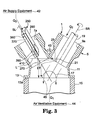
- FIG. 3 is a cross-sectional view corresponding to FIG. 1 showing coating masking techniques in the second exemplary embodiment of the invention.
- a gas gun 250 is used instead of the gas gun 25a, 25b and 25c described in FIG. 1. Except for the gas gun 250, the structure and notations for members are the same as that in FIG. 1.
- the gas gun 250 in the second exemplary embodiment has a gun housing 290 as a housing having a hollow rectangular shape. Inside the housing, the gas nozzle 350 is provided on the gas path 370 which includes an expansion space 390 prior to outlets 410. Multiple outlets 410 communicate with the expansion space 390.
- the direction of the gas spray of each outlet 410 on the gas nozzle 350 is inside the opening on the opposite side of the cylinder bore in the crankcase 11.
- the flow of the discharging gas 270 and that of the ventilation gas 45 merge smoothly and head downwards, the flow of the ventilation gas 45 is not greatly disturbed, and the spraying process may be performed efficiently.
- the tip of the gun housing 290, or the gas spray of each outlet 410 of the gas gun 250 is located on the side in the direction of gas discharging.
- the tip of the gun housing 290, or the gas spray of each outlet 410 of the gas gun 250 is located on the side in the direction of gas discharging.
- line L located behind line L such that gas nozzle 350 is shield from a coating material 23 by the engine block bulkhead 43.
- a coating material 23 may be completely prevented from adhering to the gas spray of the nozzle 410. Consequently, equipment cost can be reduced by the prolonged use of the gas gun 250.
- a coating gun 19 is located at the terminal end of the cylinder bore 9a, and outlet 21 is directed towards the engine block bulkhead 43.
- outlet 21 is directed towards the engine block bulkhead 43.
- a part of the spray material 23 from outlet 21 sprays towards the opposing cylinder bore 7a and comes close to entering it.
- the gas 270 that sprays from the gas gun 250 rectifies this flow downwards.
- a coating material 23 that sprays from outlet 21 is prevented from adhering to the inner surface of the opposing cylinder bores 7a, 7b, and 7c.
- the gun housing 290 has a rectangular shape, the whole shape of the gas gun 250 is simplified as compared with the first exemplary embodiment.
- the multiple outlets 410 may be formed by slanting some outlets 410 toward the outside rather than forming all the outlets parallel to the central axis of the cylinder bore. This can be easily applied to various engine blocks with different diameters, rendering them versatile.
- FIG. 4 is a cross-sectional view corresponding to the FIG. 1, showing the coating masking method of the third exemplary embodiment.
- FIG. 5 is a cross-sectional view of D-D in FIG. 4.
- the same symbols are allocated to the same part or corresponding part of each component in FIG. 1 and FIG. 2.
- FIG. 4 and FIG. 5 show an example of forming a coating on the cylinder bore 9b, wherein the gas gun 25b is inserted into the cylinder bore 7b opposing the cylinder bore 9b.
- the gas gun 25b in this embodiment has basically same structure as that shown in the FIG. 1. As shown in FIG. 5, it also include the crank journal wall oriented nozzles 51 and 53 that are directed to the crank journal walls 47 and 49 situated in the upper and the lower part in FIG. 5 respectively. Furthermore the third exemplary embodiment includes the cylinder bore oriented nozzle 55 directed to the cylinder bore 9b.
- the crank journal walls 47 and 49 comprise the crank journal 17 that rotationally supports the crankshaft (not shown).
- the multiple crank journal oriented outlets of nozzles 51 and 53 are arranged along the horizontal direction in FIG. 5 respectively. These nozzles are oriented to the lower portion of the cylinder bore of the crank journal walls 47 and 49 where a coating can be easily adhered.
- the multiple cylinder bore oriented outlets of nozzle 55 are arranged along the circular arc shape of gun housing 29 and are directed to the opening of crankcase 11 of the cylinder bore 9b.
- the outlets of nozzle 55 are arranged in a half-circle such that each of the set of outlets is substantially equidistant from an interior surface the cylinder bore 7b.
- the outer gas nozzles 57 and 59 are arranged on the work stand 15 that is located downward of the cylinder bore 9b on which a coating is formed. These nozzles are gas discharging nozzles that spray gaseous gas upward in FIG. 4.
- the outer gas nozzle 57 sprays the gas 61 toward the cylinder bore 9b along the inner wall 11 a of the crankcase 11. It is formed so as to open from within the wall of the work stand 15 to within the crankcase 11.
- the multiple gas outlets of nozzle 59 are arranged inside of the work stand 15 along the horizontal direction in FIG. 4 and discharge the gas 63 and 65 toward the crank journal walls 47 and 49 shown in the FIG. 5. These multiple outer gas outlets of nozzle 59 are arranged on the pipes extending in the perpendicular direction, and the lower end of the nozzle is communicated with the pipe 67 extending to the horizontal direction.
- the gas supply pipe 67 is connected to the continuous hole 15a, adjacent to the lower end of the outer gas nozzle 57.
- the outside of the continuous hole 15a also connects with the gas supply piping 69.
- the gas is supplied from a gas source (not shown).
- outer gas nozzle 59 may be oriented to focus gas on both of the crank journal walls 47 and 49 simultaneously. In other embodiments, outer gas nozzle 59 may focus gas on only crank journal walls 49, and a different outer gas nozzle may focus gas on crank journal walls 47.
- the gas 71 discharging from the cylinder bore oriented nozzle 55 prevents a coating material 23 from flowing to the opposing cylinder bore 7b and entering the cylinder bore 7b by altering the direction. Consequently, it can prevent some of a coating material 23 discharged from a coating nozzle 21 from adhering to the inner surface of the opposing cylinder bore 7b and 7a, 7c.
- the gas 73 and 75 discharging from the crank journal wall oriented nozzles 51 and 53 flow to the crank journal walls 47 and 49 respectively. This prevents a coating material 23 from adhering to the crank journal walls 47 and 49.
- the gas 63 and 65 discharging from the outer gas nozzle 59 flow to the crank journal walls 47 and 49 respectively. This prevents a coating material 23 from adhering to the crank journal walls 47 and 49.
- the gas 61 discharging from the outer gas nozzle 57 flows along the inner wall 11 a of the crankcase 11. This prevents a coating material 23 from adhering to the inner wall 11a of the crankcase 11.
- the speed and amount of the gas 61, 63, 65 discharging from the outer gas nozzles 57 and 59 are set such that a coating material 23 draining into the crankcase 11 does not flow back to the cylinder bore 9b.
- the ventilation gas amount Q1 is determined so that the gas amount Q2 entering the cylinder bore 9b exceeds the total gas amount Q3 supplied to the gas gun 25a and the gas amount Q4 supplied to the gas supply piping 69. This ensures a coating material 23 flowing out to the crankcase 11 is directed out of the engine block 1.
- the gas 61, 63, and 65 can be discharged accurately to the inner surface 11 a of the crankcase 11 and the crank journal wall 47 without adjusting the position of the outer gas nozzle 57 and 59, by installing the engine block 1 in the specified position on the work stand 15.
- the third exemplary embodiment includes the gas 61, 63, and 65 sprayed on the inner wall 11 a of the crankcase 11 and the crank journal walls 47 and 49 to prevent adhesion of the coating
- the degree of adhesion of a coating to the inner wall 11a of the crankcase 11 and the crank journal walls 47 and 49 is lower than that to the cylinder bore 9a.
- the distance between a coating gun 19 and the inner wall 11a of the crankcase 11 and the crank journal walls 47, 49 is greater than that between a coating gun 19 and the cylinder bore 9a. Furthermore, inner wall 11a of the crankcase 11 and the crank journal walls 47, 49 are not generally textured. Also, the inner wall 11a of the crankcase 11 and the crank journal walls 47, 49 are not processed after cast moulding as cylinder bores, and an oxide film remains, resulting in an even lower level of adhesion. For all of these reasons, a coating adhering to the inner surface 11a of the crankcase 11 and the crank journal walls 47, 49 can be removed, e.g., by subsequent washing.
- FIG. 6 is a cross-sectional view, showing the coating masking method of the engine block in the fourth exemplary embodiment of the invention.
- the same symbols are allocated to the same part or corresponding part of each component in FIG. 1.
- the gas gun 25a in this embodiment has basically same structure as that shown in the FIG. 1; however, the supply source that supplies gas to the gas gun 25a is cooling gas supply equipment 77 instead of the gas supply equipment 42 in FIG. 1, and the entire gas gun 25a or a portion thereof is insulated to reduce or prevent condensation.
- the cooling gas supplied from the cooling gas supply equipment 77 further decreases the adhesion of a coating material 23 to the cylinder bore 7a, the crank journal walls 47 and 49, and the inner surface 11 a of the crankcase 11.
- a coating adhering in this condition can be more easily removed by subsequent washing. For example, a coating temporally adhering to the cylinder bore 7a and the crank journal walls 47, 49 or the inner wall 11a of the crankcase 11 can be removed.
- the cooling gas into the gas gun 25a may result in condensation and water drops.
- these water drops flow out to the crankcase 11 side and this has adverse effects in forming a coating on the cylinder bore 9a due to the steam generated within the engine block 1.
- Cooled gas may be used in conjunction with any of the described embodiments.
- the gas 61, 63, 65 discharged from the outer gas nozzles 57, 59 may be substituted with cooling gas.
- the entire outer gas nozzles 57, 59 or a portion thereof may be insulated.
- a V-type engine was described.
- the invention can be applied to any engines and is particularly applicable to any arrangement including opposing cylinders.
- an engine may include additional cylinder banks or other arrangement of cylinders.
- opposing cylinders may be masked using the described techniques to prevent undesirable adhesion of the coating.
- the described embodiments may be readily adapted to mask additional portions of an engine block.
- the operation of a coating gun 19 and the gas guns 25a, 25b, 25c, and 250 may automated with a robotic mechanism, by manual operation of workers or a combination thereof.
Landscapes
- Chemical & Material Sciences (AREA)
- Engineering & Computer Science (AREA)
- Mechanical Engineering (AREA)
- Plasma & Fusion (AREA)
- Chemical Kinetics & Catalysis (AREA)
- Materials Engineering (AREA)
- Physics & Mathematics (AREA)
- Metallurgy (AREA)
- Organic Chemistry (AREA)
- Cylinder Crankcases Of Internal Combustion Engines (AREA)
- Coating By Spraying Or Casting (AREA)
- Pistons, Piston Rings, And Cylinders (AREA)
- Details Or Accessories Of Spraying Plant Or Apparatus (AREA)
Abstract
Description
- The invention relates to techniques for coating a cylinder bore on an engine block. Embodiments of the invention also relate to an apparatus, a system and a method.
- An engine block may be designed to include a coating, for example a ferrous material, coated on the inner surface of the cylinder bore. Such a coating may allow engine designs having reduced overall weight of the engine block and enhanced abrasion resistant properties for inner surfaces of the cylinder bores. For example, a coating may be particularly useful for aluminium engine blocks.
- It is desirable to prevent a coating from adhering to a lower portion of an adjacent cylinder bore. For example, if while spraying a coating on one cylinder bore, some amount of spray is directed to an adjacent cylinder bore, the spray in the adjacent cylinder bore will have a lower degree of adhesion. Thereafter, if the adjacent cylinder bore is coated, the coating in that cylinder bore will continue to have a low degree of adhesion to the cylinder bore. This may cause the coating in that cylinder bore to break free during engine operation, which may lead to poor engine performance or even engine failure.
- One method to prevent a coating from adhering to a lower portion of the adjacent cylinder bore requires covering lower parts of the cylinder bore with a masking shield prior to spraying the cylinder bore with a coating. The masking shield protects the lower portion of the cylinder bore when the coating is formed on the inner surface of the engine cylinder bore. After spraying, the masking shield must be removed.
- Removing masking shields is labour-intensive. Further, masking shields are consumable items that contribute to engine manufacturing expenses. In addition, since a coating may have formed a continuous layer connecting an inner surface of a cylinder bore to a masking shield, removal of a masking shield runs the risk of breaking and damaging the coating formed on the inner surface of the cylinder bore.
- It is an aim of the invention to address this issue. Other aims and advantages of the invention will become apparent from the following description, claims and drawings.
- According to aspects of the invention, there is provided an apparatus, a method, a system and a nozzle as set out in the appended claims.
- According to another aspect of the invention, there is provided a method of applying a coating to an engine block comprising: spraying the coating on an inner surface of a cylinder bore of a first cylinder bank of the engine block and shielding a cylinder bore of a second cylinder bank of the engine block from the sprayed coating with a gas flow while spraying the coating on the inner surface.
- In one embodiment, the cylinder bore of the first cylinder bank opposes the cylinder bore of the second cylinder bank.
- In one embodiment, the cylinder bore of the first cylinder bank defines a first central axis line and the cylinder bore of the second cylinder bank defines a second central axis line, the first central axis line intersects the second central axis line, the spraying is accomplished using a coating gun having a coating nozzle, and the coating nozzle is positioned within the cylinder bore of the first cylinder bank near an end of the cylinder bore of the first cylinder bank that is closest to the intersection of the first central axis line and the second central axis line.
- In one embodiment, the gas flow is directed to a crankcase side of the cylinder bore of the first cylinder bank and the cylinder bore of the second cylinder bank.
- While spraying the coating on the inner surface, the method may comprise shielding an inner wall of the crankcase with the gas flow.
- In one embodiment, the gas flow is directed from a nozzle of a gas gun.
- In one embodiment, the gas flow is a first gas flow and the nozzle is a first nozzle, further comprising shielding an inner wall of the crankcase with a second gas flow directed from a second nozzle while spraying the coating on the inner surface.
- According to yet another aspect of the invention there is provided a system for applying a coating to an engine block comprising: a coating gun that discharges a coating material to form the coating on an inner surface of a cylinder bore of a first cylinder bank of the engine block; and a nozzle that discharges gas from within a cylinder bore of a second cylinder bank of the engine block to a crankcase side of the cylinder bore of the first cylinder bank and the cylinder bore of the second cylinder bank such that the cylinder bore of the second cylinder bank is shielded from the discharge of the coating material.
- In one embodiment, the nozzle is located in a side of the cylinder bore of the second cylinder bank that is closest to the cylinder bore of the first cylinder bank.
- In one embodiment, the cylinder bore of the first cylinder bank opposes the cylinder bore of the second cylinder bank.
- In one embodiment, the cylinder bore of the first cylinder bank defines a first central axis line and cylinder bore of the second cylinder bank defines a second central axis line, the first central axis line intersects the second central axis line, the coating gun has a coating nozzle, and the coating nozzle is positioned within the cylinder bore of the first cylinder bank near an end of the cylinder bore of the first cylinder bank that is closest to the intersection of the first central axis line and the second central axis line.
- In one embodiment, the nozzle includes multiple outlets arranged in a half-circle around an inner surface of the cylinder bore of the second cylinder bank, wherein the half-circle is within a side of the cylinder bore of the second cylinder bank closest to the cylinder bore of the first cylinder bank.
- In one embodiment, the nozzle is positioned near an opening of the cylinder bore of the second cylinder bank on a crankcase side of the cylinder bore of the second cylinder bank.
- In one embodiment, the nozzle is positioned such that the nozzle is shielded from the discharge of the coating material by an engine block bulkhead separating two cylinder banks of the engine block.
- In one embodiment, the nozzle includes a first outlet creating a first gas flow that shields a crank journal wall of the engine block from the discharge of the coating material, and a second outlet creating a second gas flow that shields the cylinder bore of the second cylinder bank from the discharge of the coating material.
- In one embodiment, the nozzle is a first nozzle in a set of nozzles, each cylinder bore in the second cylinder bank includes one nozzle from the set of nozzles, and the set of nozzles create gas flow that shields each cylinder bore in the second cylinder bank from the discharge of the coating material.
- The system may further comprise an outer gas nozzle that discharges gas to shield an inner wall of a crankcase of the engine block from the discharge of the coating material.
- The system may further comprise a work stand, wherein the outer gas nozzle is located on the work stand and the engine block is installed on the work stand.
- In one embodiment, the outer gas nozzle also discharges gas to shield a crank journal wall of the engine block from the discharge of the coating material.
- The system may further comprise a gas cooler that supplies the gas to the nozzle, wherein the gas is cooled to decrease adhesion of the coating material to surfaces of the engine bock outside the cylinder bore of the first cylinder bank.
- The system may further comprise insulation covering a portion of the nozzle to limit condensation on the nozzle.
- According to a further aspect of the invention there is provided a system comprising means for applying a coating to an inner surface of a cylinder bore of an engine block and means for shielding a surface of the engine block with a gas flow to prevent the coating from adhering to the surface of the engine block.
- According to a still further aspect of the invention there is provided a nozzle comprising a housing sized to fit within a first cylinder bore in a first cylinder bank of an engine block and an outlet to create a gas flow from within the first cylinder bore to a crankcase side of the engine block during application of a coating to an inner surface of a second cylinder bore in a second cylinder bank of the engine block.
- In one embodiment, the gas flow forms an airflow wall between the first cylinder bore and the second cylinder bore.
- The nozzle may further comprise a set of outlets, wherein the outlet is one of the set of outlets, wherein each of the set of outlets are arranged in a half-circle such that each of the set of outlets are substantially equidistant from an interior surface the first cylinder bore. In one embodiment, the housing has a rectangular shape.
- Embodiments of the invention prevent or reduce adherence of a coating to a cylinder bore without using masking materials by protecting the lower portion of the cylinder bore with a gas gun. Embodiments of the invention may be particularly useful for forming a coating on the inner surface of the cylinder bores in one cylinder bank while protecting cylinder bores in an opposing cylinder bank, e.g., in a V-type engine.
- For example, a method of applying a coating to an engine block may comprise spraying the coating on an inner surface of a cylinder bore of a first cylinder bank of the engine block, and shielding a cylinder bore of a second cylinder bank of the engine block from the sprayed coating with a gas flow while spraying the coating on the inner surface.
- A system for applying a coating to an engine block may comprise a coating gun that discharges a coating material to form the coating on an inner surface of a cylinder bore of a first cylinder bank of the engine block. The system may further comprise a nozzle that discharges gas from within a cylinder bore of a second cylinder bank of the engine block to a crankcase side of the cylinder bore of the first cylinder bank and the cylinder bore of the second cylinder bank such that the cylinder bore of the second cylinder bank is shielded from the discharge of the coating material.
- Another system may comprise means for applying a coating to an inner surface of a cylinder bore of an engine block, and means for shielding a surface of the engine block with a gas flow to prevent the coating from adhering to the surface of the engine block.
- A nozzle may comprise a housing sized to fit within a first cylinder bore in a first cylinder bank of an engine block, and an outlet to create a gas flow from within the first cylinder bore to a crankcase side of the engine block during application of a coating to an inner surface of a second cylinder bore in a second cylinder bank of the engine block.
- The various aspects and embodiments set out in the preceding paragraphs and in the claims may be implemented individually or in any suitable combination.
- Embodiments of the invention may provide one or more advantages. For example, since masking materials are reduced or not used, the process of removing the masking material from the engine block may be reduced or eliminated. This also helps to reduce manufacturing expenses by avoiding the use of consumable masking materials on which the spray material adheres. In addition, embodiments of the invention prevent damage to an applied a coating on the inner surface of the cylinder bore during removal of a masking material.
- The present invention will now be described, by way of example only, with reference to the accompanying drawings in which:
- FIG. 1 is a cross-sectional view of A-A in FIG. 2 showing coating masking techniques in a first exemplary embodiment of the invention.
- FIG. 2 is a plain view of the
engine block 1 viewed from the side of the mounting surface in the first exemplary embodiment. - FIG. 3 is a cross-sectional view corresponding to FIG. 1 showing coating masking techniques in a second exemplary embodiment of the invention.
- FIG. 4 is a cross-sectional view corresponding to FIG. 1 showing coating masking techniques in a third exemplary embodiment of the invention.
- FIG. 5 is a cross-sectional view of D-D in FIG. 4.
- FIG. 6 is a cross-sectional view similar to FIG. 1, showing coating masking techniques in a fourth exemplary embodiment of the invention.
- A first exemplary embodiment of coating masking techniques is shown in FIG. 1, which is a view of section A-A from FIG. 2. FIG. 2 is a side view of
engine block 1 as viewed from the side of the mounting surface. In this example, theengine block 1 represents a V-type engine with the left andright banks - The cylinder bores 7a, 7b, 7c form the cylinder bank on the
left bank 3 and the cylinder bores 9a, 9b, 9c form the cylinder bank on theright bank 5 are arranged opposite to one another. Each of the cylinder bores 7a, 7b, 7c oppose each of the cylinder bores 9a, 9b, 9c and vice versa. The extensions of central axes SL of the cylinder bores 7a, 7b, 7c and SR of the cylinder bores 9a, 9b, 9c intersect with each other as viewed from the axial direction of the crankshaft, for example, the view shown in FIG. 1. - The
engine block 1 may be designed to include a coating, e.g., a ferrous material, coated on the inner surface of the cylinder bore. For example,engine block 1 may be an aluminium engine block. Such a coating may enhance abrasion resistant properties for inner surfaces of the cylinder bores 7a, 7b, 7c and 9a, 9b, 9c. - The
engine block 1, as shown in FIG. 1, includescrankcase 11 on the lower end of cylinder bores 7a, 7b, 7c and 9a, 9b, 9c. Theoil pan rail 13a offlange 13, protruding to both sides of thecrankcase 11, is fixed on the hollowcentre work stand 15. Thecrank journal 17 rotationally supports the crankshaft (not shown). - To create a coating, a
coating gun 19, as shown in FIG. 2, enters the cylinder bore 9a in one cylinder bank on theright bank 5, and the centre of the spray gun is aligned with the central axis SR of thecylinder bore 9a. Thespray gun 19 rotates about the central axis SR as it moves along the central axis SR, spraying acoating material 23 from thespray nozzle 21. In this manner, acoating gun 19 forms a coating on the inner surface of thecylinder bore 9a. - Prior to spraying a coating, to protect lower portions of the cylinder bores 9a, 9b and 9c,
gas guns gas 27 is then discharged out of thegas guns gas 27 may consist of air. -
Gas guns gas gun 25a, and cylinder bores 9a and 7a. Thegas gun 25a is arranged as the semi-circular shapedgun housing 29, which is located along the lines of the inner surface of cylinder bore 7a at the near side of thecylinder bore 9a. Thegun housing 29 has aninner portion 31 and anouter portion 33. Thegas nozzle 35 is fixed in the space betweeninner portion 31 andouter portion 33. - The
gas nozzle 35forms gas path 37, which includes anexpansion space 39 prior tomultiple outlets 41. Themultiple outlets 41 are arranged along the lines of thesemi-circular gun housing 29. In other words, theoutlets 41 of thegas nozzle 35 form a semi-circle along theinner portion 31 of the cylinder bore at the near side of thecylinder bore 9a.Gas 27 is supplied from thegas supply equipment 42 togas path 37. - In addition, the
gun housing 29 is longer near the wall of the cylinder bore and shorter near the centre of the cylinder bore. Thus, thetip 29a is wedge shaped, which is aligned with the gas outlets ofnozzle 41. Similarly, the length of the multiple outlets ofnozzle 41 is the longest on the side of thecylinder bore 9a. The outlet length gradually gets shorter at positions farther from 9a, the nozzle located on the left end in FIG. 1 being the shortest. - A coating is formed all over the cylinder bore 9a inner surface by inserting a
coating gun 19 into the cylinder bore 9a on theright bank 5, rotating while advancing it in the direction of the axis, and jetting acoating material 23 from acoating nozzle 21 on its tip. Simultaneously, thegas ventilation equipment 44 suctions out the gas in theengine block 1 from the lower side of thework stand 15 and pullsclean gas 45 in. - As the
coating gun 19 forms the coating, thegas guns left bank 3 respectively, opposite to thecylinder bore 9a, and the gas supplied from thegas supply equipment 42 is sprayed as thegas 27 from the tip of eachoutlet 41. - In FIG. 1, the
gas 27 that sprays from eachoutlet 41 of thegas guns flange parts 13 in the crankcase, and directed towards a range of angles θ between arrows B and C. In other words, the direction of the gas spray of eachoutlet 41 on thegas nozzle 35 is the opening part on the opposite side of the cylinder bore in the crankcase that communicates with the cylinder bore. - At this point, as shown in FIG. 1, a
coating gun 19 is located at the terminal end of thecylinder bore 9a, and acoating nozzle 21 is directed towards theengine block bulkhead 43. As a result, some of acoating material 23 that sprays from acoating nozzle 21 flows towards the opposing cylinder bore 7a and comes very close to entering thecylinder bore 7a. However, thegas 27 that discharges from thegas gun 25a alters the direction of this flow downward, thereby preventing or reducing acoating material 23 from adhering to the inner surface of the opposingcylinder bore 7a. Likewise, thegas 27 spraying from thegas guns coating material 23 from adhering to the cylinder bores 7b, 7c adjacent to thecylinder bore 7a. - As shown in FIG. 1, the outlets of
nozzle 41 are located near the opening on the side of the cylinder bore 7a where acoating material 23 may enter the cylinder bore 7a to prevent a coating from adhering to thecylinder bore 7a. In addition, theoutlets 41 are located forming a semi-circular arc covering about half the inner surface of the cylinder bore 7a closest to the cylinder bore 9a that receives a coating. In particular the outlets ofnozzle 41, are arranged in a half-circle such that each of the set of outlets is substantially equidistant from an interior surface thecylinder bore 7a. This arrangement enables thegas 27 that sprays from eachoutlet 41 to block the spray materials passing below theengine block bulkhead 43. - The
gas gun 25a that is inserted into thecylinder bore 7a is located such that thetip 29a is behind line L. Line L is an extension of the straight line that connects the spray fromnozzle 21 of acoating gun 19 to the end of theengine block bulkhead 43 between thecylinder bore gas gun 25a is substantially shielded from acoating material 23 by theengine block bulkhead 43. This prevents acoating material 23 from adhering tonozzle 41, which may prolong the use of thegas gun 25a. In contrast, ifgas gun 25a projected beyond line L, some of acoating material 23 may adhere to the gas discharging mouth of theoutlet 41 and reduce the functional life ofgas gun 25a. - The direction of the gas discharging from each outlet is set such that the
gas 27 and theventilation gas 45 merge smoothly and flow downwards. Thus, the flow of theventilation gas 45 is not disturbed much bygas 27, enabling the spraying process to be performed efficiently. - As described above, coating masking may be performed by discharging the gas from the same
gas supply equipment 42 and inserting thegas guns cylinder bores - In some embodiments, when spraying the
cylinder bore 9a, thegas 27 prevents acoating material 23 from adhering to thecylinder bore gas 27 may be sprayed only from thegas gun 25a rather than from eachgas guns cylinder bore 9a. When using the same gas supply source (gas supply equipment 42) for thegas guns gas gun 25a. - In addition, coating masking may be performed for each of three
cylinder bores - When a coating is formed on the
cylinder bore 9a, thegas 27 is supplied because of concern over the entrance of acoating material 23 due to the shape of the opening on thecrankcase 11 of the cylinder bores 7a, 7b, 7c in the cylinder bank opposing the cylinder bore 9a that opposes the opening of thecylinder bore 9a. However, the cylinder bores 9a, 9b, 9c are parallel with one another and their openings on thecrankcase 11 side are not opposed; therefore, there is no risk of entry of acoating material 23 into cylinder bores 9b or 9c. - After forming a coating on the cylinder bores 9a, 9b and 9c on the
right bank 5, acoating gun 19 forms a coating on the cylinder bores 7a, 7b and 7c. This can be performed the same way as described above, by inserting thegas guns coating gun 19 is prevented from adhering to the cylinder bores 9a, 9b and 9c. - In the first exemplary embodiment described above, the ventilation gas amount Q1 suctioned by the
gas ventilation equipment 44 is larger than the gas flow amount Q3 that the ventilation gas amount Q2 supplies to thegas gun 25a. This allows the assured draining of acoating material 23 flowing to thecrankcase 1 side out of theengine block 1. - As described above, in the first exemplary embodiment, when a coating is formed on the
cylinder bore 9a, a coating does not adhere to the cylinder bores 7a, 7b, 7c by thegas 27 flowing to the cylinder bores 7a, 7b, 7c. If a coating is formed to the cylinder bore 9a without taking such measures, a coating will adhere to the cylinder bores 7a, 7b, 7c. - In this case, compared with the cylinder bore 9a that actually performs a coating masking, the cylinder bores 7a, 7b, 7c are arranged further from a
coating gun 19. The degree of adhesion of a coating attached to the cylinder bores 7a, 7b, and 7c is lower than that of a coating adhered to thecylinder bore 9a, which is problematic. Thereafter, a coating is formed by inserting acoating gun 19 to each of these cylinder bores 7a, 7b, 7c in the same way as thecylinder bore 9a. However, the low degree of adhesion of a coating remains forcylinder bores - In this case, although any unwanted coating can be taken off, the cylinder bore may, by design, have a rough surface from a shot peening process. Such a rough surface increases the degree of adhesion. As a result, it is difficult to completely remove undesirable coating.
- Accordingly, as described in this embodiment, when a coating is formed on the
cylinder bore 9a, it is possible to increase the degree of adhesion of a coating formed on the cylinder bores 7a, 7b, 7c later by preventing a coating from adhering to the cylinder bores 7a, 7b, 7c by flowing thegas 27 to the cylinder bores 7a, 7b, 7c in the opposing cylinder banks. - In addition, when a coating is formed on the cylinder bores 7a, 7b, 7c after forming a coating on the cylinder bores 9a, 9b, 9c, it can stabilize a coating and also facilitate the subsequent washing of the cylinder bores 9a, 9b, 9c by preventing a coating from adhering to the cylinder bores 9a, 9b, 9c on which a coating has been already formed by flowing gas to the side of the cylinder bores 9a, 9b, 9c.
- FIG. 3 is a cross-sectional view corresponding to FIG. 1 showing coating masking techniques in the second exemplary embodiment of the invention. In this embodiment a
gas gun 250 is used instead of thegas gun gas gun 250, the structure and notations for members are the same as that in FIG. 1. - The
gas gun 250 in the second exemplary embodiment has agun housing 290 as a housing having a hollow rectangular shape. Inside the housing, thegas nozzle 350 is provided on thegas path 370 which includes anexpansion space 390 prior tooutlets 410.Multiple outlets 410 communicate with theexpansion space 390. - As in the first exemplary embodiment, the direction of the gas spray of each
outlet 410 on thegas nozzle 350 is inside the opening on the opposite side of the cylinder bore in thecrankcase 11. The flow of the discharginggas 270 and that of theventilation gas 45 merge smoothly and head downwards, the flow of theventilation gas 45 is not greatly disturbed, and the spraying process may be performed efficiently. - In addition, as in the first exemplary embodiment, the tip of the
gun housing 290, or the gas spray of eachoutlet 410 of thegas gun 250, is located on the side in the direction of gas discharging. Thus it is shown on the upper side in FIG. 3, located behind line L such thatgas nozzle 350 is shield from acoating material 23 by theengine block bulkhead 43. Here again, acoating material 23 may be completely prevented from adhering to the gas spray of thenozzle 410. Consequently, equipment cost can be reduced by the prolonged use of thegas gun 250. - In this second exemplary embodiment, a
coating gun 19 is located at the terminal end of thecylinder bore 9a, andoutlet 21 is directed towards theengine block bulkhead 43. In this condition, a part of thespray material 23 fromoutlet 21 sprays towards the opposing cylinder bore 7a and comes close to entering it. However, thegas 270 that sprays from thegas gun 250 rectifies this flow downwards. As a result, acoating material 23 that sprays fromoutlet 21 is prevented from adhering to the inner surface of the opposing cylinder bores 7a, 7b, and 7c. - According to the second exemplary embodiment, since the
gun housing 290 has a rectangular shape, the whole shape of thegas gun 250 is simplified as compared with the first exemplary embodiment. - In addition, as shown in FIG. 3, the
multiple outlets 410 may be formed by slanting someoutlets 410 toward the outside rather than forming all the outlets parallel to the central axis of the cylinder bore. This can be easily applied to various engine blocks with different diameters, rendering them versatile. - FIG. 4 is a cross-sectional view corresponding to the FIG. 1, showing the coating masking method of the third exemplary embodiment. FIG. 5 is a cross-sectional view of D-D in FIG. 4. In FIG. 4 and FIG. 5, the same symbols are allocated to the same part or corresponding part of each component in FIG. 1 and FIG. 2. Also FIG. 4 and FIG. 5 show an example of forming a coating on the
cylinder bore 9b, wherein thegas gun 25b is inserted into the cylinder bore 7b opposing thecylinder bore 9b. - The
gas gun 25b in this embodiment has basically same structure as that shown in the FIG. 1. As shown in FIG. 5, it also include the crank journal wall orientednozzles crank journal walls nozzle 55 directed to thecylinder bore 9b. Thecrank journal walls crank journal 17 that rotationally supports the crankshaft (not shown). - The multiple crank journal oriented outlets of
nozzles 51 and 53 (four outlets in this embodiment) are arranged along the horizontal direction in FIG. 5 respectively. These nozzles are oriented to the lower portion of the cylinder bore of thecrank journal walls - The multiple cylinder bore oriented outlets of nozzle 55 (five outlets in this embodiment) are arranged along the circular arc shape of
gun housing 29 and are directed to the opening ofcrankcase 11 of thecylinder bore 9b. In particular, the outlets ofnozzle 55 are arranged in a half-circle such that each of the set of outlets is substantially equidistant from an interior surface thecylinder bore 7b. - The
outer gas nozzles - The
outer gas nozzle 57 sprays thegas 61 toward the cylinder bore 9b along the inner wall 11 a of thecrankcase 11. It is formed so as to open from within the wall of the work stand 15 to within thecrankcase 11. - The multiple gas outlets of nozzle 59 (three outlets in this embodiment) are arranged inside of the work stand 15 along the horizontal direction in FIG. 4 and discharge the
gas crank journal walls nozzle 59 are arranged on the pipes extending in the perpendicular direction, and the lower end of the nozzle is communicated with thepipe 67 extending to the horizontal direction. - The
gas supply pipe 67 is connected to thecontinuous hole 15a, adjacent to the lower end of theouter gas nozzle 57. The outside of thecontinuous hole 15a also connects with thegas supply piping 69. The gas is supplied from a gas source (not shown). - The
outer gas nozzle 59 may be oriented to focus gas on both of thecrank journal walls outer gas nozzle 59 may focus gas on only crankjournal walls 49, and a different outer gas nozzle may focus gas on crankjournal walls 47. - In the third exemplary embodiment, the
gas 71 discharging from the cylinder bore orientednozzle 55 prevents acoating material 23 from flowing to the opposing cylinder bore 7b and entering the cylinder bore 7b by altering the direction. Consequently, it can prevent some of acoating material 23 discharged from acoating nozzle 21 from adhering to the inner surface of the opposing cylinder bore 7b and 7a, 7c. - In addition, the
gas nozzles crank journal walls coating material 23 from adhering to thecrank journal walls - Moreover, similarly to the previously described
gas gas outer gas nozzle 59 flow to thecrank journal walls coating material 23 from adhering to thecrank journal walls - Also, the
gas 61 discharging from theouter gas nozzle 57 flows along the inner wall 11 a of thecrankcase 11. This prevents acoating material 23 from adhering to the inner wall 11a of thecrankcase 11. - The speed and amount of the
gas outer gas nozzles coating material 23 draining into thecrankcase 11 does not flow back to thecylinder bore 9b. - In the third exemplary embodiment shown in FIG. 4, the ventilation gas amount Q1 is determined so that the gas amount Q2 entering the
cylinder bore 9b exceeds the total gas amount Q3 supplied to thegas gun 25a and the gas amount Q4 supplied to thegas supply piping 69. This ensures acoating material 23 flowing out to thecrankcase 11 is directed out of theengine block 1. - Since the
outer gas nozzles engine block 1 is installed, thegas crankcase 11 and thecrank journal wall 47 without adjusting the position of theouter gas nozzle engine block 1 in the specified position on thework stand 15. - While the third exemplary embodiment includes the
gas crankcase 11 and thecrank journal walls crankcase 11 and thecrank journal walls coating material 23 adheres to the inner wall 11 a of thecrankcase 11 and thecrank journal walls crankcase 11 and thecrank journal walls cylinder bore 9a. The distance between acoating gun 19 and the inner wall 11a of thecrankcase 11 and thecrank journal walls coating gun 19 and thecylinder bore 9a. Furthermore, inner wall 11a of thecrankcase 11 and thecrank journal walls crankcase 11 and thecrank journal walls crankcase 11 and thecrank journal walls - FIG. 6 is a cross-sectional view, showing the coating masking method of the engine block in the fourth exemplary embodiment of the invention. In FIG. 6, the same symbols are allocated to the same part or corresponding part of each component in FIG. 1.
- The
gas gun 25a in this embodiment has basically same structure as that shown in the FIG. 1; however, the supply source that supplies gas to thegas gun 25a is cooling gas supply equipment 77 instead of thegas supply equipment 42 in FIG. 1, and theentire gas gun 25a or a portion thereof is insulated to reduce or prevent condensation. - As compared to previously described embodiments, the cooling gas supplied from the cooling gas supply equipment 77 further decreases the adhesion of a
coating material 23 to thecylinder bore 7a, thecrank journal walls crankcase 11. - Since the degree of adhesion of a coating decreases at low temperature, a coating adhering in this condition can be more easily removed by subsequent washing. For example, a coating temporally adhering to the
cylinder bore 7a and thecrank journal walls crankcase 11 can be removed. - However, the cooling gas into the
gas gun 25a may result in condensation and water drops. When water drops appear, these water drops flow out to thecrankcase 11 side and this has adverse effects in forming a coating on the cylinder bore 9a due to the steam generated within theengine block 1. However, it is possible to prevent condensation on the outer wall surface of thegas gun 25a by insulating theentire gas gun 25a, including thegas nozzle 35 or a portion thereof. - Cooled gas may be used in conjunction with any of the described embodiments. For example, the
gas outer gas nozzles outer gas nozzles - Various embodiments of the invention have been described. However, various modifications can be made within the spirit of the invention. For example, in each of the above described embodiments, a V-type engine was described. The invention can be applied to any engines and is particularly applicable to any arrangement including opposing cylinders. For example, an engine may include additional cylinder banks or other arrangement of cylinders. In such cases, opposing cylinders may be masked using the described techniques to prevent undesirable adhesion of the coating. Furthermore, the described embodiments may be readily adapted to mask additional portions of an engine block. In addition, in each of the above described embodiments, the operation of a
coating gun 19 and thegas guns - This application claims priority from Japanese Patent Application No. 2005-021686, filed January 28, 2005, and Japanese Patent Application No. 2005-348463, filed December 2, 2005, the entire contents each of being incorporated herein by reference.
Claims (14)
- An apparatus for applying a coating to an engine block comprising:a coating gun for discharging a coating material to form the coating on an inner surface of a cylinder bore of a first cylinder bank of the engine block; anda nozzle for discharging gas from within a cylinder bore of a second cylinder bank of the engine block such that the cylinder bore of the second cylinder bank is shielded from the discharge of the coating material.
- An apparatus as claimed in claim 1 wherein:the cylinder bore of the first cylinder bank defines a first central axis line and cylinder bore of the second cylinder bank defines a second central axis line;the first central axis line intersects the second central axis line;the coating gun has a coating nozzle, andthe coating nozzle is arranged to be positioned within the cylinder bore of the first cylinder bank near an end of the cylinder bore of the first cylinder bank that is closest to the intersection of the first central axis line and the second central axis line.
- An apparatus as claimed in claim 1 or claim 2 wherein the nozzle includes a plurality of outlets arranged in a half-circle and wherein the nozzle is arranged to be positioned within the cylinder bore of the second cylinder bank such that the outlets lie adjacent to a side of said cylinder bore closest to the cylinder bore of the first cylinder bank.
- An apparatus as claimed in any preceding claim wherein the nozzle comprises:a first outlet for creating a first gas flow for shielding a crank journal wall of the engine block from the discharge of the coating material, anda second outlet for creating a second gas flow for shielding the cylinder bore of the second cylinder bank from the discharge of the coating material.
- An apparatus as claimed in any preceding claim further comprising an outer gas nozzle for discharging gas to shield an inner wall of a crankcase of the engine block and, optionally, a crank journal wall of the engine block, from the discharge of the coating material.
- An apparatus as claimed in any preceding claim further comprising a gas cooler for supplying the gas to the nozzle, the gas cooler being arranged to cool the gas so as to decrease adhesion of the coating material to surfaces of the engine bock outside the cylinder bore of the first cylinder bank.
- An apparatus as claimed in any preceding claim further comprising insulation covering a portion of the nozzle to limit condensation on the nozzle.
- A method of applying a coating to an engine block comprising:spraying the coating on an inner surface of a cylinder bore of a first cylinder bank of the engine block; andshielding a cylinder bore of a second cylinder bank of the engine block from the sprayed coating with a gas flow while spraying the coating on the inner surface.
- A method as claimed in claim 8 further comprising, while spraying the coating on the inner surface, shielding an inner wall of the crankcase with the gas flow.
- A method as claimed in claim 8 or claim 9 comprising positioning the nozzle near an opening of the cylinder bore of the second cylinder bank on a crankcase side thereof.
- A method as claimed in any of claims 8 to 10 comprising positioning the nozzle such that the nozzle is shielded from the discharge of the coating material by an engine block bulkhead separating two cylinder banks of the engine block.
- A system comprising:means for applying a coating to an inner surface of a cylinder bore of an engine block; andmeans for shielding a surface of the engine block with a gas flow to prevent the coating from adhering to the surface of the engine block.
- A nozzle comprising:a housing sized to fit within a first cylinder bore in a first cylinder bank of an engine block; andan outlet to create a gas flow from within the first cylinder bore to a crankcase side of the engine block during application of a coating to an inner surface of a second cylinder bore in a second cylinder bank of the engine block.
- A nozzle as claimed in claim 13 comprising a set of outlets, wherein the set of outlets is arranged in a half-circle such that, in use, each outlet of the set of outlets may be positioned substantially equidistant from an interior surface the first cylinder bore.
Applications Claiming Priority (2)
| Application Number | Priority Date | Filing Date | Title |
|---|---|---|---|
| JP2005021686 | 2005-01-28 | ||
| JP2005348463A JP4497086B2 (en) | 2005-01-28 | 2005-12-01 | Cylinder block spraying masking method, masking apparatus and gas jet nozzle |
Publications (2)
| Publication Number | Publication Date |
|---|---|
| EP1685910A1 true EP1685910A1 (en) | 2006-08-02 |
| EP1685910B1 EP1685910B1 (en) | 2009-03-25 |
Family
ID=36263756
Family Applications (1)
| Application Number | Title | Priority Date | Filing Date |
|---|---|---|---|
| EP06250428A Expired - Lifetime EP1685910B1 (en) | 2005-01-28 | 2006-01-26 | Masking an engine block during coating application |
Country Status (4)
| Country | Link |
|---|---|
| US (2) | US7823284B2 (en) |
| EP (1) | EP1685910B1 (en) |
| JP (1) | JP4497086B2 (en) |
| DE (1) | DE602006005848D1 (en) |
Cited By (4)
| Publication number | Priority date | Publication date | Assignee | Title |
|---|---|---|---|---|
| EP1884293A1 (en) * | 2006-07-24 | 2008-02-06 | Sulzer Metco AG | Masking system for masking a cylinder drill hole |
| EP2075074A1 (en) * | 2006-07-24 | 2009-07-01 | Sulzer Metco AG | Masking system for masking a crank case for a combustion engine |
| US8500907B2 (en) | 2006-07-24 | 2013-08-06 | Sulzer Metco Ag | Masking system for the masking of a cylinder bore |
| WO2014106573A1 (en) * | 2013-01-04 | 2014-07-10 | Ford-Werke Gmbh | Method for thermally coating a surface |
Families Citing this family (16)
| Publication number | Priority date | Publication date | Assignee | Title |
|---|---|---|---|---|
| JP4692052B2 (en) * | 2005-04-14 | 2011-06-01 | 日産自動車株式会社 | Thermal spray masking method and masking apparatus for cylinder block |
| DE102005024021B4 (en) * | 2005-05-25 | 2008-05-21 | Daimler Ag | Component with a pretreated and / or to be coated inner surface and method for its pretreatment and / or coating |
| JP4992409B2 (en) * | 2006-12-19 | 2012-08-08 | 日産自動車株式会社 | Thermal spray masking member and thermal spray masking method |
| JP2011220150A (en) * | 2010-04-06 | 2011-11-04 | Honda Motor Co Ltd | Cylinder bore and method for manufacturing the same |
| JP5835347B2 (en) * | 2011-12-22 | 2015-12-24 | 日産自動車株式会社 | Cylinder block manufacturing method and cylinder block |
| EP2799152B8 (en) * | 2013-05-03 | 2016-02-24 | Oerlikon Metco AG, Wohlen | Processing device for processing a workpiece surface |
| JP6167897B2 (en) * | 2013-12-27 | 2017-07-26 | トヨタ自動車株式会社 | Masking for cylinder bore spraying |
| US9500463B2 (en) | 2014-07-29 | 2016-11-22 | Caterpillar Inc. | Rotating bore sprayer alignment indicator assembly |
| US9353702B2 (en) * | 2014-08-29 | 2016-05-31 | Caterpillar Inc. | Top deck surface coating of engine block |
| KR101617799B1 (en) * | 2014-11-03 | 2016-05-03 | 전남대학교병원 | Microelectrode for measuring EMG of laboratory animalcule and production method thereof, and measurement system for EMG of laboratory animalcule using microelectrode |
| JP2016145379A (en) | 2015-02-06 | 2016-08-12 | トヨタ自動車株式会社 | Thermal spraying apparatus and thermal spraying method |
| JP6420778B2 (en) * | 2016-01-15 | 2018-11-07 | 株式会社スギノマシン | Excess thermal spray coating removal device, shield plate, and shield unit |
| JP6348941B2 (en) * | 2016-09-27 | 2018-06-27 | 本田技研工業株式会社 | Film forming device |
| US10435779B2 (en) * | 2017-03-14 | 2019-10-08 | Ford Motor Company | Precision air flow routing devices and method for thermal spray coating applications |
| CN107400847B (en) * | 2017-09-07 | 2023-05-26 | 中国人民解放军陆军装甲兵学院 | A system and process for remanufacturing waste cylinder components of aviation piston engines |
| CN114054263B (en) * | 2020-08-03 | 2023-04-07 | 龚海涛 | Oil applying device for inner wall of welded pipe |
Citations (3)
| Publication number | Priority date | Publication date | Assignee | Title |
|---|---|---|---|---|
| US4857367A (en) * | 1987-10-16 | 1989-08-15 | Thorn Brent A | Method of and apparatus for spraying |
| EP0716158A1 (en) * | 1994-12-09 | 1996-06-12 | Ford Motor Company Limited | Method of making engine blocks with coated cylinder bores |
| US20020172769A1 (en) * | 2001-05-15 | 2002-11-21 | Ralph Herber | Protective masking device to be put on an engine block during thermally coating cylinder bores provided therein, and method using the protective masking device |
Family Cites Families (11)
| Publication number | Priority date | Publication date | Assignee | Title |
|---|---|---|---|---|
| US3117726A (en) * | 1960-01-05 | 1964-01-14 | Schoberg Borje Lennart | Detachable apparatus for cleaning hollows by blowing |
| JPH07110985B2 (en) * | 1991-05-27 | 1995-11-29 | 秩父小野田株式会社 | Plasma spraying method and apparatus |
| JPH0665711A (en) | 1992-08-25 | 1994-03-08 | Toyota Motor Corp | Masking method for thermal spraying of cylinder block |
| US5363821A (en) * | 1993-07-06 | 1994-11-15 | Ford Motor Company | Thermoset polymer/solid lubricant coating system |
| US5573814A (en) * | 1995-10-30 | 1996-11-12 | Ford Motor Company | Masking cylinder bore extremities from internal thermal spraying |
| US6395090B1 (en) * | 1999-08-16 | 2002-05-28 | Ford Global Technologies, Inc. | Masking for engine blocks for thermally sprayed coatings |
| TR200401050T4 (en) * | 2000-03-20 | 2004-07-21 | Sulzer Metco Ag | Method and apparatus for thermal coating of cylinder walls in internal combustion engines. |
| DE50102898D1 (en) * | 2000-05-03 | 2004-08-26 | Sulzer Metco Ag Wohlen | Arrangement for protecting cylinder walls of engine blocks |
| US6719847B2 (en) * | 2002-02-20 | 2004-04-13 | Cinetic Automation Corporation | Masking apparatus |
| US6739950B1 (en) * | 2002-12-09 | 2004-05-25 | Joerg Kruse | Pipe renovating system and method |
| JP4650371B2 (en) * | 2005-12-09 | 2011-03-16 | 日産自動車株式会社 | Thermal spray coating forming method and thermal spray coating forming apparatus |
-
2005
- 2005-12-01 JP JP2005348463A patent/JP4497086B2/en not_active Expired - Lifetime
-
2006
- 2006-01-26 EP EP06250428A patent/EP1685910B1/en not_active Expired - Lifetime
- 2006-01-26 DE DE602006005848T patent/DE602006005848D1/en not_active Expired - Lifetime
- 2006-01-26 US US11/340,416 patent/US7823284B2/en active Active
-
2010
- 2010-09-20 US US12/886,223 patent/US8479680B2/en active Active
Patent Citations (3)
| Publication number | Priority date | Publication date | Assignee | Title |
|---|---|---|---|---|
| US4857367A (en) * | 1987-10-16 | 1989-08-15 | Thorn Brent A | Method of and apparatus for spraying |
| EP0716158A1 (en) * | 1994-12-09 | 1996-06-12 | Ford Motor Company Limited | Method of making engine blocks with coated cylinder bores |
| US20020172769A1 (en) * | 2001-05-15 | 2002-11-21 | Ralph Herber | Protective masking device to be put on an engine block during thermally coating cylinder bores provided therein, and method using the protective masking device |
Cited By (4)
| Publication number | Priority date | Publication date | Assignee | Title |
|---|---|---|---|---|
| EP1884293A1 (en) * | 2006-07-24 | 2008-02-06 | Sulzer Metco AG | Masking system for masking a cylinder drill hole |
| EP2075074A1 (en) * | 2006-07-24 | 2009-07-01 | Sulzer Metco AG | Masking system for masking a crank case for a combustion engine |
| US8500907B2 (en) | 2006-07-24 | 2013-08-06 | Sulzer Metco Ag | Masking system for the masking of a cylinder bore |
| WO2014106573A1 (en) * | 2013-01-04 | 2014-07-10 | Ford-Werke Gmbh | Method for thermally coating a surface |
Also Published As
| Publication number | Publication date |
|---|---|
| EP1685910B1 (en) | 2009-03-25 |
| US8479680B2 (en) | 2013-07-09 |
| US7823284B2 (en) | 2010-11-02 |
| DE602006005848D1 (en) | 2009-05-07 |
| JP2006233960A (en) | 2006-09-07 |
| JP4497086B2 (en) | 2010-07-07 |
| US20060172066A1 (en) | 2006-08-03 |
| US20110005457A1 (en) | 2011-01-13 |
Similar Documents
| Publication | Publication Date | Title |
|---|---|---|
| US8479680B2 (en) | Engine block coating system | |
| EP2075074B1 (en) | Masking system for masking a crank case for a combustion engine | |
| CA2517080C (en) | Adjusting airflow in turbine component by depositing overlay metallic coating | |
| KR101395730B1 (en) | A masking system for the masking of a cylinder bore | |
| US9638055B2 (en) | Cooling hole cleaning method | |
| JP5029153B2 (en) | Excess thermal spray coating removal method and apparatus, and liquid jet nozzle used in the apparatus | |
| KR100738790B1 (en) | A method and an apparatus for thermally coating the cylinder barrels of a combustion engine | |
| JP4692052B2 (en) | Thermal spray masking method and masking apparatus for cylinder block | |
| EP1884293B1 (en) | Masking system for masking a cylinder hole | |
| FI97247C (en) | Spray coating method and apparatus | |
| US9683282B2 (en) | Symmetrical multi-port powder injection ring | |
| JP2016145379A (en) | Thermal spraying apparatus and thermal spraying method | |
| US20190048795A1 (en) | Engine Compartment Flammable Fluid Drainage System | |
| JP6167897B2 (en) | Masking for cylinder bore spraying | |
| CN108570638A (en) | Precision gas flow path apparatus and method for thermal spray coating applications | |
| JP3767895B2 (en) | Plated steel wire cooling equipment | |
| US10507485B2 (en) | Drying system employing compressed air | |
| WO2026018629A1 (en) | Thermal spraying device and thermal spraying method for long material | |
| JPH0360546B2 (en) | ||
| KR19990020615U (en) | Turbine blades with improved cooling |
Legal Events
| Date | Code | Title | Description |
|---|---|---|---|
| PUAI | Public reference made under article 153(3) epc to a published international application that has entered the european phase |
Free format text: ORIGINAL CODE: 0009012 |
|
| AK | Designated contracting states |
Kind code of ref document: A1 Designated state(s): AT BE BG CH CY CZ DE DK EE ES FI FR GB GR HU IE IS IT LI LT LU LV MC NL PL PT RO SE SI SK TR |
|
| AX | Request for extension of the european patent |
Extension state: AL BA HR MK YU |
|
| RIN1 | Information on inventor provided before grant (corrected) |
Inventor name: SUGIYAMA, KIYOKAZU,NISSAN MOTOR CO., LTD. Inventor name: KANAI, KOICHI,NISSAN MOTOR CO., LTD. Inventor name: KOUGO, KAZUHIRO,NISSAN MOTOR CO., LTD. Inventor name: OGINO, TAKASHI,NISSAN MOTOR CO., LTD. Inventor name: TAKAHASHI, HIDEO,C/ONISSAN MOTOR CO., LTD. |
|
| RIN1 | Information on inventor provided before grant (corrected) |
Inventor name: KANAI, KOICHI,NISSAN MOTOR CO., LTD. Inventor name: SUGIYAMA, KIYOKAZU,NISSAN MOTOR CO., LTD. Inventor name: KOUGO, KAZUHIRO,NISSAN MOTOR CO., LTD. Inventor name: OGINO, TAKASHI,NISSAN MOTOR CO., LTD. Inventor name: TAKAHASHI, HIDEO; C/O NISSAN MOTOR CO., LTD. |
|
| 17P | Request for examination filed |
Effective date: 20070202 |
|
| AKX | Designation fees paid |
Designated state(s): DE FR GB |
|
| 17Q | First examination report despatched |
Effective date: 20070313 |
|
| GRAP | Despatch of communication of intention to grant a patent |
Free format text: ORIGINAL CODE: EPIDOSNIGR1 |
|
| GRAS | Grant fee paid |
Free format text: ORIGINAL CODE: EPIDOSNIGR3 |
|
| GRAA | (expected) grant |
Free format text: ORIGINAL CODE: 0009210 |
|
| RIN1 | Information on inventor provided before grant (corrected) |
Inventor name: KANAI, KOICHI, C/O NISSAN MOTOR CO., LTD. Inventor name: KOUGO, KAZUHIRO, C/O NISSAN MOTOR CO., LTD. Inventor name: OGINO, TAKASHI,C/O NISSAN MOTOR CO., LTD. Inventor name: SUGIYAMA, KIYOKAZU, C/O NISSAN MOTOR CO., LTD. Inventor name: TAKAHASHI, HIDEO; C/O NISSAN MOTOR CO., LTD. |
|
| AK | Designated contracting states |
Kind code of ref document: B1 Designated state(s): DE FR GB |
|
| REG | Reference to a national code |
Ref country code: GB Ref legal event code: FG4D |
|
| REF | Corresponds to: |
Ref document number: 602006005848 Country of ref document: DE Date of ref document: 20090507 Kind code of ref document: P |
|
| PLBE | No opposition filed within time limit |
Free format text: ORIGINAL CODE: 0009261 |
|
| STAA | Information on the status of an ep patent application or granted ep patent |
Free format text: STATUS: NO OPPOSITION FILED WITHIN TIME LIMIT |
|
| 26N | No opposition filed |
Effective date: 20091229 |
|
| REG | Reference to a national code |
Ref country code: FR Ref legal event code: PLFP Year of fee payment: 11 |
|
| REG | Reference to a national code |
Ref country code: FR Ref legal event code: PLFP Year of fee payment: 12 |
|
| REG | Reference to a national code |
Ref country code: DE Ref legal event code: R079 Ref document number: 602006005848 Country of ref document: DE Free format text: PREVIOUS MAIN CLASS: B05B0015040000 Ipc: B05B0014000000 |
|
| REG | Reference to a national code |
Ref country code: FR Ref legal event code: PLFP Year of fee payment: 13 |
|
| REG | Reference to a national code |
Ref country code: DE Ref legal event code: R084 Ref document number: 602006005848 Country of ref document: DE |
|
| REG | Reference to a national code |
Ref country code: GB Ref legal event code: 746 Effective date: 20230925 |
|
| PGFP | Annual fee paid to national office [announced via postgrant information from national office to epo] |
Ref country code: GB Payment date: 20241219 Year of fee payment: 20 |
|
| PGFP | Annual fee paid to national office [announced via postgrant information from national office to epo] |
Ref country code: FR Payment date: 20241219 Year of fee payment: 20 |
|
| PGFP | Annual fee paid to national office [announced via postgrant information from national office to epo] |
Ref country code: DE Payment date: 20241218 Year of fee payment: 20 |
|
| REG | Reference to a national code |
Ref country code: DE Ref legal event code: R071 Ref document number: 602006005848 Country of ref document: DE |
|
| REG | Reference to a national code |
Ref country code: GB Ref legal event code: PE20 Expiry date: 20260125 |