EP1685302B1 - Apparatus for faciliating new construction and the internal inspection and repair of large vessels, such as recovery boilers and tanks - Google Patents
Apparatus for faciliating new construction and the internal inspection and repair of large vessels, such as recovery boilers and tanks Download PDFInfo
- Publication number
- EP1685302B1 EP1685302B1 EP04775511A EP04775511A EP1685302B1 EP 1685302 B1 EP1685302 B1 EP 1685302B1 EP 04775511 A EP04775511 A EP 04775511A EP 04775511 A EP04775511 A EP 04775511A EP 1685302 B1 EP1685302 B1 EP 1685302B1
- Authority
- EP
- European Patent Office
- Prior art keywords
- girders
- girder
- halves
- plank
- locking
- Prior art date
- Legal status (The legal status is an assumption and is not a legal conclusion. Google has not performed a legal analysis and makes no representation as to the accuracy of the status listed.)
- Expired - Lifetime
Links
- 238000010276 construction Methods 0.000 title claims description 12
- 238000007689 inspection Methods 0.000 title claims description 7
- 238000011084 recovery Methods 0.000 title claims description 7
- 230000000284 resting effect Effects 0.000 claims abstract description 6
- 239000000725 suspension Substances 0.000 claims description 20
- 229910000831 Steel Inorganic materials 0.000 claims description 17
- 239000010959 steel Substances 0.000 claims description 17
- 239000000463 material Substances 0.000 claims description 9
- 238000003780 insertion Methods 0.000 claims description 3
- 230000037431 insertion Effects 0.000 claims description 3
- XAGFODPZIPBFFR-UHFFFAOYSA-N aluminium Chemical compound [Al] XAGFODPZIPBFFR-UHFFFAOYSA-N 0.000 description 1
- 229910052782 aluminium Inorganic materials 0.000 description 1
- 239000004411 aluminium Substances 0.000 description 1
- 230000008878 coupling Effects 0.000 description 1
- 238000010168 coupling process Methods 0.000 description 1
- 238000005859 coupling reaction Methods 0.000 description 1
- 230000001788 irregular Effects 0.000 description 1
- 230000001681 protective effect Effects 0.000 description 1
- 230000002787 reinforcement Effects 0.000 description 1
Images


Classifications
-
- E—FIXED CONSTRUCTIONS
- E04—BUILDING
- E04G—SCAFFOLDING; FORMS; SHUTTERING; BUILDING IMPLEMENTS OR AIDS, OR THEIR USE; HANDLING BUILDING MATERIALS ON THE SITE; REPAIRING, BREAKING-UP OR OTHER WORK ON EXISTING BUILDINGS
- E04G3/00—Scaffolds essentially supported by building constructions, e.g. adjustable in height
- E04G3/28—Mobile scaffolds; Scaffolds with mobile platforms
- E04G3/30—Mobile scaffolds; Scaffolds with mobile platforms suspended by flexible supporting elements, e.g. cables
-
- E—FIXED CONSTRUCTIONS
- E04—BUILDING
- E04G—SCAFFOLDING; FORMS; SHUTTERING; BUILDING IMPLEMENTS OR AIDS, OR THEIR USE; HANDLING BUILDING MATERIALS ON THE SITE; REPAIRING, BREAKING-UP OR OTHER WORK ON EXISTING BUILDINGS
- E04G3/00—Scaffolds essentially supported by building constructions, e.g. adjustable in height
- E04G3/28—Mobile scaffolds; Scaffolds with mobile platforms
-
- E—FIXED CONSTRUCTIONS
- E04—BUILDING
- E04G—SCAFFOLDING; FORMS; SHUTTERING; BUILDING IMPLEMENTS OR AIDS, OR THEIR USE; HANDLING BUILDING MATERIALS ON THE SITE; REPAIRING, BREAKING-UP OR OTHER WORK ON EXISTING BUILDINGS
- E04G3/00—Scaffolds essentially supported by building constructions, e.g. adjustable in height
-
- E—FIXED CONSTRUCTIONS
- E04—BUILDING
- E04G—SCAFFOLDING; FORMS; SHUTTERING; BUILDING IMPLEMENTS OR AIDS, OR THEIR USE; HANDLING BUILDING MATERIALS ON THE SITE; REPAIRING, BREAKING-UP OR OTHER WORK ON EXISTING BUILDINGS
- E04G3/00—Scaffolds essentially supported by building constructions, e.g. adjustable in height
- E04G3/28—Mobile scaffolds; Scaffolds with mobile platforms
- E04G3/30—Mobile scaffolds; Scaffolds with mobile platforms suspended by flexible supporting elements, e.g. cables
- E04G3/305—Mobile scaffolds; Scaffolds with mobile platforms suspended by flexible supporting elements, e.g. cables specially adapted for tanks, silos or similar vessels
-
- E—FIXED CONSTRUCTIONS
- E04—BUILDING
- E04H—BUILDINGS OR LIKE STRUCTURES FOR PARTICULAR PURPOSES; SWIMMING OR SPLASH BATHS OR POOLS; MASTS; FENCING; TENTS OR CANOPIES, IN GENERAL
- E04H7/00—Construction or assembling of bulk storage containers employing civil engineering techniques in situ or off the site
- E04H7/02—Containers for fluids or gases; Supports therefor
Definitions
- the present invention relates to an apparatus for facilitating new construction and internal inspection and repair of large vessels, such as recovery boilers and tanks.
- the apparatus comprises a platform which is vertically adjustably suspended by means of suspension cords hanging down from a roof of the vessel, the platform being built from at least two parallel spaced-apart girders, to which the suspension cords are attached, and at least one plank being arranged perpendicular to the girders and interconnecting the same, the plank resting on the girders and at least partly covering the same.
- US-A-5,007,501 discloses an apparatus, which is especially intended for the boiler in a thermal power station and which eliminates some of the problems occurring in the same. More specifically, a smaller number of parts are required for the known apparatus than for a traditional scaffold which is erected standing on the bottom of the large vessel. However, the mounting of the prior-art apparatus is still based on initial mounting from the bottom of the large vessel, still comprises a large number of parts that must be assembled, and does not solve all the problems of accessibility in a satisfactory manner.
- Japanese Published Application JP-A-2000-054618 discloses an apparatus as stated by way of introduction, which eliminates at least one of the problems with the solution according to US-A-5,007,501 .
- the apparatus according to the Japanese publication thus solves the problem with the initial mounting from the bottom of the vessel, but at the same time its applicability is limited significantly by the fact that the footboard, which is formed of said at least one plank, extends only perpendicular to the girders. This greatly limits the applicability and safety of the apparatus when, because of an obstacle, a gap must be left between two neighbouring planks.
- the object of the invention is to improve the known apparatus according to JP-A-2000-054618 in such a manner that the remaining problems with this apparatus are eliminated and moreover a considerably more flexible and safer apparatus is provided, which for new construction, inspection and repair is universally applicable to all types of large vessels.
- an apparatus of the type mentioned by way of introduction said apparatus being characterised in that the girders are individually vertically adjustable first lattice girders, to which the suspension cords are attached and which have flat upper sides forming a footboard.
- the apparatus comprising individually vertically adjustable lattice girders, which have a built-in plank for walking, there is provided, in contrast to JP-A-2000-054618 , a safe floor surface also along the girders.
- the lattice girders are insertable in a hanging manner through manholes in the vessel at any level without necessitating setting foot upon the bottom of the vessel.
- Said at least one plank is then arrangeable in any position between two parallel suspended lattice girders. It will thus be possible to inspect, from the thus provided platform, for instance all walls of a recovery boiler, i.e.
- the girders of the apparatus are preferably rectangular in cross-section, and the suspension cords are suitably attached to them by enclosing holders which enclose the respective girders and have an upper side which has a centrally arranged fastening means for each suspension cord.
- the advantages of girders that are rectangular in cross-section are that they have an excellent load-carrying capacity, that, if desired, they can easily be connected perpendicular to a corresponding girder of rectangular cross-section, and that outside the vessel they are stackable in an advantageous way.
- Said enclosing holders each preferably consist of two essentially C-shaped halves, with the C openings facing one another, said halves having at their upper and lower ends lugs, through which locking cotter pins are movable for locking said halves together.
- the lugs of the enclosing holders form at the upper ends said fastening means for the suspension cords. It will thus in an advantageous manner be possible to use the same locking cotter pin both for locking together the halves of the enclosing holders and for attaching a suspension cord.
- the halves of the enclosing holders are suitably made of a band material of steel bent to the cross-sectional contour of the girders.
- Steel has the advantage that it is very stable in shape and has great tensile strength and that it is easy to weld, which considerably facilitates the attachment of the lugs for the locking cotter pins.
- the apparatus according to the invention may, if desired, comprise at least one additional girder, which is of the same type as said first lattice girders and is suspended under at least one of those at a fixed distance. It will thus be easy to provide a platform with several storeys.
- the additional girder suitably should be rectangular in cross-section and that it is advantageous if it is suspended by enclosing holders, which enclose the girder and which are suspended from the superposed girder by means of suspension bands arranged on both sides of the girder.
- the last-mentioned enclosing holders preferably each consist of two substantially C-shaped halves, with the openings facing one another, said halves having at their upper and lower ends lugs, through which locking cotter pins are movable for locking said halves together.
- the last-mentioned enclosing holders suitably consist of halves which are made of a band material of steel which is bent to the cross-sectional contour of the additional girder.
- the suspension bands that are used for suspending an additional girder from a superposed girder are preferably steel bands, which at their ends have holes, through which locking cotter pins are movable for locking engagement in corresponding holes in the sides of the enclosing holders of the associated girders.
- the steel bands are also advantageous because of the good tensile strength of the steel and the fact that the holes formed therein need no extra reinforcement.
- the apparatus according to the invention can be extended further by at least one additional girder being suspended under two spaced-apart girders at a fixed distance and by at least one telescopic plank, arranged perpendicular to the girders, resting on the additional girders and interconnecting the same.
- Said at least one plank is preferably telescopic.
- the telescopic design makes it easier to adjust the apparatus to different conditions prevailing in the vessel.
- the telescopic plank preferably consists of an outer and an inner mutually telescoping U section, which have downwardly directed U openings with ends curved inwards and the projection of which is limited by a pullout-limiting means.
- the advantage of the ends curved inwards is that they contribute to good mutual displaceability of the U sections since a point charge is avoided.
- the pullout-limiting means is for natural reasons necessary to prevent the two cooperating U sections from unintentionally sliding apart.
- Said pullout-limiting means suitably comprises at least one spring-biased pin, which for locking is arranged to be automatically moved from the inner U section through lock openings in the legs of the U-shaped sections.
- the outer U section has, at an end which is adapted to rest on a girder, at least one vertical hole for insertion of a locking cotter pin, which is arranged to engage in a corresponding hole in the upper side of the girder.
- This type of securing of the plank relative to the girder is important especially for the outermost girder of a platform construction.
- the suspension cords are suitably chains hanging down from electrically operated telphers arranged on the roof of the vessel.
- Advantages of chains are that, in contrast to wires that are used according to US-A-5,007,501 , they cannot be untwined and that they can be handled with greater accuracy by chain telphers than wires which are wound in layers by a wire winch.
- telphers are preferably individually remote controlled from the interior of the vessel. It will thus be easily possible to vertically adjust individual girders inside the vessel.
- Fig. 1 illustrates parts of a pressure vessel 1 for a recovery boiler, in which an apparatus according to the invention is used for inspection and repair purposes.
- an apparatus according to the invention is used for inspection and repair purposes.
- the apparatus for the same purpose also in other types of pressure vessels, such as a bark-fired boiler, or inside a vessel, such as an oil tank.
- a vessel such as an oil tank.
- it can be used in new construction of such vessels.
- the pressure vessel 1 in Fig. 1 has, among other things, walls 2 with manholes 3 formed therein, a so-called nose 4 mentioned by way of introduction, a protective roof 5 and a roof 6, from which a number of superheaters 7 are suspended.
- the superheater 7 constitutes one of the parts that are of special interest to be examined in connection with an inspection. However, they make such inspection difficult by forming, between them, narrow vertical passages, which may have a height of several meters and are partly positioned above the nose 4. Some of the passages extend parallel to the plane of the drawing in Fig. 1 , and some 8 extend vertically to this plane.
- the manholes 3 are preferably arranged at least at one end of the passages 8.
- the apparatus according to the invention is shown in Fig. 1 to the right and to the left in the form of two platforms 10 with slightly different configurations.
- a common feature of the two platforms 10 is that the components included therein are identical since they constitute parts of a construction kit which can be extended as desired to be adjusted to the prevailing situation.
- Each platform 10 includes lattice girders 11 and telescopic planks 12 as the main components.
- the uppermost are horizontally suspended parallel to each other both in the passages 8 and outside the same by chains 13 hanging down from electric telphers 14 mounted on the roof 6 of the vessel 1.
- the telphers are remote controlled and can advantageously be used, for instance, in order to initially pull in a girder into the vessel 1 through a suitable manhole 3.
- the lower girders 11 are suspended from the superposed girders 11 by means of steel bands 15 which are arranged on both sides of the girders 11. The suspension of both the upper and the lower girders 11 will be described in more detail below with reference to Figs 4-6 , and the construction of the girders 11 will be discussed below with reference to Figs 2-4 .
- the telescopic planks 12 shown in Fig. 1 rest on girders 11 hanging at essentially the same level, and extend, seen from above, perpendicular to these girders 11. They are thus arranged perpendicular also to the passages 8 and can therefore be used to reach the passages (those parallel to the plane of the drawing) which are perpendicular to these passages 8.
- the construction of the planks 12 will be described in detail below with reference to Figs 7-9 .
- Fig. 2 is a side view of a part of a lattice girder 11
- Fig. 3 is a top plan view of a corresponding part
- Fig. 4 is an end view of a plurality of such girders 11.
- the girder 11, which is rectangular in cross-section, is made of aluminium and comprises four longitudinal main pipes 16 arranged in the cross-sectional corners.
- a grid structure of thinner pipes or rods 17, which stabilises the main pipes 16, extends between these main pipes 16 in a zigzag.
- a footboard plate 18 is attached, which has a grooved anti-skid upper side 19.
- coupling means (not shown) of prior-art type can be arranged for a possible extension of the girder 11 or for connection of a ladder for instance.
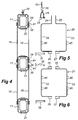
- the chains 13 as well as the steel bands 15 are attached, as is evident from Fig. 4 , to the girders 11 by enclosing holders 20, 21, of which the holder 20 is intended especially for the upper girders 11 and is shown in more detail in Fig. 5 , and the holder 21 is intended for the lower girders 11 and is shown in more detail in Fig. 6 .
- the holder 20 comprises two essentially C-shaped halves 22, 23 shaped according to the cross-sectional contour of the lattice girder 11, with the openings facing one another, said halves being made of a bent band material of steel.
- Said halves 22, 23 have lugs 24, 25 at their upper ends and lugs 26, 27 at their lower ends, which at the upper ends consist of vertically upwardly bent portions of the band material and which at the lower ends consist of tubular sleeves which are welded to the band material.
- a cotter pin 28 is moved through the lugs 24, 25 for attaching the above-mentioned chains 13, said cotter pin suitably belonging to a shackle 29, into which a hook 30 at the lower end of a chain 14 can be hooked.
- the lugs 26, 27 are preferably connected to each other by means of a locking cotter pin 31, which is moved through the tubular sleeves and then locked.
- the holder 21 also comprises two essentially C-shaped halves 32, 33 shaped according to the cross-sectional contour of the lattice girder 11, with the openings facing one another, said halves being made of a bent band material of steel.
- Said halves 32, 33 have lugs 34, 35 at their upper ends and lugs 36, 37 at their lower ends, which at both the upper and the lower ends consist of tubular sleeves which are welded to the band material.
- the lugs 34-37 are preferably connected to each other by means of locking cotter pins 38 which are moved through the tubular sleeves and then locked.
- the steel bands 15 To attach the above-mentioned steel bands 15 to the sides of the girders 11, the steel bands 15 have holes 39 formed at their ends, and both the holder 20 and the holder 21 have holes 40 formed in their sides, through which locking cotter pins 41 can be moved and then be locked.
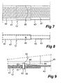
- Fig. 7 is a top plan view of a part of a telescopic plank 12
- Fig. 8 is a side view of a corresponding part
- Fig. 9 is a sectional view of a part of the plank 12 corresponding to the situation in Fig. 7 .
- the plank 12 consists of an outer and an inner mutually telescoping U section 42, 43, which have downwardly directed U openings with ends 44, 45 curved inwards, which give the telescopic plank 12 a good load-bearing capacity.
- the sections 42, 43 have a grooved anti-skid surface 46, 47 and a pullout-limiting means 48 for limiting the possible projection.
- the pullout-limiting means 48 comprises two pins 50 which are biased by means of a leaf spring 49 and which for locking are arranged to be automatically moved from the inner U section 43 through lock openings 51, 52 in the legs of the U-shaped sections 42, 43.
- the pins 50 are fixedly connected to a cable 53 which is connected to both pins 50 and thus allows simultaneous release of the two pins 50.
- the sections 42, 43, preferably the outer section 42, can also, for reasons of safety, at one end which is adapted to rest on a girder 11 have at least one vertical hole for insertion of a locking cotter pin, which is arranged to engage in a corresponding hole in the upper side of the girder 11.
Landscapes
- Engineering & Computer Science (AREA)
- Architecture (AREA)
- Civil Engineering (AREA)
- Structural Engineering (AREA)
- Mechanical Engineering (AREA)
- General Engineering & Computer Science (AREA)
- Filling Or Discharging Of Gas Storage Vessels (AREA)
- Bridges Or Land Bridges (AREA)
- Movable Scaffolding (AREA)
- Working Measures On Existing Buildindgs (AREA)
- Emergency Lowering Means (AREA)
- Load-Engaging Elements For Cranes (AREA)
- Conveying And Assembling Of Building Elements In Situ (AREA)
Abstract
Description
- The present invention relates to an apparatus for facilitating new construction and internal inspection and repair of large vessels, such as recovery boilers and tanks. The apparatus comprises a platform which is vertically adjustably suspended by means of suspension cords hanging down from a roof of the vessel, the platform being built from at least two parallel spaced-apart girders, to which the suspension cords are attached, and at least one plank being arranged perpendicular to the girders and interconnecting the same, the plank resting on the girders and at least partly covering the same.
- When large vessels, such as recovery boilers and tanks, are to be built and internally inspected and possibly repaired, the large dimensions thereof always make it necessary to use some kind of scaffold or platform, from which the work can be performed in a safe way. Then there is frequently the problem that the parts included in this scaffold or platform must be inserted through relatively small manholes in the walls or roof of the vessel. Another problem is that the above-mentioned large dimensions require the use of a large number of scaffold or platform parts so that all parts of the vessel can be reached. A further problem is that the parts inside the vessel must frequently be mounted under difficult circumstances, such as high heat inside a boiler. Finally, especially in boilers, there is also the problem that on the one hand some parts of the vessel can be difficult to reach because of what is referred to as a nose which is to be found in certain boilers, i.e. a projecting portion on one of the side walls of the boiler, and on the other hand that it may be necessary to inspect or repair superheaters which are suspended from the roof of the boiler and which between them form narrow passages.
-
US-A-5,007,501 discloses an apparatus, which is especially intended for the boiler in a thermal power station and which eliminates some of the problems occurring in the same. More specifically, a smaller number of parts are required for the known apparatus than for a traditional scaffold which is erected standing on the bottom of the large vessel. However, the mounting of the prior-art apparatus is still based on initial mounting from the bottom of the large vessel, still comprises a large number of parts that must be assembled, and does not solve all the problems of accessibility in a satisfactory manner. - Japanese Published Application
JP-A-2000-054618 US-A-5,007,501 . The apparatus according to the Japanese publication thus solves the problem with the initial mounting from the bottom of the vessel, but at the same time its applicability is limited significantly by the fact that the footboard, which is formed of said at least one plank, extends only perpendicular to the girders. This greatly limits the applicability and safety of the apparatus when, because of an obstacle, a gap must be left between two neighbouring planks. - In view hereof, the object of the invention is to improve the known apparatus according to
JP-A-2000-054618 - According to the invention, this is achieved by an apparatus of the type mentioned by way of introduction, said apparatus being characterised in that the girders are individually vertically adjustable first lattice girders, to which the suspension cords are attached and which have flat upper sides forming a footboard.
- By the apparatus according to the invention comprising individually vertically adjustable lattice girders, which have a built-in plank for walking, there is provided, in contrast to
JP-A-2000-054618 - The girders of the apparatus are preferably rectangular in cross-section, and the suspension cords are suitably attached to them by enclosing holders which enclose the respective girders and have an upper side which has a centrally arranged fastening means for each suspension cord. The advantages of girders that are rectangular in cross-section are that they have an excellent load-carrying capacity, that, if desired, they can easily be connected perpendicular to a corresponding girder of rectangular cross-section, and that outside the vessel they are stackable in an advantageous way.
- Said enclosing holders each preferably consist of two essentially C-shaped halves, with the C openings facing one another, said halves having at their upper and lower ends lugs, through which locking cotter pins are movable for locking said halves together. Thus designed holders protect in an advantageous manner the girder construction from being damaged by squeezing especially on the sides and ensure, by extending under the girder, that the entire load-carrying capacity of the girder construction can be utilised.
- Preferably, the lugs of the enclosing holders form at the upper ends said fastening means for the suspension cords. It will thus in an advantageous manner be possible to use the same locking cotter pin both for locking together the halves of the enclosing holders and for attaching a suspension cord.
- The halves of the enclosing holders are suitably made of a band material of steel bent to the cross-sectional contour of the girders. Steel has the advantage that it is very stable in shape and has great tensile strength and that it is easy to weld, which considerably facilitates the attachment of the lugs for the locking cotter pins.
- The apparatus according to the invention may, if desired, comprise at least one additional girder, which is of the same type as said first lattice girders and is suspended under at least one of those at a fixed distance. It will thus be easy to provide a platform with several storeys.
- It will be appreciated that the additional girder suitably should be rectangular in cross-section and that it is advantageous if it is suspended by enclosing holders, which enclose the girder and which are suspended from the superposed girder by means of suspension bands arranged on both sides of the girder.
- It will also be appreciated in view of that stated above that the last-mentioned enclosing holders preferably each consist of two substantially C-shaped halves, with the openings facing one another, said halves having at their upper and lower ends lugs, through which locking cotter pins are movable for locking said halves together.
- It goes without saying that also the last-mentioned enclosing holders suitably consist of halves which are made of a band material of steel which is bent to the cross-sectional contour of the additional girder.
- The suspension bands that are used for suspending an additional girder from a superposed girder are preferably steel bands, which at their ends have holes, through which locking cotter pins are movable for locking engagement in corresponding holes in the sides of the enclosing holders of the associated girders. The steel bands are also advantageous because of the good tensile strength of the steel and the fact that the holes formed therein need no extra reinforcement.
- It will be appreciated that the apparatus according to the invention can be extended further by at least one additional girder being suspended under two spaced-apart girders at a fixed distance and by at least one telescopic plank, arranged perpendicular to the girders, resting on the additional girders and interconnecting the same.
- Said at least one plank is preferably telescopic. The telescopic design makes it easier to adjust the apparatus to different conditions prevailing in the vessel.
- More specifically, the telescopic plank preferably consists of an outer and an inner mutually telescoping U section, which have downwardly directed U openings with ends curved inwards and the projection of which is limited by a pullout-limiting means. The advantage of the ends curved inwards is that they contribute to good mutual displaceability of the U sections since a point charge is avoided. The pullout-limiting means is for natural reasons necessary to prevent the two cooperating U sections from unintentionally sliding apart.
- Said pullout-limiting means suitably comprises at least one spring-biased pin, which for locking is arranged to be automatically moved from the inner U section through lock openings in the legs of the U-shaped sections. This solution has the advantage that the pin construction is well protected inside the contour of the plank, thereby facilitating the handling of the plank.
- Preferably the outer U section has, at an end which is adapted to rest on a girder, at least one vertical hole for insertion of a locking cotter pin, which is arranged to engage in a corresponding hole in the upper side of the girder. This type of securing of the plank relative to the girder is important especially for the outermost girder of a platform construction.
- The suspension cords are suitably chains hanging down from electrically operated telphers arranged on the roof of the vessel. Advantages of chains are that, in contrast to wires that are used according to
US-A-5,007,501 , they cannot be untwined and that they can be handled with greater accuracy by chain telphers than wires which are wound in layers by a wire winch. - Finally, the telphers are preferably individually remote controlled from the interior of the vessel. It will thus be easily possible to vertically adjust individual girders inside the vessel.
- A preferred embodiment of the apparatus according to the invention will in the following be described in more detail with reference to the accompanying schematic drawings, in which
-
Fig. 1 is side view with partly broken-away components and illustrates parts of a recovery boiler, in which an apparatus according to the invention is used; -
Fig. 2 is a side view and illustrates parts of the long side of a lattice girder; -
Fig. 3 is a top plan view and illustrates parts of the upper side of the lattice girder; -
Fig. 4 is an end view and illustrates three lattice girders arranged one above the other, which are interconnected by means of steel bands arranged on the sides; -
Fig. 5 is an end view and illustrates a first enclosing holder with associated locking cotter pins; -
Fig. 6 is an end view and illustrates a second enclosing holder with an associated locking cotter pin; -
Fig. 7 is a top plan view and illustrates parts of the upper side of a telescopic plank; -
Fig. 8 is a side view and illustrates parts of the long side of the telescopic plank; and -
Fig. 9 is a sectional view and illustrates parts of the upper side of the plank. -
Fig. 1 illustrates parts of a pressure vessel 1 for a recovery boiler, in which an apparatus according to the invention is used for inspection and repair purposes. However, it would be possible to use the apparatus for the same purpose also in other types of pressure vessels, such as a bark-fired boiler, or inside a vessel, such as an oil tank. Moreover, it can be used in new construction of such vessels. - The pressure vessel 1 in
Fig. 1 has, among other things,walls 2 withmanholes 3 formed therein, a so-called nose 4 mentioned by way of introduction, aprotective roof 5 and aroof 6, from which a number of superheaters 7 are suspended. - The superheater 7 constitutes one of the parts that are of special interest to be examined in connection with an inspection. However, they make such inspection difficult by forming, between them, narrow vertical passages, which may have a height of several meters and are partly positioned above the nose 4. Some of the passages extend parallel to the plane of the drawing in
Fig. 1 , and some 8 extend vertically to this plane. Themanholes 3 are preferably arranged at least at one end of thepassages 8. - The apparatus according to the invention is shown in
Fig. 1 to the right and to the left in the form of twoplatforms 10 with slightly different configurations. A common feature of the twoplatforms 10 is that the components included therein are identical since they constitute parts of a construction kit which can be extended as desired to be adjusted to the prevailing situation. - Each
platform 10 includeslattice girders 11 andtelescopic planks 12 as the main components. - Of the
girders 11, the uppermost are horizontally suspended parallel to each other both in thepassages 8 and outside the same bychains 13 hanging down fromelectric telphers 14 mounted on theroof 6 of the vessel 1. The telphers are remote controlled and can advantageously be used, for instance, in order to initially pull in a girder into the vessel 1 through asuitable manhole 3. Thelower girders 11 are suspended from the superposedgirders 11 by means ofsteel bands 15 which are arranged on both sides of thegirders 11. The suspension of both the upper and thelower girders 11 will be described in more detail below with reference toFigs 4-6 , and the construction of thegirders 11 will be discussed below with reference toFigs 2-4 . - The
telescopic planks 12 shown inFig. 1 rest ongirders 11 hanging at essentially the same level, and extend, seen from above, perpendicular to thesegirders 11. They are thus arranged perpendicular also to thepassages 8 and can therefore be used to reach the passages (those parallel to the plane of the drawing) which are perpendicular to thesepassages 8. The construction of theplanks 12 will be described in detail below with reference toFigs 7-9 . -
Fig. 2 is a side view of a part of alattice girder 11,Fig. 3 is a top plan view of a corresponding part, andFig. 4 is an end view of a plurality ofsuch girders 11. Thegirder 11, which is rectangular in cross-section, is made of aluminium and comprises four longitudinalmain pipes 16 arranged in the cross-sectional corners. A grid structure of thinner pipes orrods 17, which stabilises themain pipes 16, extends between thesemain pipes 16 in a zigzag. On top of the two uppermain pipes 16, afootboard plate 18 is attached, which has a grooved anti-skidupper side 19. At the ends of thegirder 11, coupling means (not shown) of prior-art type can be arranged for a possible extension of thegirder 11 or for connection of a ladder for instance. - For suspension of the
girders 11, use is made, as stated above, ofchains 13 for theupper girders 11 andsteel bands 15 for thelower girders 11. Thechains 13 as well as thesteel bands 15 are attached, as is evident fromFig. 4 , to thegirders 11 by enclosingholders holder 20 is intended especially for theupper girders 11 and is shown in more detail inFig. 5 , and theholder 21 is intended for thelower girders 11 and is shown in more detail inFig. 6 . - The
holder 20 comprises two essentially C-shapedhalves lattice girder 11, with the openings facing one another, said halves being made of a bent band material of steel. Said halves 22, 23 havelugs cotter pin 28 is moved through thelugs chains 13, said cotter pin suitably belonging to ashackle 29, into which ahook 30 at the lower end of achain 14 can be hooked. At the lower ends, the lugs 26, 27 are preferably connected to each other by means of a lockingcotter pin 31, which is moved through the tubular sleeves and then locked. - The
holder 21 also comprises two essentially C-shapedhalves lattice girder 11, with the openings facing one another, said halves being made of a bent band material of steel. Said halves 32, 33 havelugs cotter pins 38 which are moved through the tubular sleeves and then locked. - To attach the above-mentioned
steel bands 15 to the sides of thegirders 11, thesteel bands 15 haveholes 39 formed at their ends, and both theholder 20 and theholder 21 haveholes 40 formed in their sides, through which lockingcotter pins 41 can be moved and then be locked. -
Fig. 7 is a top plan view of a part of atelescopic plank 12,Fig. 8 is a side view of a corresponding part, andFig. 9 is a sectional view of a part of theplank 12 corresponding to the situation inFig. 7 . Theplank 12 consists of an outer and an inner mutually telescopingU section ends sections anti-skid surface means 48 for limiting the possible projection. - The pullout-limiting
means 48 comprises twopins 50 which are biased by means of aleaf spring 49 and which for locking are arranged to be automatically moved from theinner U section 43 throughlock openings U-shaped sections pins 50 are fixedly connected to a cable 53 which is connected to bothpins 50 and thus allows simultaneous release of the twopins 50. - The
sections outer section 42, can also, for reasons of safety, at one end which is adapted to rest on agirder 11 have at least one vertical hole for insertion of a locking cotter pin, which is arranged to engage in a corresponding hole in the upper side of thegirder 11. - A person skilled in the art will realise that the above-described embodiment of the invention may be varied in many ways within the scope of the claims, and that the above-described
platforms 10, depending on the number ofplanks 12 that are arranged and the number ofgirders 11 arranged under and next to each other are usable for most operations which are to be performed in the vessels at issue and in which a scaffold is required.
Claims (17)
- An apparatus for facilitating new construction as well as internal inspection and repair of large vessels (1), such as recovery boilers and tanks, said apparatus comprising a platform (10) which is vertically adjustably suspended by means of suspension cords (13) hanging down from a roof (6) of the vessel (1), the platform (10) being built from at least two parallel spaced-apart girders (11), to which the suspension cords (13) are attached, and at least one plank (12) being arranged perpendicular to the girders (11) and interconnecting the same, the plank resting on the girders (11) and at least partly covering the same, characterised in that the girders (11) are individually vertically adjustable first lattice girders (11), to which the suspension cords (13) are attached and which have flat upper sides forming a footboard (18).
- An apparatus as claimed in claim 1, characterised in that the girders (11) are rectangular in cross-section, and that the suspension cords (13) are attached thereto by enclosing holders (20) which enclose the respective girders (11) and have an upper side which has a centrally arranged fastening means (24, 25) for each suspension cord (13).
- An apparatus as claimed in claim 2, characterised in that the enclosing holders (20) each consist of two essentially C-shaped halves (22, 23), with the C openings facing one other, said halves having at their upper and lower ends lugs (24-27), through which locking cotter pins (28-31) are movable for locking said halves (22, 23) together.
- An apparatus as claimed in claim 3, characterised in that the lugs (24, 25) at the upper ends form said fastening means.
- An apparatus as claimed in claim 3 or 4, characterised in that said halves (22, 23) are made of a band material of steel bent to the cross-sectional contour of the girders (11).
- An apparatus as claimed in any one of claims 1-5, characterised in that at least one additional girder (11), which is of the same type as said first lattice girders (11), is suspended under at least one of those at a fixed distance.
- An apparatus as claimed in claim 6, characterised in that the additional girder (11) is rectangular in cross-section, and that it is suspended by enclosing holders (21) which enclose the girder and which are suspended from the superposed girder (11) by means of suspension bands (15) arranged on both sides of the girder (11).
- An apparatus as claimed in claim 7, characterised in that the enclosing holders (21) each consist of two essentially C-shaped halves (32, 33), with the openings facing one another, said halves having at their upper and lower ends lugs (34-37), through which locking cotter pins (38) are movable for locking said halves (32, 33) together.
- An apparatus as claimed in claim 7 or 8, characterised in that said halves (32, 33) are made of a band material of steel bent to the cross-sectional contour of the additional girder (11).
- An apparatus as claimed in any one of claims 2-5 and any one of claims 6-8, characterised in that the suspension bands are steel bands (15), which at their ends have holes (39), through which locking cotter pins (41) are movable for locking engagement in corresponding holes (40) in the sides of the enclosing holders (20, 21) of the associated girders (11).
- An apparatus as claimed in any one of claims 6-10, characterised in that at least one additional girder (11) is suspended under two spaced-apart girders (11) at a fixed distance, and that at least one plank (12) is arranged perpendicular to the girders (11) and interconnecting the girders (11), said plank resting on the additional girders (11) and at least partly covering the same.
- An apparatus as claimed in any one of claims 1-11, characterised in that said at least one plank (12) is telescopic.
- An apparatus as claimed in claim 12, characterised in that the telescopic plank (12) consists of an outer and an inner mutually telescoping U section (42, 43), which have downwardly directed U openings with ends (44, 45) curved inwards and the projection of which is limited by a pullout-limiting means (48).
- An apparatus as claimed in claim 13, characterised in that the pullout-limiting means (48) comprises at least one spring-biased pin (50), which for locking is arranged to be automatically moved from the inner U section (43) through lock openings (51, 52) in the legs of the U-shaped sections (42, 43).
- An apparatus as claimed in claim 13 or 14, characterised in that the outer U section (42) at an end which is adapted to rest on a girder (11) has at least one vertical hole for insertion of a locking cotter pin, which is arranged to engage in a corresponding hole in the upper side of the girder (11).
- An apparatus as claimed in any one of claims 1-15, characterised in that the suspension cords are chains (13) hanging down from electrically operated telphers (14) which are arranged on the roof (6) of the vessel (1).
- An apparatus as claimed in claim 16, characterised in that the telphers (14) are individually remote controlled from the interior of the vessel (1).
Applications Claiming Priority (2)
| Application Number | Priority Date | Filing Date | Title |
|---|---|---|---|
| SE0302639A SE525265C2 (en) | 2003-10-06 | 2003-10-06 | Construction, inspection and repair device for e.g. recovery boiler, comprises platform suspended on cables from vessel roof and assembled from beams and trusses |
| PCT/SE2004/001420 WO2005033441A1 (en) | 2003-10-06 | 2004-10-06 | Apparatus for faciliating new construction and the internal inspection and repair of large vessels, such as recovery boilers and tanks |
Publications (2)
| Publication Number | Publication Date |
|---|---|
| EP1685302A1 EP1685302A1 (en) | 2006-08-02 |
| EP1685302B1 true EP1685302B1 (en) | 2010-02-24 |
Family
ID=29398664
Family Applications (1)
| Application Number | Title | Priority Date | Filing Date |
|---|---|---|---|
| EP04775511A Expired - Lifetime EP1685302B1 (en) | 2003-10-06 | 2004-10-06 | Apparatus for faciliating new construction and the internal inspection and repair of large vessels, such as recovery boilers and tanks |
Country Status (16)
| Country | Link |
|---|---|
| US (1) | US20070209872A1 (en) |
| EP (1) | EP1685302B1 (en) |
| JP (1) | JP2007507632A (en) |
| KR (1) | KR20070004534A (en) |
| CN (1) | CN100416019C (en) |
| AT (1) | ATE458878T1 (en) |
| AU (1) | AU2004277575A1 (en) |
| BR (1) | BRPI0415080A (en) |
| CA (1) | CA2541062A1 (en) |
| DE (1) | DE602004025725D1 (en) |
| DK (1) | DK1685302T3 (en) |
| EA (1) | EA008309B1 (en) |
| NO (1) | NO20061484L (en) |
| SE (1) | SE525265C2 (en) |
| WO (1) | WO2005033441A1 (en) |
| ZA (1) | ZA200602794B (en) |
Families Citing this family (3)
| Publication number | Priority date | Publication date | Assignee | Title |
|---|---|---|---|---|
| US10451269B2 (en) * | 2016-03-21 | 2019-10-22 | General Electric Company | System and method for supporting a boiler load |
| CN107490004B (en) * | 2017-08-20 | 2019-10-11 | 福建俊佑机电设备有限公司 | Power plant boiler central cylinder of separator remodeling method |
| US10926599B2 (en) * | 2017-12-01 | 2021-02-23 | Divergent Technologies, Inc. | Suspension systems using hydraulic dampers |
Family Cites Families (4)
| Publication number | Priority date | Publication date | Assignee | Title |
|---|---|---|---|---|
| US4058184A (en) * | 1976-04-15 | 1977-11-15 | Hugh J. Baker & Company | Scaffold |
| US4474497A (en) * | 1983-04-14 | 1984-10-02 | Combustion Engineering, Inc. | Furnace maintenance platform |
| US5007501A (en) * | 1989-09-01 | 1991-04-16 | Baston Peter J | Apparatus for facilitating the internal inspection and repair of large pressure vessels |
| JP2000054618A (en) * | 1998-07-31 | 2000-02-22 | Koyo Kikai Sangyo Kk | Connection structure of girder members in suspension scaffold, press support structure of erected scaffold plate, and scaffold plate |
-
2003
- 2003-10-06 SE SE0302639A patent/SE525265C2/en not_active IP Right Cessation
-
2004
- 2004-10-06 BR BRPI0415080-5A patent/BRPI0415080A/en not_active Application Discontinuation
- 2004-10-06 EP EP04775511A patent/EP1685302B1/en not_active Expired - Lifetime
- 2004-10-06 AU AU2004277575A patent/AU2004277575A1/en not_active Abandoned
- 2004-10-06 KR KR1020067008875A patent/KR20070004534A/en not_active Withdrawn
- 2004-10-06 DK DK04775511.1T patent/DK1685302T3/en active
- 2004-10-06 ZA ZA200602794A patent/ZA200602794B/en unknown
- 2004-10-06 DE DE602004025725T patent/DE602004025725D1/en not_active Expired - Lifetime
- 2004-10-06 EA EA200600674A patent/EA008309B1/en not_active IP Right Cessation
- 2004-10-06 CA CA002541062A patent/CA2541062A1/en not_active Abandoned
- 2004-10-06 US US10/574,708 patent/US20070209872A1/en not_active Abandoned
- 2004-10-06 CN CNB2004800293149A patent/CN100416019C/en not_active Expired - Fee Related
- 2004-10-06 JP JP2006532234A patent/JP2007507632A/en active Pending
- 2004-10-06 AT AT04775511T patent/ATE458878T1/en not_active IP Right Cessation
- 2004-10-06 WO PCT/SE2004/001420 patent/WO2005033441A1/en not_active Ceased
-
2006
- 2006-03-31 NO NO20061484A patent/NO20061484L/en not_active Application Discontinuation
Also Published As
| Publication number | Publication date |
|---|---|
| CA2541062A1 (en) | 2005-04-14 |
| JP2007507632A (en) | 2007-03-29 |
| WO2005033441A1 (en) | 2005-04-14 |
| EA200600674A1 (en) | 2006-08-25 |
| DE602004025725D1 (en) | 2010-04-08 |
| BRPI0415080A (en) | 2006-12-12 |
| ATE458878T1 (en) | 2010-03-15 |
| SE0302639L (en) | 2005-01-18 |
| NO20061484L (en) | 2006-07-06 |
| ZA200602794B (en) | 2007-07-25 |
| CN100416019C (en) | 2008-09-03 |
| CN1863977A (en) | 2006-11-15 |
| DK1685302T3 (en) | 2010-06-14 |
| SE525265C2 (en) | 2005-01-18 |
| US20070209872A1 (en) | 2007-09-13 |
| SE0302639D0 (en) | 2003-10-06 |
| EP1685302A1 (en) | 2006-08-02 |
| AU2004277575A1 (en) | 2005-04-14 |
| KR20070004534A (en) | 2007-01-09 |
| EA008309B1 (en) | 2007-04-27 |
Similar Documents
| Publication | Publication Date | Title |
|---|---|---|
| EP3095750B1 (en) | Method for inspecting an inside room of a ship and/or performing works therein | |
| US4071988A (en) | Core and beam suspension system for a building construction and method of construction | |
| US7726447B2 (en) | Inspection scaffold of large component for boiler and building method thereof | |
| JP5097313B2 (en) | Suspended scaffold and its installation method | |
| US10260284B2 (en) | Ladder installation for equipment tower | |
| US4382488A (en) | Pump jack poles | |
| US6425712B1 (en) | Method and apparatus for providing lateral support to a post | |
| CN118855211B (en) | A method for installing a suspended platform | |
| CN212773371U (en) | Limited space steel construction daylighting top cable work platform | |
| US20070209872A1 (en) | Apparatus for facilitating new construction and the internal inspection and repair of large vessels, such as recovery boilers and tanks | |
| CN108118885B (en) | vertical moving type protection platform and application thereof in steel structure column butt joint construction | |
| CN215331283U (en) | Combined splicing type liftable protective tower | |
| JP6783011B1 (en) | Suspended scaffolding | |
| CN113389363A (en) | Combined splicing type liftable protective tower | |
| CN114776035B (en) | Construction method of oblique spoke type cable truss structure | |
| JP6842738B1 (en) | Suspended scaffolding | |
| CN113503011B (en) | Installation and use method of cableway hanging basket structure for curtain wall construction at the bottom of steel structure corridor | |
| GB2311321A (en) | Access work platform | |
| CN116816067B (en) | Ship section ladder and its use method | |
| GB2152992A (en) | Collapsible scaffolding having supply lines or guide rails or handrails | |
| CN215594839U (en) | Station auxiliary device applied to super high-rise steel-concrete structure | |
| CN217556698U (en) | Bridge boundary beam hogging moment stretch-draw construction platform | |
| CN223561231U (en) | Maintenance platform for suspension crane | |
| KR101323384B1 (en) | Remote Erecting Suspended Scaffolding and the methods | |
| WO2022128038A1 (en) | Cable protection system |
Legal Events
| Date | Code | Title | Description |
|---|---|---|---|
| PUAI | Public reference made under article 153(3) epc to a published international application that has entered the european phase |
Free format text: ORIGINAL CODE: 0009012 |
|
| 17P | Request for examination filed |
Effective date: 20060424 |
|
| AK | Designated contracting states |
Kind code of ref document: A1 Designated state(s): AT BE BG CH CY CZ DE DK EE ES FI FR GB GR HU IE IT LI LU MC NL PL PT RO SE SI SK TR |
|
| AX | Request for extension of the european patent |
Extension state: LT LV |
|
| RAX | Requested extension states of the european patent have changed |
Extension state: LT Payment date: 20060424 Extension state: LV Payment date: 20060424 |
|
| GRAP | Despatch of communication of intention to grant a patent |
Free format text: ORIGINAL CODE: EPIDOSNIGR1 |
|
| GRAS | Grant fee paid |
Free format text: ORIGINAL CODE: EPIDOSNIGR3 |
|
| GRAA | (expected) grant |
Free format text: ORIGINAL CODE: 0009210 |
|
| AK | Designated contracting states |
Kind code of ref document: B1 Designated state(s): AT BE BG CH CY CZ DE DK EE ES FI FR GB GR HU IE IT LI LU MC NL PL PT RO SE SI SK TR |
|
| AX | Request for extension of the european patent |
Extension state: LT LV |
|
| REG | Reference to a national code |
Ref country code: GB Ref legal event code: FG4D |
|
| REG | Reference to a national code |
Ref country code: CH Ref legal event code: EP |
|
| REG | Reference to a national code |
Ref country code: IE Ref legal event code: FG4D |
|
| REF | Corresponds to: |
Ref document number: 602004025725 Country of ref document: DE Date of ref document: 20100408 Kind code of ref document: P |
|
| REG | Reference to a national code |
Ref country code: DK Ref legal event code: T3 |
|
| REG | Reference to a national code |
Ref country code: NL Ref legal event code: VDEP Effective date: 20100224 |
|
| LTIE | Lt: invalidation of european patent or patent extension |
Effective date: 20100224 |
|
| PG25 | Lapsed in a contracting state [announced via postgrant information from national office to epo] |
Ref country code: PT Free format text: LAPSE BECAUSE OF FAILURE TO SUBMIT A TRANSLATION OF THE DESCRIPTION OR TO PAY THE FEE WITHIN THE PRESCRIBED TIME-LIMIT Effective date: 20100625 |
|
| PG25 | Lapsed in a contracting state [announced via postgrant information from national office to epo] |
Ref country code: AT Free format text: LAPSE BECAUSE OF FAILURE TO SUBMIT A TRANSLATION OF THE DESCRIPTION OR TO PAY THE FEE WITHIN THE PRESCRIBED TIME-LIMIT Effective date: 20100224 Ref country code: PL Free format text: LAPSE BECAUSE OF FAILURE TO SUBMIT A TRANSLATION OF THE DESCRIPTION OR TO PAY THE FEE WITHIN THE PRESCRIBED TIME-LIMIT Effective date: 20100224 Ref country code: SI Free format text: LAPSE BECAUSE OF FAILURE TO SUBMIT A TRANSLATION OF THE DESCRIPTION OR TO PAY THE FEE WITHIN THE PRESCRIBED TIME-LIMIT Effective date: 20100224 |
|
| PG25 | Lapsed in a contracting state [announced via postgrant information from national office to epo] |
Ref country code: GR Free format text: LAPSE BECAUSE OF FAILURE TO SUBMIT A TRANSLATION OF THE DESCRIPTION OR TO PAY THE FEE WITHIN THE PRESCRIBED TIME-LIMIT Effective date: 20100525 Ref country code: SE Free format text: LAPSE BECAUSE OF FAILURE TO SUBMIT A TRANSLATION OF THE DESCRIPTION OR TO PAY THE FEE WITHIN THE PRESCRIBED TIME-LIMIT Effective date: 20100224 Ref country code: RO Free format text: LAPSE BECAUSE OF FAILURE TO SUBMIT A TRANSLATION OF THE DESCRIPTION OR TO PAY THE FEE WITHIN THE PRESCRIBED TIME-LIMIT Effective date: 20100224 Ref country code: NL Free format text: LAPSE BECAUSE OF FAILURE TO SUBMIT A TRANSLATION OF THE DESCRIPTION OR TO PAY THE FEE WITHIN THE PRESCRIBED TIME-LIMIT Effective date: 20100224 Ref country code: BE Free format text: LAPSE BECAUSE OF FAILURE TO SUBMIT A TRANSLATION OF THE DESCRIPTION OR TO PAY THE FEE WITHIN THE PRESCRIBED TIME-LIMIT Effective date: 20100224 Ref country code: CY Free format text: LAPSE BECAUSE OF FAILURE TO SUBMIT A TRANSLATION OF THE DESCRIPTION OR TO PAY THE FEE WITHIN THE PRESCRIBED TIME-LIMIT Effective date: 20100224 Ref country code: EE Free format text: LAPSE BECAUSE OF FAILURE TO SUBMIT A TRANSLATION OF THE DESCRIPTION OR TO PAY THE FEE WITHIN THE PRESCRIBED TIME-LIMIT Effective date: 20100224 Ref country code: ES Free format text: LAPSE BECAUSE OF FAILURE TO SUBMIT A TRANSLATION OF THE DESCRIPTION OR TO PAY THE FEE WITHIN THE PRESCRIBED TIME-LIMIT Effective date: 20100604 |
|
| PG25 | Lapsed in a contracting state [announced via postgrant information from national office to epo] |
Ref country code: CZ Free format text: LAPSE BECAUSE OF FAILURE TO SUBMIT A TRANSLATION OF THE DESCRIPTION OR TO PAY THE FEE WITHIN THE PRESCRIBED TIME-LIMIT Effective date: 20100224 Ref country code: BG Free format text: LAPSE BECAUSE OF FAILURE TO SUBMIT A TRANSLATION OF THE DESCRIPTION OR TO PAY THE FEE WITHIN THE PRESCRIBED TIME-LIMIT Effective date: 20100524 Ref country code: SK Free format text: LAPSE BECAUSE OF FAILURE TO SUBMIT A TRANSLATION OF THE DESCRIPTION OR TO PAY THE FEE WITHIN THE PRESCRIBED TIME-LIMIT Effective date: 20100224 |
|
| PLBE | No opposition filed within time limit |
Free format text: ORIGINAL CODE: 0009261 |
|
| STAA | Information on the status of an ep patent application or granted ep patent |
Free format text: STATUS: NO OPPOSITION FILED WITHIN TIME LIMIT |
|
| PGFP | Annual fee paid to national office [announced via postgrant information from national office to epo] |
Ref country code: DK Payment date: 20101027 Year of fee payment: 7 |
|
| 26N | No opposition filed |
Effective date: 20101125 |
|
| PGFP | Annual fee paid to national office [announced via postgrant information from national office to epo] |
Ref country code: DE Payment date: 20101103 Year of fee payment: 7 Ref country code: FI Payment date: 20101027 Year of fee payment: 7 |
|
| PG25 | Lapsed in a contracting state [announced via postgrant information from national office to epo] |
Ref country code: IT Free format text: LAPSE BECAUSE OF FAILURE TO SUBMIT A TRANSLATION OF THE DESCRIPTION OR TO PAY THE FEE WITHIN THE PRESCRIBED TIME-LIMIT Effective date: 20100224 |
|
| PGFP | Annual fee paid to national office [announced via postgrant information from national office to epo] |
Ref country code: GB Payment date: 20101103 Year of fee payment: 7 |
|
| PG25 | Lapsed in a contracting state [announced via postgrant information from national office to epo] |
Ref country code: MC Free format text: LAPSE BECAUSE OF NON-PAYMENT OF DUE FEES Effective date: 20101031 |
|
| REG | Reference to a national code |
Ref country code: CH Ref legal event code: PL |
|
| PG25 | Lapsed in a contracting state [announced via postgrant information from national office to epo] |
Ref country code: LI Free format text: LAPSE BECAUSE OF NON-PAYMENT OF DUE FEES Effective date: 20101031 Ref country code: CH Free format text: LAPSE BECAUSE OF NON-PAYMENT OF DUE FEES Effective date: 20101031 Ref country code: FR Free format text: LAPSE BECAUSE OF NON-PAYMENT OF DUE FEES Effective date: 20101102 |
|
| REG | Reference to a national code |
Ref country code: FR Ref legal event code: ST Effective date: 20110630 |
|
| PG25 | Lapsed in a contracting state [announced via postgrant information from national office to epo] |
Ref country code: IE Free format text: LAPSE BECAUSE OF NON-PAYMENT OF DUE FEES Effective date: 20101006 |
|
| GBPC | Gb: european patent ceased through non-payment of renewal fee |
Effective date: 20111006 |
|
| REG | Reference to a national code |
Ref country code: DK Ref legal event code: EBP |
|
| PG25 | Lapsed in a contracting state [announced via postgrant information from national office to epo] |
Ref country code: DE Free format text: LAPSE BECAUSE OF NON-PAYMENT OF DUE FEES Effective date: 20120501 |
|
| REG | Reference to a national code |
Ref country code: DE Ref legal event code: R119 Ref document number: 602004025725 Country of ref document: DE Effective date: 20120501 |
|
| PG25 | Lapsed in a contracting state [announced via postgrant information from national office to epo] |
Ref country code: FI Free format text: LAPSE BECAUSE OF NON-PAYMENT OF DUE FEES Effective date: 20111006 Ref country code: GB Free format text: LAPSE BECAUSE OF NON-PAYMENT OF DUE FEES Effective date: 20111006 |
|
| PG25 | Lapsed in a contracting state [announced via postgrant information from national office to epo] |
Ref country code: LU Free format text: LAPSE BECAUSE OF NON-PAYMENT OF DUE FEES Effective date: 20101006 Ref country code: HU Free format text: LAPSE BECAUSE OF FAILURE TO SUBMIT A TRANSLATION OF THE DESCRIPTION OR TO PAY THE FEE WITHIN THE PRESCRIBED TIME-LIMIT Effective date: 20100825 |
|
| PG25 | Lapsed in a contracting state [announced via postgrant information from national office to epo] |
Ref country code: DK Free format text: LAPSE BECAUSE OF NON-PAYMENT OF DUE FEES Effective date: 20111031 Ref country code: TR Free format text: LAPSE BECAUSE OF FAILURE TO SUBMIT A TRANSLATION OF THE DESCRIPTION OR TO PAY THE FEE WITHIN THE PRESCRIBED TIME-LIMIT Effective date: 20100224 |