EP1684925B1 - Pass-through gage and method of gaging a workpiece - Google Patents
Pass-through gage and method of gaging a workpiece Download PDFInfo
- Publication number
- EP1684925B1 EP1684925B1 EP04811471A EP04811471A EP1684925B1 EP 1684925 B1 EP1684925 B1 EP 1684925B1 EP 04811471 A EP04811471 A EP 04811471A EP 04811471 A EP04811471 A EP 04811471A EP 1684925 B1 EP1684925 B1 EP 1684925B1
- Authority
- EP
- European Patent Office
- Prior art keywords
- workpiece
- gage
- gaging
- assembly
- gage assembly
- Prior art date
- Legal status (The legal status is an assumption and is not a legal conclusion. Google has not performed a legal analysis and makes no representation as to the accuracy of the status listed.)
- Expired - Lifetime
Links
- 230000033001 locomotion Effects 0.000 claims description 20
- 238000000034 method Methods 0.000 claims description 11
- 239000006096 absorbing agent Substances 0.000 claims description 5
- 230000035939 shock Effects 0.000 claims description 5
- 239000000463 material Substances 0.000 claims description 3
- 238000005259 measurement Methods 0.000 description 7
- 239000000523 sample Substances 0.000 description 7
- 230000005540 biological transmission Effects 0.000 description 5
- 230000008569 process Effects 0.000 description 5
- 125000006850 spacer group Chemical group 0.000 description 5
- 238000010276 construction Methods 0.000 description 4
- 230000000712 assembly Effects 0.000 description 3
- 238000000429 assembly Methods 0.000 description 3
- 230000007423 decrease Effects 0.000 description 3
- 230000008878 coupling Effects 0.000 description 2
- 238000010168 coupling process Methods 0.000 description 2
- 238000005859 coupling reaction Methods 0.000 description 2
- 238000005516 engineering process Methods 0.000 description 2
- 230000005484 gravity Effects 0.000 description 2
- 238000003754 machining Methods 0.000 description 2
- 238000004519 manufacturing process Methods 0.000 description 2
- 239000004698 Polyethylene Substances 0.000 description 1
- 238000004458 analytical method Methods 0.000 description 1
- 230000008859 change Effects 0.000 description 1
- 230000002950 deficient Effects 0.000 description 1
- 230000001934 delay Effects 0.000 description 1
- 230000002542 deteriorative effect Effects 0.000 description 1
- 238000006073 displacement reaction Methods 0.000 description 1
- 230000001747 exhibiting effect Effects 0.000 description 1
- 238000007667 floating Methods 0.000 description 1
- 230000007246 mechanism Effects 0.000 description 1
- 230000004048 modification Effects 0.000 description 1
- 238000012986 modification Methods 0.000 description 1
- -1 polyethylene Polymers 0.000 description 1
- 229920000573 polyethylene Polymers 0.000 description 1
- 230000008439 repair process Effects 0.000 description 1
- 230000004044 response Effects 0.000 description 1
- 230000000284 resting effect Effects 0.000 description 1
- 230000003068 static effect Effects 0.000 description 1
Images

Classifications
-
- G—PHYSICS
- G01—MEASURING; TESTING
- G01B—MEASURING LENGTH, THICKNESS OR SIMILAR LINEAR DIMENSIONS; MEASURING ANGLES; MEASURING AREAS; MEASURING IRREGULARITIES OF SURFACES OR CONTOURS
- G01B5/00—Measuring arrangements characterised by the use of mechanical techniques
- G01B5/003—Measuring of motor parts
-
- G—PHYSICS
- G01—MEASURING; TESTING
- G01B—MEASURING LENGTH, THICKNESS OR SIMILAR LINEAR DIMENSIONS; MEASURING ANGLES; MEASURING AREAS; MEASURING IRREGULARITIES OF SURFACES OR CONTOURS
- G01B5/00—Measuring arrangements characterised by the use of mechanical techniques
- G01B5/08—Measuring arrangements characterised by the use of mechanical techniques for measuring diameters
-
- G—PHYSICS
- G01—MEASURING; TESTING
- G01B—MEASURING LENGTH, THICKNESS OR SIMILAR LINEAR DIMENSIONS; MEASURING ANGLES; MEASURING AREAS; MEASURING IRREGULARITIES OF SURFACES OR CONTOURS
- G01B5/00—Measuring arrangements characterised by the use of mechanical techniques
- G01B5/08—Measuring arrangements characterised by the use of mechanical techniques for measuring diameters
- G01B5/10—Measuring arrangements characterised by the use of mechanical techniques for measuring diameters of objects while moving
Definitions
- the present invention generally relates to the gaging of workpieces and more particularly to a gage designed to measure multiple diameters on a workpiece without the need for special part fixturing. As such, it is particularly useful as a post-process gage after a workpiece has been ground in an infeed centerless grinding process or other grinding process.
- spool valves found in automotive transmissions. These spool valves are generally cylindrical in shape and include a series of raised and recessed lands formed thereon. The dimensions of these raised lands are critical since the valves slide within precisely dimensioned bores within the transmission assembly itself. If the lands are not properly dimensioned, performance of the transmission assembly may suffer or the transmission assembly may fail. Since a specific spool valve would be utilized in a large number of vehicles, should the manufacturing line machining these spool valves be in error, the end result is a large number of defective transmission assemblies.
- the current practice is to individually gage each and every spool valve.
- the spool valve In gaging these parts, the spool valve is delivered to a gage assembly where the workpiece is fixtured and, then, an analysis of its dimensions is performed. After gauging, the spool valve is removed from the fixture and either passed through to an accepted parts bin or a rejected parts bin. If a series of parts deviating from the desired dimension are found to exist from a particular grinding station, then the grinding station can be identified for appropriate adjustment (automatic or manual) or for repairs.
- US 4,528,651 discloses a method and apparatus for measuring the length and height of objects.
- the object is first measured for length in a first measurement station and is then advanced under a transverse array of echo ranging transducers.
- the transducer most closely to the center of the object is utilized and a microprocessor selects the measurement indicating the shortest distance between the object and the transducer as the measurement.
- EP 1 067 360 A1 discloses a system for evaluating the geometry of articles on a conveyor. An end of a feeler tracks the exposed surface of the article as it is moved by the feeler on a conveyor. A means for measuring the position of the end of the feeler relative to a frame and a means for calculating the geometery of the part based on measured position of the feeler are also disclosed.
- US 5,643,049 discloses a floating contact gage for measuring cylindrical workpieces.
- the gage is mounted for movement so as to track along the longitudinal axis of a moving workpiece as it is moved along a path of travel from a grinder.
- the present invention provides a gage where the workpiece enters the gage via an inclined chute, allowing the workpiece to slide along the chute by gravity or other means.
- the workpiece comes to a rest on a shallow V-block.
- the workpiece is detected by a proximity sensor located at the low end of the V-block.
- a part handling slide with approximately shaped soft tooling, pushes or pulls the workpiece laterally from the V-block, onto a raised support surface of a support member and passes the workpiece through the gage.
- the workpiece is continuously moved or passed through the gage by the slide. As the workpiece is being passed through the gage, readings of the workpiece's diameter in one or more, and preferably at least two, locations are taken.
- the gage itself includes carbide rails provided at two locations under the part. The locations are chosen to support the part near each end.
- a gage block subassembly is spaced above and may be located so as to oppose the rails at each location.
- Each gage block subassembly includes a pivoting contact backed by a common pencil probe. The gage block subassembly produces diameter readings at each location as the workpiece passes between the rails and thereby contacts and affects displacement of the contact and the probe. Peak values at each location are recorded by the software in the gage electronics to determine the desired attributes of the workpiece.
- the gage fixture itself includes two or more of the gage block subassemblies located opposite the support rails.
- the gage block subassemblies are assembled into the fixture at the desired locations with a series of appropriately sized shims that are sized and spaced to create a gage assembly that matches the geometry or desired location of measurement of the workpiece.
- These same shims also support a pivot shaft that is common to all of the pivoting contacts of all the gage block subassemblies.
- the entire stack of shims and gage block subassemblies are held together by drawbolts that pass through the assembly from end plates located at each end of the stack. The end plates could also support the carbide rails.
- Each gage block subassembly has an adjustable spring to set the force exerted by the contact to a value that stabilizes the workpiece precisely as it is passed through the gage. With the part so stabilized, it is also possible to place, as suggested above, additional gage block subassemblies at locations other than those directly opposing the rails. These additional gage block subassemblies will also generate useful diameter readings that may be used to verify the amount of taper, hourglass, or barrel profile that may exist along the part. It is noted that this can only be achieved by assuming certain attributes of the workpieces processed by the grinding process. Specifically, the runout and out of round values must be small in relationship to the diameter tolerance being measured.
- the gages located at some distance from either of the two support rails are actually measuring the radial distance from the true centerline of the part as it sits on the rails. Because of this, the gage electronics must compensate these readings by a factor generated from the geometric information obtained by the two gages opposing the support rails. For instance, if both support diameters fall near the minimum workpiece size tolerance, the actual centerline of the workpiece will pass through the gage at a height lower than that of a mean sized part by an amount equal to half of this tolerance. All the gages that have no support rail under them must be compensated by this amount to arrive at a true reading. The gage electronic software can readily accomplish this task if the accuracy of the application requires it.
- gage assembly 10 embodying the principles of the present invention and generally designated at 10.
- the gage assembly 10 includes as its primary components a part handling slide 12 and an actuator 14.
- the actuator 14 and part handling slide 12 cooperate with each other to cause movement of a workpiece 16 through a pair of gage block subassemblies 18 where readings of the workpiece's diameter in one or more, and preferably at least two, locations is taken.
- the workpiece is at times only illustrated as a cylindrical workpiece. Such a depiction of the workpiece 16 is seen in Figure 2 . At other times, the workpiece 16 is depicted as a spool valve having a series of raised lands 20 and recessed lands 22. In that the dimension of the raised lands 20 is critical to the operation of the spool valve 16, the diameter of the raised lands 20, preferably of least two of the raised lands 20, is the critical dimension measured by the gage assembly 10. Additionally, in certain figures portions of the gage assembly 10 is omitted for clarity.
- the workpiece 16 is provided to the gage assembly 10 by a workpiece delivery means such as an inclined chute allowing the workpiece 16 to slide, under the influence of gravity, to the gage assembly 10.
- a workpiece delivery means such as an inclined chute allowing the workpiece 16 to slide, under the influence of gravity, to the gage assembly 10.
- the workpiece 16 is received into a vee-block 24.
- the vee-block 24 has defined therein a shallow recess 26 that is in the shape of a "v".
- the recess 26 may be provided with alternative shapes.
- the recess 26 extends the width of the vee-block 24 and may be inclined along its length, from one end of the recess 26 to the other, so as to insure that the workpiece 16 is fully received onto the upper surface 28 of the vee-block 24.
- At least two supports 30 are also provided in the vee-block 24.
- the location of the supports 30 are preferably chosen so that they support the workpiece 16 near the ends thereof. Additionally, the supports 30 define the locations in which, at a minimum, measurements of the workpiece 16 will be taken.
- the supports 30 themselves are in the form of rails received in mounting blocks, and the rails are preferably constructed of a material exhibiting extremely low wear characteristics.
- One preferred material is carbide.
- the uppermost surface of the supports 30 are provided such that these surfaces of the supports 30 are elevated relative the upper surface 28 of the vee-block 24. This is readily seen in Figures 5 and 7 .
- the part handling slide is constructed of a soft tooling, for example polyethylene, and is coupled to the actuator 14 so as to be moveable in a direction generally transverse to the length or longitudinal axis of the recess 26 formed in the vee-block 24.
- the direction of movement of the part handling slide 12 is in the direction of the longitudinal axis of the supports 30, which is transverse to the longitudinal axis of the workpiece 16.
- the part handling slide 12 rests generally above or on the upper surface 28 of the vee-block 24 and is moveable thereacross as a result of the advancement of the connector rods 32 of the actuator 14.
- the actuator 14 may be any variety of actuator heretofore or hereafter devised.
- the actuator 14 is a pneumatic actuator coupled to a pneumatic source 34 via a coupling line 36.
- the actuator 14 similarly causes retraction of the part handling slide 12 as is conventionally known to be done.
- the receipt of the workpiece 16 is detected by a proximity sensor 38 appropriately positioned with respect to the end of the recess 26 in the vee-block 24.
- the proximity sensor 38 provides a signal indicating the presence of a workpiece 16 to a controller 40, which in turn causes advancement of the actuator and the part handling slide 12 via the pneumatic source 34.
- the leading edge 42 of the slide 12 engages the workpiece 16 and laterally moves the workpiece 16 out of the recess 26 of the vee-block 24. This advancement causes the workpiece 16 to move out of the recess 26 and onto the upper surfaces of the supports 30 and subsequently it is advanced between the supports 30 and the gage block subassemblies 18.
- the gage block subassemblies 18 are located opposite of the supports 30, as mentioned above, and are provided as such through the use of appropriately sized shims and spacers 44. In this manner, the location of the gage block subassemblies 18 matches the geometry or desired locations of measurement of the workpiece 16. In order to locate the gage block subassemblies 18 and shims and spacers 44, the entire stack of gage block subassemblies 18, shims and spacers 44 are held between end plates 46 extending upward from a base 48 of the gage assembly 10.
- drawbolts 50 facilitate this holding of component and pass through the gage block subassemblies 18, shims and spacers 44, as well as the end plates 46 themselves.
- the vee-block 24 and supports 30 may additionally be held in position by the end plate 46.
- Each gage block subassembly 18 includes a contact 52 backed by a probe 54, such as a common pencil probe.
- the contact 52 is supported on a pivot arm 56 through which is provided a pivot shaft 58.
- the pivot shaft 58 extends through and is common to all of the gage block subassemblies 18, as well as the shims and spacers 44, and is supported in the end plate 46.
- each gage block subassembly 18 is provided with an adjustment spring 60.
- the purpose of the adjustment spring 60 is to set and provide precise adjustment of a contact force exerted by the contact 52. This contact force is adjusted to a value that stabilizes the workpiece 16 as it enters and passes through the gage.
- the gage block subassemblies 18 may also include stop pins 62, 64, whose positions define the limits of travel of the pivot arm 56 on the pivot shaft 58.
- the workpiece Upon exiting of the recess 26, the workpiece rides up onto the upper surface of the supports 30 and enter beneath the gage block subassemblies 18, where the top most portion of the workpiece engages the contact 52 of each gage block subassembly 18.
- the pivot arm 56 is caused to pivot and the probe 54 detects this movement and produces diameter readings as the workpiece 16 passes between the supports 30 and the contacts 52.
- Software provided in a personal computer or other appropriate device records the peak values at each measured location and determines the desired attributes of the workpiece 16, including, without limitation, the diameter of the workpiece 16 at each of the investigated locations.
- the probes 54 are rigidly supported in a fixed and immoveable subframe 66 of the gage block subassembly 18.
- the workpiece 16 has been moved by the part handling slide 12 to a location where the workpiece 16 is located on the supports 30 and is immediately beneath the contacts 52 of the gage block subassemblies 18.
- the workpiece 16 is thereafter moved by the part handling slide 12 such that it has proceeded from one side (the entry side) of the contact 52 to the other side (the exit side) of the contact 52.
- This latter positioning of the workpiece 16 is generally illustrated in Figures 6 and 7 .
- the part handling conveyor may include a construction allowing for workpieces 16 not meeting the dimensional tolerances to be rejected to a discarded or scrap parts bin.
- gage block subassemblies 18 While only two gage block subassemblies 18 are illustrated in the various drawings, it will be readily appreciated that additional gage block subassemblies 18 can be provided in the gage assembly 10 at locations other than immediately above the supports 30. In such instances, the additional gage block subassemblies 18 can generate radial readings that may be used to estimate a diameter or to verify any profiles, such as taper, hourglass or barrel, that may exist along the length of the part. Alternatively, two gage block subassemblies 18 may be provided in an opposed fashion.
- the workpiece 16 is preferably dynamically gaged and continuously moved through the gage assembly 10, this should not be interpreted to mean that the workpiece 16 is has to be continuously moved through the gage assembly 10 or that such movement has to be at a constant rate. While it would decrease cycle times and is not necessary, the workpiece 16 could momentarily dwell at a specific location while passing through the gage assembly 10.
- the rate at which the workpiece 16 is moved through the gage assembly 10 can also be varied so that the rate of movement of the workpiece 16 decreases when it is in contact, or immediately before contact, with the contact 52.
- the gage assembly 10 seen in Figures 1 and 2 is provided with a retarder mechanism 68 to allow for a varying of the rate at which the workpiece 16 is continuously moved through the gate assembly 10.
- the construction of the retarder 68 is such that initial movement of the part handling slide 12, and thus the workpiece 16, is at an uninhibited rate as provided by the actuator 14. Upon approaching the contact 52, advancement of the part handling slide 12 is slowed or retarded. Upon movement of the workpiece 16 beyond the contact 52, advancement of the part handling slide and workpiece 16 is again increased facilitating discharge of the workpiece 16 from the gage assembly 10.
- a connecting arm 70 is provided with its distal end attached via a pivot 73 to the part handling slide 12 or the structure coupling the part handling slide 12 to the connecting rods 32 of the actuator 14.
- a proximal end 74 of the connecting arm 70 is pivotally supported at 75 on a pivot block 76.
- the pivot block 76 is in turn rotatably mounted at 77 to a primary pivot arm 78 which is further rotatably supported at 79 to the base 48 of the gage assembly 10. Relative rotation of the pivot block 76 relative to the primary pivot arm 78 is limited by a stop 80, provided in the pivot block 76 so as to interferingly engage the primary pivot arm 78 and thereby limit rotation of the pivot block 76 relative to the primary pivot arm 78.
- a biasing member 82 such as tension spring or similar structure, is provided between the pivot block 76 and the pivot 79, base 48 or other fixed structure.
- the biasing member 82 exerts a biasing force on the pivot block 76 and primary pivot arm 78 such that the stop 80 is urged into contact with the primary pivot arm 78, thereby urging the pivot block 76 and primary pivot arm 78 into a biased or initial position.
- the connector arm 70 advances and the pivot block 76 and primary pivot arm 78 are generally moved in unison, arcuately, but generally in the same direction as the part handling slide 12. This movement in unison occurs because of the positioning of the pivot 75 (the pivot 75 of the connector arm 70 and the pivot block 76) inside of the pivot 77 (the pivot 77 of the pivot block 76 and primary pivot arm 78), relative to a line 83 drawn through the pivot 73 and parallel to the direction of movement of the part handling slide 12.
- the proximal end 74 of the connecting arm 70 pivots at 75 with respect to the pivot block 76.
- the primary pivot arm 78 engages the plunger 86 of a shock absorber 88.
- the shock absorber 88 is of a common construction and resists depression of the plunger 86 into it. This resistance is provided in an amount that is sufficient to counter act the force of the actuator 14 and thus retard advancement of the part handling slide 12.
- the counter force of the shock absorber 88 is not, however, sufficient so as to completely inhibit and stop advancement of the actuator 14 and part handling slide 12. Rather, movement of the part handling slide 12, and therefore the workpiece 16, is merely slowed down. This retarded movement of the workpiece 16 occurs until the workpiece 16 has cleared the contact 52.
- the primary pivot arm 78 has been rotated past perpendicular to the linear direction of movement of the part handling slide 12. Further advancement of the part handling slide 12 causes the pivot 75 to be moved to a point where it is located outside of the pivot 77 between the pivot block 76 and primary pivot arm 78, relative to the line 83 drawn through the pivot 73 and parallel to the direction of movement of the part handling slide 12. With the pivot 75 in an over center position with respect to the pivot 77 and line 83, the pivot block 76 can rotate relative to the primary pivot arm 78 allowing the connector arm 70 to advance unencumbered by the shock absorber 88. It is noted that the biasing member 82 is sufficiently weak so as to be overcome by the force exerted by the actuator 14. As a result, the rate of movement of the part handling slide 12 as generated by the actuator 14, and therefore the workpiece 16, is increased.
- the actuator 14 retracts the part handling slide 12 and the retarder 68 resets. Once the part handling slide 12 has been retracted beyond the recess 26 of the vee-block 24 the next workpiece is delivered into the recess 26 and the process of gauging that workpiece begins with advancement of the part handling slide 12.
Landscapes
- Physics & Mathematics (AREA)
- General Physics & Mathematics (AREA)
- A Measuring Device Byusing Mechanical Method (AREA)
- Electrical Discharge Machining, Electrochemical Machining, And Combined Machining (AREA)
- Machine Tool Sensing Apparatuses (AREA)
- Multi-Process Working Machines And Systems (AREA)
- Length-Measuring Instruments Using Mechanical Means (AREA)
Abstract
Description
- The present invention generally relates to the gaging of workpieces and more particularly to a gage designed to measure multiple diameters on a workpiece without the need for special part fixturing. As such, it is particularly useful as a post-process gage after a workpiece has been ground in an infeed centerless grinding process or other grinding process.
- Numerous high precision components must be gauged to determine if their dimensional tolerances fall within an acceptable range prior to release to the end customer. An example of one such part is the hydraulic spool valves found in automotive transmissions. These spool valves are generally cylindrical in shape and include a series of raised and recessed lands formed thereon. The dimensions of these raised lands are critical since the valves slide within precisely dimensioned bores within the transmission assembly itself. If the lands are not properly dimensioned, performance of the transmission assembly may suffer or the transmission assembly may fail. Since a specific spool valve would be utilized in a large number of vehicles, should the manufacturing line machining these spool valves be in error, the end result is a large number of defective transmission assemblies.
- In order to minimize the likelihood of a machining operation deteriorating to a point where the spool valves are out of compliance with the required dimensional tolerances, the current practice is to individually gage each and every spool valve. In gaging these parts, the spool valve is delivered to a gage assembly where the workpiece is fixtured and, then, an analysis of its dimensions is performed. After gauging, the spool valve is removed from the fixture and either passed through to an accepted parts bin or a rejected parts bin. If a series of parts deviating from the desired dimension are found to exist from a particular grinding station, then the grinding station can be identified for appropriate adjustment (automatic or manual) or for repairs.
- Obviously, the individual fixturing and gaging of every workpiece is a time consuming and expensive proposition.
-
US 4,528,651 discloses a method and apparatus for measuring the length and height of objects. The object is first measured for length in a first measurement station and is then advanced under a transverse array of echo ranging transducers. The transducer most closely to the center of the object is utilized and a microprocessor selects the measurement indicating the shortest distance between the object and the transducer as the measurement. -
EP 1 067 360 A1 -
US 5,643,049 discloses a floating contact gage for measuring cylindrical workpieces. The gage is mounted for movement so as to track along the longitudinal axis of a moving workpiece as it is moved along a path of travel from a grinder. - In view of the above there exists a need for a gage assembly where spezial fixturing of the workpiece is not required and wherein the cycle time in which to gage the workpiece is reduced.
- In overcoming the limitations of the known technology, the present invention provides a gage where the workpiece enters the gage via an inclined chute, allowing the workpiece to slide along the chute by gravity or other means. Upon entering the gage, the workpiece comes to a rest on a shallow V-block. At this point the workpiece is detected by a proximity sensor located at the low end of the V-block. A part handling slide, with approximately shaped soft tooling, pushes or pulls the workpiece laterally from the V-block, onto a raised support surface of a support member and passes the workpiece through the gage. The workpiece is continuously moved or passed through the gage by the slide. As the workpiece is being passed through the gage, readings of the workpiece's diameter in one or more, and preferably at least two, locations are taken.
- The gage itself includes carbide rails provided at two locations under the part. The locations are chosen to support the part near each end. A gage block subassembly is spaced above and may be located so as to oppose the rails at each location. Each gage block subassembly includes a pivoting contact backed by a common pencil probe. The gage block subassembly produces diameter readings at each location as the workpiece passes between the rails and thereby contacts and affects displacement of the contact and the probe. Peak values at each location are recorded by the software in the gage electronics to determine the desired attributes of the workpiece.
- The gage fixture itself includes two or more of the gage block subassemblies located opposite the support rails. The gage block subassemblies are assembled into the fixture at the desired locations with a series of appropriately sized shims that are sized and spaced to create a gage assembly that matches the geometry or desired location of measurement of the workpiece. These same shims also support a pivot shaft that is common to all of the pivoting contacts of all the gage block subassemblies. The entire stack of shims and gage block subassemblies are held together by drawbolts that pass through the assembly from end plates located at each end of the stack. The end plates could also support the carbide rails.
- Each gage block subassembly has an adjustable spring to set the force exerted by the contact to a value that stabilizes the workpiece precisely as it is passed through the gage. With the part so stabilized, it is also possible to place, as suggested above, additional gage block subassemblies at locations other than those directly opposing the rails. These additional gage block subassemblies will also generate useful diameter readings that may be used to verify the amount of taper, hourglass, or barrel profile that may exist along the part. It is noted that this can only be achieved by assuming certain attributes of the workpieces processed by the grinding process. Specifically, the runout and out of round values must be small in relationship to the diameter tolerance being measured.
- The gages located at some distance from either of the two support rails are actually measuring the radial distance from the true centerline of the part as it sits on the rails. Because of this, the gage electronics must compensate these readings by a factor generated from the geometric information obtained by the two gages opposing the support rails. For instance, if both support diameters fall near the minimum workpiece size tolerance, the actual centerline of the workpiece will pass through the gage at a height lower than that of a mean sized part by an amount equal to half of this tolerance. All the gages that have no support rail under them must be compensated by this amount to arrive at a true reading. The gage electronic software can readily accomplish this task if the accuracy of the application requires it.
- Further objects, features and advantages of this invention will become readily apparent to a person skilled in the art after a review of the following description, with reference to the drawings and claims that are appended to and form a part of this specification.
-
-
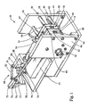
Figure 1 is a perspective view of a gage assembly embodying the principles of the present invention; -
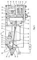
Figure 2 is a top plan view of the gage assembly illustrated inFigure 1 ; -
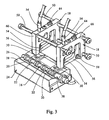
Figure 3 is a partial perspective view of the gage assembly illustrated inFigure 1 and showing a workpiece in an initially received position prior to entering into the gaging areas of the assembly; -
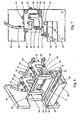
Figure 4 is a perspective view, similar to that ofFigure 3 , illustrating the workpiece having been moved into a gaging position within the gage assembly; -
Figure 5 is a partial side view of the gage assembly illustrated inFigure 4 ; -
Figure 6 is a partial perspective view, similar toFigures 3 and4 , illustrating the workpiece having been completely moved through the gage assembly; -
Figure 7 is a partial side elevational view of the gage assembly illustrated inFigure 6 ; and -
Figure 8 is an enlarged side elevational view of a gage block subassembly similar to those illustrated inFigures 3-7 ; -
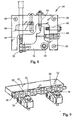
Figure 9 is a perspective view of the part handling slide and support rails, with a workpiece resting thereon, with the remainder of the gage assembly being omitted for clarity. - Referring now to the drawings, seen in
Figures 1 and2 is a gage assembly embodying the principles of the present invention and generally designated at 10. Thegage assembly 10 includes as its primary components apart handling slide 12 and anactuator 14. Theactuator 14 andpart handling slide 12 cooperate with each other to cause movement of aworkpiece 16 through a pair ofgage block subassemblies 18 where readings of the workpiece's diameter in one or more, and preferably at least two, locations is taken. - For simplicity in the figures, the workpiece is at times only illustrated as a cylindrical workpiece. Such a depiction of the
workpiece 16 is seen inFigure 2 . At other times, theworkpiece 16 is depicted as a spool valve having a series of raisedlands 20 and recessed lands 22. In that the dimension of the raised lands 20 is critical to the operation of thespool valve 16, the diameter of the raised lands 20, preferably of least two of the raised lands 20, is the critical dimension measured by thegage assembly 10. Additionally, in certain figures portions of thegage assembly 10 is omitted for clarity. - The
workpiece 16 is provided to thegage assembly 10 by a workpiece delivery means such as an inclined chute allowing theworkpiece 16 to slide, under the influence of gravity, to thegage assembly 10. At thegage assembly 10, theworkpiece 16 is received into a vee-block 24. As per its name, the vee-block 24 has defined therein ashallow recess 26 that is in the shape of a "v". Obviously, therecess 26 may be provided with alternative shapes. Therecess 26 extends the width of the vee-block 24 and may be inclined along its length, from one end of therecess 26 to the other, so as to insure that theworkpiece 16 is fully received onto theupper surface 28 of the vee-block 24. - Also provided in the vee-
block 24 are at least two supports 30. The location of thesupports 30 are preferably chosen so that they support theworkpiece 16 near the ends thereof. Additionally, thesupports 30 define the locations in which, at a minimum, measurements of theworkpiece 16 will be taken. - The supports 30 themselves are in the form of rails received in mounting blocks, and the rails are preferably constructed of a material exhibiting extremely low wear characteristics. One preferred material is carbide. Additionally, the uppermost surface of the
supports 30 are provided such that these surfaces of thesupports 30 are elevated relative theupper surface 28 of the vee-block 24. This is readily seen inFigures 5 and7 . - As previously mentioned, the part handling slide is constructed of a soft tooling, for example polyethylene, and is coupled to the
actuator 14 so as to be moveable in a direction generally transverse to the length or longitudinal axis of therecess 26 formed in the vee-block 24. Thus, the direction of movement of thepart handling slide 12 is in the direction of the longitudinal axis of thesupports 30, which is transverse to the longitudinal axis of theworkpiece 16. Thepart handling slide 12 rests generally above or on theupper surface 28 of the vee-block 24 and is moveable thereacross as a result of the advancement of theconnector rods 32 of theactuator 14. Theactuator 14 may be any variety of actuator heretofore or hereafter devised. As illustrated, theactuator 14 is a pneumatic actuator coupled to apneumatic source 34 via acoupling line 36. In addition to advancing thepart handling slide 12, theactuator 14 similarly causes retraction of thepart handling slide 12 as is conventionally known to be done. - Upon receipt of a
workpiece 16 within the end of therecess 26 of the vee-block 24, the receipt of theworkpiece 16 is detected by aproximity sensor 38 appropriately positioned with respect to the end of therecess 26 in the vee-block 24. Theproximity sensor 38 provides a signal indicating the presence of aworkpiece 16 to acontroller 40, which in turn causes advancement of the actuator and thepart handling slide 12 via thepneumatic source 34. With advancement of thepart handling slide 12, the leadingedge 42 of theslide 12 engages theworkpiece 16 and laterally moves theworkpiece 16 out of therecess 26 of the vee-block 24. This advancement causes theworkpiece 16 to move out of therecess 26 and onto the upper surfaces of thesupports 30 and subsequently it is advanced between thesupports 30 and thegage block subassemblies 18. - The
gage block subassemblies 18 are located opposite of thesupports 30, as mentioned above, and are provided as such through the use of appropriately sized shims andspacers 44. In this manner, the location of thegage block subassemblies 18 matches the geometry or desired locations of measurement of theworkpiece 16. In order to locate thegage block subassemblies 18 and shims andspacers 44, the entire stack ofgage block subassemblies 18, shims andspacers 44 are held betweenend plates 46 extending upward from abase 48 of thegage assembly 10. As readily seen inFigures 2 - 4 , and 6, drawbolts 50 facilitate this holding of component and pass through thegage block subassemblies 18, shims andspacers 44, as well as theend plates 46 themselves. The vee-block 24 and supports 30 may additionally be held in position by theend plate 46. - Each
gage block subassembly 18 includes acontact 52 backed by aprobe 54, such as a common pencil probe. Thecontact 52 is supported on apivot arm 56 through which is provided apivot shaft 58. Thepivot shaft 58 extends through and is common to all of thegage block subassemblies 18, as well as the shims andspacers 44, and is supported in theend plate 46. As best seen inFigure 8 , eachgage block subassembly 18 is provided with anadjustment spring 60. The purpose of theadjustment spring 60 is to set and provide precise adjustment of a contact force exerted by thecontact 52. This contact force is adjusted to a value that stabilizes theworkpiece 16 as it enters and passes through the gage. Such adjustment springs 60 are well known in the industry and therefore further detail regarding its construction is not provided herein. In addition to theadjustment spring 60, thegage block subassemblies 18 may also include stop pins 62, 64, whose positions define the limits of travel of thepivot arm 56 on thepivot shaft 58. - Upon exiting of the
recess 26, the workpiece rides up onto the upper surface of thesupports 30 and enter beneath thegage block subassemblies 18, where the top most portion of the workpiece engages thecontact 52 of eachgage block subassembly 18. In response thereto, thepivot arm 56 is caused to pivot and theprobe 54 detects this movement and produces diameter readings as the workpiece 16 passes between thesupports 30 and thecontacts 52. Software provided in a personal computer or other appropriate device records the peak values at each measured location and determines the desired attributes of theworkpiece 16, including, without limitation, the diameter of theworkpiece 16 at each of the investigated locations. In order to prevent any movement of theprobes 54, theprobes 54 are rigidly supported in a fixed andimmoveable subframe 66 of thegage block subassembly 18. - As seen in
Figures 4 and 5 , theworkpiece 16 has been moved by the part handling slide 12 to a location where theworkpiece 16 is located on thesupports 30 and is immediately beneath thecontacts 52 of thegage block subassemblies 18. Theworkpiece 16 is thereafter moved by thepart handling slide 12 such that it has proceeded from one side (the entry side) of thecontact 52 to the other side (the exit side) of thecontact 52. This latter positioning of theworkpiece 16 is generally illustrated inFigures 6 and 7 . At this point the measurements of theworkpiece 16 have been taken and the workpiece is thereafter provided onto a part handling outfeed conveyor or other means for transporting the workpiece 16 from thegage assembly 10. The part handling conveyor may include a construction allowing forworkpieces 16 not meeting the dimensional tolerances to be rejected to a discarded or scrap parts bin. - While only two
gage block subassemblies 18 are illustrated in the various drawings, it will be readily appreciated that additionalgage block subassemblies 18 can be provided in thegage assembly 10 at locations other than immediately above thesupports 30. In such instances, the additionalgage block subassemblies 18 can generate radial readings that may be used to estimate a diameter or to verify any profiles, such as taper, hourglass or barrel, that may exist along the length of the part. Alternatively, twogage block subassemblies 18 may be provided in an opposed fashion. - In the illustrated figures, while the
workpiece 16 is shown in three locations, namely within therecess 26 of the vee-block 24; immediately between thecontact 52 andsupport 30 and at a point of discharge from thegage assembly 10, it should be understood that the movement of theworkpiece 16 through thegage assembly 10 is of a continuous motion. In other words, the workpiece is always moved through thegage assembly 10 and does not discretely stop at any point in the gage assembly other than its receipt in therecess 26 of the vee-block 24 prior to advancement by thepart handling slide 12. By continuously moving and dynamically gaging theworkpiece 16, faster cycle times forworkpieces 16 can be achieved over prior art gage assemblies, which require static gaging with a discrete and special fixturing of theworkpiece 16. Such prior assemblies first require the specific placing of the workpiece in the gage assembly, then require the measuring of the workpiece by the gage assembly, and finally the removal of the workpiece from the gage assembly by a takeout assembly. Each of the aforementioned steps delays and slows the cycle time for the gauging of a workpiece. In an industry where every workpiece is individually gauged to make sure it meets tolerance requirements, any decrease in cycle time for the gauging process is a major advancement in the production of the parts. - While the
workpiece 16 is preferably dynamically gaged and continuously moved through thegage assembly 10, this should not be interpreted to mean that theworkpiece 16 is has to be continuously moved through thegage assembly 10 or that such movement has to be at a constant rate. While it would decrease cycle times and is not necessary, theworkpiece 16 could momentarily dwell at a specific location while passing through thegage assembly 10. The rate at which theworkpiece 16 is moved through thegage assembly 10 can also be varied so that the rate of movement of theworkpiece 16 decreases when it is in contact, or immediately before contact, with thecontact 52. To facilitate this type of movement, thegage assembly 10 seen inFigures 1 and2 is provided with aretarder mechanism 68 to allow for a varying of the rate at which theworkpiece 16 is continuously moved through thegate assembly 10. - The construction of the
retarder 68 is such that initial movement of thepart handling slide 12, and thus theworkpiece 16, is at an uninhibited rate as provided by theactuator 14. Upon approaching thecontact 52, advancement of thepart handling slide 12 is slowed or retarded. Upon movement of theworkpiece 16 beyond thecontact 52, advancement of the part handling slide andworkpiece 16 is again increased facilitating discharge of the workpiece 16 from thegage assembly 10. - To facilitate the above, a connecting
arm 70 is provided with its distal end attached via apivot 73 to thepart handling slide 12 or the structure coupling the part handling slide 12 to the connectingrods 32 of theactuator 14. Aproximal end 74 of the connectingarm 70 is pivotally supported at 75 on apivot block 76. Thepivot block 76 is in turn rotatably mounted at 77 to aprimary pivot arm 78 which is further rotatably supported at 79 to thebase 48 of thegage assembly 10. Relative rotation of thepivot block 76 relative to theprimary pivot arm 78 is limited by astop 80, provided in thepivot block 76 so as to interferingly engage theprimary pivot arm 78 and thereby limit rotation of thepivot block 76 relative to theprimary pivot arm 78. A biasingmember 82, such as tension spring or similar structure, is provided between thepivot block 76 and thepivot 79,base 48 or other fixed structure. The biasingmember 82 exerts a biasing force on thepivot block 76 andprimary pivot arm 78 such that thestop 80 is urged into contact with theprimary pivot arm 78, thereby urging thepivot block 76 andprimary pivot arm 78 into a biased or initial position. - Upon initial advancement of the
part handling slide 12 by theactuator 14, theconnector arm 70 advances and thepivot block 76 andprimary pivot arm 78 are generally moved in unison, arcuately, but generally in the same direction as thepart handling slide 12. This movement in unison occurs because of the positioning of the pivot 75 (thepivot 75 of theconnector arm 70 and the pivot block 76) inside of the pivot 77 (thepivot 77 of thepivot block 76 and primary pivot arm 78), relative to aline 83 drawn through thepivot 73 and parallel to the direction of movement of thepart handling slide 12. During this initial advancement, theproximal end 74 of the connectingarm 70 pivots at 75 with respect to thepivot block 76. Before theworkpiece 16 engages thecontact 52, theprimary pivot arm 78, via aboss 84, cam follower or other structure thereon, engages theplunger 86 of ashock absorber 88. Theshock absorber 88 is of a common construction and resists depression of theplunger 86 into it. This resistance is provided in an amount that is sufficient to counter act the force of theactuator 14 and thus retard advancement of thepart handling slide 12. The counter force of theshock absorber 88 is not, however, sufficient so as to completely inhibit and stop advancement of theactuator 14 andpart handling slide 12. Rather, movement of thepart handling slide 12, and therefore theworkpiece 16, is merely slowed down. This retarded movement of theworkpiece 16 occurs until theworkpiece 16 has cleared thecontact 52. At this point, theprimary pivot arm 78 has been rotated past perpendicular to the linear direction of movement of thepart handling slide 12. Further advancement of thepart handling slide 12 causes thepivot 75 to be moved to a point where it is located outside of thepivot 77 between thepivot block 76 andprimary pivot arm 78, relative to theline 83 drawn through thepivot 73 and parallel to the direction of movement of thepart handling slide 12. With thepivot 75 in an over center position with respect to thepivot 77 andline 83, thepivot block 76 can rotate relative to theprimary pivot arm 78 allowing theconnector arm 70 to advance unencumbered by theshock absorber 88. It is noted that the biasingmember 82 is sufficiently weak so as to be overcome by the force exerted by theactuator 14. As a result, the rate of movement of thepart handling slide 12 as generated by theactuator 14, and therefore theworkpiece 16, is increased. - With the
workpiece 16 ejected from thegage assembly 10, theactuator 14 retracts thepart handling slide 12 and theretarder 68 resets. Once thepart handling slide 12 has been retracted beyond therecess 26 of the vee-block 24 the next workpiece is delivered into therecess 26 and the process of gauging that workpiece begins with advancement of thepart handling slide 12. - As a person skilled in the art will readily appreciate, the above description is meant as an illustration of implementation of the principles of this invention. This description is not intended to limit the scope or application of this invention. The invention is susceptible to modification, variation and change without departing from the definition given in the following claims.
Claims (18)
- A gage (10) assembly for measuring a generally cylindrical workpiece (16) defining a longitudinal axis, said gage assembly (10) comprising:at least one support member (30) defining a support surface, said support surface being raised relative toa support block (28) within which said support member (30) is mounted;
at least one gage block subassembly (18) generally opposing said support surface and having a moveable contact (52) located in spaced relation from said support surface so as to define a gaging space therebetween, said contact (52) being pivotable in a direction toward said support surface, said gage block assembly (18) also including a measuring device (54) coupled to said contact (52); and
a part handling member (12) coupled to an actuator (14), said actuator (14) adapted to move said part handling member (12) from a position contacting the workpiece (16) on a first side of said gaging space to a position where the workpiece (16) is in said gaging space and to a position where the workpiece (16) is on an opposing side of said gaging space, whereby the workpiece (16) is passed through said gaging space between said support surface and said gage block subassembly (18) in a direction transverse to the longitudinal axis of the workpiece (16). - The gage assembly (10) of claim 1 wherein said part handling member (12) is moved in a direction along a support axis defined by said at least one support member (30), said support axis being transversely oriented relative to the longitudinal axis of the workpiece (16).
- The gage assembly (10) of claim 1 wherein said support member (30) is a rail.
- The gage assembly (10) of claim 3 wherein said rail is of carbide material.
- The gage assembly (10) of claim 3 wherein said rail is generally round in cross-section.
- The gage assembly (10) of claim 1 wherein said part handling member (12) is continuously moveable by said actuator (14) from said first side to said opposing side of said gaging space.
- The gage assembly (10) of claim 1 wherein said part handling member (12) is moveable in a direction transverse to the longitudinal axis of the workpiece (16).
- The gage assembly (10) of claim 1 further comprising a workpiece receiving station located adjacent to said first side of said gaging space, said receiving station including portions defining a workpiece receiving channel oriented transversely to said at least one support member (30).
- The gage assembly (10) of claim 8 wherein said workpiece receiving channel (26) is defined by a V-block (24).
- The gage assembly (10) of claim 1 further comprising a means for moving (70, 73, 74, 75, 76, 77, 78, 80, 82) said part handling member (12) at a variable rate.
- The gage assembly (10) of claim 10 wherein said means for moving (70, 73, 74, 75, 76, 77, 78, 80, 82) said part handling member (12) causes movement of said part handling member (12) at a slower rate when the workpiece (16) is in said gaging space than when the workpiece (16) is on said first side of said gaging space.
- The gage assembly (10) of claim 10, wherein said means for moving (70, 73, 74, 75, 76, 77, 78, 80, 82, 84, 86) said part handling member (12) is a retarder.
- The gage assembly (10) of claim 10 wherein said retarder includes a shock absorber (86, 88).
- The gage assembly (10) of claim 10 wherein said retarder includes a portion (75, 76, 78) rotatable to an over center position.
- A method of measuring a cylindrical workpiece (16) comprising the steps of:providing a generally cylindrical workpiece (16) defining a longitudinal axis therethrough;moving the workpiece (16) from a start position onto at least one support member (30) defining a support surface, said support surface being raised relative to a support block (28) within which said support member (30) is mounted, and into a gaging space defined within a gage assembly;measuring the workpiece at at least two locations along its length when the workpiece is located in the gaging space;moving the workpiece from the gaging space to an exit position where the workpiece is discharged from the gage assembly; andwherein the moving steps continuously move the workpiece from the start position, through the gaging position and to the exit position in a direction transverse to the longitudinal axis of the workpiece.
- The method of claim 15 wherein the moving steps move the workpiece at a variable rate.
- The method of claim 15 wherein the moving steps move the workpiece at a reduced rate at the gaging station than the rate the workpiece is moved from the start position.
- The method of claim 15 wherein the moving steps move the workpiece at a reduced rate at the gaging station than the rate the workpiece is moved to the exit position.
Applications Claiming Priority (2)
| Application Number | Priority Date | Filing Date | Title |
|---|---|---|---|
| US52302703P | 2003-11-18 | 2003-11-18 | |
| PCT/US2004/038759 WO2005049244A2 (en) | 2003-11-18 | 2004-11-18 | Pass-through gage and method of gaging a workpiece |
Publications (3)
| Publication Number | Publication Date |
|---|---|
| EP1684925A2 EP1684925A2 (en) | 2006-08-02 |
| EP1684925A4 EP1684925A4 (en) | 2006-11-22 |
| EP1684925B1 true EP1684925B1 (en) | 2008-03-05 |
Family
ID=34619558
Family Applications (1)
| Application Number | Title | Priority Date | Filing Date |
|---|---|---|---|
| EP04811471A Expired - Lifetime EP1684925B1 (en) | 2003-11-18 | 2004-11-18 | Pass-through gage and method of gaging a workpiece |
Country Status (6)
| Country | Link |
|---|---|
| US (1) | US7526872B2 (en) |
| EP (1) | EP1684925B1 (en) |
| AT (1) | ATE388385T1 (en) |
| DE (1) | DE602004012309T2 (en) |
| ES (1) | ES2300872T3 (en) |
| WO (1) | WO2005049244A2 (en) |
Families Citing this family (1)
| Publication number | Priority date | Publication date | Assignee | Title |
|---|---|---|---|---|
| BR102012028900A2 (en) * | 2012-11-12 | 2014-10-21 | Whirlpool Sa | DIMENSIONAL CONTROL SYSTEM AND METHOD FOR CONNECTED PIPES |
Family Cites Families (13)
| Publication number | Priority date | Publication date | Assignee | Title |
|---|---|---|---|---|
| US2368796A (en) * | 1942-04-22 | 1945-02-06 | Standard Knapp Corp | Bottle removing apparatus |
| SE353958B (en) * | 1967-04-19 | 1973-02-19 | Asea Ab | |
| US3913644A (en) * | 1973-04-21 | 1975-10-21 | Braun Kg Maschf | Debarking machine |
| US4528651A (en) * | 1983-02-04 | 1985-07-09 | Weyerhaeuser Company | Method and apparatus for measurement of length and height of objects |
| NL9100099A (en) * | 1991-01-22 | 1992-08-17 | Aweta Bv | STEEL THICKNESS MEASUREMENT. |
| US5099585A (en) * | 1991-02-19 | 1992-03-31 | Control Gaging, Inc. | In-process machine gage |
| US5643049A (en) * | 1995-07-31 | 1997-07-01 | Control Gaging, Inc. | Floating contact gage for measuring cylindrical workpieces exiting a grinder |
| FR2796143B1 (en) * | 1999-07-07 | 2001-09-21 | Xeda International | DEVICE FOR EVALUATING THE GEOMETRY OF ARTICLES TRANSPORTED BY A CONVEYOR |
| US6645047B1 (en) * | 2000-03-20 | 2003-11-11 | Control Gaging, Inc. | Automatic gage head positioning system |
| US6693274B2 (en) * | 2001-10-29 | 2004-02-17 | Fmc Technologies, Inc. | Method and system of sorting a plurality of received articles having varying size and shape |
| JP4035329B2 (en) * | 2002-01-18 | 2008-01-23 | 本田技研工業株式会社 | Adjustment method of assembly jig |
| US7043851B1 (en) * | 2004-07-30 | 2006-05-16 | Michael Le | Adjustable V-block |
| US7694583B2 (en) * | 2005-05-05 | 2010-04-13 | Control Gaging, Inc. | Gripper gage assembly |
-
2004
- 2004-11-18 US US10/579,816 patent/US7526872B2/en not_active Expired - Fee Related
- 2004-11-18 AT AT04811471T patent/ATE388385T1/en not_active IP Right Cessation
- 2004-11-18 WO PCT/US2004/038759 patent/WO2005049244A2/en not_active Ceased
- 2004-11-18 ES ES04811471T patent/ES2300872T3/en not_active Expired - Lifetime
- 2004-11-18 EP EP04811471A patent/EP1684925B1/en not_active Expired - Lifetime
- 2004-11-18 DE DE602004012309T patent/DE602004012309T2/en not_active Expired - Fee Related
Also Published As
| Publication number | Publication date |
|---|---|
| ATE388385T1 (en) | 2008-03-15 |
| ES2300872T3 (en) | 2008-06-16 |
| WO2005049244A2 (en) | 2005-06-02 |
| US20070089314A1 (en) | 2007-04-26 |
| EP1684925A4 (en) | 2006-11-22 |
| DE602004012309T2 (en) | 2009-03-26 |
| DE602004012309D1 (en) | 2008-04-17 |
| US7526872B2 (en) | 2009-05-05 |
| EP1684925A2 (en) | 2006-08-02 |
| WO2005049244A3 (en) | 2006-01-05 |
Similar Documents
| Publication | Publication Date | Title |
|---|---|---|
| US4884463A (en) | Testing apparatus | |
| US5574233A (en) | Non-contact railway wheel test apparatus and method | |
| EP0315308B1 (en) | Cylindrical coordinate measuring machine | |
| US5823356A (en) | Apparatus and method for insepcting threaded members | |
| EP1715335A1 (en) | Workpiece inspection system | |
| JP2000510583A (en) | Method and apparatus for measuring object thickness at multiple points | |
| JP2008246323A (en) | Inspection equipment for headed work | |
| JP2648647B2 (en) | Press-fit body press-fitting method and press-fit body with press-fit length measuring device | |
| US7526872B2 (en) | Pass-through gage and method of gaging a workpiece | |
| US3938254A (en) | Gaging assembly for automatically controlled wheel lathes | |
| CN218211151U (en) | Roughness quality inspection equipment | |
| CN220602487U (en) | Screw thread rolling machine on-line measuring device | |
| CN117168389A (en) | An online detection device and method for a screw thread rolling machine | |
| JP7143089B2 (en) | Contact type outer diameter measuring device and outer diameter measuring method | |
| CN214039844U (en) | A parallelism inspection device for bed bearing seat | |
| GB2214500A (en) | Tablet alignment apparatus | |
| US4006529A (en) | Check gage for article thickness | |
| US20040159168A1 (en) | Slide adjustment system for brake rotor testing gauges | |
| US2937478A (en) | Process control apparatus | |
| CN211042068U (en) | Quick detection tool of touch cover plate plane degree | |
| CN120194584B (en) | Workpiece size online measurement method and device | |
| CN224175804U (en) | Blank blade flatness detection device | |
| KR19980702621A (en) | Method and apparatus for measuring the suitability of a workpiece for machining | |
| CN112484607A (en) | Parallelism inspection device for lathe bed bearing block | |
| CN113280776B (en) | Diameter measuring device |
Legal Events
| Date | Code | Title | Description |
|---|---|---|---|
| PUAI | Public reference made under article 153(3) epc to a published international application that has entered the european phase |
Free format text: ORIGINAL CODE: 0009012 |
|
| AK | Designated contracting states |
Kind code of ref document: A2 Designated state(s): AT BE BG CH CY CZ DE DK EE ES FI FR GB GR HU IE IS IT LI LU MC NL PL PT RO SE SI SK TR |
|
| AX | Request for extension of the european patent |
Extension state: AL HR LT LV MK YU |
|
| 17P | Request for examination filed |
Effective date: 20060601 |
|
| A4 | Supplementary search report drawn up and despatched |
Effective date: 20061025 |
|
| RIC1 | Information provided on ipc code assigned before grant |
Ipc: G01B 5/10 20060101AFI20061019BHEP |
|
| DAX | Request for extension of the european patent (deleted) | ||
| 17Q | First examination report despatched |
Effective date: 20070219 |
|
| GRAP | Despatch of communication of intention to grant a patent |
Free format text: ORIGINAL CODE: EPIDOSNIGR1 |
|
| GRAS | Grant fee paid |
Free format text: ORIGINAL CODE: EPIDOSNIGR3 |
|
| GRAA | (expected) grant |
Free format text: ORIGINAL CODE: 0009210 |
|
| AK | Designated contracting states |
Kind code of ref document: B1 Designated state(s): AT BE BG CH CY CZ DE DK EE ES FI FR GB GR HU IE IS IT LI LU MC NL PL PT RO SE SI SK TR |
|
| REG | Reference to a national code |
Ref country code: GB Ref legal event code: FG4D |
|
| REG | Reference to a national code |
Ref country code: CH Ref legal event code: EP |
|
| REG | Reference to a national code |
Ref country code: IE Ref legal event code: FG4D |
|
| REF | Corresponds to: |
Ref document number: 602004012309 Country of ref document: DE Date of ref document: 20080417 Kind code of ref document: P |
|
| REG | Reference to a national code |
Ref country code: SE Ref legal event code: TRGR |
|
| REG | Reference to a national code |
Ref country code: ES Ref legal event code: FG2A Ref document number: 2300872 Country of ref document: ES Kind code of ref document: T3 |
|
| PG25 | Lapsed in a contracting state [announced via postgrant information from national office to epo] |
Ref country code: FI Free format text: LAPSE BECAUSE OF FAILURE TO SUBMIT A TRANSLATION OF THE DESCRIPTION OR TO PAY THE FEE WITHIN THE PRESCRIBED TIME-LIMIT Effective date: 20080305 |
|
| PG25 | Lapsed in a contracting state [announced via postgrant information from national office to epo] |
Ref country code: AT Free format text: LAPSE BECAUSE OF FAILURE TO SUBMIT A TRANSLATION OF THE DESCRIPTION OR TO PAY THE FEE WITHIN THE PRESCRIBED TIME-LIMIT Effective date: 20080305 |
|
| NLV1 | Nl: lapsed or annulled due to failure to fulfill the requirements of art. 29p and 29m of the patents act | ||
| PG25 | Lapsed in a contracting state [announced via postgrant information from national office to epo] |
Ref country code: SI Free format text: LAPSE BECAUSE OF FAILURE TO SUBMIT A TRANSLATION OF THE DESCRIPTION OR TO PAY THE FEE WITHIN THE PRESCRIBED TIME-LIMIT Effective date: 20080305 Ref country code: PL Free format text: LAPSE BECAUSE OF FAILURE TO SUBMIT A TRANSLATION OF THE DESCRIPTION OR TO PAY THE FEE WITHIN THE PRESCRIBED TIME-LIMIT Effective date: 20080305 Ref country code: BE Free format text: LAPSE BECAUSE OF FAILURE TO SUBMIT A TRANSLATION OF THE DESCRIPTION OR TO PAY THE FEE WITHIN THE PRESCRIBED TIME-LIMIT Effective date: 20080305 |
|
| PG25 | Lapsed in a contracting state [announced via postgrant information from national office to epo] |
Ref country code: SK Free format text: LAPSE BECAUSE OF FAILURE TO SUBMIT A TRANSLATION OF THE DESCRIPTION OR TO PAY THE FEE WITHIN THE PRESCRIBED TIME-LIMIT Effective date: 20080305 Ref country code: CZ Free format text: LAPSE BECAUSE OF FAILURE TO SUBMIT A TRANSLATION OF THE DESCRIPTION OR TO PAY THE FEE WITHIN THE PRESCRIBED TIME-LIMIT Effective date: 20080305 Ref country code: NL Free format text: LAPSE BECAUSE OF FAILURE TO SUBMIT A TRANSLATION OF THE DESCRIPTION OR TO PAY THE FEE WITHIN THE PRESCRIBED TIME-LIMIT Effective date: 20080305 Ref country code: PT Free format text: LAPSE BECAUSE OF FAILURE TO SUBMIT A TRANSLATION OF THE DESCRIPTION OR TO PAY THE FEE WITHIN THE PRESCRIBED TIME-LIMIT Effective date: 20080805 |
|
| PG25 | Lapsed in a contracting state [announced via postgrant information from national office to epo] |
Ref country code: RO Free format text: LAPSE BECAUSE OF FAILURE TO SUBMIT A TRANSLATION OF THE DESCRIPTION OR TO PAY THE FEE WITHIN THE PRESCRIBED TIME-LIMIT Effective date: 20080305 |
|
| EN | Fr: translation not filed | ||
| PG25 | Lapsed in a contracting state [announced via postgrant information from national office to epo] |
Ref country code: IS Free format text: LAPSE BECAUSE OF FAILURE TO SUBMIT A TRANSLATION OF THE DESCRIPTION OR TO PAY THE FEE WITHIN THE PRESCRIBED TIME-LIMIT Effective date: 20080705 |
|
| PLBE | No opposition filed within time limit |
Free format text: ORIGINAL CODE: 0009261 |
|
| STAA | Information on the status of an ep patent application or granted ep patent |
Free format text: STATUS: NO OPPOSITION FILED WITHIN TIME LIMIT |
|
| PG25 | Lapsed in a contracting state [announced via postgrant information from national office to epo] |
Ref country code: DK Free format text: LAPSE BECAUSE OF FAILURE TO SUBMIT A TRANSLATION OF THE DESCRIPTION OR TO PAY THE FEE WITHIN THE PRESCRIBED TIME-LIMIT Effective date: 20080305 |
|
| PGFP | Annual fee paid to national office [announced via postgrant information from national office to epo] |
Ref country code: DE Payment date: 20081210 Year of fee payment: 5 |
|
| 26N | No opposition filed |
Effective date: 20081208 |
|
| PGFP | Annual fee paid to national office [announced via postgrant information from national office to epo] |
Ref country code: ES Payment date: 20081113 Year of fee payment: 5 |
|
| PGFP | Annual fee paid to national office [announced via postgrant information from national office to epo] |
Ref country code: IT Payment date: 20081120 Year of fee payment: 5 |
|
| PG25 | Lapsed in a contracting state [announced via postgrant information from national office to epo] |
Ref country code: BG Free format text: LAPSE BECAUSE OF FAILURE TO SUBMIT A TRANSLATION OF THE DESCRIPTION OR TO PAY THE FEE WITHIN THE PRESCRIBED TIME-LIMIT Effective date: 20080605 Ref country code: EE Free format text: LAPSE BECAUSE OF FAILURE TO SUBMIT A TRANSLATION OF THE DESCRIPTION OR TO PAY THE FEE WITHIN THE PRESCRIBED TIME-LIMIT Effective date: 20080305 Ref country code: FR Free format text: LAPSE BECAUSE OF FAILURE TO SUBMIT A TRANSLATION OF THE DESCRIPTION OR TO PAY THE FEE WITHIN THE PRESCRIBED TIME-LIMIT Effective date: 20081226 |
|
| PG25 | Lapsed in a contracting state [announced via postgrant information from national office to epo] |
Ref country code: MC Free format text: LAPSE BECAUSE OF NON-PAYMENT OF DUE FEES Effective date: 20081130 |
|
| REG | Reference to a national code |
Ref country code: CH Ref legal event code: PL |
|
| GBPC | Gb: european patent ceased through non-payment of renewal fee |
Effective date: 20081118 |
|
| PG25 | Lapsed in a contracting state [announced via postgrant information from national office to epo] |
Ref country code: CY Free format text: LAPSE BECAUSE OF FAILURE TO SUBMIT A TRANSLATION OF THE DESCRIPTION OR TO PAY THE FEE WITHIN THE PRESCRIBED TIME-LIMIT Effective date: 20080305 |
|
| PG25 | Lapsed in a contracting state [announced via postgrant information from national office to epo] |
Ref country code: IE Free format text: LAPSE BECAUSE OF NON-PAYMENT OF DUE FEES Effective date: 20081118 Ref country code: LI Free format text: LAPSE BECAUSE OF NON-PAYMENT OF DUE FEES Effective date: 20081130 Ref country code: CH Free format text: LAPSE BECAUSE OF NON-PAYMENT OF DUE FEES Effective date: 20081130 |
|
| PG25 | Lapsed in a contracting state [announced via postgrant information from national office to epo] |
Ref country code: GB Free format text: LAPSE BECAUSE OF NON-PAYMENT OF DUE FEES Effective date: 20081118 |
|
| PG25 | Lapsed in a contracting state [announced via postgrant information from national office to epo] |
Ref country code: LU Free format text: LAPSE BECAUSE OF NON-PAYMENT OF DUE FEES Effective date: 20081118 Ref country code: HU Free format text: LAPSE BECAUSE OF FAILURE TO SUBMIT A TRANSLATION OF THE DESCRIPTION OR TO PAY THE FEE WITHIN THE PRESCRIBED TIME-LIMIT Effective date: 20080906 |
|
| PG25 | Lapsed in a contracting state [announced via postgrant information from national office to epo] |
Ref country code: TR Free format text: LAPSE BECAUSE OF FAILURE TO SUBMIT A TRANSLATION OF THE DESCRIPTION OR TO PAY THE FEE WITHIN THE PRESCRIBED TIME-LIMIT Effective date: 20080305 |
|
| PG25 | Lapsed in a contracting state [announced via postgrant information from national office to epo] |
Ref country code: GR Free format text: LAPSE BECAUSE OF FAILURE TO SUBMIT A TRANSLATION OF THE DESCRIPTION OR TO PAY THE FEE WITHIN THE PRESCRIBED TIME-LIMIT Effective date: 20080606 |
|
| PG25 | Lapsed in a contracting state [announced via postgrant information from national office to epo] |
Ref country code: DE Free format text: LAPSE BECAUSE OF NON-PAYMENT OF DUE FEES Effective date: 20100601 |
|
| REG | Reference to a national code |
Ref country code: ES Ref legal event code: FD2A Effective date: 20110310 |
|
| PG25 | Lapsed in a contracting state [announced via postgrant information from national office to epo] |
Ref country code: IT Free format text: LAPSE BECAUSE OF NON-PAYMENT OF DUE FEES Effective date: 20091118 |
|
| PG25 | Lapsed in a contracting state [announced via postgrant information from national office to epo] |
Ref country code: ES Free format text: LAPSE BECAUSE OF NON-PAYMENT OF DUE FEES Effective date: 20110309 |
|
| PG25 | Lapsed in a contracting state [announced via postgrant information from national office to epo] |
Ref country code: ES Free format text: LAPSE BECAUSE OF NON-PAYMENT OF DUE FEES Effective date: 20091119 |
|
| PGFP | Annual fee paid to national office [announced via postgrant information from national office to epo] |
Ref country code: SE Payment date: 20221125 Year of fee payment: 19 |
|
| REG | Reference to a national code |
Ref country code: SE Ref legal event code: EUG |
|
| PG25 | Lapsed in a contracting state [announced via postgrant information from national office to epo] |
Ref country code: SE Free format text: LAPSE BECAUSE OF NON-PAYMENT OF DUE FEES Effective date: 20231119 |