EP1684615B1 - Mattress protection - Google Patents
Mattress protection Download PDFInfo
- Publication number
- EP1684615B1 EP1684615B1 EP04798649A EP04798649A EP1684615B1 EP 1684615 B1 EP1684615 B1 EP 1684615B1 EP 04798649 A EP04798649 A EP 04798649A EP 04798649 A EP04798649 A EP 04798649A EP 1684615 B1 EP1684615 B1 EP 1684615B1
- Authority
- EP
- European Patent Office
- Prior art keywords
- mattress
- cover
- protector
- layer
- mattress protector
- Prior art date
- Legal status (The legal status is an assumption and is not a legal conclusion. Google has not performed a legal analysis and makes no representation as to the accuracy of the status listed.)
- Expired - Lifetime
Links
- 230000001012 protector Effects 0.000 claims abstract description 42
- 210000001124 body fluid Anatomy 0.000 claims abstract description 25
- 239000010839 body fluid Substances 0.000 claims abstract description 24
- 230000002745 absorbent Effects 0.000 claims abstract description 8
- 239000002250 absorbent Substances 0.000 claims abstract description 8
- 230000000007 visual effect Effects 0.000 claims abstract description 3
- XLYOFNOQVPJJNP-UHFFFAOYSA-N water Substances O XLYOFNOQVPJJNP-UHFFFAOYSA-N 0.000 claims description 30
- 239000010410 layer Substances 0.000 claims description 28
- 239000012530 fluid Substances 0.000 claims description 24
- 230000008859 change Effects 0.000 claims description 20
- 239000004744 fabric Substances 0.000 claims description 18
- 210000002700 urine Anatomy 0.000 claims description 13
- 239000000463 material Substances 0.000 claims description 8
- 239000011229 interlayer Substances 0.000 claims description 7
- 239000004020 conductor Substances 0.000 claims description 5
- 239000002759 woven fabric Substances 0.000 claims description 5
- 230000000694 effects Effects 0.000 claims description 4
- 230000002427 irreversible effect Effects 0.000 claims description 4
- 230000001939 inductive effect Effects 0.000 claims description 3
- 239000011159 matrix material Substances 0.000 claims description 3
- 238000000926 separation method Methods 0.000 claims description 3
- 230000009471 action Effects 0.000 claims description 2
- 238000010438 heat treatment Methods 0.000 claims description 2
- 150000002894 organic compounds Chemical class 0.000 claims description 2
- 239000011241 protective layer Substances 0.000 claims description 2
- 229910001285 shape-memory alloy Inorganic materials 0.000 claims description 2
- 230000037303 wrinkles Effects 0.000 claims description 2
- 238000012544 monitoring process Methods 0.000 abstract description 3
- 239000000126 substance Substances 0.000 abstract description 2
- 230000001684 chronic effect Effects 0.000 abstract 1
- 230000001681 protective effect Effects 0.000 abstract 1
- FAPWRFPIFSIZLT-UHFFFAOYSA-M Sodium chloride Chemical compound [Na+].[Cl-] FAPWRFPIFSIZLT-UHFFFAOYSA-M 0.000 description 29
- 238000012360 testing method Methods 0.000 description 28
- 239000012153 distilled water Substances 0.000 description 20
- 238000009736 wetting Methods 0.000 description 16
- 230000004044 response Effects 0.000 description 9
- 239000011780 sodium chloride Substances 0.000 description 8
- 238000000034 method Methods 0.000 description 5
- 230000006399 behavior Effects 0.000 description 4
- 238000007726 management method Methods 0.000 description 4
- 238000010586 diagram Methods 0.000 description 3
- 238000005516 engineering process Methods 0.000 description 3
- 230000001965 increasing effect Effects 0.000 description 3
- 230000000474 nursing effect Effects 0.000 description 3
- 230000035945 sensitivity Effects 0.000 description 3
- 239000004677 Nylon Substances 0.000 description 2
- WCUXLLCKKVVCTQ-UHFFFAOYSA-M Potassium chloride Chemical compound [Cl-].[K+] WCUXLLCKKVVCTQ-UHFFFAOYSA-M 0.000 description 2
- BQCADISMDOOEFD-UHFFFAOYSA-N Silver Chemical compound [Ag] BQCADISMDOOEFD-UHFFFAOYSA-N 0.000 description 2
- XSQUKJJJFZCRTK-UHFFFAOYSA-N Urea Chemical compound NC(N)=O XSQUKJJJFZCRTK-UHFFFAOYSA-N 0.000 description 2
- 238000012550 audit Methods 0.000 description 2
- 239000004202 carbamide Substances 0.000 description 2
- 239000003792 electrolyte Substances 0.000 description 2
- 208000015181 infectious disease Diseases 0.000 description 2
- 230000005055 memory storage Effects 0.000 description 2
- 229920001778 nylon Polymers 0.000 description 2
- 235000014594 pastries Nutrition 0.000 description 2
- 230000008569 process Effects 0.000 description 2
- 229910052709 silver Inorganic materials 0.000 description 2
- 239000004332 silver Substances 0.000 description 2
- 238000005406 washing Methods 0.000 description 2
- 241000894006 Bacteria Species 0.000 description 1
- 206010017076 Fracture Diseases 0.000 description 1
- WQZGKKKJIJFFOK-GASJEMHNSA-N Glucose Natural products OC[C@H]1OC(O)[C@H](O)[C@@H](O)[C@@H]1O WQZGKKKJIJFFOK-GASJEMHNSA-N 0.000 description 1
- 208000004210 Pressure Ulcer Diseases 0.000 description 1
- 229910000831 Steel Inorganic materials 0.000 description 1
- 150000001413 amino acids Chemical class 0.000 description 1
- 238000004458 analytical method Methods 0.000 description 1
- WQZGKKKJIJFFOK-VFUOTHLCSA-N beta-D-glucose Chemical compound OC[C@H]1O[C@@H](O)[C@H](O)[C@@H](O)[C@@H]1O WQZGKKKJIJFFOK-VFUOTHLCSA-N 0.000 description 1
- 230000005540 biological transmission Effects 0.000 description 1
- 230000036760 body temperature Effects 0.000 description 1
- 239000002131 composite material Substances 0.000 description 1
- 238000009833 condensation Methods 0.000 description 1
- 230000005494 condensation Effects 0.000 description 1
- 230000007547 defect Effects 0.000 description 1
- 230000006866 deterioration Effects 0.000 description 1
- 238000001035 drying Methods 0.000 description 1
- 239000006260 foam Substances 0.000 description 1
- 238000009472 formulation Methods 0.000 description 1
- 230000002538 fungal effect Effects 0.000 description 1
- 239000008103 glucose Substances 0.000 description 1
- 230000036541 health Effects 0.000 description 1
- 238000011534 incubation Methods 0.000 description 1
- 239000012678 infectious agent Substances 0.000 description 1
- 238000007689 inspection Methods 0.000 description 1
- 150000002500 ions Chemical class 0.000 description 1
- 239000007788 liquid Substances 0.000 description 1
- 239000004973 liquid crystal related substance Substances 0.000 description 1
- 229910052751 metal Inorganic materials 0.000 description 1
- 239000002184 metal Substances 0.000 description 1
- 230000027939 micturition Effects 0.000 description 1
- 239000000203 mixture Substances 0.000 description 1
- 244000052769 pathogen Species 0.000 description 1
- 230000035515 penetration Effects 0.000 description 1
- 239000001103 potassium chloride Substances 0.000 description 1
- 235000011164 potassium chloride Nutrition 0.000 description 1
- 238000002360 preparation method Methods 0.000 description 1
- 238000005096 rolling process Methods 0.000 description 1
- 239000001488 sodium phosphate Substances 0.000 description 1
- 229910000162 sodium phosphate Inorganic materials 0.000 description 1
- 238000000638 solvent extraction Methods 0.000 description 1
- 230000007480 spreading Effects 0.000 description 1
- 238000003892 spreading Methods 0.000 description 1
- 239000010959 steel Substances 0.000 description 1
- 238000001356 surgical procedure Methods 0.000 description 1
- 230000009182 swimming Effects 0.000 description 1
- 230000001960 triggered effect Effects 0.000 description 1
- RYFMWSXOAZQYPI-UHFFFAOYSA-K trisodium phosphate Chemical compound [Na+].[Na+].[Na+].[O-]P([O-])([O-])=O RYFMWSXOAZQYPI-UHFFFAOYSA-K 0.000 description 1
Images




Classifications
-
- A—HUMAN NECESSITIES
- A61—MEDICAL OR VETERINARY SCIENCE; HYGIENE
- A61F—FILTERS IMPLANTABLE INTO BLOOD VESSELS; PROSTHESES; DEVICES PROVIDING PATENCY TO, OR PREVENTING COLLAPSING OF, TUBULAR STRUCTURES OF THE BODY, e.g. STENTS; ORTHOPAEDIC, NURSING OR CONTRACEPTIVE DEVICES; FOMENTATION; TREATMENT OR PROTECTION OF EYES OR EARS; BANDAGES, DRESSINGS OR ABSORBENT PADS; FIRST-AID KITS
- A61F5/00—Orthopaedic methods or devices for non-surgical treatment of bones or joints; Nursing devices ; Anti-rape devices
- A61F5/48—Devices for preventing wetting or pollution of the bed
-
- A—HUMAN NECESSITIES
- A47—FURNITURE; DOMESTIC ARTICLES OR APPLIANCES; COFFEE MILLS; SPICE MILLS; SUCTION CLEANERS IN GENERAL
- A47C—CHAIRS; SOFAS; BEDS
- A47C27/00—Spring, stuffed or fluid mattresses or cushions specially adapted for chairs, beds or sofas
- A47C27/002—Mattress or cushion tickings or covers
- A47C27/005—Mattress or cushion tickings or covers liquid-impermeable
- A47C27/006—Mattress or cushion tickings or covers liquid-impermeable breathable
Definitions
- the present invention concerns improvements in and relating to mattress protectors and provides methods and means for monitoring the integrity of a mattress protector to determine if bodily fluids have penetrated through to the mattress.
- mattress covers be impenetrable to body fluids so that the inner core, which usually comprises a composite of foams, does not become contaminated. Once the integrity of the cover has been breached (technically known as "strike-through"), the potential for the mattress core to become a medium for the growth of bacteria and fungal spores is high. The combined presence of moisture, infectious agents and the warmth continuously generated by the multiple users of the mattress is an ideal incubation environment for pathogens.
- This invention seeks as one objective to provide a new technology to enable mattress audit technicians or hospital staff to determine whether a mattress cover has leaked at any time in the mattress' service, without removing the cover. Avoiding the necessity of removing the mattress cover both simplifies the task and reduces the risk of infections spreading.
- a mattress protector to shield a mattress or mattress core from body fluids
- the protector comprising a shielding cover for fitting over the mattress or mattress core, the shielding cover having a layer that is impermeable to body fluids that is outermost in use, and a detector within the cover or below or in an under layer of the cover, the detector being below the impermeable layer of the shielding cover, to detect body fluid that has passed into or through the cover, the fluid having penetrated the impermeable layer of the shielding cover.
- the protector may be separate from or integral with a mattress and, in the latter case, may comprise all or part of the casing that envelopes the mattress core.
- the substantially liquid-impermeable cover is preferably breathable.
- the cover is a transparent cover for a mattress with an inter-layer or under-layer, suitably an absorbent under-layer, having a dye that is activated by a body fluid to provide a visual indication of presence of the body fluid.
- the inter- or under-layer is preferably impregnated with the dye.
- the dye is preferably unaffected by water vapour.
- body fluid such as urine penetrates through the mattress
- indicators in the dye will show through the transparent cover.
- An indicator specific to urine and unaffected by water is advantageous, since water vapour may be present in the mattress during correct functioning of the cover, where the cover is specified to be "breathable", i.e. transmits water vapour.
- the absorbent layer is made from a stretchable material, suitably crepe or similar, in order to minimise perturbation of the cover stretch properties.
- incisions could be made in the absorbent sheet, similar to those in lattice pastry or expanded sheet metal, so as to allow stretch in the sheet material.
- the detector comprises an apparatus that monitors electrical conductivity.
- This suitably uses electrically conductive threads or fibres such as, for example, an electrically conductive yarn (eg, silver plated nylon), forming rows or a matrix over the inter- or under-layer.
- electrically conductive yarn eg, silver plated nylon
- the threads form the warp or weft of a thin flexible woven under- layer.
- the mattress in this second embodiment is fitted with a small processor, preferably a micro-processor, which monitors the electrical conductivity between neighbouring conductive threads in the sensing layer and records any change.
- a small processor preferably a micro-processor, which monitors the electrical conductivity between neighbouring conductive threads in the sensing layer and records any change.
- the micro-processor may have a very low power consumption and could be battery-powered and be interrogated using an inductive link by an external device to determine if any leak events had occurred.
- a transparent cover 3 is provided for the mattress 1, with an absorbent under-layer 2 impregnated with a dye that is activated by a body fluid such as urine but not by water vapour. If urine penetrates through the mattress indicators in the dye show through the transparent cover.
- An indicator specific to urine, or rather specific for organic compounds such as urea or glucose present in urine, is advantageous, since water vapour may be present in the mattress during correct functioning of the cover.
- Many mattress covers are specified to be "breathable", i.e. they transmit water vapour. Alternatively, a moisture-sensitive dye sensitive to a threshold level of moisture greater than that prevalent as water vapour may be used.
- the absorbent layer is here stretchable, suitably being made from a stretchable fabric, eg a crepe-style material, or is incised/ partitioned, in order to minimise perturbation of the cover stretch properties.
- threads of electrically conductive silver plated nylon yarn are used forming the warp or weft of a thin flexible woven under layer 6 of the mattress protector beneath the substantially liquid impermeable shielding layer 5 of the cover.
- the mattress 4 is fitted with a small microprocessor 7, which monitors the electrical conductivity between neighbouring conductive threads 12, 13 in the sensing layer 6. In the event of a leak of ionic (electrically conductive) fluid, a short circuit between threads is detected via the threads 12,13 and recorded by the microprocessor 7.
- the microprocessor 7 has a very low power consumption and is thus battery powered and entirely self-contained. It can be interrogated using an inductive link by an external device to determine if any leak events had occurred.
- a battery 8 supplies power to the microprocessor 7 as well as supplying positive and negative threads 12 and 13 respectively.
- the presence of an electrolyte such as urine 10 causes a short circuit between the two threads 12 and 13, so changing the high/low state monitored at digital input 11 to the microprocessor 7. This event is stored in the memory of the microprocessor 7.
- the assembly is interrogated by means of a radio wand, the signal of which is picked up by antenna 14. This causes the microprocessor 7 to respond with an appropriate signal to indicate whether a short has occurred at any time in the past.
- This remote interrogation of the microprocessor 7 can take place using conventional RFID technology, without the necessity of removing the mattress cover 5 (so causing a spread of infection), or even the bedclothes.
- the circuit is completed by the presence of a leak that joins any two or more adjacent lines (weft bars of conductive yarn).
- the tracks of conductive yarn can be produced in various geometries to provide suitable adjacent positive and negative tracks at appropriate spacings over the mattress surface. An example of this system is illustrated in principle in figure 4 .
- the specimens were assessed for their response to distilled water and to a 4% saline solution.
- the former should indicate the likely behaviour if condensation builds up in the system during use, with an alarm not desirable in this circumstance.
- the latter should indicate the likely behaviour when urine becomes present in the system as a result of the mattress cover leaking, with an alarm to be triggered.
- the sensitivity of the system to distilled water will be much lower than the sensitivity to saline.
- the specimen to be tested was placed on a non-absorbent bench, in an unconditioned lab. The ambient temperature was approximately 19°C for all tests.
- the terminals at the end of each side of the specimen were connected to a Center SE122 True RMS multimeter, set to measure the resistance of the specimen. This was connected to the serial port of a laptop computer running the SE120 Testlink data collection software. The resistance of the specimen was acquired every two seconds during the test. This data was saved in CSV form (comma separated values) which was then exported to Microsoft Excel for further analysis.
- the fluid was not placed onto the specimen in one dose. Three one-drop doses were applied one minute apart. This was intended to simulate the more gradual fluid penetration that is likely to occur with a mattress cover leak.
- the fluid was placed directly onto a conductive stripe in the fabric. This placement should represent the slowest response that the specimen could provide, as the fluid has to traverse an entire non-conductive stripe to reach an adjacent conductive stripe and trigger a change in resistance. The fastest response could be expected if the drops were placed exactly between the conductive stripes, as only half a non-conductive stripe would need to be traversed to trigger the response in this case.
- the distilled water leaves no residue on the fabric, so any washing or rinsing after each of these tests is redundant.
- the second saline test is, therefore, carried out on a fabric that has a sodium chloride residue on it, but before carrying out this test it was confirmed that the resistance had increased to a high level.
- the sodium chloride is non-conductive, as there is no means for ion movement (and hence conduction). If the second test involved placing the drops onto the exact same region as the previous then the effect may be equivalent to having doubled the saline solution concentration. However, each of the four tests was carried out on a different region of the specimen, with no overlap of the (previously) wetted areas.
- MLSF001 For MLSF001 the change in resistance is by a factor of 53 and 7 for each of the tests, for MLSF002 it is by a factor of 32 and 26 for each of the tests, and for MLSF003 it is by a factor of 340 and 530.
- the magnitude of the resistance drop is much greater for the saline solution, especially for the first of the two tests on each specimen.
- the lowered starting resistance means that although the final resistance is close to that of the first test, the factor by which it has reduced is lower.
- the response time appears to be proportional to conductive stripe spacing, with MLSF003 faster than MLSF002, which was faster than MLSF001. Only MLSF002 responded noticeably faster with saline solution than with distilled water.
- the change in resistance is by a factor of 1200 and 190 for each of the tests, for MLSF002 it is by a factor of 460 and 390 for each of the tests, and for MLSF003 it is by a factor of 6900 and 48.
- positive and negative tracks are provided on opposite sides of the fabric.
- electrical continuity between positive and negative tracks is provided as before, when wetting occurs.
- false positives do not occur as a result of wrinkles or folds in the fabric bringing positive and negative tracks together, as may possibly occur when positive and negative tracks occur on the same side of the fabric.
- a protective layer of fabric can be applied to cover the electrical tracks, to provide mechanical separation between tracks in the event of creasing or folding.
- This covering layer may be pervious to fluids, and so still allow electrical continuity between tracks by means of wetting.
- the conductive yarns are included in the system as a knitted fabric, rather than a woven fabric. This provides for stretchability of the material, which may be advantageous by causing less perturbation to the pressure-distributive properties of the mattress.
- rows of staggered slits may be provided in the woven fabric so as to allow expansion of the material in a similar fashion to lattice pastry or expanded steel mesh. These slits may occur between tracks so as not to interfere with the electrical circuit. The slits would allow expansion and stretchability in the fabric, so causing less perturbation to the pressure-distributive properties.
- soiling of the mattress core is immediately transmitted (by means of a radio frequency transmitter situated inside the mattress) to a remote receiver connected to a computer.
- a radio frequency transmitter situated inside the mattress
- This may be for example the nurses station, which records the time and location of the adverse event, so that suitable action may be taken.
- local interrogation of the mattress is not required, nor is local memory storage within the mattress.
- soiling of the mattress identified by the circuit prompts the microcontroller to effect an irreversible change in a visible indicator.
- the indicator may take the form of a permanently-changed bistable liquid crystal display, visible from the outside of the mattress cover with an appropriate clear window.
- the visible indicator may comprise a combination of a small heating element inside the mattress cover, and an irreversible thermochromic strip in the corresponding place outside the mattress cover. Choosing an appropriate temperature threshold well above body temperature would eliminate false positives due to skin contact.
- the position of a mechanical flag can be activated irreversibly by means of a solenoid or other mechanical actuator. The position/condition of this flag may be determined by feeling through the mattress cover, without opening the cover. This flag may consist of a shaped memory alloy, which regains a predetermined shape irreversibly when subjected to an electrical stimulus.
- any of these embodiments obviate the need for electronic memory storage within the mattress, or for radio transmission, while still allowing inspection without opening the mattress cover, to determine whether historical leaks have occurred.
Landscapes
- Health & Medical Sciences (AREA)
- Engineering & Computer Science (AREA)
- General Health & Medical Sciences (AREA)
- Public Health (AREA)
- Orthopedic Medicine & Surgery (AREA)
- Biomedical Technology (AREA)
- Heart & Thoracic Surgery (AREA)
- Vascular Medicine (AREA)
- Life Sciences & Earth Sciences (AREA)
- Animal Behavior & Ethology (AREA)
- Environmental & Geological Engineering (AREA)
- Nursing (AREA)
- Veterinary Medicine (AREA)
- Orthopedics, Nursing, And Contraception (AREA)
- Mattresses And Other Support Structures For Chairs And Beds (AREA)
- Thermotherapy And Cooling Therapy Devices (AREA)
- Measuring And Recording Apparatus For Diagnosis (AREA)
- Invalid Beds And Related Equipment (AREA)
- Bedding Items (AREA)
- Woven Fabrics (AREA)
Abstract
Description
- The present invention concerns improvements in and relating to mattress protectors and provides methods and means for monitoring the integrity of a mattress protector to determine if bodily fluids have penetrated through to the mattress.
- Hospital mattresses form the platform for delivering routine care to patients. In recent years increasing attention has been paid to their specifications, including their ability to improve comfort for patients, prevent pressure ulcers, appropriately stabilise patients with fractures or following surgery, reduce the risk of rolling off the mattress, and facilitate nursing management of the patients including toileting. A further requirement is that mattress covers be impenetrable to body fluids so that the inner core, which usually comprises a composite of foams, does not become contaminated. Once the integrity of the cover has been breached (technically known as "strike-through"), the potential for the mattress core to become a medium for the growth of bacteria and fungal spores is high. The combined presence of moisture, infectious agents and the warmth continuously generated by the multiple users of the mattress is an ideal incubation environment for pathogens.
- In September 1999 the Medical Devices Agency issued a Safety Notice (MDA SN1999 (31) alerting hospitals of the hazards to staff and patients associated with mattresses in poor condition. In recent years procedures for supplying and servicing mattresses in hospitals have changed. Traditionally nursing staff have ordered, cleaned and audited the condition of mattresses, but with increasing pressure on their time, non-patient contact activities such as mattress management are being increasingly devolved to non-nursing staff. The UK is leading Europe in the implementation of "total mattress management" and "total bed management" contracts where the manufacturer/distributors of hospital mattress are contracted to supply mattresses against clinical and technical specifications. These specifications are led by the NHS Purchasing and Supply Agency (PASA).
- Under these arrangements contractors undertake the responsibility of not only supplying hospital mattresses but also auditing their condition, ensuring that worn or leaking mattresses are withdrawn and replaced. At present this entails technicians undertaking a "sweep" through the hospital inspecting mattresses individually, physically checking for deterioration of the mechanical support characteristics of the mattress core, and inspecting for evidence of "strike-through". This is a very unpleasant process and may also represent a potential health and safety risk to staff undertaking the audits.
- Technology exists for monitoring soiling of sheets such as draw sheets that cover mattresses as exemplified in
US-6,341,393 (Votel ). - This invention seeks as one objective to provide a new technology to enable mattress audit technicians or hospital staff to determine whether a mattress cover has leaked at any time in the mattress' service, without removing the cover. Avoiding the necessity of removing the mattress cover both simplifies the task and reduces the risk of infections spreading.
- According to a first aspect of the present invention there is provided a mattress protector to shield a mattress or mattress core from body fluids, the protector comprising a shielding cover for fitting over the mattress or mattress core, the shielding cover having a layer that is impermeable to body fluids that is outermost in use, and a detector within the cover or below or in an under layer of the cover, the detector being below the impermeable layer of the shielding cover, to detect body fluid that has passed into or through the cover, the fluid having penetrated the impermeable layer of the shielding cover. The protector may be separate from or integral with a mattress and, in the latter case, may comprise all or part of the casing that envelopes the mattress core. The substantially liquid-impermeable cover is preferably breathable.
- In a first preferred embodiment of the invention the cover is a transparent cover for a mattress with an inter-layer or under-layer, suitably an absorbent under-layer, having a dye that is activated by a body fluid to provide a visual indication of presence of the body fluid. The inter- or under-layer is preferably impregnated with the dye.
- The dye is preferably unaffected by water vapour. However, if body fluid such as urine penetrates through the mattress, indicators in the dye will show through the transparent cover. An indicator specific to urine and unaffected by water (many of which are commercially available and are used, for example, to expose urination in swimming pools) is advantageous, since water vapour may be present in the mattress during correct functioning of the cover, where the cover is specified to be "breathable", i.e. transmits water vapour.
- Preferably, the absorbent layer is made from a stretchable material, suitably crepe or similar, in order to minimise perturbation of the cover stretch properties. Alternatively, incisions could be made in the absorbent sheet, similar to those in lattice pastry or expanded sheet metal, so as to allow stretch in the sheet material.
- In a second preferred embodiment of the invention, instead of having a dye-based detector the detector comprises an apparatus that monitors electrical conductivity. This suitably uses electrically conductive threads or fibres such as, for example, an electrically conductive yarn (eg, silver plated nylon), forming rows or a matrix over the inter- or under-layer. Suitably the threads form the warp or weft of a thin flexible woven under- layer.
- Preferably the mattress in this second embodiment is fitted with a small processor, preferably a micro-processor, which monitors the electrical conductivity between neighbouring conductive threads in the sensing layer and records any change.
- In the event of a leak of ionic (electrically conductive) fluid, as all body fluids are, a short circuit between threads will be detected and recorded. The micro-processor may have a very low power consumption and could be battery-powered and be interrogated using an inductive link by an external device to determine if any leak events had occurred.
- The preferred embodiments of the present invention will now be more particularly described by way of example with reference to the accompanying drawings, wherein:
-
Figure 1 is a sectional view of an end of a mattress encased in the mattress protector of the first preferred embodiment; -
Figure 2 is an isometric view of a mattress encased in a mattress protector of the second preferred embodiment, showing the outer cover part cut-away to view the matrix of electrically conductive yarn that underlies the outer cover; -
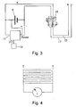
Figure 3 is a schematic circuit diagram for the electrical conductivity-based detector of the second preferred embodiment; -
Figure 4 is a further schematic circuit diagram for the electrical conductivity-based detector of the second preferred embodiment showing an example suitable geometry of the positive and negative tracks of the detector; -
Figure 5 is a photographic image of a first example of electrical conductivity-based detector having a 14.5mm conductor repeat interval, labelled Specimen MLSF001; -
Figure 6 is a photographic image of a second example of electric conductivity-based detector having a 11.6mm conductor repeat interval, labelled Specimen MLSF002; -
Figure 7 is a photographic image of a third example of electrical conductivity-based detector having a 4.9mm conductor repeat interval, labelled Specimen MLSF003; -
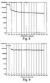
Figure 8 is a graph of change in resistance over an elapsed time period measured in seconds on wetting MLSF001 with distilled water, 1st run; -
Figure 9 is a graph of change in resistance over an elapsed time period measured in seconds on wetting MLSF001 with distilled water, 2nd run; -
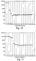
Figure 10 is a graph of change in resistance over an elapsed time period measured in seconds on wetting MLSF001 with 4% saline solution, 1st run; -
Figure 11 is a graph of change in resistance over an elapsed time period measured in seconds on wetting MLSF001 with 4% saline solution, 2nd run; -
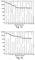
Figure 12 is a graph of change in resistance over an elapsed time period measured in seconds on wetting MLSF002 with distilled water, 1st run; -
Figure 13 is a graph of change in resistance over an elapsed time period measured in seconds on wetting MLSF002 with distilled water, 2nd run; -
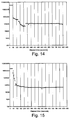
Figure 14 is a graph of change in resistance over an elapsed time period measured in seconds on wetting MLSF002 with 4% saline solution, 1st run; -
Figure 15 is a graph of change in resistance over an elapsed time period measured in seconds on wetting MLSF002 with 4% saline solution, 2nd run; -
Figure 16 is a graph of change in resistance over an elapsed time period measured in seconds on wetting MLSF003 with distilled water, 1st run; -
Figure 17 is a graph of change in resistance over an elapsed time period measured in seconds on wetting MLSF003 with distilled water, 2nd run; -
Figure 18 is a graph of change in resistance over an elapsed time period measured in seconds on wetting MLSF003 with 4% saline solution, 1st run; -
Figure 19 is a graph of change in resistance over an elapsed time period measured in seconds on wetting MLSF003 with 4% saline solution, 2nd run; and -
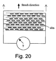
Figure 20 is a schematic circuit diagram similar toFigure 4 but in which the positive and negative conductor tracks are in an expandable sheet that is slitted between tracks to facilitate stretching of the sheet in the direction marked by the arrow. - In the first preferred embodiment, illustrated in
Figure 1 , atransparent cover 3 is provided for themattress 1, with an absorbent under-layer 2 impregnated with a dye that is activated by a body fluid such as urine but not by water vapour. If urine penetrates through the mattress indicators in the dye show through the transparent cover. An indicator specific to urine, or rather specific for organic compounds such as urea or glucose present in urine, is advantageous, since water vapour may be present in the mattress during correct functioning of the cover. Many mattress covers are specified to be "breathable", i.e. they transmit water vapour. Alternatively, a moisture-sensitive dye sensitive to a threshold level of moisture greater than that prevalent as water vapour may be used. - The absorbent layer is here stretchable, suitably being made from a stretchable fabric, eg a crepe-style material, or is incised/ partitioned, in order to minimise perturbation of the cover stretch properties.
- In the second preferred embodiment illustrated in
Figures 2 and3 , threads of electrically conductive silver plated nylon yarn are used forming the warp or weft of a thin flexible woven underlayer 6 of the mattress protector beneath the substantially liquid impermeable shielding layer 5 of the cover. Themattress 4 is fitted with a small microprocessor 7, which monitors the electrical conductivity between neighbouringconductive threads sensing layer 6. In the event of a leak of ionic (electrically conductive) fluid, a short circuit between threads is detected via thethreads - Referring to
Figure 3 , abattery 8 supplies power to the microprocessor 7 as well as supplying positive andnegative threads urine 10 causes a short circuit between the twothreads digital input 11 to the microprocessor 7. This event is stored in the memory of the microprocessor 7. - At some subsequent occasion, the assembly is interrogated by means of a radio wand, the signal of which is picked up by
antenna 14. This causes the microprocessor 7 to respond with an appropriate signal to indicate whether a short has occurred at any time in the past. - This remote interrogation of the microprocessor 7 can take place using conventional RFID technology, without the necessity of removing the mattress cover 5 (so causing a spread of infection), or even the bedclothes.
- In one embodiment, the circuit is completed by the presence of a leak that joins any two or more adjacent lines (weft bars of conductive yarn). The tracks of conductive yarn can be produced in various geometries to provide suitable adjacent positive and negative tracks at appropriate spacings over the mattress surface. An example of this system is illustrated in principle in
figure 4 . - Sample devices were constructed as follows:
- One rectangular piece of conductive-striped fabric was cut from bulk, 250 mm x 260 mm, with longer dimension weft-ways (across width).
- Two rectangular pieces of fusible interfacing were cut from bulk, 250 mm x 30 mm, one fused to each shorter edge of the conductive-striped fabric.
- All four edges of the assembly were over-locked. Rectangular holes were cut out of alternate weft bars one each side (with the sides offset by one bar, creating the circuit as shown above) approximately 14 mm from edge and approximately 13 mm wide. Two lengths of 17 mm wide tape with tinned-copper wire floats were cut 280 mm long. One is stitched in place on each side such that the wire floats contact the weft bars. An overhang of 30 mm is placed at one end to be used for attaching the multimeter.
- The specimens were assessed for their response to distilled water and to a 4% saline solution. The former should indicate the likely behaviour if condensation builds up in the system during use, with an alarm not desirable in this circumstance. The latter should indicate the likely behaviour when urine becomes present in the system as a result of the mattress cover leaking, with an alarm to be triggered.
- Therefore, it is preferable that the sensitivity of the system to distilled water will be much lower than the sensitivity to saline.
- The specimen to be tested was placed on a non-absorbent bench, in an unconditioned lab. The ambient temperature was approximately 19°C for all tests. The terminals at the end of each side of the specimen were connected to a Center SE122 True RMS multimeter, set to measure the resistance of the specimen. This was connected to the serial port of a laptop computer running the SE120 Testlink data collection software. The resistance of the specimen was acquired every two seconds during the test. This data was saved in CSV form (comma separated values) which was then exported to Microsoft Excel for further analysis.
- Two fluids were used for the testing: distilled water and a 4% w/w saline solution (i.e. sodium chloride in distilled water). There are 'recipes' for artificial urine which can be prepared using sodium chloride, potassium chloride, sodium phosphate and urea, plus traces of other chemicals (such as amino acids) but in discussion with ACDS it was decided that the response to saline would be provide sufficient information. Future testing could easily use a more realistic formulation, or samples of actual urine.
- Some initial trials indicated that a total of three drops of each fluid from a disposable pipette was an appropriate volume of fluid to add to specimens of this size. It was calculated that each drop was on average 0.033 ml in volume, so the three drops was approximately 0.1 ml. This is quite a small amount of fluid, so if a useful response can be obtained from the specimens under these conditions it is likely that the system will have the required sensitivity in the final application. The fluid was dropped onto the specimen from approximately 1 cm above the fabric surface.
- The fluid was not placed onto the specimen in one dose. Three one-drop doses were applied one minute apart. This was intended to simulate the more gradual fluid penetration that is likely to occur with a mattress cover leak.
- Before adding the fluid, data recording was carried out for the dry specimen for 30 seconds. The first drop of fluid was added at this stage (t = 30 seconds), with another added 60 seconds after this (t = 90 seconds), and the final drop added after a further 60 seconds (t = 150 seconds). Data was collected continuously over fifteen minutes (end of test at t = 900 seconds), but one-off readings were made ten and twenty minutes after the end of recording (t = 1500 and 2100 seconds, respectively).
- The fluid was placed directly onto a conductive stripe in the fabric. This placement should represent the slowest response that the specimen could provide, as the fluid has to traverse an entire non-conductive stripe to reach an adjacent conductive stripe and trigger a change in resistance. The fastest response could be expected if the drops were placed exactly between the conductive stripes, as only half a non-conductive stripe would need to be traversed to trigger the response in this case.
- Each specimen was tested four times, twice with each of the fluids. The order of test was such that it was unnecessary to carry out any additional processes on the specimen after test, apart from thorough drying. The fabric was not prepared in any way before testing (such as pre-washing, solvent extraction etc.). The order of testing was as follows:

- In theory, the distilled water leaves no residue on the fabric, so any washing or rinsing after each of these tests is redundant. The second saline test is, therefore, carried out on a fabric that has a sodium chloride residue on it, but before carrying out this test it was confirmed that the resistance had increased to a high level. In the absence of moisture, the sodium chloride is non-conductive, as there is no means for ion movement (and hence conduction). If the second test involved placing the drops onto the exact same region as the previous then the effect may be equivalent to having doubled the saline solution concentration. However, each of the four tests was carried out on a different region of the specimen, with no overlap of the (previously) wetted areas.
- The full results for each test on each specimen are illustrated in
Figures 5 to 16 . A summary of the resistance values at key times is provided in Table 1. Note that the 1500 s and 2100 s readings were not made for the final assessment as the basic pattern for these readings had been established. It is also important to note that the maximum measurable resistance for the multimeter being used was 40MΩ, so readings above this limit are recorded as '> 40 M'. Where this is given as the resistance the actual resistance may be much higher - in theory (for a dry specimen with no defects) it will be in the Giga-ohm range (GΩ, 1 x 10⁹ Ω).Table 1. Summary of resistance changes. Specimen Fluid Test No. Resistance at time given 30 s 90 s 150 s 900 s 1500 s 2100 s MLSF001 Distilled water 1 > 40 M 13.0 M 2.67 M 753 k 649 k 639 k 2 > 40 M >40M 6.29 M 5.36 M 4.94 M 4.84 M Saline solution 1 > 40 M > 40 M 390 k 32.1 k 67.4 k 50.1 k 2 9.36 M 9.67 M 9.09 M 48.8 k --- --- MLSF002 Distilled water 1 > 40 M 33.0 M 23.7 M 1.25 M 1.28 M 1.35 M 2 > 40 M > 40 M 19.8 M 1.51 M 1.39 M 2.59 M Saline solution 1 >40M 546 k 217k 87.0 k 104k 112k 2 19.0 M 105 k 80.9 k 48.6 k --- --- MLSF003 Distilled water 1 8.51 M 89.8 k 56.8 k 25.3 k 117 k 141 k 2 >40M 562k 53.8k 75.4k 114k 176k Saline solution 1 14.8 M 4.21 k 694 Ω 2.13 k 2.08 k 2.32 k 2 95.0 k 1.06 k 1.08 k 1.99 k --- --- Key:
M = Mega-ohms (MΩ, 1 x 10⁶ ohms), k = kilo-ohms (kΩ, 1 x 10³ ohms). - In every case, there is a clear difference in behaviour between the different specimens and most importantly, for the two fluids used. It should be noted that the same (logarithmic) scale has been used for all graphs, so that direct comparisons can be made, and any clear differences are in fact likely to be an order of magnitude or more.
- For distilled water, MLSF001 and MLSF002 appear to have similar response times, in that the resistance of each takes approximately the same length of time to start to drop after the drops of fluid are added. This is about 30-90 seconds after fluid is added (t = 60-150 s). MLSF001 seems to have a more abrupt change in resistance when it responds, which is unexpected as the narrower conductive stripe separation of MLSF002 might have been expected to make it respond more quickly. Certainly this is the case for MLSF003, which responds almost instantaneously when the first drop of fluid is added (t ≈ 40 s). For each specimen, the two tests are reasonably similar in behaviour, with roughly the same shape of curve, and resistance values involved. For MLSF001 the change in resistance is by a factor of 53 and 7 for each of the tests, for MLSF002 it is by a factor of 32 and 26 for each of the tests, and for MLSF003 it is by a factor of 340 and 530.
- The magnitude of the resistance drop is much greater for the saline solution, especially for the first of the two tests on each specimen. For the second test, the lowered starting resistance means that although the final resistance is close to that of the first test, the factor by which it has reduced is lower. The response time appears to be proportional to conductive stripe spacing, with MLSF003 faster than MLSF002, which was faster than MLSF001. Only MLSF002 responded noticeably faster with saline solution than with distilled water. For MLSF001 the change in resistance is by a factor of 1200 and 190 for each of the tests, for MLSF002 it is by a factor of 460 and 390 for each of the tests, and for MLSF003 it is by a factor of 6900 and 48.
- It is clear from these results and from
Figures 5 to 16 , that it is easy to distinguish between distilled water and saline solution, even when the specimens have not had any special preparation to ensure that they are free of potentially conductive finishes. If the average of the two distilled water tests and the first saline solution test is compared, the difference in response is nearly two orders of magnitude for MLSF001 (30 c.f. 1200) and well over one order of magnitude for MLSF002 (29 c.f. 460) and MLSF003 (435 c.f. 6900). - Since urine and other body fluids contain substantial quantities of electrolyte, they may be considered analogous to the saline solution in the above tests. This means that the system as described could distinguish between wetting with water and wetting with body fluids such as urine.
- In a further embodiment of the system, positive and negative tracks are provided on opposite sides of the fabric. In this case, electrical continuity between positive and negative tracks is provided as before, when wetting occurs. However, false positives do not occur as a result of wrinkles or folds in the fabric bringing positive and negative tracks together, as may possibly occur when positive and negative tracks occur on the same side of the fabric.
- In a further embodiment of the system, a protective layer of fabric can be applied to cover the electrical tracks, to provide mechanical separation between tracks in the event of creasing or folding. This covering layer may be pervious to fluids, and so still allow electrical continuity between tracks by means of wetting.
- In a further embodiment of the system, the conductive yarns are included in the system as a knitted fabric, rather than a woven fabric. This provides for stretchability of the material, which may be advantageous by causing less perturbation to the pressure-distributive properties of the mattress.
- In a further embodiment, rows of staggered slits may be provided in the woven fabric so as to allow expansion of the material in a similar fashion to lattice pastry or expanded steel mesh. These slits may occur between tracks so as not to interfere with the electrical circuit. The slits would allow expansion and stretchability in the fabric, so causing less perturbation to the pressure-distributive properties.
- In a further embodiment of the invention, soiling of the mattress core, identified as above by means of a recognisable change in electrical characteristics of the device, is immediately transmitted (by means of a radio frequency transmitter situated inside the mattress) to a remote receiver connected to a computer. This may be for example the nurses station, which records the time and location of the adverse event, so that suitable action may be taken. In this embodiment, local interrogation of the mattress is not required, nor is local memory storage within the mattress.
- In a further embodiment, soiling of the mattress identified by the circuit prompts the microcontroller to effect an irreversible change in a visible indicator. The indicator may take the form of a permanently-changed bistable liquid crystal display, visible from the outside of the mattress cover with an appropriate clear window. Alternatively the visible indicator may comprise a combination of a small heating element inside the mattress cover, and an irreversible thermochromic strip in the corresponding place outside the mattress cover. Choosing an appropriate temperature threshold well above body temperature would eliminate false positives due to skin contact. Alternatively, the position of a mechanical flag can be activated irreversibly by means of a solenoid or other mechanical actuator. The position/condition of this flag may be determined by feeling through the mattress cover, without opening the cover. This flag may consist of a shaped memory alloy, which regains a predetermined shape irreversibly when subjected to an electrical stimulus.
- Any of these embodiments obviate the need for electronic memory storage within the mattress, or for radio transmission, while still allowing inspection without opening the mattress cover, to determine whether historical leaks have occurred.
Claims (27)
- A mattress protector to fit over and shield a mattress or mattress core from body fluids, the protector comprising a shielding cover for the mattress or mattress core, the shielding cover having a layer that is impermeable to body fluids that is outermost in use, and a detector within the cover or below or in an under layer of the cover, the detector being below the impermeable layer of the shielding cover, to detect body fluid that has passed into or through the cover, the fluid having penetrated the impermeable layer of the shielding cover.
- A mattress protector as claimed in Claim 1, wherein the cover is a transparent cover for a mattress with an inter-layer or under-layer having a dye that is activated by a body fluid to provide a visual indication of presence of the body fluid.
- A mattress protector as claimed in Claim 2, wherein the dye is not reactive to water vapour.
- A mattress protector as claimed in Claim 3, wherein the dye is specifically reactive to one or more organic compounds in urine, and/or other body fluids.
- A mattress protector as claimed in any preceding claim, wherein the inter-layer or under-layer is absorbent.
- A mattress protector as claimed in any preceding claim, wherein the inter-layer or under-layer is made from a stretchable material.
- A mattress protector as claimed in Claim 1, 5, 6 or 7, wherein the detector comprises electrically conductive material in or associated with the inter-layer or under-layer whereby the detector responds to changes in electrical conductivity to detect body fluid that has passed through the cover
- A mattress protector as claimed in Claim 7, wherein the detector comprises electrically conductive threads or fibres.
- A mattress protector as claimed in Claim 8, wherein the electrically conductive threads or fibres are configured in rows or a matrix over the inter-layer or under-layer.
- A mattress protector as claimed in Claim 8 or 9, wherein the electrically conductive threads form the warp or weft of the inter-layer or under layer.
- A mattress protector as claimed in Claim 8, which further comprises a processor which monitors the electrical conductivity between neighbouring conductive threads so that in the event of a leak of ionic (electrically conductive) fluid into or through the mattress protector, a short circuit between threads will be detected and recorded.
- A mattress protector as claimed in Claim 11, wherein the processor is a microprocessor integrated with the protector and adapted to be interrogated by an external device to determine if any leak events had occurred.
- A mattress protector as claimed in Claim 12, wherein the microprocessor is within or below the cover and is adapted to be interrogated by an inductive link.
- A mattress protector as claimed in any of Claims 7 to 13, wherein positive and negative tracks are provided on opposite sides of the fabric whereby wrinkles or folds in the fabric will not bring positive and negative tracks together.
- A mattress protector as claimed in any of Claims 7 to 13, wherein a protective layer of fabric is applied covering the electrical tracks, to provide mechanical separation between tracks in the event of creasing or folding, the layer being pervious to fluids.
- A mattress protector as claimed in any of Claims 8 to 15, wherein the conductive threads or fibres are included in the system as a knitted fabric, rather than a woven fabric for stretchability of the material.
- A mattress protector as claimed in any of Claims 7 to 16, wherein the protector is of a woven fabric and slits are provided in the woven fabric so as to allow expansion of the material.
- A mattress protector as claimed in any of Claims 7 to 17, wherein when the detector detects body fluid that has passed through the cover a signal is substantially immediately transmitted to a remote receiver connected to a computer.
- A mattress protector as claimed in Claim 18, wherein the protector has a radio frequency transmitter situated inside the mattress to transmit the signal to the receiver.
- A mattress protector as claimed in Claim 18 or 19, wherein the computer is programmed to record the time and location of the event, so that suitable action may be taken.
- A mattress protector as claimed in any of Claims 7 to 20, wherein when the detector detects body fluid that has passed through the cover the circuit prompts a microcontroller to effect an irreversible change in a visible indicator.
- A mattress protector as claimed in Claim 21, wherein the visible indicator is visible from the outside of the mattress cover via an appropriate clear window.
- A mattress protector as claimed in Claim 21, wherein the visible indicator comprises a combination of a small heating element inside the mattress cover, and an irreversible thermochromic strip in the corresponding place outside the mattress cover.
- A mattress protector as claimed in any of Claims 7 to 23, wherein the position of a mechanical flag can be activated irreversibly by means of a solenoid or other mechanical actuator and the position/condition of this flag may be determined by feeling through the mattress cover, without opening the cover.
- A mattress protector as claimed in Claim 24, wherein the flag is formed of a shaped memory alloy, which regains a predetermined shape irreversibly when subjected to an electrical stimulus.
- A mattress protector as claimed in any preceding claim in combination with a mattress.
- A mattress core encased in a mattress protector of any of Claims 1 to 13.
Applications Claiming Priority (2)
| Application Number | Priority Date | Filing Date | Title |
|---|---|---|---|
| GB0327138A GB2408204B (en) | 2003-11-21 | 2003-11-21 | Mattress protection |
| PCT/GB2004/004942 WO2005051134A1 (en) | 2003-11-21 | 2004-11-22 | Mattress protection |
Publications (2)
| Publication Number | Publication Date |
|---|---|
| EP1684615A1 EP1684615A1 (en) | 2006-08-02 |
| EP1684615B1 true EP1684615B1 (en) | 2010-02-24 |
Family
ID=29764236
Family Applications (1)
| Application Number | Title | Priority Date | Filing Date |
|---|---|---|---|
| EP04798649A Expired - Lifetime EP1684615B1 (en) | 2003-11-21 | 2004-11-22 | Mattress protection |
Country Status (10)
| Country | Link |
|---|---|
| US (1) | US20070277323A1 (en) |
| EP (1) | EP1684615B1 (en) |
| JP (1) | JP2007511314A (en) |
| AT (1) | ATE458427T1 (en) |
| AU (1) | AU2004292406A1 (en) |
| BR (1) | BRPI0416728A (en) |
| CA (1) | CA2544641A1 (en) |
| DE (1) | DE602004025724D1 (en) |
| GB (1) | GB2408204B (en) |
| WO (1) | WO2005051134A1 (en) |
Cited By (8)
| Publication number | Priority date | Publication date | Assignee | Title |
|---|---|---|---|---|
| US10022277B2 (en) | 2013-03-13 | 2018-07-17 | Hill-Rom Services, Inc. | Methods and apparatus for the detection of moisture and multifunctional sensor systems |
| US10115291B2 (en) | 2016-04-26 | 2018-10-30 | Hill-Rom Services, Inc. | Location-based incontinence detection |
| US10159607B2 (en) | 2015-11-16 | 2018-12-25 | Hill-Rom Services, Inc. | Incontinence detection apparatus |
| US10653567B2 (en) | 2015-11-16 | 2020-05-19 | Hill-Rom Services, Inc. | Incontinence detection pad validation apparatus and method |
| US10716715B2 (en) | 2017-08-29 | 2020-07-21 | Hill-Rom Services, Inc. | RFID tag inlay for incontinence detection pad |
| US11707387B2 (en) | 2015-11-16 | 2023-07-25 | Hill-Rom Services, Inc. | Incontinence detection method |
| US11950987B2 (en) | 2019-05-21 | 2024-04-09 | Hill-Rom Services, Inc. | Manufacturing method for incontinence detection pads having wireless communication capability |
| US20260000215A1 (en) * | 2024-06-27 | 2026-01-01 | Umano Medical Inc. | Cover for a support surface |
Families Citing this family (20)
| Publication number | Priority date | Publication date | Assignee | Title |
|---|---|---|---|---|
| DE602007012999D1 (en) | 2006-01-07 | 2011-04-21 | Arthur Koblasz | USE OF RFID TO PREVENT OR DETECT SCORES, BREAKS, BEDDING, AND MEDICAL FAULTS |
| WO2010015630A1 (en) * | 2008-08-04 | 2010-02-11 | Asap-Norway As | Fluid absorbing sheet |
| DE102009020560B4 (en) | 2009-05-08 | 2012-11-22 | Nordenia Deutschland Lohne Gmbh | Mattress cover and material web for this |
| CN102395718B (en) * | 2009-07-13 | 2013-12-25 | 精密结构集团有限公司 | Improved fabric for preventing and reducing skin wounds |
| WO2011049744A2 (en) * | 2009-10-20 | 2011-04-28 | Stryker Corporation | Microclimate management system |
| US8826473B2 (en) | 2011-07-19 | 2014-09-09 | Hill-Rom Services, Inc. | Moisture detection system |
| EP2750652B1 (en) * | 2011-08-30 | 2015-09-23 | Eswell AS | A positioning system |
| US9332855B2 (en) * | 2014-03-13 | 2016-05-10 | John Robert BAXTER | Personal cellular tissue repair, recovery and regeneration enhancement sleep system |
| USD776960S1 (en) * | 2015-04-17 | 2017-01-24 | Casper Sleep Inc. | Mattress |
| US9691516B2 (en) * | 2015-06-30 | 2017-06-27 | John R Baxter | Personal electromagnetic hygiene sleep system |
| USD799858S1 (en) * | 2016-03-10 | 2017-10-17 | Purple Innovation, Llc | Mattress cushion |
| US20180146906A1 (en) | 2016-11-29 | 2018-05-31 | Hill-Rom Services, Inc. | System and method for determining incontinence device replacement interval |
| CN112203581B (en) * | 2018-05-30 | 2024-07-30 | 美梦有限公司 | Monitoring methods and buffer structures |
| US20200015752A1 (en) * | 2018-07-13 | 2020-01-16 | John R Baxter | Textile utilizing carbon nanotubes |
| FR3099044B1 (en) | 2019-07-23 | 2022-10-14 | Winncare France | SYSTEM AND METHOD FOR DETECTING THE INCONTINENCE OF BED-BED PERSONS |
| US12048613B2 (en) | 2019-09-30 | 2024-07-30 | Hill-Rom Services, Inc. | Incontinence detection system |
| US11712186B2 (en) | 2019-09-30 | 2023-08-01 | Hill-Rom Services, Inc. | Incontinence detection with real time location information |
| USD1004342S1 (en) | 2021-04-20 | 2023-11-14 | Purple Innovation, Llc | Mattress cover |
| USD1002242S1 (en) | 2021-04-20 | 2023-10-24 | Purple Innovation, Llc | Mattress cover |
| USD999569S1 (en) | 2021-04-20 | 2023-09-26 | Purple Innovation, Llc | Mattress cover |
Family Cites Families (17)
| Publication number | Priority date | Publication date | Assignee | Title |
|---|---|---|---|---|
| US3384908A (en) * | 1965-04-15 | 1968-05-28 | Wortso Corp | Bedding cover |
| US3778570A (en) * | 1972-10-05 | 1973-12-11 | J Shuman | Enuresis bed pad |
| GB1555310A (en) * | 1976-05-21 | 1979-11-07 | Medtron Electronics Pty Ltd | Enuresis detector pad having a printed electric circuit element |
| US5137033A (en) * | 1991-07-15 | 1992-08-11 | Norton John L | Patient monitoring device |
| US5291181A (en) * | 1992-03-30 | 1994-03-01 | Deponte Dominic A | Wet bed alarm and temperature monitoring system |
| EP0727975A1 (en) * | 1992-11-13 | 1996-08-28 | MITCHELL, Winalee G. | Absorbent including super absorbent and capacity monitor |
| US5575025A (en) * | 1994-11-14 | 1996-11-19 | Peters; Michael J. | Gurney with protective cover |
| GB2300806A (en) * | 1995-05-01 | 1996-11-20 | Tilly Christie | Liquid absorbent bedding |
| US6341393B1 (en) * | 1995-09-13 | 2002-01-29 | Ergodyne Corporation | Patient transfer and repositioning system |
| GB2310493B (en) * | 1996-02-26 | 2000-08-02 | Unilever Plc | Determination of the characteristics of fluid |
| JPH1020789A (en) * | 1996-07-04 | 1998-01-23 | Kishiko Kamiyama | Emblem for informing change of bedclothes and nightclothes |
| WO1998012997A1 (en) * | 1996-09-25 | 1998-04-02 | Oppenhejm & Jansson Aps | A transducer pad comprising a sensor for detecting enuresis nocturna, sheets comprising the transducer pad, methods of producing the transducer pad and the sheets, and use thereof |
| AU4274299A (en) * | 1998-06-03 | 1999-12-20 | Paul Kimsey | Moisture detector |
| NL1013012C2 (en) * | 1999-09-09 | 2001-03-12 | Tno | Sensor for detecting the presence of moisture. |
| EP1138293B1 (en) * | 2000-03-25 | 2012-07-18 | The Procter & Gamble Company | Transparent absorbing article |
| US7038588B2 (en) * | 2001-05-04 | 2006-05-02 | Draeger Medical Infant Care, Inc. | Apparatus and method for patient point-of-care data management |
| US6618880B1 (en) * | 2002-06-27 | 2003-09-16 | Fabrictech 2000 Llc | Mattress cover with expandable sidewalls |
-
2003
- 2003-11-21 GB GB0327138A patent/GB2408204B/en not_active Expired - Fee Related
-
2004
- 2004-11-22 WO PCT/GB2004/004942 patent/WO2005051134A1/en not_active Ceased
- 2004-11-22 US US10/580,086 patent/US20070277323A1/en not_active Abandoned
- 2004-11-22 BR BRPI0416728-7A patent/BRPI0416728A/en not_active Application Discontinuation
- 2004-11-22 CA CA002544641A patent/CA2544641A1/en not_active Abandoned
- 2004-11-22 AT AT04798649T patent/ATE458427T1/en not_active IP Right Cessation
- 2004-11-22 EP EP04798649A patent/EP1684615B1/en not_active Expired - Lifetime
- 2004-11-22 JP JP2006540604A patent/JP2007511314A/en active Pending
- 2004-11-22 AU AU2004292406A patent/AU2004292406A1/en not_active Abandoned
- 2004-11-22 DE DE602004025724T patent/DE602004025724D1/en not_active Expired - Lifetime
Cited By (14)
| Publication number | Priority date | Publication date | Assignee | Title |
|---|---|---|---|---|
| US10973701B2 (en) | 2013-03-13 | 2021-04-13 | Hill-Rom Services, Inc. | Apparatus for the detection of moisture |
| US12138142B2 (en) | 2013-03-13 | 2024-11-12 | Hill-Rom Services, Inc. | Apparatus for the detection of moisture |
| US11331227B2 (en) | 2013-03-13 | 2022-05-17 | Hill-Rom Services, Inc. | Apparatus for the detection of moisture |
| US10022277B2 (en) | 2013-03-13 | 2018-07-17 | Hill-Rom Services, Inc. | Methods and apparatus for the detection of moisture and multifunctional sensor systems |
| US10350116B2 (en) | 2015-11-16 | 2019-07-16 | Hill-Rom Services, Inc. | Incontinence detection apparatus electrical architecture |
| US10653567B2 (en) | 2015-11-16 | 2020-05-19 | Hill-Rom Services, Inc. | Incontinence detection pad validation apparatus and method |
| US10159607B2 (en) | 2015-11-16 | 2018-12-25 | Hill-Rom Services, Inc. | Incontinence detection apparatus |
| US11707387B2 (en) | 2015-11-16 | 2023-07-25 | Hill-Rom Services, Inc. | Incontinence detection method |
| US10115291B2 (en) | 2016-04-26 | 2018-10-30 | Hill-Rom Services, Inc. | Location-based incontinence detection |
| US10716715B2 (en) | 2017-08-29 | 2020-07-21 | Hill-Rom Services, Inc. | RFID tag inlay for incontinence detection pad |
| US11020284B2 (en) | 2017-08-29 | 2021-06-01 | Hill-Rom Services, Inc. | Incontinence detection pad with liquid filter layer |
| US11478383B2 (en) | 2017-08-29 | 2022-10-25 | Hill-Rom Services, Inc. | Incontinence detection pad having redundant electrical paths to an RFID tag |
| US11950987B2 (en) | 2019-05-21 | 2024-04-09 | Hill-Rom Services, Inc. | Manufacturing method for incontinence detection pads having wireless communication capability |
| US20260000215A1 (en) * | 2024-06-27 | 2026-01-01 | Umano Medical Inc. | Cover for a support surface |
Also Published As
| Publication number | Publication date |
|---|---|
| WO2005051134A1 (en) | 2005-06-09 |
| AU2004292406A1 (en) | 2005-06-09 |
| BRPI0416728A (en) | 2007-01-16 |
| DE602004025724D1 (en) | 2010-04-08 |
| GB0327138D0 (en) | 2003-12-24 |
| ATE458427T1 (en) | 2010-03-15 |
| GB2408204B (en) | 2005-11-23 |
| CA2544641A1 (en) | 2005-06-09 |
| JP2007511314A (en) | 2007-05-10 |
| EP1684615A1 (en) | 2006-08-02 |
| GB2408204A (en) | 2005-05-25 |
| US20070277323A1 (en) | 2007-12-06 |
Similar Documents
| Publication | Publication Date | Title |
|---|---|---|
| US20070277323A1 (en) | Mattress Protection | |
| JP6180939B2 (en) | Tool for analyzing liquid waste data in an absorber, an absorber adapted to collect liquid waste data, and a control unit that interacts with the absorber to collect liquid waste data | |
| EP3685811B1 (en) | Urine-detection device with adhesive tape and emitter sensor | |
| EP2654646B1 (en) | Absorbent article comprising a liquid discharge sensor | |
| US5291181A (en) | Wet bed alarm and temperature monitoring system | |
| KR102099784B1 (en) | Absorbent article leak detection clothing and absorbent article leak detection method using the same | |
| US8169329B2 (en) | Fluid detecting mattress cover and monitoring system | |
| US3864676A (en) | Moisture detector | |
| US9526439B2 (en) | Wound dressings and performance measurement of such dressings | |
| US5903222A (en) | Wet garment detector | |
| CA3008224C (en) | Wearable absorbent article | |
| US3759246A (en) | Incontinence measurement sensor | |
| CA2361132C (en) | Wetness monitoring system | |
| JP4556189B2 (en) | Functional clothing, especially NBC protective clothing with integrated measuring equipment | |
| US20130324955A1 (en) | Wearable articles with wetness sensing | |
| US20170112681A1 (en) | Body fluid sensor pad | |
| US20200253528A1 (en) | System and method for determining incontinence device replacement interval | |
| TW201700078A (en) | Personal hygiene product with a digital element | |
| JP6401642B2 (en) | Residual urine volume measurement support system | |
| AU2013408433B2 (en) | Method for monitoring excrement data | |
| KR20210095917A (en) | A system comprising a wearable absorbent hygiene product and a hygiene monitoring device | |
| US20250205090A1 (en) | Absorbent article with leakage probability algorithm | |
| Fader et al. | Review of methods used for quantifying excess water in over‐hydrated skin using evaporimetry | |
| CN119698268A (en) | Sensor arrangement for sensing the filling state of an absorbent article |
Legal Events
| Date | Code | Title | Description |
|---|---|---|---|
| PUAI | Public reference made under article 153(3) epc to a published international application that has entered the european phase |
Free format text: ORIGINAL CODE: 0009012 |
|
| 17P | Request for examination filed |
Effective date: 20060524 |
|
| AK | Designated contracting states |
Kind code of ref document: A1 Designated state(s): AT BE BG CH CY CZ DE DK EE ES FI FR GB GR HU IE IS IT LI LU MC NL PL PT RO SE SI SK TR |
|
| DAX | Request for extension of the european patent (deleted) | ||
| GRAP | Despatch of communication of intention to grant a patent |
Free format text: ORIGINAL CODE: EPIDOSNIGR1 |
|
| RIN1 | Information on inventor provided before grant (corrected) |
Inventor name: PELL, MARTIN, FERGUSON Inventor name: NICHOLSON, GRAHAM Inventor name: BAIN, DUNCAN |
|
| RAP1 | Party data changed (applicant data changed or rights of an application transferred) |
Owner name: UCL BUSINESS PLC |
|
| GRAS | Grant fee paid |
Free format text: ORIGINAL CODE: EPIDOSNIGR3 |
|
| GRAA | (expected) grant |
Free format text: ORIGINAL CODE: 0009210 |
|
| AK | Designated contracting states |
Kind code of ref document: B1 Designated state(s): AT BE BG CH CY CZ DE DK EE ES FI FR GB GR HU IE IS IT LI LU MC NL PL PT RO SE SI SK TR |
|
| REG | Reference to a national code |
Ref country code: GB Ref legal event code: FG4D |
|
| REG | Reference to a national code |
Ref country code: CH Ref legal event code: EP |
|
| REG | Reference to a national code |
Ref country code: IE Ref legal event code: FG4D |
|
| REF | Corresponds to: |
Ref document number: 602004025724 Country of ref document: DE Date of ref document: 20100408 Kind code of ref document: P |
|
| REG | Reference to a national code |
Ref country code: NL Ref legal event code: VDEP Effective date: 20100224 |
|
| PG25 | Lapsed in a contracting state [announced via postgrant information from national office to epo] |
Ref country code: IS Free format text: LAPSE BECAUSE OF FAILURE TO SUBMIT A TRANSLATION OF THE DESCRIPTION OR TO PAY THE FEE WITHIN THE PRESCRIBED TIME-LIMIT Effective date: 20100624 Ref country code: PT Free format text: LAPSE BECAUSE OF FAILURE TO SUBMIT A TRANSLATION OF THE DESCRIPTION OR TO PAY THE FEE WITHIN THE PRESCRIBED TIME-LIMIT Effective date: 20100625 |
|
| PG25 | Lapsed in a contracting state [announced via postgrant information from national office to epo] |
Ref country code: FI Free format text: LAPSE BECAUSE OF FAILURE TO SUBMIT A TRANSLATION OF THE DESCRIPTION OR TO PAY THE FEE WITHIN THE PRESCRIBED TIME-LIMIT Effective date: 20100224 Ref country code: SI Free format text: LAPSE BECAUSE OF FAILURE TO SUBMIT A TRANSLATION OF THE DESCRIPTION OR TO PAY THE FEE WITHIN THE PRESCRIBED TIME-LIMIT Effective date: 20100224 Ref country code: PL Free format text: LAPSE BECAUSE OF FAILURE TO SUBMIT A TRANSLATION OF THE DESCRIPTION OR TO PAY THE FEE WITHIN THE PRESCRIBED TIME-LIMIT Effective date: 20100224 Ref country code: AT Free format text: LAPSE BECAUSE OF FAILURE TO SUBMIT A TRANSLATION OF THE DESCRIPTION OR TO PAY THE FEE WITHIN THE PRESCRIBED TIME-LIMIT Effective date: 20100224 |
|
| PG25 | Lapsed in a contracting state [announced via postgrant information from national office to epo] |
Ref country code: SE Free format text: LAPSE BECAUSE OF FAILURE TO SUBMIT A TRANSLATION OF THE DESCRIPTION OR TO PAY THE FEE WITHIN THE PRESCRIBED TIME-LIMIT Effective date: 20100224 Ref country code: RO Free format text: LAPSE BECAUSE OF FAILURE TO SUBMIT A TRANSLATION OF THE DESCRIPTION OR TO PAY THE FEE WITHIN THE PRESCRIBED TIME-LIMIT Effective date: 20100224 Ref country code: NL Free format text: LAPSE BECAUSE OF FAILURE TO SUBMIT A TRANSLATION OF THE DESCRIPTION OR TO PAY THE FEE WITHIN THE PRESCRIBED TIME-LIMIT Effective date: 20100224 Ref country code: GR Free format text: LAPSE BECAUSE OF FAILURE TO SUBMIT A TRANSLATION OF THE DESCRIPTION OR TO PAY THE FEE WITHIN THE PRESCRIBED TIME-LIMIT Effective date: 20100525 Ref country code: ES Free format text: LAPSE BECAUSE OF FAILURE TO SUBMIT A TRANSLATION OF THE DESCRIPTION OR TO PAY THE FEE WITHIN THE PRESCRIBED TIME-LIMIT Effective date: 20100604 Ref country code: EE Free format text: LAPSE BECAUSE OF FAILURE TO SUBMIT A TRANSLATION OF THE DESCRIPTION OR TO PAY THE FEE WITHIN THE PRESCRIBED TIME-LIMIT Effective date: 20100224 Ref country code: CY Free format text: LAPSE BECAUSE OF FAILURE TO SUBMIT A TRANSLATION OF THE DESCRIPTION OR TO PAY THE FEE WITHIN THE PRESCRIBED TIME-LIMIT Effective date: 20100224 Ref country code: BE Free format text: LAPSE BECAUSE OF FAILURE TO SUBMIT A TRANSLATION OF THE DESCRIPTION OR TO PAY THE FEE WITHIN THE PRESCRIBED TIME-LIMIT Effective date: 20100224 |
|
| PG25 | Lapsed in a contracting state [announced via postgrant information from national office to epo] |
Ref country code: BG Free format text: LAPSE BECAUSE OF FAILURE TO SUBMIT A TRANSLATION OF THE DESCRIPTION OR TO PAY THE FEE WITHIN THE PRESCRIBED TIME-LIMIT Effective date: 20100524 Ref country code: SK Free format text: LAPSE BECAUSE OF FAILURE TO SUBMIT A TRANSLATION OF THE DESCRIPTION OR TO PAY THE FEE WITHIN THE PRESCRIBED TIME-LIMIT Effective date: 20100224 Ref country code: CZ Free format text: LAPSE BECAUSE OF FAILURE TO SUBMIT A TRANSLATION OF THE DESCRIPTION OR TO PAY THE FEE WITHIN THE PRESCRIBED TIME-LIMIT Effective date: 20100224 |
|
| PLBE | No opposition filed within time limit |
Free format text: ORIGINAL CODE: 0009261 |
|
| STAA | Information on the status of an ep patent application or granted ep patent |
Free format text: STATUS: NO OPPOSITION FILED WITHIN TIME LIMIT |
|
| PG25 | Lapsed in a contracting state [announced via postgrant information from national office to epo] |
Ref country code: DK Free format text: LAPSE BECAUSE OF FAILURE TO SUBMIT A TRANSLATION OF THE DESCRIPTION OR TO PAY THE FEE WITHIN THE PRESCRIBED TIME-LIMIT Effective date: 20100224 |
|
| 26N | No opposition filed |
Effective date: 20101125 |
|
| PG25 | Lapsed in a contracting state [announced via postgrant information from national office to epo] |
Ref country code: IT Free format text: LAPSE BECAUSE OF FAILURE TO SUBMIT A TRANSLATION OF THE DESCRIPTION OR TO PAY THE FEE WITHIN THE PRESCRIBED TIME-LIMIT Effective date: 20100224 |
|
| PGFP | Annual fee paid to national office [announced via postgrant information from national office to epo] |
Ref country code: GB Payment date: 20101126 Year of fee payment: 7 |
|
| PG25 | Lapsed in a contracting state [announced via postgrant information from national office to epo] |
Ref country code: MC Free format text: LAPSE BECAUSE OF NON-PAYMENT OF DUE FEES Effective date: 20101130 |
|
| REG | Reference to a national code |
Ref country code: CH Ref legal event code: PL |
|
| PG25 | Lapsed in a contracting state [announced via postgrant information from national office to epo] |
Ref country code: LI Free format text: LAPSE BECAUSE OF NON-PAYMENT OF DUE FEES Effective date: 20101130 Ref country code: CH Free format text: LAPSE BECAUSE OF NON-PAYMENT OF DUE FEES Effective date: 20101130 |
|
| REG | Reference to a national code |
Ref country code: FR Ref legal event code: ST Effective date: 20110801 |
|
| REG | Reference to a national code |
Ref country code: DE Ref legal event code: R119 Ref document number: 602004025724 Country of ref document: DE Effective date: 20110601 Ref country code: DE Ref legal event code: R119 Ref document number: 602004025724 Country of ref document: DE Effective date: 20110531 |
|
| PG25 | Lapsed in a contracting state [announced via postgrant information from national office to epo] |
Ref country code: FR Free format text: LAPSE BECAUSE OF NON-PAYMENT OF DUE FEES Effective date: 20101130 Ref country code: IE Free format text: LAPSE BECAUSE OF NON-PAYMENT OF DUE FEES Effective date: 20101122 |
|
| GBPC | Gb: european patent ceased through non-payment of renewal fee |
Effective date: 20111122 |
|
| PG25 | Lapsed in a contracting state [announced via postgrant information from national office to epo] |
Ref country code: HU Free format text: LAPSE BECAUSE OF FAILURE TO SUBMIT A TRANSLATION OF THE DESCRIPTION OR TO PAY THE FEE WITHIN THE PRESCRIBED TIME-LIMIT Effective date: 20100825 Ref country code: LU Free format text: LAPSE BECAUSE OF NON-PAYMENT OF DUE FEES Effective date: 20101122 |
|
| PG25 | Lapsed in a contracting state [announced via postgrant information from national office to epo] |
Ref country code: GB Free format text: LAPSE BECAUSE OF NON-PAYMENT OF DUE FEES Effective date: 20111122 Ref country code: TR Free format text: LAPSE BECAUSE OF FAILURE TO SUBMIT A TRANSLATION OF THE DESCRIPTION OR TO PAY THE FEE WITHIN THE PRESCRIBED TIME-LIMIT Effective date: 20100224 |
|
| PG25 | Lapsed in a contracting state [announced via postgrant information from national office to epo] |
Ref country code: DE Free format text: LAPSE BECAUSE OF NON-PAYMENT OF DUE FEES Effective date: 20110531 |