EP1684611B1 - Compression system for backpack - Google Patents
Compression system for backpack Download PDFInfo
- Publication number
- EP1684611B1 EP1684611B1 EP04800470A EP04800470A EP1684611B1 EP 1684611 B1 EP1684611 B1 EP 1684611B1 EP 04800470 A EP04800470 A EP 04800470A EP 04800470 A EP04800470 A EP 04800470A EP 1684611 B1 EP1684611 B1 EP 1684611B1
- Authority
- EP
- European Patent Office
- Prior art keywords
- backpack
- junction
- strap
- backpack body
- shoulder straps
- Prior art date
- Legal status (The legal status is an assumption and is not a legal conclusion. Google has not performed a legal analysis and makes no representation as to the accuracy of the status listed.)
- Expired - Lifetime
Links
Images





Classifications
-
- A—HUMAN NECESSITIES
- A45—HAND OR TRAVELLING ARTICLES
- A45F—TRAVELLING OR CAMP EQUIPMENT: SACKS OR PACKS CARRIED ON THE BODY
- A45F3/00—Travelling or camp articles; Sacks or packs carried on the body
- A45F3/04—Sacks or packs carried on the body by means of two straps passing over the two shoulders
- A45F3/047—Sacks or packs carried on the body by means of two straps passing over the two shoulders with adjustable fastenings for the shoulder straps or waist belts
-
- A—HUMAN NECESSITIES
- A45—HAND OR TRAVELLING ARTICLES
- A45C—PURSES; LUGGAGE; HAND CARRIED BAGS
- A45C7/00—Collapsible or extensible purses, luggage, bags or the like
- A45C7/0059—Flexible luggage; Hand bags
- A45C7/0077—Flexible luggage; Hand bags collapsible to a minimal configuration, e.g. for storage purposes
-
- A—HUMAN NECESSITIES
- A45—HAND OR TRAVELLING ARTICLES
- A45C—PURSES; LUGGAGE; HAND CARRIED BAGS
- A45C5/00—Rigid or semi-rigid luggage
- A45C5/06—Rigid or semi-rigid luggage with outside compartments
-
- A—HUMAN NECESSITIES
- A45—HAND OR TRAVELLING ARTICLES
- A45F—TRAVELLING OR CAMP EQUIPMENT: SACKS OR PACKS CARRIED ON THE BODY
- A45F3/00—Travelling or camp articles; Sacks or packs carried on the body
- A45F3/04—Sacks or packs carried on the body by means of two straps passing over the two shoulders
Definitions
- This invention relates generally to backpacks, and, in particular, to backpacks having compression systems that compress the contents of the backpack and minimize stresses presented to the wearer.
- Frameless backpacks rely on shoulder straps, and, optionally, hip straps, to carry the load. These backpacks are used for day hiking and other outdoor recreational activities, as well as by students for carrying books and supplies between school and home. Many students today need to carry more books and supplies than they have in the past due to the emphasis being placed on improving schools and the quality of education afforded young people, resulting in heavy loads being carried in the students' backpacks.
- a backpack with standard shoulder straps primarily carries the load on the shoulders. However, the more a load can ride on the hips, the less load pressure there is on the shoulders. Further, the closer the load is to the back of the user, the more upright the user is able to walk, and, consequently, there is less pressure on the hip joints.
- the load in the backpack is compressed, it has less tendency to shift around when the user is moving, jumping, or bending over.
- the more a load moves the more the body has to work and move to compensate for the load shifting.
- U.S. Patent No. 6,164,509 to Gausling et al discloses a backpack with a shoulder strap secured at one end to a top edge of a body side panel of the backpack.
- the strap extends across a lower portion of a lateral side of the backpack, and is secured to the backpack at a junction between the lateral side and an outer side of the backpack.
- Another strap is connected at its first end to the shoulder strap, extends beneath the backpack body, and is connected at its other end to a junction between the bottom of the backpack body and the outer side of the backpack body.
- the weight of the contents of the backpack act to compress the outer side of the backpack body toward the body when the back is placed on a user's shoulders, thereby shifting the weight closer to the user's back.
- Gausling is limiting in that it has a complicated construction requiring excessive straps, and, therefore, one that has increased manufacturing costs and potential for functional and maintenance problems.
- the present invention is directed to a backpack with a compression system that is efficient and effective in minimizing the stresses presented to a wearer using a loaded backpack, and, therefore, allows the wearer to carry heavier loads for a longer period of time with reduced fatigue and discomfort.
- a backpack with a compression system includes a backpack body having a top side, a bottom side, two lateral sides, a body side, an outer side, and a pair of shoulder straps.
- Each shoulder strap has a first end connected at a junction of the top side and the body side, and a second end connected to the backpack body at a junction of the bottom side and the body side.
- the straps extend along a corresponding lateral side and the bottom of the backpack body, and are slidably connected to the backpack body at a junction of the body side and a corresponding lateral side, and at a junction of the corresponding lateral side and the outer side.
- a backpack with a compression system includes a backpack body having a top side, a bottom side, two lateral sides, a body side, an outer side, and a compression assembly.
- the compression assembly includes a pair of shoulder straps and a compression member.
- Each shoulder strap has a first end connected at a junction of the top side and the body side, and a second end connected to the backpack body at a junction of the bottom side and the body side.
- the straps extend along a corresponding lateral side and the bottom of the backpack body, and are slidably connected to the backpack body at a junction of the body side and a corresponding lateral side, and at a junction of the corresponding lateral side and the outer side.
- the compression member is positioned adjacent an outer surface of the outer side and is secured to each of the shoulder straps.
- a backpack with a compression system includes a backpack body having a top side, a bottom side, two lateral sides, a body side and an outer side, and a pair of shoulder straps.
- Each shoulder strap has a first end connected at a junction of the top side and the body side, and a second end connected to the backpack body at a junction of the bottom side and the body side.
- Each shoulder strap extends along a corresponding lateral side and the bottom of the backpack body, and is slidably connected to the backpack body at a junction of the body side and a corresponding lateral side, and at a junction of the corresponding lateral side and the outer side such that the lateral sides will automatically compress and a portion of each shoulder strap between the first end and the junction of the body side and the corresponding lateral side will lengthen when the loaded backpack is lifted.
- Substantial advantage is achieved by providing a backpack with a compression system as described herein.
- a backpack with a compression system automatically compresses the load in the pack, shifting the load closer to the wearer's lower back and hips.
- a backpack maximizes wearer comfort and health, even when the pack is fully loaded.
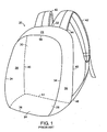
- FIG. 1 A typical backpack body 20 of the prior art is shown in FIG. 1 , and is formed by a number of panels or sides.
- the reference numbers used for many of the elements of backpack body 20 are used for similar or identical components of preferred embodiments of the present invention described below.
- Backpack body 20 has a top side or region 22, a bottom side or region 24, two lateral sides or regions 26, an outer side or region 28, and a body side or region 30. Separating the various panels or side regions is a series of junctions or seams. When connected, these six panel regions define an interior compartment in backpack body 20 into which cargo such as books, food, clothing, etc. may be stowed. Of course; this interior compartment may be subdivided into, or complemented with, a number of additional compartments or regions for keeping various items separate. This allows a user to more efficiently pack and organize the backpack, which can provide for better access to important items, as well as distribute the load properly in the backpack. Although such a six-panel configuration is not necessary, it is helpful in helping to describe the features and advantages of the present invention.
- backpack body 20 can comprise fewer panels or sides, and have correspondingly fewer seams or junctions, and be within the scope of the invention.
- the body, top, bottom, outer, and lateral sides could be formed of one continuous piece of fabric with no actual seams or junctions, and such a construction is to be considered within the scope of the present invention.
- backpack body 20 could still be described as having a number of seams or junctions, which would aid in understanding the relative location on backpack body 20 being discussed.
- backpack body 20 could have more than six panels or sides and corresponding seams or junctions, and such a configuration is also considered to be within the scope of the invention.
- a first junction 32 is defined between top panel 22 and body side 30.
- Second junctions 34 are similarly disposed in the regions between the outer side 28 and the two lateral sides 26.
- a third junction 36 defines a transition region between the bottom panel 24 and the outer side 28, and a fourth junction 38 is disposed generally between the outer side 28 and the top panel or side 22.
- Fifth junctions 40 are disposed between lateral sides 26 and body side 30.
- Sixth junctions 41 are disposed between body side 30 and bottom panel 24.
- first junction 32 between top side 22 and body side 30 is meant only to define a general region of transition between these two sides 22 and 30.
- junctions can comprise a general transition region from one section of backpack body 20 to another without any discontinuity in the panel or side.
- a junction can generally define a region where the panels or sides transition from one orientation to another, particularly when backpack body 20 is loaded with contents.
- a junction can be merely a bend in backpack body 20.
- junctions can be a distinct part of backpack body 20, such as a seam formed by sewing, or any other type of permanent bonding or fusing of the two sides.
- a junction can be a temporary seam along or near which a body compartment can be opened and closed.
- a junction can represent an area near a nylon or metal zipper, a hook and loop-type fastener, snaps, buttons, and the like.
- backpack body 20 defines a compartment into which cargo such as books, clothing, food, etc. may be placed, additional compartments and features such as outer and side compartments, loops, etc. may be added to backpack body 20.
- a pair of shoulder straps 42 are secured at first ends 44 thereof to backpack body 20 proximate first junction 32 (hidden from view here) by stitching or other suitable means.
- a second end 46 of each shoulder strap 42 is secured by stitching or other suitable means to fifth junction 40 proximate a lower end of backpack body 20.
- Shoulder straps 42 serve to support the weight of the backpack on the shoulders of the user in known fashion.
- the panels making up backpack body 20, as well as the straps and other components of the invention can variously comprise a number of natural or synthetic materials.
- Natural fabric such as leather, cotton and the like may be useful for certain applications.
- synthetic fabrics made from thermoplastic materials such as polypropylene, polyvinyl chloride, polyamide (such as nylon), polyethylene, polyester, etc.
- nylon that can be textured for breathability, wear-resistance, and waterproofed with materials such as silicone elastomers and the like.
- Particularly useful is a type of nylon known as Cordura (supplied by E.I. du Pont de Nemours & Co. of Wilmington, Del.).
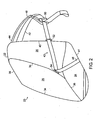
- shoulder straps 42 may be provided with padding 48 to improve the comfort and fit for the user.
- Shoulder straps 42 may also be provided with an adjustable buckle 50.
- the configuration of buckle 50 requires shoulder strap 42 to be formed of two pieces. It is to be appreciated that a shoulder strap, or any other strap described herein, such as a hip strap, formed of more than one piece is considered to be, along with any associated buckle or other adjustable fastener, an integral strap within the scope of the present invention.
- Shoulder strap 42 is connected at its first end 44 to backpack body 20 proximate first junction 32. Second end 46 of shoulder strap 42 is connected to backpack body 20 proximate sixth junction 41. Between first end 44 and second end 46, shoulder strap 42 extends along lateral side 26 of backpack body 20 from fifth junction 40 across to second junction 34, and back across bottom panel 24 to sixth junction 41. In a preferred embodiment, shoulder strap 42 is slidably connected to backpack body 20 at fifth junction 40 and second junction 34. In a preferred embodiment, the location at which shoulder strap 42 is slidably connected at fifth junction 40 is at a higher position than the location at which shoulder strap 42 is slidably connected at second junction 34.
- shoulder strap 42 is slidably connected to backpack body 20 by way of a first D-ring 52 secured to backpack body 20 at fifth junction 40.
- shoulder strap 42 is slidably connected to backpack body 20 by way of a second D-ring 54 secured to backpack body 20 at second junction 34.
- D-rings 52, 54 maintain shoulder straps 42 close to lateral sides 26 and provide for load compression of backpack body 20.
- elements other than D-rings can be provided to allow for sliding movement of shoulder straps 42 along lateral sides 26 such as sleeves or grommets, as discussed below, or any other suitable structure that will allow for sliding movement of the straps.
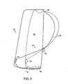
- FIG. 3 where backpack body 20 is shown in its non-compressed form in solid lines and in its compressed form in dashed lines.
- the load in the backpack exerts a downward force in the direction of arrow F, causing the portions of shoulder straps 42 between first end 44 and D-ring 52 to lengthen, and the portion between second end 46 and D-ring 52 to shorten as the lateral sides 26 of backpack body 20 are compressed.
- This compression happens automatically as a function of the construction of compression assembly 43 when the user lifts the backpack. Any adjustment of shoulder straps 42 by the user is for comfort only.
- Compression of the load in backpack body 20 advantageously moves the load closer to the user's lower back and hips, which is a more secure and appropriate place for the load to be supported than on the shoulders.
- slidably securing shoulder straps 42 along lateral sides 26 allows expansion of the backpack body for easy lading.
- shoulder straps 42 By configuring shoulder straps 42 such they extend along lateral sides 26 and bottom panel 24, automatic compression of backpack body 20 is accomplished with a continuous loop, while simultaneously providing additional support under bottom panel 24 by way of shoulder straps 42.
- the center of gravity of backpack body 20 is advantageously moved lower and closer to the user's hips and lower back, allowing the user to more comfortably and easily carry a load.
- first D-ring 52 is secured to backpack body 20 at a point higher than the point at which second D-ring 54 is secured to backpack body 20.
- Such a construction allows shoulder strap 42 to more easily slide through the D-rings as the load in the backpack is compressed.
- second D-ring 54 be secured close to the bottom of backpack body 20, although it should be realized that it could be attached up to several inches or more above the bottom of backpack body 20.
- D-rings 52 and 54 may be disposed at different angles, depending on their relative orientation with respect to one another and backpack body 20, in order to ensure that shoulder strap 42 can pass through the D-rings with the least amount of resistance.
- FIG. 4 Another preferred embodiment of compression assembly 43 is shown in FIG. 4 , in which shoulder strap 42 is slidably secured by way of first and second grommets 53, 55, which are secured to backpack body 20 proximate fifth junction 40 and third junction 34, respectively.
- grommet 53 is disposed in a hip portion 57 of backpack body that extends from fifth junction 40.
- An optional hip strap 59, having an adjustable buckle 61 is secured by stitching or other suitable means to hip portion 57.
- hip strap 59 may be formed of two separate portions.
- Grommet 55 is shown here secured to a flange member 63, which in turn is secured to third junction 34 by stitching or other suitable means.
- Grommets 53, 55 may be formed of plastic, metal or any other suitable material. Plastic grommets may be sewn or press-fit to backpack body 20, while metal grommets may be press-fit to backpack body 20.
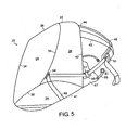
- FIG. 5 Another preferred embodiment of compression assembly 43 is shown in FIG. 5 , in which shoulder strap 42 is retained along lateral side 26 by a strap guide 49 and second D-ring 54.
- Strap guide 49 in the illustrated embodiment, is a piece of material secured to hip portion 57 by stitching or other suitable means. Strap guide 49 includes a pair of apertures 51 through which shoulder strap 42 passes. Strap guide 49 may be formed of the material that forms backpack body 20, leather, or any other suitable material.
- FIG. 6 Another preferred embodiment of compression assembly 43 is shown in FIG. 6 , in which a pocket 56 is positioned on at least one lateral side 26, with shoulder strap 42 passing through pocket 56.
- a first aperture 58 is located at one side of pocket 56, proximate fifth junction 40.
- a second aperture 60 is located at one side of pocket 56, proximate second junction 34.
- Shoulder strap 42 passes through first D-ring 52, through first aperture 58, through pocket 56, out through second aperture 60 and then through second D-ring 54.
- Shoulder strap 42 passes freely through pocket 56 and acts as described above to automatically compress backpack body 20 when the backpack is loaded and placed on a user's shoulders.
- shoulder strap 42 actually passes through pocket 56, and is positioned behind the fabric that forms pocket 56.
- pocket 56 is formed of a mesh material.
- a zipper 62 may be provided on pocket 56 to provide access to the contents of pocket 56.
- Pocket 56 may be formed of any suitable material, including, for example, the same material that forms the remainder of backpack body 20, as illustrated in FIG. 7.
- FIG. 7 also illustrates an alternative embodiment, in which there is no D-ring at fifth junction 40. Rather, shoulder strap 42 is retained by first aperture 58 formed in pocket 56.
- a second D-ring 54 is shown. However, it is to be appreciated that second D-ring 54 could also be eliminated, such that shoulder strap would be slidably secured to lateral side 26 by pocket 56 and first and second apertures 58, 60.
- compression assembly 43 is shown in FIG. 8 , in which a compression member 64 is positioned adjacent an outer surface of outer side 28 of backpack body 20.
- compression member 64 includes a ring 66 extending around a peripheral edge of outer side 28, and a retaining member 68.
- Ring may be, as illustrated here, a cylindrical metal rod formed of, for example, aluminum.
- Retaining member 68 may be, as illustrated here, a piece of fabric or other material stitched or otherwise secured to outer side 28, which maintains ring 66 adjacent outer side 28.
- a plurality of recesses 70 is formed around the periphery of retaining member 68, exposing ring 66 as it passes through each recess 70.
- Compression member 64 acts to disperse the compressive force across outer side 28 of backpack body 20, thereby more fully compressing the load in the backpack.
- compression assembly 43 is illustrated in FIG. 9 , in which compression member 68 comprises a compression plate 74 and a pair of retaining straps 76.
- Compression plate 74 is a substantially planar rectangular member that extends across outer side 28 of backpack body 20.
- Compression plate 74 may be formed of metal, plastic, or any other material suitable for compressing a load in backpack body 20.
- compression plate 74 is relatively narrow and covers only a lower portion of outer side 28. It is to be appreciated that compression plate may be larger than the embodiment illustrated here, and may cover a more substantial portion of outer side 28, and may even cover substantially all of outer side 28.
- Retaining straps 76 are connected at opposite ends thereof to compression plate 74 and a corresponding shoulder strap 42.
- Retaining straps 76 serve to maintain compression plate 74 in position adjacent outer side 28. As the user dons backpack body 20, the compressive force generated by shoulder straps 42 is transmitted to compression plate 74 by way of retaining straps 76, and the compressive force is distributed across outer side 28. It is to be appreciated that a single retaining strap could be used in accordance with the present invention, with opposite ends thereof secured to corresponding shoulder straps 42, and a central portion thereof secured to compression plate 74. In certain preferred embodiments, compression plate may be housed in a pocket or sleeve of backpack body 20, formed as part of backpack body 20, or stitched or otherwise secured to outer side 28.
- Compression member 64 may take many forms and/or shapes, such as rectangular, circular, etc., and may extend across a small portion or a majority of the surface of outer side 28.
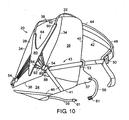
- compression member 64 takes the form of a substantially V-shaped member 80, as illustrated in FIG. 10 .
- Each of a plurality of retaining straps 82 is connected at a first end thereof to shoulder straps 42 and at a second end thereof to V-shaped member 80.
- three flanges 84 are formed on each of opposed sides of V-shaped member 80, with a pair of retaining straps 82 being secured to each flange 84.
- retaining straps 82 may be secured to shoulder straps 42 by way of an anchoring member, such as a disk 86, which is in turn connected to shoulder strap 42 by way of a connecting strap 88.
- Retaining straps 82 may be elastic cords, webbing, or any other suitable elongate member that can connect V-shaped member 80 to shoulder straps 42.
- Upper ends 90 of V-shaped member 80 may be secured to upper ends 44 of shoulder straps 42.
- load lift straps 92 extend from upper ends 90 of V-shaped member 80 to upper ends 44 of shoulder straps 42. Load lift straps 92 serve to maintain the upper portion of V-shaped member adjacent outer side 28, and also help to compress the load in backpack body 20.
Landscapes
- Portable Outdoor Equipment (AREA)
- Percussion Or Vibration Massage (AREA)
- Eye Examination Apparatus (AREA)
- Massaging Devices (AREA)
Abstract
Description
- This invention relates generally to backpacks, and, in particular, to backpacks having compression systems that compress the contents of the backpack and minimize stresses presented to the wearer.
- Backpacks for day use are well known, and their use has increased dramatically in recent years. Frameless backpacks rely on shoulder straps, and, optionally, hip straps, to carry the load. These backpacks are used for day hiking and other outdoor recreational activities, as well as by students for carrying books and supplies between school and home. Many students today need to carry more books and supplies than they have in the past due to the emphasis being placed on improving schools and the quality of education afforded young people, resulting in heavy loads being carried in the students' backpacks.
- Along with the heavier loads being carried more frequently by these frameless packs comes the increased potential for fatigue, discomfort, poor posture, and even musculoskeletal disorder and injury. This places a premium on backpack design to minimize such potential. However, the suspension systems in many such backpacks are simply incapable of providing an ergonomically correct fit. A backpack with standard shoulder straps primarily carries the load on the shoulders. However, the more a load can ride on the hips, the less load pressure there is on the shoulders. Further, the closer the load is to the back of the user, the more upright the user is able to walk, and, consequently, there is less pressure on the hip joints.
- If the load in the backpack is compressed, it has less tendency to shift around when the user is moving, jumping, or bending over. The more a load moves, the more the body has to work and move to compensate for the load shifting. The more the body has to move and work to compensate, the greater the chance for injury or body stress. Thus it would be desirable to provide a backpack that moves the load closer to the back and in the direction of the lower back and hips, and also helps to stabilize the load in the backpack.
-
U.S. Patent No. 6,164,509 to Gausling et al . discloses a backpack with a shoulder strap secured at one end to a top edge of a body side panel of the backpack. The strap extends across a lower portion of a lateral side of the backpack, and is secured to the backpack at a junction between the lateral side and an outer side of the backpack. Another strap is connected at its first end to the shoulder strap, extends beneath the backpack body, and is connected at its other end to a junction between the bottom of the backpack body and the outer side of the backpack body. The weight of the contents of the backpack act to compress the outer side of the backpack body toward the body when the back is placed on a user's shoulders, thereby shifting the weight closer to the user's back. Gausling is limiting in that it has a complicated construction requiring excessive straps, and, therefore, one that has increased manufacturing costs and potential for functional and maintenance problems. - It is an object of the present invention to provide an improved backpack that reduces or overcomes some or all of the difficulties inherent in prior known devices. Particular objects and advantages of the invention will be apparent to those skilled in the art, that is, those who are knowledgeable or experienced in this field of technology, in view of the following disclosure of the invention and detailed description of certain preferred embodiments.
- The present invention is directed to a backpack with a compression system that is efficient and effective in minimizing the stresses presented to a wearer using a loaded backpack, and, therefore, allows the wearer to carry heavier loads for a longer period of time with reduced fatigue and discomfort.
- In accordance with a first aspect, a backpack with a compression system includes a backpack body having a top side, a bottom side, two lateral sides, a body side, an outer side, and a pair of shoulder straps. Each shoulder strap has a first end connected at a junction of the top side and the body side, and a second end connected to the backpack body at a junction of the bottom side and the body side. The straps extend along a corresponding lateral side and the bottom of the backpack body, and are slidably connected to the backpack body at a junction of the body side and a corresponding lateral side, and at a junction of the corresponding lateral side and the outer side.
- In accordance with another aspect, a backpack with a compression system includes a backpack body having a top side, a bottom side, two lateral sides, a body side, an outer side, and a compression assembly. The compression assembly includes a pair of shoulder straps and a compression member. Each shoulder strap has a first end connected at a junction of the top side and the body side, and a second end connected to the backpack body at a junction of the bottom side and the body side. The straps extend along a corresponding lateral side and the bottom of the backpack body, and are slidably connected to the backpack body at a junction of the body side and a corresponding lateral side, and at a junction of the corresponding lateral side and the outer side. The compression member is positioned adjacent an outer surface of the outer side and is secured to each of the shoulder straps.
- In accordance with another aspect, a backpack with a compression system includes a backpack body having a top side, a bottom side, two lateral sides, a body side and an outer side, and a pair of shoulder straps. Each shoulder strap has a first end connected at a junction of the top side and the body side, and a second end connected to the backpack body at a junction of the bottom side and the body side. Each shoulder strap extends along a corresponding lateral side and the bottom of the backpack body, and is slidably connected to the backpack body at a junction of the body side and a corresponding lateral side, and at a junction of the corresponding lateral side and the outer side such that the lateral sides will automatically compress and a portion of each shoulder strap between the first end and the junction of the body side and the corresponding lateral side will lengthen when the loaded backpack is lifted.
- Substantial advantage is achieved by providing a backpack with a compression system as described herein. In particular, a backpack with a compression system automatically compresses the load in the pack, shifting the load closer to the wearer's lower back and hips. Thus, such a backpack maximizes wearer comfort and health, even when the pack is fully loaded.
- These and additional features and advantages of the invention disclosed here will be further understood from the following detailed disclosure of certain preferred embodiments.
-
-
FIG. 1 is a perspective view of a backpack of the prior art. -
FIG. 2 is a perspective view of a preferred embodiment of a backpack with a compression assembly in accordance with the present invention. -
FIG. 3 is a schematic illustration of the automatic compression feature of the compression assembly ofFIG. 2 . -
FIG. 4 is a perspective view of the backpack ofFIG. 2 , with an alternative embodiment of a compression assembly in accordance with the present invention. -
FIG. 5 is a perspective view of the backpack ofFIG. 2 , with another alternative embodiment of a compression assembly in accordance with the present invention. -
FIG. 6 is a perspective view of the backpack ofFIG. 2 , with yet another alternative embodiment of a compression assembly in accordance with the present invention. -
FIG. 7 is a perspective view of the backpack ofFIG. 2 , with another alternative embodiment of a compression assembly in accordance with the present invention. -
FIG. 8 is a perspective view of the backpack ofFIG. 2 , with another alternative embodiment of a compression assembly having a compression member in accordance with the present invention. -
FIG. 9 is a perspective view of the backpack ofFIG. 2 , with another embodiment of a compression member of the compression assembly in accordance with the present invention. -
FIG. 10 is a perspective view of the backpack ofFIG. 2 , with yet another embodiment of a compression member of the compression assembly in accordance with the present invention. - The figures referred to above are not drawn necessarily to scale and should be understood to present a representation of the invention, illustrative of the principles involved. Some features of the backpack with a compression system depicted in the drawings have been enlarged or distorted relative to others to facilitate explanation and understanding. The same reference numbers are used in the drawings for similar or identical components and features shown in various alternative embodiments. Backpacks with compression systems as disclosed herein, would have configurations and components determined, in part, by the intended application and environment in which they are used.
- A
typical backpack body 20 of the prior art is shown inFIG. 1 , and is formed by a number of panels or sides. The reference numbers used for many of the elements ofbackpack body 20 are used for similar or identical components of preferred embodiments of the present invention described below. -
Backpack body 20 has a top side orregion 22, a bottom side orregion 24, two lateral sides orregions 26, an outer side orregion 28, and a body side orregion 30. Separating the various panels or side regions is a series of junctions or seams. When connected, these six panel regions define an interior compartment inbackpack body 20 into which cargo such as books, food, clothing, etc. may be stowed. Of course; this interior compartment may be subdivided into, or complemented with, a number of additional compartments or regions for keeping various items separate. This allows a user to more efficiently pack and organize the backpack, which can provide for better access to important items, as well as distribute the load properly in the backpack. Although such a six-panel configuration is not necessary, it is helpful in helping to describe the features and advantages of the present invention. - Although six particular sides or panels are described,
backpack body 20 can comprise fewer panels or sides, and have correspondingly fewer seams or junctions, and be within the scope of the invention. For instance, the body, top, bottom, outer, and lateral sides could be formed of one continuous piece of fabric with no actual seams or junctions, and such a construction is to be considered within the scope of the present invention. In such a case,backpack body 20 could still be described as having a number of seams or junctions, which would aid in understanding the relative location onbackpack body 20 being discussed. Alternatively,backpack body 20 could have more than six panels or sides and corresponding seams or junctions, and such a configuration is also considered to be within the scope of the invention. - A
first junction 32 is defined betweentop panel 22 andbody side 30.Second junctions 34 are similarly disposed in the regions between theouter side 28 and the twolateral sides 26. Athird junction 36 defines a transition region between thebottom panel 24 and theouter side 28, and afourth junction 38 is disposed generally between theouter side 28 and the top panel orside 22.Fifth junctions 40 are disposed betweenlateral sides 26 andbody side 30.Sixth junctions 41 are disposed betweenbody side 30 andbottom panel 24. - These various seams or junctions described herein are meant to define a region as opposed to a specific location on
body 20. Thus,first junction 32 betweentop side 22 andbody side 30 is meant only to define a general region of transition between these twosides first junction 32 into the region of thetop side 22 orbody side 30, or anywhere along the line shown in the figures as defining these junctions, and still be within the scope of the term junction. Consequently when corresponding elements of the backpack are described as being connected to, or disposed at, a junction, it is to be appreciated that the point of connection or disposal is in a region at or near the particular junction, and need not be exactly connected to or disposed at that junction. - Thus, junctions can comprise a general transition region from one section of
backpack body 20 to another without any discontinuity in the panel or side. For instance, a junction can generally define a region where the panels or sides transition from one orientation to another, particularly whenbackpack body 20 is loaded with contents. Thus, a junction can be merely a bend inbackpack body 20. - Alternatively, the junctions can be a distinct part of
backpack body 20, such as a seam formed by sewing, or any other type of permanent bonding or fusing of the two sides. Further, a junction can be a temporary seam along or near which a body compartment can be opened and closed. In the latter case, a junction can represent an area near a nylon or metal zipper, a hook and loop-type fastener, snaps, buttons, and the like. - The discussion and designation of the various components of a preferred embodiment of a
backpack body 20 shown inFIG. 2 , including the panels or sides and their corresponding seams as described below, are simplified so that the advantages of the present invention can be particularly described. For instance, it is within the scope of the invention that althoughbackpack body 20 defines a compartment into which cargo such as books, clothing, food, etc. may be placed, additional compartments and features such as outer and side compartments, loops, etc. may be added tobackpack body 20. - In the backpack body of
FIG. 1 , a pair ofshoulder straps 42 are secured at first ends 44 thereof tobackpack body 20 proximate first junction 32 (hidden from view here) by stitching or other suitable means. Asecond end 46 of eachshoulder strap 42 is secured by stitching or other suitable means tofifth junction 40 proximate a lower end ofbackpack body 20.Shoulder straps 42 serve to support the weight of the backpack on the shoulders of the user in known fashion. - The panels making up
backpack body 20, as well as the straps and other components of the invention can variously comprise a number of natural or synthetic materials. Natural fabric such as leather, cotton and the like may be useful for certain applications. Preferred are synthetic fabrics made from thermoplastic materials such as polypropylene, polyvinyl chloride, polyamide (such as nylon), polyethylene, polyester, etc. Especially preferred is nylon that can be textured for breathability, wear-resistance, and waterproofed with materials such as silicone elastomers and the like. Particularly useful is a type of nylon known as Cordura (supplied by E.I. du Pont de Nemours & Co. of Wilmington, Del.). Multiple or composite layer configurations as are well-known in the art, in which a tougher, more durable weave comprises an outer layer, while a lighter, thinner, and more flexible inner weave comprises an inner layer. Some of these materials known in the industry, such as Gore-Tex (supplied by W.L. Gore & Associates of Newark, Del.), Tri-Shield (supplied by Tri-Seal International of Blauvelt, N.Y.), Spandura (provided by H. Warsaw & Sons of New York, N.Y.), etc. can be used as appropriate. - As seen in a preferred embodiment of the present invention shown in
FIG. 2 ,shoulder straps 42 may be provided withpadding 48 to improve the comfort and fit for the user. Shoulder straps 42 may also be provided with anadjustable buckle 50. In the illustrated embodiment, the configuration ofbuckle 50 requiresshoulder strap 42 to be formed of two pieces. It is to be appreciated that a shoulder strap, or any other strap described herein, such as a hip strap, formed of more than one piece is considered to be, along with any associated buckle or other adjustable fastener, an integral strap within the scope of the present invention. -
Shoulder strap 42 is connected at itsfirst end 44 tobackpack body 20 proximatefirst junction 32.Second end 46 ofshoulder strap 42 is connected tobackpack body 20 proximatesixth junction 41. Betweenfirst end 44 andsecond end 46,shoulder strap 42 extends alonglateral side 26 ofbackpack body 20 fromfifth junction 40 across tosecond junction 34, and back acrossbottom panel 24 tosixth junction 41. In a preferred embodiment,shoulder strap 42 is slidably connected tobackpack body 20 atfifth junction 40 andsecond junction 34. In a preferred embodiment, the location at whichshoulder strap 42 is slidably connected atfifth junction 40 is at a higher position than the location at whichshoulder strap 42 is slidably connected atsecond junction 34. - In the embodiment illustrated in
FIG. 2 ,shoulder strap 42 is slidably connected tobackpack body 20 by way of a first D-ring 52 secured tobackpack body 20 atfifth junction 40. Similarly,shoulder strap 42 is slidably connected tobackpack body 20 by way of a second D-ring 54 secured tobackpack body 20 atsecond junction 34. D-rings 52, 54 maintainshoulder straps 42 close tolateral sides 26 and provide for load compression ofbackpack body 20. It is to be appreciated that elements other than D-rings can be provided to allow for sliding movement ofshoulder straps 42 alonglateral sides 26 such as sleeves or grommets, as discussed below, or any other suitable structure that will allow for sliding movement of the straps. - When the user places the shoulder straps over their shoulders, the load in the backpack is automatically compressed due to the weight of the load, and the fact that shoulder straps 42 are slidably secured to
backpack body 20. This is schematically illustrated inFIG. 3 , wherebackpack body 20 is shown in its non-compressed form in solid lines and in its compressed form in dashed lines. When a loaded backpack is picked up, the load in the backpack exerts a downward force in the direction of arrow F, causing the portions ofshoulder straps 42 betweenfirst end 44 and D-ring 52 to lengthen, and the portion betweensecond end 46 and D-ring 52 to shorten as the lateral sides 26 ofbackpack body 20 are compressed. This compression happens automatically as a function of the construction ofcompression assembly 43 when the user lifts the backpack. Any adjustment ofshoulder straps 42 by the user is for comfort only. - Compression of the load in
backpack body 20 advantageously moves the load closer to the user's lower back and hips, which is a more secure and appropriate place for the load to be supported than on the shoulders. Similarly, slidably securingshoulder straps 42 alonglateral sides 26 allows expansion of the backpack body for easy lading. - By configuring
shoulder straps 42 such they extend alonglateral sides 26 andbottom panel 24, automatic compression ofbackpack body 20 is accomplished with a continuous loop, while simultaneously providing additional support underbottom panel 24 by way of shoulder straps 42. The center of gravity ofbackpack body 20 is advantageously moved lower and closer to the user's hips and lower back, allowing the user to more comfortably and easily carry a load. - In a preferred embodiment, first D-
ring 52 is secured tobackpack body 20 at a point higher than the point at which second D-ring 54 is secured tobackpack body 20. Such a construction allowsshoulder strap 42 to more easily slide through the D-rings as the load in the backpack is compressed. As illustrated here, it is preferred that second D-ring 54 be secured close to the bottom ofbackpack body 20, although it should be realized that it could be attached up to several inches or more above the bottom ofbackpack body 20. D-rings 52 and 54 may be disposed at different angles, depending on their relative orientation with respect to one another andbackpack body 20, in order to ensure thatshoulder strap 42 can pass through the D-rings with the least amount of resistance. - Another preferred embodiment of
compression assembly 43 is shown inFIG. 4 , in whichshoulder strap 42 is slidably secured by way of first andsecond grommets backpack body 20 proximatefifth junction 40 andthird junction 34, respectively. In the embodiment shown here,grommet 53 is disposed in ahip portion 57 of backpack body that extends fromfifth junction 40. Anoptional hip strap 59, having anadjustable buckle 61 is secured by stitching or other suitable means tohip portion 57. As noted above and illustrated here,hip strap 59 may be formed of two separate portions.Grommet 55 is shown here secured to aflange member 63, which in turn is secured tothird junction 34 by stitching or other suitable means.Grommets backpack body 20, while metal grommets may be press-fit tobackpack body 20. - Another preferred embodiment of
compression assembly 43 is shown inFIG. 5 , in whichshoulder strap 42 is retained alonglateral side 26 by astrap guide 49 and second D-ring 54.Strap guide 49, in the illustrated embodiment, is a piece of material secured tohip portion 57 by stitching or other suitable means.Strap guide 49 includes a pair ofapertures 51 through whichshoulder strap 42 passes.Strap guide 49 may be formed of the material that formsbackpack body 20, leather, or any other suitable material. - Another preferred embodiment of
compression assembly 43 is shown inFIG. 6 , in which apocket 56 is positioned on at least onelateral side 26, withshoulder strap 42 passing throughpocket 56. Afirst aperture 58 is located at one side ofpocket 56, proximatefifth junction 40. Asecond aperture 60 is located at one side ofpocket 56, proximatesecond junction 34.Shoulder strap 42 passes through first D-ring 52, throughfirst aperture 58, throughpocket 56, out throughsecond aperture 60 and then through second D-ring 54.Shoulder strap 42 passes freely throughpocket 56 and acts as described above to automatically compressbackpack body 20 when the backpack is loaded and placed on a user's shoulders. As illustrated here,shoulder strap 42 actually passes throughpocket 56, and is positioned behind the fabric that formspocket 56. It is to be appreciated that a sleeve could be incorporated withinpocket 56, within whichshoulder strap 42 could pass, thereby keepingshoulder strap 42 from getting encumbered by the contents ofpocket 56. In this embodiment,pocket 56 is formed of a mesh material. Azipper 62 may be provided onpocket 56 to provide access to the contents ofpocket 56. -
Pocket 56 may be formed of any suitable material, including, for example, the same material that forms the remainder ofbackpack body 20, as illustrated inFIG. 7. FIG. 7 also illustrates an alternative embodiment, in which there is no D-ring atfifth junction 40. Rather,shoulder strap 42 is retained byfirst aperture 58 formed inpocket 56. In the embodiment illustrated here, a second D-ring 54 is shown. However, it is to be appreciated that second D-ring 54 could also be eliminated, such that shoulder strap would be slidably secured tolateral side 26 bypocket 56 and first andsecond apertures - Another preferred embodiment of
compression assembly 43 is shown inFIG. 8 , in which acompression member 64 is positioned adjacent an outer surface ofouter side 28 ofbackpack body 20. In the embodiment illustrated inFIG. 8 ,compression member 64 includes aring 66 extending around a peripheral edge ofouter side 28, and a retainingmember 68. Ring may be, as illustrated here, a cylindrical metal rod formed of, for example, aluminum. Retainingmember 68 may be, as illustrated here, a piece of fabric or other material stitched or otherwise secured toouter side 28, which maintainsring 66 adjacentouter side 28. In a preferred embodiment, a plurality ofrecesses 70 is formed around the periphery of retainingmember 68, exposingring 66 as it passes through eachrecess 70.Shoulder strap 42 extends through first D-ring 52, extends acrosslateral side 26, slidably wraps about an exposed length ofring 66, and extends back acrossbottom panel 24 tosixth junction 41.Compression member 64 acts to disperse the compressive force acrossouter side 28 ofbackpack body 20, thereby more fully compressing the load in the backpack. - Another embodiment of
compression assembly 43 is illustrated inFIG. 9 , in whichcompression member 68 comprises acompression plate 74 and a pair of retaining straps 76.Compression plate 74 is a substantially planar rectangular member that extends acrossouter side 28 ofbackpack body 20.Compression plate 74 may be formed of metal, plastic, or any other material suitable for compressing a load inbackpack body 20. In the illustrated embodiment,compression plate 74 is relatively narrow and covers only a lower portion ofouter side 28. It is to be appreciated that compression plate may be larger than the embodiment illustrated here, and may cover a more substantial portion ofouter side 28, and may even cover substantially all ofouter side 28. Retainingstraps 76 are connected at opposite ends thereof tocompression plate 74 and acorresponding shoulder strap 42. Retainingstraps 76 serve to maintaincompression plate 74 in position adjacentouter side 28. As the user donsbackpack body 20, the compressive force generated byshoulder straps 42 is transmitted tocompression plate 74 by way of retainingstraps 76, and the compressive force is distributed acrossouter side 28. It is to be appreciated that a single retaining strap could be used in accordance with the present invention, with opposite ends thereof secured to correspondingshoulder straps 42, and a central portion thereof secured tocompression plate 74. In certain preferred embodiments, compression plate may be housed in a pocket or sleeve ofbackpack body 20, formed as part ofbackpack body 20, or stitched or otherwise secured toouter side 28. -
Compression member 64 may take many forms and/or shapes, such as rectangular, circular, etc., and may extend across a small portion or a majority of the surface ofouter side 28. In one preferred embodiment,compression member 64 takes the form of a substantially V-shapedmember 80, as illustrated inFIG. 10 . Each of a plurality of retainingstraps 82 is connected at a first end thereof toshoulder straps 42 and at a second end thereof to V-shapedmember 80. In a preferred embodiment, three flanges 84 are formed on each of opposed sides of V-shapedmember 80, with a pair of retainingstraps 82 being secured to each flange 84. The first ends of retainingstraps 82 may be secured toshoulder straps 42 by way of an anchoring member, such as adisk 86, which is in turn connected toshoulder strap 42 by way of a connectingstrap 88. Retainingstraps 82 may be elastic cords, webbing, or any other suitable elongate member that can connect V-shapedmember 80 to shoulder straps 42. - Upper ends 90 of V-shaped
member 80 may be secured to upper ends 44 of shoulder straps 42. In a preferred embodiment, load lift straps 92 extend from upper ends 90 of V-shapedmember 80 to upper ends 44 of shoulder straps 42. Load lift straps 92 serve to maintain the upper portion of V-shaped member adjacentouter side 28, and also help to compress the load inbackpack body 20. - In light of the foregoing disclosure of the invention and description of the preferred embodiments, those skilled in this area of technology will readily understand that various modifications and adaptations can be made without departing from the scope of the invention as defined by the following claims.
Claims (23)
- A backpack with a compression system comprising, in combination:a backpack body (20) having a top side (22), a bottom side (24), two lateral sides (26), a body side (30) and an outer side (28);a pair of shoulder straps (42), characterized in that, each shoulder strap has a first end (44) connected at a junction (32) of the top side and the body side, and a second end (46) connected to the backpack body at a junction (41) of the bottom side and the body side, the strap (42) extends along a corresponding lateral side (26) and the bottom (24) of the backpack body, and is slidably connected to the backpack body (20) at a junction (40) of the body side and a corresponding lateral side, and at a junction (34) of the corresponding lateral side and the outer side.
- The backpack of claim 1, further comprising
a compression assembly (43) comprising the shoulder straps and
a compression member (64) positioned adjacent an outer surface of the outer side and secured to each of the shoulder straps. - The backpack of claim 1 or claim 2, wherein the shoulder straps are slidably connected to the backpack body by way of a D-ring (52, 54).
- The backpack of claim 1 or claim 2, wherein the shoulder straps are slidably connected to the backpack body by way of a grommet (53, 55).
- The backpack of claim 1 or claim 2, wherein the shoulder straps are slidably connected to the backpack body by way of a strap guide (49).
- The backpack of claim 1 or claim 2, further comprising hip portions (57) secured to the junctions between corresponding lateral sides and the body side.
- The backpack of claim 6, wherein the shoulder straps are slidably connected to the backpack body by way of a grommet (53) secured to a corresponding hip portion.
- The backpack of claim 1 further comprising hip portions (57) secured to the junctions between corresponding lateral sides and the body side, wherein the shoulder straps are slidably connected to the backpack body by way of a strap guide (49) secured to a corresponding hip portion.
- The backpack of claim 6, further comprising a hip strap (59) connected at opposite ends thereof to the hip portions.
- The backpack of claim 1, further comprising a pocket (56) formed on at least one lateral side of the backpack body, with a corresponding shoulder strap passing through the pocket.
- The backpack of claim 10, wherein an aperture (58, 60) is formed on each side of the pocket, the shoulder strap passing through each of the apertures.
- The backpack of claim 10, wherein the pocket is formed of webbing.
- The backpack of claim 1, further comprising a compression member (64) positioned adjacent the outer side of the backpack body and connected to the shoulder straps.
- The backpack of claim 2 or claim 13, wherein the compression member is a substantially planar member (74) that extends along a lower portion of the outer side of the backpack body.
- The backpack of claim 2 or claim 13, wherein the compression member comprises a ring (66), the shoulder straps passing through the ring.
- The backpack of claim 15, wherein the compression member comprises a retaining member (68) secured to the outer side of the backpack body, the ring positioned between the retaining member and the outer side of the backpack body.
- The backpack of claim 16, wherein the retaining member comprises a piece of fabric sewn to the outer side of the backpack body.
- The backpack of claim 2 or claim 13, wherein the compression member comprises a substantially V-shaped member (80).
- The backpack of claim 18, wherein upper ends (90) of the substantially V-shaped member are connected to upper ends (44) of corresponding shoulder straps.
- The backpack of claim 18, wherein each upper end of the substantially V-shaped member is connected to an upper end of a corresponding shoulder strap by a load lift strap (92).
- The backpack of claim 1, wherein each shoulder strap is slidably connected to the junction of the body side and a corresponding lateral side at a higher position than the location at which the shoulder strap is slidably connected to the junction of the corresponding lateral side and the outer side.
- The backpack of claim 1, wherein the shoulder straps are configured such that the backpack body is automatically compressed upon lifting of the backpack body when the backpack body is loaded.
- The backpack of claim 1, wherein the shoulder straps are configured such that the lateral sides will automatically compress and as portion of each shoulder strap between the first end and the junction of the body side and the corresponding lateral side will lengthen when a loaded backpack is lifted.
Applications Claiming Priority (2)
| Application Number | Priority Date | Filing Date | Title |
|---|---|---|---|
| US10/702,223 US7204399B2 (en) | 2003-11-05 | 2003-11-05 | Compression system for backpack |
| PCT/US2004/032778 WO2005046387A1 (en) | 2003-11-05 | 2004-11-03 | Compression system for backpack |
Publications (2)
| Publication Number | Publication Date |
|---|---|
| EP1684611A1 EP1684611A1 (en) | 2006-08-02 |
| EP1684611B1 true EP1684611B1 (en) | 2008-12-31 |
Family
ID=34551618
Family Applications (1)
| Application Number | Title | Priority Date | Filing Date |
|---|---|---|---|
| EP04800470A Expired - Lifetime EP1684611B1 (en) | 2003-11-05 | 2004-11-03 | Compression system for backpack |
Country Status (5)
| Country | Link |
|---|---|
| US (1) | US7204399B2 (en) |
| EP (1) | EP1684611B1 (en) |
| AT (1) | ATE418889T1 (en) |
| DE (1) | DE602004018820D1 (en) |
| WO (1) | WO2005046387A1 (en) |
Families Citing this family (22)
| Publication number | Priority date | Publication date | Assignee | Title |
|---|---|---|---|---|
| US20060113346A1 (en) * | 2004-11-30 | 2006-06-01 | Bridgestone Sports Co., Ltd. | Caddie bag |
| US20060137950A1 (en) * | 2004-12-23 | 2006-06-29 | Nike, Inc. | Compression system for a bag |
| US7896207B1 (en) * | 2006-03-20 | 2011-03-01 | Michael Latham | Wedge-shaped storage bag for attachment to a bicycle frame and car carrier |
| US8181835B2 (en) * | 2007-01-25 | 2012-05-22 | Penguin Brands, Inc. | Resilient strap mounting for user-borne athletic packs |
| US9439501B2 (en) | 2009-04-24 | 2016-09-13 | Joan F. Demskey | Backpack |
| US9167883B2 (en) | 2009-04-24 | 2015-10-27 | Joan F. Demskey | Backpack |
| US8281970B2 (en) * | 2009-04-24 | 2012-10-09 | Demskey Joan F | Backpack having a load compensating strap arrangement |
| US8657169B2 (en) | 2009-04-24 | 2014-02-25 | Joan F. Demskey | Backpack |
| US8998051B2 (en) | 2009-04-24 | 2015-04-07 | Joan F. Demskey | Backpack |
| FR2956798B1 (en) * | 2010-02-26 | 2012-04-27 | Decathlon Sa | BACKPACK WITH RAPID ADJUSTMENT OF STRAPS |
| US8668127B2 (en) | 2011-02-28 | 2014-03-11 | Jake Ryan Baron | Stretchable backpack |
| KR200469441Y1 (en) | 2011-12-02 | 2013-10-17 | 이정모 | Suspenders structure of bagpack |
| WO2014005132A1 (en) | 2012-06-29 | 2014-01-03 | Pei Li | Compression system for backpack |
| USD725378S1 (en) | 2014-05-30 | 2015-03-31 | Nike, Inc. | Backpack |
| US9730499B2 (en) * | 2015-01-16 | 2017-08-15 | Nike, Inc. | Convertible carrying bag |
| US10165846B1 (en) * | 2017-06-16 | 2019-01-01 | Camelbak Products, Llc | Backpacks with cooperatively adjusted hip belts and compression straps |
| US10251466B2 (en) * | 2017-07-17 | 2019-04-09 | Nancy Soltez | Backpack with auxiliary handholds |
| US20220047052A1 (en) * | 2020-08-12 | 2022-02-17 | Scott Graham Haack | Removable Luggage Storage Accessory |
| US12150533B2 (en) * | 2020-09-16 | 2024-11-26 | John J. Waswill | Sports bag |
| CA3141175A1 (en) * | 2021-12-06 | 2023-06-06 | Graham M. Armitage | Backpack with shoulder straps crossing and non-fixed at top to support load from base |
| USD1027427S1 (en) * | 2022-02-02 | 2024-05-21 | Dell Products L.P. | Backpack |
| USD1023554S1 (en) * | 2022-02-02 | 2024-04-23 | Dell Products L.P. | Backpack |
Family Cites Families (11)
| Publication number | Priority date | Publication date | Assignee | Title |
|---|---|---|---|---|
| US1397161A (en) * | 1920-03-12 | 1921-11-15 | Clemetson Tobias | Pack-sack |
| US1696191A (en) * | 1928-03-01 | 1928-12-25 | Coulson Hugh Geoffrey | Pack |
| US2262313A (en) * | 1940-04-26 | 1941-11-11 | Frank P Clappier | Knapsack or pack carrying harness |
| FR2677235B1 (en) | 1991-06-06 | 1993-09-03 | Decathlon Production | DEVICE FOR ADJUSTING THE POSITIONING OF BACKPACKS. |
| US5431317A (en) * | 1994-02-24 | 1995-07-11 | Kliot; Eugene | Multimode traveling bag |
| IES71158B2 (en) | 1996-05-10 | 1997-01-29 | Lowe Alpine Holdings Limited | A rucksack |
| US6286461B1 (en) * | 1997-09-08 | 2001-09-11 | Gayle Martz, Inc. | Pet carrier with convertible straps |
| GB2343618A (en) | 1998-11-14 | 2000-05-17 | David Foster | Bag |
| US6179187B1 (en) | 1999-07-07 | 2001-01-30 | Mark L. Lemire | Ergonomically enhanced backpack |
| US6164509A (en) | 1999-07-19 | 2000-12-26 | Zero G Technologies, Llc | Ergonomic bookpack |
| US6488188B2 (en) * | 2001-04-02 | 2002-12-03 | Jack A. Fleischli | Combination backpack and protective body heat retaining pod |
-
2003
- 2003-11-05 US US10/702,223 patent/US7204399B2/en not_active Expired - Lifetime
-
2004
- 2004-11-03 DE DE602004018820T patent/DE602004018820D1/en not_active Expired - Lifetime
- 2004-11-03 EP EP04800470A patent/EP1684611B1/en not_active Expired - Lifetime
- 2004-11-03 WO PCT/US2004/032778 patent/WO2005046387A1/en not_active Ceased
- 2004-11-03 AT AT04800470T patent/ATE418889T1/en not_active IP Right Cessation
Also Published As
| Publication number | Publication date |
|---|---|
| US7204399B2 (en) | 2007-04-17 |
| WO2005046387A1 (en) | 2005-05-26 |
| EP1684611A1 (en) | 2006-08-02 |
| US20050092803A1 (en) | 2005-05-05 |
| ATE418889T1 (en) | 2009-01-15 |
| DE602004018820D1 (en) | 2009-02-12 |
Similar Documents
| Publication | Publication Date | Title |
|---|---|---|
| US7204399B2 (en) | Compression system for backpack | |
| KR100455511B1 (en) | Ergonomic bookpack | |
| US10076177B2 (en) | Compression system for backpack | |
| US6397392B1 (en) | Pocketed combination vest backpack | |
| US4029243A (en) | Integrated belt-supported backpack | |
| US4949401A (en) | Collapsible multicompartmented pack for the back of a garment | |
| AU609223B2 (en) | Belt | |
| US7431184B2 (en) | Backpack having distributed-load shoulder strap system | |
| US20060289585A1 (en) | Tool belt carrier, and pouch constructions | |
| US9826817B2 (en) | Convertible, self adjusting, multimodal strap system for carrying bags and packs | |
| US7870982B2 (en) | Utility shoulder belt | |
| US9113696B2 (en) | Backpack shoulder strap | |
| KR102711258B1 (en) | Convertible shoulder bags and backpacks | |
| US20120187172A1 (en) | Rucksacks | |
| US12102217B1 (en) | Convertible tote | |
| US20250375020A1 (en) | Bag assembly concealing one or more straps | |
| US20250185791A1 (en) | Interlocking suspension system for independent backpack and strap adjustment | |
| JP3249289U (en) | Backpack-type storage device | |
| US20260060406A1 (en) | Bag including an adjustment system | |
| HK1069962A (en) | Ergonomic backpack | |
| AU684732B2 (en) | A convertible backpack |
Legal Events
| Date | Code | Title | Description |
|---|---|---|---|
| PUAI | Public reference made under article 153(3) epc to a published international application that has entered the european phase |
Free format text: ORIGINAL CODE: 0009012 |
|
| 17P | Request for examination filed |
Effective date: 20060418 |
|
| AK | Designated contracting states |
Kind code of ref document: A1 Designated state(s): AT BE BG CH CY CZ DE DK EE ES FI FR GB GR HU IE IS IT LI LU MC NL PL PT RO SE SI SK TR |
|
| DAX | Request for extension of the european patent (deleted) | ||
| GRAP | Despatch of communication of intention to grant a patent |
Free format text: ORIGINAL CODE: EPIDOSNIGR1 |
|
| GRAS | Grant fee paid |
Free format text: ORIGINAL CODE: EPIDOSNIGR3 |
|
| GRAA | (expected) grant |
Free format text: ORIGINAL CODE: 0009210 |
|
| AK | Designated contracting states |
Kind code of ref document: B1 Designated state(s): AT BE BG CH CY CZ DE DK EE ES FI FR GB GR HU IE IS IT LI LU MC NL PL PT RO SE SI SK TR |
|
| REG | Reference to a national code |
Ref country code: GB Ref legal event code: FG4D Ref country code: CH Ref legal event code: EP |
|
| REF | Corresponds to: |
Ref document number: 602004018820 Country of ref document: DE Date of ref document: 20090212 Kind code of ref document: P |
|
| REG | Reference to a national code |
Ref country code: DE Ref legal event code: R096 Ref document number: 602004018820 Country of ref document: DE Effective date: 20090212 |
|
| REG | Reference to a national code |
Ref country code: IE Ref legal event code: FG4D |
|
| PG25 | Lapsed in a contracting state [announced via postgrant information from national office to epo] |
Ref country code: SI Free format text: LAPSE BECAUSE OF FAILURE TO SUBMIT A TRANSLATION OF THE DESCRIPTION OR TO PAY THE FEE WITHIN THE PRESCRIBED TIME-LIMIT Effective date: 20081231 Ref country code: PL Free format text: LAPSE BECAUSE OF FAILURE TO SUBMIT A TRANSLATION OF THE DESCRIPTION OR TO PAY THE FEE WITHIN THE PRESCRIBED TIME-LIMIT Effective date: 20081231 Ref country code: FI Free format text: LAPSE BECAUSE OF FAILURE TO SUBMIT A TRANSLATION OF THE DESCRIPTION OR TO PAY THE FEE WITHIN THE PRESCRIBED TIME-LIMIT Effective date: 20081231 Ref country code: NL Free format text: LAPSE BECAUSE OF FAILURE TO SUBMIT A TRANSLATION OF THE DESCRIPTION OR TO PAY THE FEE WITHIN THE PRESCRIBED TIME-LIMIT Effective date: 20081231 |
|
| NLV1 | Nl: lapsed or annulled due to failure to fulfill the requirements of art. 29p and 29m of the patents act | ||
| PG25 | Lapsed in a contracting state [announced via postgrant information from national office to epo] |
Ref country code: RO Free format text: LAPSE BECAUSE OF FAILURE TO SUBMIT A TRANSLATION OF THE DESCRIPTION OR TO PAY THE FEE WITHIN THE PRESCRIBED TIME-LIMIT Effective date: 20081231 Ref country code: ES Free format text: LAPSE BECAUSE OF FAILURE TO SUBMIT A TRANSLATION OF THE DESCRIPTION OR TO PAY THE FEE WITHIN THE PRESCRIBED TIME-LIMIT Effective date: 20090411 Ref country code: BE Free format text: LAPSE BECAUSE OF FAILURE TO SUBMIT A TRANSLATION OF THE DESCRIPTION OR TO PAY THE FEE WITHIN THE PRESCRIBED TIME-LIMIT Effective date: 20081231 Ref country code: EE Free format text: LAPSE BECAUSE OF FAILURE TO SUBMIT A TRANSLATION OF THE DESCRIPTION OR TO PAY THE FEE WITHIN THE PRESCRIBED TIME-LIMIT Effective date: 20081231 |
|
| PG25 | Lapsed in a contracting state [announced via postgrant information from national office to epo] |
Ref country code: SE Free format text: LAPSE BECAUSE OF FAILURE TO SUBMIT A TRANSLATION OF THE DESCRIPTION OR TO PAY THE FEE WITHIN THE PRESCRIBED TIME-LIMIT Effective date: 20090331 Ref country code: CZ Free format text: LAPSE BECAUSE OF FAILURE TO SUBMIT A TRANSLATION OF THE DESCRIPTION OR TO PAY THE FEE WITHIN THE PRESCRIBED TIME-LIMIT Effective date: 20081231 Ref country code: IS Free format text: LAPSE BECAUSE OF FAILURE TO SUBMIT A TRANSLATION OF THE DESCRIPTION OR TO PAY THE FEE WITHIN THE PRESCRIBED TIME-LIMIT Effective date: 20090430 Ref country code: PT Free format text: LAPSE BECAUSE OF FAILURE TO SUBMIT A TRANSLATION OF THE DESCRIPTION OR TO PAY THE FEE WITHIN THE PRESCRIBED TIME-LIMIT Effective date: 20090601 Ref country code: AT Free format text: LAPSE BECAUSE OF FAILURE TO SUBMIT A TRANSLATION OF THE DESCRIPTION OR TO PAY THE FEE WITHIN THE PRESCRIBED TIME-LIMIT Effective date: 20081231 |
|
| PG25 | Lapsed in a contracting state [announced via postgrant information from national office to epo] |
Ref country code: SK Free format text: LAPSE BECAUSE OF FAILURE TO SUBMIT A TRANSLATION OF THE DESCRIPTION OR TO PAY THE FEE WITHIN THE PRESCRIBED TIME-LIMIT Effective date: 20081231 |
|
| PG25 | Lapsed in a contracting state [announced via postgrant information from national office to epo] |
Ref country code: DK Free format text: LAPSE BECAUSE OF FAILURE TO SUBMIT A TRANSLATION OF THE DESCRIPTION OR TO PAY THE FEE WITHIN THE PRESCRIBED TIME-LIMIT Effective date: 20081231 |
|
| PLBE | No opposition filed within time limit |
Free format text: ORIGINAL CODE: 0009261 |
|
| STAA | Information on the status of an ep patent application or granted ep patent |
Free format text: STATUS: NO OPPOSITION FILED WITHIN TIME LIMIT |
|
| 26N | No opposition filed |
Effective date: 20091001 |
|
| REG | Reference to a national code |
Ref country code: DE Ref legal event code: R097 Ref document number: 602004018820 Country of ref document: DE Effective date: 20091001 |
|
| PG25 | Lapsed in a contracting state [announced via postgrant information from national office to epo] |
Ref country code: BG Free format text: LAPSE BECAUSE OF FAILURE TO SUBMIT A TRANSLATION OF THE DESCRIPTION OR TO PAY THE FEE WITHIN THE PRESCRIBED TIME-LIMIT Effective date: 20090331 |
|
| PG25 | Lapsed in a contracting state [announced via postgrant information from national office to epo] |
Ref country code: MC Free format text: LAPSE BECAUSE OF NON-PAYMENT OF DUE FEES Effective date: 20091130 |
|
| REG | Reference to a national code |
Ref country code: CH Ref legal event code: PL |
|
| PG25 | Lapsed in a contracting state [announced via postgrant information from national office to epo] |
Ref country code: CH Free format text: LAPSE BECAUSE OF NON-PAYMENT OF DUE FEES Effective date: 20091130 Ref country code: LI Free format text: LAPSE BECAUSE OF NON-PAYMENT OF DUE FEES Effective date: 20091130 Ref country code: IE Free format text: LAPSE BECAUSE OF NON-PAYMENT OF DUE FEES Effective date: 20091103 Ref country code: GR Free format text: LAPSE BECAUSE OF FAILURE TO SUBMIT A TRANSLATION OF THE DESCRIPTION OR TO PAY THE FEE WITHIN THE PRESCRIBED TIME-LIMIT Effective date: 20090401 |
|
| PG25 | Lapsed in a contracting state [announced via postgrant information from national office to epo] |
Ref country code: IT Free format text: LAPSE BECAUSE OF FAILURE TO SUBMIT A TRANSLATION OF THE DESCRIPTION OR TO PAY THE FEE WITHIN THE PRESCRIBED TIME-LIMIT Effective date: 20081231 |
|
| PG25 | Lapsed in a contracting state [announced via postgrant information from national office to epo] |
Ref country code: LU Free format text: LAPSE BECAUSE OF NON-PAYMENT OF DUE FEES Effective date: 20091103 |
|
| PG25 | Lapsed in a contracting state [announced via postgrant information from national office to epo] |
Ref country code: HU Free format text: LAPSE BECAUSE OF FAILURE TO SUBMIT A TRANSLATION OF THE DESCRIPTION OR TO PAY THE FEE WITHIN THE PRESCRIBED TIME-LIMIT Effective date: 20090701 |
|
| PG25 | Lapsed in a contracting state [announced via postgrant information from national office to epo] |
Ref country code: TR Free format text: LAPSE BECAUSE OF FAILURE TO SUBMIT A TRANSLATION OF THE DESCRIPTION OR TO PAY THE FEE WITHIN THE PRESCRIBED TIME-LIMIT Effective date: 20081231 |
|
| PG25 | Lapsed in a contracting state [announced via postgrant information from national office to epo] |
Ref country code: CY Free format text: LAPSE BECAUSE OF FAILURE TO SUBMIT A TRANSLATION OF THE DESCRIPTION OR TO PAY THE FEE WITHIN THE PRESCRIBED TIME-LIMIT Effective date: 20081231 |
|
| REG | Reference to a national code |
Ref country code: DE Ref legal event code: R082 Ref document number: 602004018820 Country of ref document: DE Representative=s name: KOTITSCHKE & HEURUNG PARTNERSCHAFT MBB PATENT-, DE |
|
| REG | Reference to a national code |
Ref country code: GB Ref legal event code: 732E Free format text: REGISTERED BETWEEN 20140626 AND 20140702 |
|
| REG | Reference to a national code |
Ref country code: DE Ref legal event code: R082 Ref document number: 602004018820 Country of ref document: DE Representative=s name: KOTITSCHKE & HEURUNG PARTNERSCHAFT MBB PATENT-, DE |
|
| REG | Reference to a national code |
Ref country code: DE Ref legal event code: R082 Ref document number: 602004018820 Country of ref document: DE Representative=s name: KOTITSCHKE & HEURUNG PARTNERSCHAFT MBB PATENT-, DE Effective date: 20150401 Ref country code: DE Ref legal event code: R081 Ref document number: 602004018820 Country of ref document: DE Owner name: NIKE INNOVATE C.V. (KOMMANDITGESELLSCHAFT NIED, US Free format text: FORMER OWNER: NIKE INTERNATIONAL LTD., BEAVERTON, OREG., US Effective date: 20150401 Ref country code: DE Ref legal event code: R082 Ref document number: 602004018820 Country of ref document: DE Representative=s name: KOTITSCHKE & HEURUNG PARTNERSCHAFT MBB PATENT-, DE Effective date: 20140109 Ref country code: DE Ref legal event code: R082 Ref document number: 602004018820 Country of ref document: DE Representative=s name: KOTITSCHKE & HEURUNG PARTNERSCHAFT MBB, DE Effective date: 20140109 Ref country code: DE Ref legal event code: R082 Ref document number: 602004018820 Country of ref document: DE Representative=s name: KOTITSCHKE & HEURUNG PARTNERSCHAFT MBB, DE Effective date: 20150401 Ref country code: DE Ref legal event code: R082 Ref document number: 602004018820 Country of ref document: DE Representative=s name: DR. RALF KOTITSCHKE, DE Effective date: 20150401 Ref country code: DE Ref legal event code: R082 Ref document number: 602004018820 Country of ref document: DE Representative=s name: DR. RALF KOTITSCHKE, DE Effective date: 20140109 Ref country code: DE Ref legal event code: R082 Ref document number: 602004018820 Country of ref document: DE Representative=s name: MUELLER-BORE & PARTNER PATENTANWAELTE PARTG MB, DE Effective date: 20140109 |
|
| REG | Reference to a national code |
Ref country code: FR Ref legal event code: TP Owner name: NIKE INNOVATE C.V., US Effective date: 20150420 |
|
| REG | Reference to a national code |
Ref country code: FR Ref legal event code: PLFP Year of fee payment: 12 |
|
| REG | Reference to a national code |
Ref country code: FR Ref legal event code: PLFP Year of fee payment: 13 |
|
| REG | Reference to a national code |
Ref country code: FR Ref legal event code: PLFP Year of fee payment: 14 |
|
| REG | Reference to a national code |
Ref country code: FR Ref legal event code: PLFP Year of fee payment: 15 |
|
| REG | Reference to a national code |
Ref country code: DE Ref legal event code: R082 Ref document number: 602004018820 Country of ref document: DE Representative=s name: MUELLER-BORE & PARTNER PATENTANWAELTE PARTG MB, DE |
|
| PGFP | Annual fee paid to national office [announced via postgrant information from national office to epo] |
Ref country code: FR Payment date: 20201013 Year of fee payment: 17 Ref country code: GB Payment date: 20201022 Year of fee payment: 17 Ref country code: DE Payment date: 20201020 Year of fee payment: 17 |
|
| REG | Reference to a national code |
Ref country code: DE Ref legal event code: R119 Ref document number: 602004018820 Country of ref document: DE |
|
| GBPC | Gb: european patent ceased through non-payment of renewal fee |
Effective date: 20211103 |
|
| PG25 | Lapsed in a contracting state [announced via postgrant information from national office to epo] |
Ref country code: GB Free format text: LAPSE BECAUSE OF NON-PAYMENT OF DUE FEES Effective date: 20211103 Ref country code: DE Free format text: LAPSE BECAUSE OF NON-PAYMENT OF DUE FEES Effective date: 20220601 |
|
| PG25 | Lapsed in a contracting state [announced via postgrant information from national office to epo] |
Ref country code: FR Free format text: LAPSE BECAUSE OF NON-PAYMENT OF DUE FEES Effective date: 20211130 |
|
| P01 | Opt-out of the competence of the unified patent court (upc) registered |
Effective date: 20230514 |