EP1684392A1 - Ultra-low heat laser - Google Patents
Ultra-low heat laser Download PDFInfo
- Publication number
- EP1684392A1 EP1684392A1 EP05257428A EP05257428A EP1684392A1 EP 1684392 A1 EP1684392 A1 EP 1684392A1 EP 05257428 A EP05257428 A EP 05257428A EP 05257428 A EP05257428 A EP 05257428A EP 1684392 A1 EP1684392 A1 EP 1684392A1
- Authority
- EP
- European Patent Office
- Prior art keywords
- laser
- pump
- frequency
- gain medium
- ultra
- Prior art date
- Legal status (The legal status is an assumption and is not a legal conclusion. Google has not performed a legal analysis and makes no representation as to the accuracy of the status listed.)
- Granted
Links
- 238000010521 absorption reaction Methods 0.000 claims abstract description 35
- 230000007547 defect Effects 0.000 claims abstract description 22
- 230000007704 transition Effects 0.000 claims abstract description 15
- 239000007787 solid Substances 0.000 claims abstract description 5
- 229910052691 Erbium Inorganic materials 0.000 claims description 2
- UYAHIZSMUZPPFV-UHFFFAOYSA-N erbium Chemical compound [Er] UYAHIZSMUZPPFV-UHFFFAOYSA-N 0.000 claims 1
- 238000001816 cooling Methods 0.000 abstract description 10
- 230000009102 absorption Effects 0.000 description 32
- 239000013078 crystal Substances 0.000 description 19
- 230000003287 optical effect Effects 0.000 description 19
- 238000010586 diagram Methods 0.000 description 14
- 238000005086 pumping Methods 0.000 description 14
- 230000005855 radiation Effects 0.000 description 14
- 238000013459 approach Methods 0.000 description 10
- 238000000034 method Methods 0.000 description 9
- 230000009471 action Effects 0.000 description 6
- 239000000835 fiber Substances 0.000 description 6
- 238000002310 reflectometry Methods 0.000 description 6
- 238000013461 design Methods 0.000 description 5
- 150000002500 ions Chemical class 0.000 description 5
- 239000002918 waste heat Substances 0.000 description 5
- 230000008878 coupling Effects 0.000 description 4
- 238000010168 coupling process Methods 0.000 description 4
- 238000005859 coupling reaction Methods 0.000 description 4
- 238000005424 photoluminescence Methods 0.000 description 4
- 230000002269 spontaneous effect Effects 0.000 description 4
- 238000000576 coating method Methods 0.000 description 3
- 230000001419 dependent effect Effects 0.000 description 3
- 238000002189 fluorescence spectrum Methods 0.000 description 3
- 230000014509 gene expression Effects 0.000 description 3
- 238000003780 insertion Methods 0.000 description 3
- 230000037431 insertion Effects 0.000 description 3
- 230000007246 mechanism Effects 0.000 description 3
- 238000012986 modification Methods 0.000 description 3
- 230000004048 modification Effects 0.000 description 3
- 230000003595 spectral effect Effects 0.000 description 3
- 229910052779 Neodymium Inorganic materials 0.000 description 2
- 229910052769 Ytterbium Inorganic materials 0.000 description 2
- 230000008901 benefit Effects 0.000 description 2
- 230000005540 biological transmission Effects 0.000 description 2
- 238000004061 bleaching Methods 0.000 description 2
- 239000011248 coating agent Substances 0.000 description 2
- 238000009826 distribution Methods 0.000 description 2
- 238000000295 emission spectrum Methods 0.000 description 2
- 230000005283 ground state Effects 0.000 description 2
- 230000031700 light absorption Effects 0.000 description 2
- 239000000463 material Substances 0.000 description 2
- QEFYFXOXNSNQGX-UHFFFAOYSA-N neodymium atom Chemical compound [Nd] QEFYFXOXNSNQGX-UHFFFAOYSA-N 0.000 description 2
- NAWDYIZEMPQZHO-UHFFFAOYSA-N ytterbium Chemical compound [Yb] NAWDYIZEMPQZHO-UHFFFAOYSA-N 0.000 description 2
- 241001125929 Trisopterus luscus Species 0.000 description 1
- 229910009372 YVO4 Inorganic materials 0.000 description 1
- 238000000862 absorption spectrum Methods 0.000 description 1
- 238000004458 analytical method Methods 0.000 description 1
- BJQHLKABXJIVAM-UHFFFAOYSA-N bis(2-ethylhexyl) phthalate Chemical compound CCCCC(CC)COC(=O)C1=CC=CC=C1C(=O)OCC(CC)CCCC BJQHLKABXJIVAM-UHFFFAOYSA-N 0.000 description 1
- 238000006243 chemical reaction Methods 0.000 description 1
- 238000005253 cladding Methods 0.000 description 1
- 238000005090 crystal field Methods 0.000 description 1
- 230000000694 effects Effects 0.000 description 1
- 238000005516 engineering process Methods 0.000 description 1
- 230000005281 excited state Effects 0.000 description 1
- 238000002474 experimental method Methods 0.000 description 1
- 230000002349 favourable effect Effects 0.000 description 1
- 239000011521 glass Substances 0.000 description 1
- 230000006872 improvement Effects 0.000 description 1
- 238000011835 investigation Methods 0.000 description 1
- 230000003071 parasitic effect Effects 0.000 description 1
- 230000010287 polarization Effects 0.000 description 1
- 230000009467 reduction Effects 0.000 description 1
- 229920006395 saturated elastomer Polymers 0.000 description 1
- 230000035945 sensitivity Effects 0.000 description 1
- 238000004611 spectroscopical analysis Methods 0.000 description 1
- 238000001228 spectrum Methods 0.000 description 1
- 230000001629 suppression Effects 0.000 description 1
- LSGOVYNHVSXFFJ-UHFFFAOYSA-N vanadate(3-) Chemical compound [O-][V]([O-])([O-])=O LSGOVYNHVSXFFJ-UHFFFAOYSA-N 0.000 description 1
Images


Classifications
-
- H—ELECTRICITY
- H01—ELECTRIC ELEMENTS
- H01S—DEVICES USING THE PROCESS OF LIGHT AMPLIFICATION BY STIMULATED EMISSION OF RADIATION [LASER] TO AMPLIFY OR GENERATE LIGHT; DEVICES USING STIMULATED EMISSION OF ELECTROMAGNETIC RADIATION IN WAVE RANGES OTHER THAN OPTICAL
- H01S3/00—Lasers, i.e. devices using stimulated emission of electromagnetic radiation in the infrared, visible or ultraviolet wave range
- H01S3/09—Processes or apparatus for excitation, e.g. pumping
- H01S3/091—Processes or apparatus for excitation, e.g. pumping using optical pumping
- H01S3/094—Processes or apparatus for excitation, e.g. pumping using optical pumping by coherent light
-
- H—ELECTRICITY
- H01—ELECTRIC ELEMENTS
- H01S—DEVICES USING THE PROCESS OF LIGHT AMPLIFICATION BY STIMULATED EMISSION OF RADIATION [LASER] TO AMPLIFY OR GENERATE LIGHT; DEVICES USING STIMULATED EMISSION OF ELECTROMAGNETIC RADIATION IN WAVE RANGES OTHER THAN OPTICAL
- H01S3/00—Lasers, i.e. devices using stimulated emission of electromagnetic radiation in the infrared, visible or ultraviolet wave range
- H01S3/005—Optical devices external to the laser cavity, specially adapted for lasers, e.g. for homogenisation of the beam or for manipulating laser pulses, e.g. pulse shaping
- H01S3/0078—Frequency filtering
-
- H—ELECTRICITY
- H01—ELECTRIC ELEMENTS
- H01S—DEVICES USING THE PROCESS OF LIGHT AMPLIFICATION BY STIMULATED EMISSION OF RADIATION [LASER] TO AMPLIFY OR GENERATE LIGHT; DEVICES USING STIMULATED EMISSION OF ELECTROMAGNETIC RADIATION IN WAVE RANGES OTHER THAN OPTICAL
- H01S3/00—Lasers, i.e. devices using stimulated emission of electromagnetic radiation in the infrared, visible or ultraviolet wave range
- H01S3/05—Construction or shape of optical resonators; Accommodation of active medium therein; Shape of active medium
- H01S3/08—Construction or shape of optical resonators or components thereof
- H01S3/08004—Construction or shape of optical resonators or components thereof incorporating a dispersive element, e.g. a prism for wavelength selection
- H01S3/08009—Construction or shape of optical resonators or components thereof incorporating a dispersive element, e.g. a prism for wavelength selection using a diffraction grating
-
- H—ELECTRICITY
- H01—ELECTRIC ELEMENTS
- H01S—DEVICES USING THE PROCESS OF LIGHT AMPLIFICATION BY STIMULATED EMISSION OF RADIATION [LASER] TO AMPLIFY OR GENERATE LIGHT; DEVICES USING STIMULATED EMISSION OF ELECTROMAGNETIC RADIATION IN WAVE RANGES OTHER THAN OPTICAL
- H01S3/00—Lasers, i.e. devices using stimulated emission of electromagnetic radiation in the infrared, visible or ultraviolet wave range
- H01S3/09—Processes or apparatus for excitation, e.g. pumping
- H01S3/091—Processes or apparatus for excitation, e.g. pumping using optical pumping
- H01S3/094—Processes or apparatus for excitation, e.g. pumping using optical pumping by coherent light
- H01S3/094038—End pumping
-
- H—ELECTRICITY
- H01—ELECTRIC ELEMENTS
- H01S—DEVICES USING THE PROCESS OF LIGHT AMPLIFICATION BY STIMULATED EMISSION OF RADIATION [LASER] TO AMPLIFY OR GENERATE LIGHT; DEVICES USING STIMULATED EMISSION OF ELECTROMAGNETIC RADIATION IN WAVE RANGES OTHER THAN OPTICAL
- H01S3/00—Lasers, i.e. devices using stimulated emission of electromagnetic radiation in the infrared, visible or ultraviolet wave range
- H01S3/14—Lasers, i.e. devices using stimulated emission of electromagnetic radiation in the infrared, visible or ultraviolet wave range characterised by the material used as the active medium
- H01S3/16—Solid materials
- H01S3/1601—Solid materials characterised by an active (lasing) ion
- H01S3/1603—Solid materials characterised by an active (lasing) ion rare earth
- H01S3/1608—Solid materials characterised by an active (lasing) ion rare earth erbium
-
- H—ELECTRICITY
- H01—ELECTRIC ELEMENTS
- H01S—DEVICES USING THE PROCESS OF LIGHT AMPLIFICATION BY STIMULATED EMISSION OF RADIATION [LASER] TO AMPLIFY OR GENERATE LIGHT; DEVICES USING STIMULATED EMISSION OF ELECTROMAGNETIC RADIATION IN WAVE RANGES OTHER THAN OPTICAL
- H01S3/00—Lasers, i.e. devices using stimulated emission of electromagnetic radiation in the infrared, visible or ultraviolet wave range
- H01S3/14—Lasers, i.e. devices using stimulated emission of electromagnetic radiation in the infrared, visible or ultraviolet wave range characterised by the material used as the active medium
- H01S3/16—Solid materials
- H01S3/163—Solid materials characterised by a crystal matrix
- H01S3/164—Solid materials characterised by a crystal matrix garnet
- H01S3/1643—YAG
-
- H—ELECTRICITY
- H01—ELECTRIC ELEMENTS
- H01S—DEVICES USING THE PROCESS OF LIGHT AMPLIFICATION BY STIMULATED EMISSION OF RADIATION [LASER] TO AMPLIFY OR GENERATE LIGHT; DEVICES USING STIMULATED EMISSION OF ELECTROMAGNETIC RADIATION IN WAVE RANGES OTHER THAN OPTICAL
- H01S3/00—Lasers, i.e. devices using stimulated emission of electromagnetic radiation in the infrared, visible or ultraviolet wave range
- H01S3/23—Arrangements of two or more lasers not provided for in groups H01S3/02 - H01S3/22, e.g. tandem arrangements of separate active media
- H01S3/2308—Amplifier arrangements, e.g. MOPA
- H01S3/2316—Cascaded amplifiers
Definitions
- the present invention relates to lasers. More specifically, the present invention relates to high-efficiency lasers and methods for fabricating same.
- Neodymium YAG lasers for example have shown efficiencies of approximately 70%, close to the quantum defect thereof. However, the sensible heat for these lasers remains substantial.
- Ytterbium YAG lasers have also shown encouraging efficiency levels at or near 80%. However, scaling of these lasers to kilowatt levels requires a sophisticated thermal management system notwithstanding the efficiency thereof.
- an Ytterbium (Yb 3+ ) based crystal laser gain medium is chosen so that the pump frequency is lower than the mean florescence frequency so that a balance is achieved whereby the mean florescence frequency is equal to the pump laser frequency plus the laser frequency.
- Yb 3+ Ytterbium
- this approach is challenging and problematic in that the florescence rates must be fast enough in order to meet the second requirement: namely, the spontaneous emission rate times the mean fluorescence frequency plus the stimulated emission (laser emission) rate times the laser frequency must be equal to the pumping rate times the pump frequency.
- the gain geometry must be such that the fluorescence emission is effectively dispatched outside the lasing medium in order to prevent re-absorption into the gain medium which would diminish the cooling effect. This typically puts severe restrictions on the laser gain geometry such that at least one optically thin dimension is required.
- Florescence cooling approaches are limited in that generally, three requirements that must be met: 1) the mean fluorescence frequency must be higher than the pump frequency; 2) the fluorescence rates must be sufficiently high as mentioned above; and 3) the florescence re-absorption must be minimized for the waste heat to escape.
- the ultra-low heat laser of the present invention addresses the need in the art without reliance on florescence cooling.
- the inventive laser includes a pump source operable at a pump frequency and a gain medium disposed to receive energy from the source and lase at a frequency close to the pump frequency.
- the laser is a solid-state laser having a gain medium which is resonantly pumped to lase at a frequency within 5% of the pump frequency.
- the gain medium lases at a frequency within 1% of the pump frequency.
- the laser gain medium ion has a rich Stark energy level structure and the laser active gain medium has oscillator strengths at transitions wavelengths that allow an ultra-low (e.g. 1%) quantum defect operation.
- the pump source has a wavelength output centered to correspond to a predetermined pump band and an emission band subtended by an absorption bandwidth thereof.
- MOPA master-oscillator power amplifier
- the inventive MOPA includes a laser resonator comprising a first reflective element adapted to transmit radiation received from a pump source and reflect energy at the lasing frequency, a first laser gain medium disposed to receive pump energy via the first reflective optical element means and lase at a frequency close to the pump frequency, a reflective outcoupler in functional alignment with the gain medium and an amplifier chain comprising second and third laser gain mediums, a first transmissive element disposed between the outcoupler and the second laser gain medium, a second transmissive element disposed between the second gain medium and the third gain medium and a third transmissive element disposed at an output end of the third gain medium.
- the first reflective element of the amplifier is a volume Bragg grating holographic optical element with an acceptance angle sufficient to provide for high transmission of the pump radiation and narrow spectral selectivity to provide for high reflection of energy at the lasing wavelength.
- the first, second and third transmissive elements have narrow acceptance angles with high transmission at the lasing frequency.
- the laser is a solid state laser having a gain medium which is resonantly pumped to lase at a frequency within 5% of the pump frequency.
- the gain medium lases at a frequency within 1% of the pump frequency.
- the laser gain medium active ion has a rich Stark energy level structure and oscillator strengths at transitions/wavelengths that allow an ultra-low (e.g. 1%) quantum defect operation.
- the pump source has a wavelength output centered to correspond to a predetermined pump band and an emission band subtended by an absorption bandwidth thereof.
- the inventive method includes the steps of:
- a quasi-two level (also known as resonantly pumped) laser provides for potentially the lowest quantum defect (QD) operation - although not necessarily the lowest overall optical efficiency operation.
- QD quantum defect
- a Neodymium: crystal (YAG, YVO4, GdVO4, etc.) laser has a quantum defect of ⁇ 25% (when pumped at 808 nm) and ⁇ 16% (when pumped at 897nm) yet has been demonstrated with optical efficiencies exceeding 70% because it is a 4-level laser which provides for easily achieving near 100% pump absorption efficiency.
- Nd:GdVO4 has been operated with 79% slope efficiency. (See “Researchers Around the World Obtain Vanadate Improvement", by B. Hitz in Photonics Spectra, Jan. 2004.)
- Fig. 1a and Fig. 1b show a pumping scheme for the 4-level Nd laser in accordance with conventional teachings.
- Quasi-two level lasers exhibit a quasi-three level feature (depending on the lower Stark laser level population), which carries with it a certain amount of pump overhead (in addition to resonator losses) to reach threshold.
- the resonantly pumped laser scheme bleaching of the transition typically results in the optimized pump absorption to be less than 100%. Both of these factors typically contribute to an overall efficiency reduction of these quasi-two level (resonantly pumped) laser systems.
- the quasi-2 level laser offers a significantly lower quantum defect than conventional 4-level lasers (such as Nd:YAG), which offers robust thermal handling and superior beam quality.
- Yb:YAG laser which when pumped near 940 nm exhibits a quantum defect of ⁇ 9% and a QD of ⁇ 6% when pumped near 970 nm.
- Recent reports show that optical slope efficiencies of ⁇ 60% were achieved in Yb:YAG and Yb:FAP and as high as 80% in slightly cooled Yb:GdCOB.
- Fig. 2a is a diagram showing an illustrative Yb:crystal energy level structure.
- Fig. 2b is a diagram showing a sample fluorescence/emission spectra for the Yb:crystal of Fig. 2a.
- Radiation balanced or non-exothermic lasers are based on quasi-two level resonantly pumped lasers systems.
- a fundamental requirement for a zero heat operation of a radiation balanced laser is an efficient fluorescence cooling mechanism.
- Fig. 3 is a diagram illustrating the basic principles and requirements behind the operation of a radiation balanced laser.
- the fluorescence emission requirements listed above provides for a severely limited implementation of the radiation balanced laser. Crystals such as Yb:KYW show promise of fulfilling these requirements.
- the above-referenced Bowman patent on non-exothermic lasers lists these requirements and potential crystals that could be utilized for this radiation balanced operation.
- a key mechanism (and - therefore - limitation) of the radiation balanced laser is the strict adherence of the fluorescence properties to the requirements enumerated above.
- ULHL ultra low heat laser
- the inventive ultra-low heat laser employs a resonantly pumped laser such as Yb 3+ or Er 3+ laser in a crystal host.
- a resonantly pumped laser such as Yb 3+ or Er 3+ laser in a crystal host.
- a resonantly pumped laser such as Yb 3+ or Er 3+ laser in a crystal host.
- Figs. 4a and 4b An illustrative energy level structure of a resonantly pumped laser system is illustrated in Figs. 4a and 4b.
- Resonantly pumped lasers have the pumping and laser action occurring between the ground and first excited state energy level manifolds 1 and2.
- the energy level manifolds have degeneracy that is split due to the crystal field. These degenerate energy levels are referred to as "Stark" energy levels.
- the pump and laser action occur then between different Stark energy levels as illustrated in this Figs 4a and 4b.
- the second requirement for an ULHL in accordance with the present teachings is that the laser gain medium/active laser ion have an "rich" Stark energy level structure.
- Er:YAG - for example - satisfies this condition as it has 8 Stark energy levels in the ground state manifold and 7 in the upper energy level manifold as shown in Fig. 4b.
- Yb:YAG - by comparison - does not have a rich Stark level structure - as can be seen in Figure 4a.
- the third requirement for an ULHL in accordance with the present teachings is that the laser active gain media have appreciable oscillator strengths/at transitions/wavelengths that will allow an ultra-low quantum defect operation.
- Ultra - low quantum defect operation is defined as being ⁇ 5% (preferably 1% or less). This is illustrated in Fig. 5 and in Table I (below) where Er:YAG is used as an example.
- Table I ⁇ PUMP [nm]
- Fig. 5 shows Er:YAG absorption and photoluminescence and the available pump/laser bands combos.
- the common (published) 1645 nm laser was demonstrated previously and it operated with ⁇ 7% QD.
- the available strong oscillator strength transitions indicated with ⁇ 1-6 are a clear indication that Er:YAG has the potential to operate with as low as 0.8% QD.
- Other crystal hosts for Er 3+ may prove even more favorable.
- Er:YAG offers a sufficient number of strong oscillator strengths and is therefore a candidate for ULHL in accordance with the present teachings.
- f n are the Boltzmann fractional population densities governed by the Stark energy level and the temperature of the medium - relative to the particular manifold zero energy level.
- the last design requirement for an ULHL in accordance with the present teachings is to implement a fiber laser or a diode laser pump source with a customized wavelength output to be centered to correspond to a particular chosen pump band and to have an emission band narrow enough to be subtended by the absorption bandwidth.
- a fiber laser is customized to achieve these characteristics.
- a diode laser is first designed with a customized emission wavelength and then implemented with a volume Bragg grating (VBG) reflector in order to narrow and lock the emission wavelength/bandwidth.
- VBG volume Bragg grating
- a resonant pumped laser (such as Er in a crystal host) is governed by the Boltzmann Stark energy level distribution, the absorption cross-section at a particular Stark - Stark energy level transition, and -particular Stark - Stark laser transition.
- FIG. 4 shows the available pump and emission lines and the Boltzmann distributions:
- the next step is to identify crystal hosts that offer a rich Stark energy level structure to satisfy gain (with strong oscillator strength emission bands) requirements while providing for available absorption bands such that operation with a ⁇ 5% (goal of 1%) quantum defect is possible.
- Er:YAG is a suitable candidate for an ultra-low quantum defect operation.
- Fig. 7 is a diagram which shows an output power performance prediction as a function of input power - comparing four wavelengths/transitions in Er:YAG: 1.645 ⁇ m, 1.618 ⁇ m, 1.570 ⁇ m, and 1.546 ⁇ m.
- solid lines represent 1533 nm pumping
- single dashed red line represents 1470 nm pumped 1546 nm operation performance.
- QD pumping of ⁇ 5% or lower can be achieved with both 1533 nm and 1470 nm pumping.
- Fig. 7 shows predicted power performance for a nominal set of resonator conditions for five different low QD transitions in Er:YAG.
- the threshold is very dependent on the pump and lasing Stark energy levels; however, operation point well into the saturated regime (well - above threshold) shows predicted high efficiency of operation. In this regime, it is the minimized sensible heat that will make a drastic difference in the operation of the laser and the thermal management implementation requirements.
- the second metric for gauging the practical implementation of the ultra-low QD operation is the measure of the available inversion to the required threshold inversion governed by the resonator parameters/losses: f 1 f 3 ⁇ f 2 f 4 f 1 + f 2 N t ⁇ 0 2 l L ⁇ ln ( R oc ) This is illustrated in Fig. 8.
- Fig. 8 is a series of graphs which show the ratio of available (maximum) inversion density to the threshold inversion density for the same resonator parameters /conditions described with respect to Fig. 7. Note that even for the 0.8% QD operation, reasonable gain lengths can be allowed in order to implement the ultra-low QD resonantly pumped laser action.
- solid lines represent 1533 nm pumping
- single dashed red line represents 1470 nm pumped 1546 nm operation performance.
- One such technique would be the implementation of a long waveguide (flat fiber) where end - pumping is achieved over a long enough length for near 100% absorption.
- a second approach would be the implementation of an efficient integrating pump cavity in order to - again - achieve near 100% pump light absorption. Practical considerations such as imperfect internal reflection coatings and cooling approaches would have to be considered in this case/scenario.
- Figs. 9a and 9b are graphs which illustrate the ratio of available (maximum) inversion density to the threshold inversion density and the predicted output power performance respectively for the 1549 nm pumped 1618 nm and 1570 nm laser bands in Er:YAG.
- Figs. 9a and 9b show a model for 1549 nm pumped 1570 and 1618 nm laser bands (1.3% and 4.3% QD respectively).
- the same assumptions/resonator conditions were used as per Fig. 7 - except the assumed gain length is 30 cm.
- the inventive Ultra-Low Heat Laser (ULHL) described herein should provide minimal reliance on the fluorescence mechanism for cooling and take advantage of a rich Stark energy level structure - such as found in Er:crystals - to achieve (within existing oscillator strengths) ultra-low quantum defect resonant pumped operation.
- the illustrative method for implementing ultra-low quantum defect operation in accordance with the present teachings includes the following steps:
- the dichroic mirror 90 is implemented with a customized volume Bragg grating holographic optical element (VBG HOE).
- VBG optical element 90 is an ultra-high resolution multiplexing device which will efficiently transmits pump light as little as several nanometers away from the laser line spectrally, while acting as a high reflector at the laser line/wavelength. Because end-pumping is desirable especially in the case of lower absorption coefficients, pump light multiplexing can be implemented through the customized VBG HOE (holographic optical element) with angle and polarization multiplexing techniques.
- Fig. 12a is a simplified diagram of such a VBG holographic optical element (HOE) implemented in accordance with the present teachings.
- the inventive VBG HOE 90 is a high-resolution dichroic optical element with very select band reflectivity (i.e. approximately 100% reflection with narrow spectral selectivity) at the laser line with a relatively large acceptance angle for high (i.e. approximately 100%) transmissivity at the pump wavelength.
- the VBG HOE 90 is fabricated by a specialized arrangement that writes customized holographic gratings in a sensitized high optical damage threshold glass material.
- a broadband output coupler reflector 84 allows use of an intra-cavity tuning element such as an Etalon 82 to select a desired wavelength as the output beam.
- Fig. 12b is a simplified optical schematic showing an alternative embodiment of a laser resonator implemented in accordance with the present teachings for a master oscillator power amplifier (MOPA) application.
- the MOPA 80 includes a laser resonator 102 including the VBG HOE 90, a reflective VBG output coupler 104 and a gain medium 106.
- the VBG HOE 90 is used for efficiently multiplexing pump light that is very close in frequency to the laser light (in the end-pumping arrangement).
- the transmissive VBG HOE elements 110, 112, 114 should have narrow angular acceptance angles in order to act as both ASE suppressors/spectral and spatial filters for the MOPA arrangement shown.
- the resonator 102 feeds an amplifier chain 108 consisting of first, second and third transmissive VBG elements 110, 112, and 114 and second and third gain media 116 and 118 disposed therebetween.
- the laser is a solid-state laser and the gain medium example shown is Er:YAG.
- the amplifier chain 108 utilizes the VBGs 110, 112 and 114 as angular aperture elements in order to reduce parasitic losses - as mentioned above.
- VBG volume Bragg grating
- Fig. 12c shows graphs of Er:YAG absorption and photoluminescence. These figures show a method for invoking ultra-low quantum defect operation in ULHL (Er:YAG shown as a spectroscopy example) in accordance with the present teachings. Selective output coupler reflectivity is based on a VBG optical element.
- Figs. 13a and 13b show an implementation of an integrating pump cavity approach in which a long integrating pump cavity with multiple pump light insertion points for near 100% pump light absorption for use in cases where the pump wavelength chosen has an inherently low absorption coefficient.
- Fig. 13a is a perspective view of the integrated pump cavity 120 adapted for use in the laser resonators 80 and 102 above.
- Fig. 13b is a sectional top view of the cavity.
- the cavity is provided by a cladding on which a highly reflective coating 124 is provided for internal reflection of pump light.
- Multiple insertion points 126, 128 are provided to receive pump light from fibers 130 and 132 via focusing lens 134 and 136.
- Laser action occurs via a resonator comprised of an output coupler 199 and a high reflector 201.
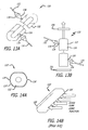
- FIG. 14a shows an end view
- Fig. 14b shows a perspective view of the alternative embodiment of the integrated pump cavity 120' in a side pumped configuration where diode pump light is inserted through slits 126' and 128' that run the entire length of the laser gain length.
- This embodiment is disclosed and claimed in U.S. Patent No. 6,246,711 issued to R. D. Stultz et al. on March 25, 1999, the teachings of which are hereby incorporated herein by reference.
Landscapes
- Physics & Mathematics (AREA)
- Electromagnetism (AREA)
- Engineering & Computer Science (AREA)
- Plasma & Fusion (AREA)
- Optics & Photonics (AREA)
- Lasers (AREA)
Abstract
Description
- The present invention relates to lasers. More specifically, the present invention relates to high-efficiency lasers and methods for fabricating same.
- Highly efficient lasers are needed for applications ranging from active sensors to high-energy lasers for directed energy weapons. Due to the high efficiency thereof, solid-state lasers have proven to be very useful for these applications. Unfortunately, when scaled to high average power levels, waste heat generated by these lasers typically cause thermal gradients in the gain media thereof. As the thermal gradients diminish the quality of the output beam, a heat management system is typically required in conjunction with systems for correcting the beam distortion caused by the waste heat. The waste heat is due to a non-ideal conversion of pump light to laser light. This defect is referred to as a 'quantum defect', the ratio of the photon frequency or energy of the laser divided by the photon frequency or energy of the pump.
- Conventional approaches to the problem of waste heat in solid-state lasers include efforts to increase the efficiency thereof. Neodymium YAG lasers for example have shown efficiencies of approximately 70%, close to the quantum defect thereof. However, the sensible heat for these lasers remains substantial.
- Ytterbium YAG lasers have also shown encouraging efficiency levels at or near 80%. However, scaling of these lasers to kilowatt levels requires a sophisticated thermal management system notwithstanding the efficiency thereof.
- Radiation balanced or non-exothermic laser systems such as that disclosed in U.S. Patent No. 6,370,172, issued April 9, 2002 to S. R. Bowman, the teachings of which are hereby incorporated herein by reference, have been considered. This reference discloses a resonantly pumped laser in which the upper laser state manifold is the level that is being pumped into. That is, in a two level system, the pump manifolds have sublevels known as 'Stark energy levels'. Pumping into the Stark energy levels yields lasing action at different Stark energy levels. This approach is referred to a 'resonant pumping' and Yb3+:YAG and Er3+:YAG lasers - for example - are referred to as 'resonant pumped lasers'.
- With the radiation balanced approach, an Ytterbium (Yb3+) based crystal laser gain medium is chosen so that the pump frequency is lower than the mean florescence frequency so that a balance is achieved whereby the mean florescence frequency is equal to the pump laser frequency plus the laser frequency. Unfortunately, this approach is challenging and problematic in that the florescence rates must be fast enough in order to meet the second requirement: namely, the spontaneous emission rate times the mean fluorescence frequency plus the stimulated emission (laser emission) rate times the laser frequency must be equal to the pumping rate times the pump frequency. Since fluorescence emission is the means for cooling, the gain geometry must be such that the fluorescence emission is effectively dispatched outside the lasing medium in order to prevent re-absorption into the gain medium which would diminish the cooling effect. This typically puts severe restrictions on the laser gain geometry such that at least one optically thin dimension is required.
- Consequently, this approach is heavily dependent on florescence cooling to achieve a low heat laser design. Florescence cooling approaches are limited in that generally, three requirements that must be met: 1) the mean fluorescence frequency must be higher than the pump frequency; 2) the fluorescence rates must be sufficiently high as mentioned above; and 3) the florescence re-absorption must be minimized for the waste heat to escape.
- Hence, a need remains in the art for a highly efficient laser with a substantially reduced need for thermal management.
- The ultra-low heat laser of the present invention addresses the need in the art without reliance on florescence cooling. Generally, the inventive laser includes a pump source operable at a pump frequency and a gain medium disposed to receive energy from the source and lase at a frequency close to the pump frequency.
- In the illustrative embodiment, the laser is a solid-state laser having a gain medium which is resonantly pumped to lase at a frequency within 5% of the pump frequency. However, in the best mode and in accordance with the present teachings, the gain medium lases at a frequency within 1% of the pump frequency.
- In the illustrative embodiment, the laser gain medium ion has a rich Stark energy level structure and the laser active gain medium has oscillator strengths at transitions wavelengths that allow an ultra-low (e.g. 1%) quantum defect operation. The pump source has a wavelength output centered to correspond to a predetermined pump band and an emission band subtended by an absorption bandwidth thereof.
- In addition, a master-oscillator power amplifier (MOPA) is taught. The inventive MOPA includes a laser resonator comprising a first reflective element adapted to transmit radiation received from a pump source and reflect energy at the lasing frequency, a first laser gain medium disposed to receive pump energy via the first reflective optical element means and lase at a frequency close to the pump frequency, a reflective outcoupler in functional alignment with the gain medium and an amplifier chain comprising second and third laser gain mediums, a first transmissive element disposed between the outcoupler and the second laser gain medium, a second transmissive element disposed between the second gain medium and the third gain medium and a third transmissive element disposed at an output end of the third gain medium.
- In the illustrative embodiment, the first reflective element of the amplifier is a volume Bragg grating holographic optical element with an acceptance angle sufficient to provide for high transmission of the pump radiation and narrow spectral selectivity to provide for high reflection of energy at the lasing wavelength. In addition, the first, second and third transmissive elements have narrow acceptance angles with high transmission at the lasing frequency.
- With respect to the MOPA implementation, in the illustrative embodiment, the laser is a solid state laser having a gain medium which is resonantly pumped to lase at a frequency within 5% of the pump frequency. However, in the best mode and in accordance with the present teachings, the gain medium lases at a frequency within 1% of the pump frequency. The laser gain medium active ion has a rich Stark energy level structure and oscillator strengths at transitions/wavelengths that allow an ultra-low (e.g. 1%) quantum defect operation. The pump source has a wavelength output centered to correspond to a predetermined pump band and an emission band subtended by an absorption bandwidth thereof.
- Further, a method for fabricating a laser is taught. The inventive method includes the steps of:
- selecting a laser gain medium (active crystal or amorphous solid) having an optimized Stark energy level structure to satisfy predetermined gain requirements while providing for strong absorption and operation with a minimized quantum defect and reasonable oscillator strength emission bands;
- identifying appreciable oscillator strength transitions and pump band absorptions in the laser gain material; and
- providing a customized pump source for the host with a center wavelength that matches a chosen absorption band in the crystal and has a line width emission that is within an absorption line width of an absorption band thereof.
-
- Fig. 1a and Fig. 1b show a pumping scheme for the 4-level Nd laser in accordance with conventional teachings.
- Fig. 2a is a diagram showing an illustrative Yb:crystal energy level structure.
- Fig. 2b is a diagram showing sample fluorescence/emission spectra for the Yb:crystal of Fig. 2a.
- Fig. 3 is a diagram illustrating the basic principles and requirements behind the operation of a radiation balanced laser.
- Figs. 4a and 4b show illustrative energy level structure of a resonantly pumped laser system. Er:YAG is an example of a laser crystal that has a rich Stark energy level structure in accordance with the present teachings.
- Fig. 5 shows Er:YAG absorption and photoluminescence and the available pump/laser bands combos.
- Figs. 6a and 6b show resonant pump bands and potential laser transitions for Er:YAG lasers.
- Fig. 7 is a diagram which shows an output power performance prediction as a function of input power - comparing four wavelengths/transitions in Er:YAG: 1.645 µm, 1.618 µm, 1.570 µm, and 1.546 µm.
- Fig. 8 is a series of graphs that show the ratio of available (maximum) inversion density to the threshold inversion density for the same resonator parameters/conditions described with respect to Fig. 7 above.
- Figs. 9a and 9b are graphs which illustrate the ratio of available (maximum) inversion density to the threshold inversion density and the predicted output power performance respectively for the 1549 nm pumped 1618 nm and 1570 nm laser bands in Er:YAG.
- Fig. 10a is a simplified diagram of a customized diode laser pump source with a bandgap tuned to a center absorption band wavelength and a bandwidth narrowed to fit within the particular absorption band of the laser in accordance with the present teachings.
- Fig. 10b is a diagram showing the emission band of the laser pump source of Fig 10a showing a match to an Er:YAG absorption band.
- Fig. 11 is a simplified optical schematic showing an end-pumped ULHL laser utilizing customized output wavelength/bandwidth laser pump sources and ultra-high resolution dichroic mirrors in accordance with the present teachings.
- Fig. 12a is a simplified diagram of such a volume Bragg grating holographic optical element implemented in accordance with the present teachings.
- Fig. 12b is a simplified optical schematic showing an alternative embodiment of a laser resonator implemented in accordance with the present teachings for a master oscillator power amplifier MOPA application.
- Fig. 12c shows graphs of Er:YAG absorption and photoluminescence.
- Figs. 13a and 13b show perspective and sectional side views of an integrated pump cavity with multiple pump light insertion points in accordance with the present teachings.
- Fig. 14a shows an end view of the alternative embodiment of the integrated pump cavity of Fig. 13a.
- Fig. 14b shows a perspective view of the alternative embodiment of the integrated pump cavity of Fig. 13a.
- Illustrative embodiments and exemplary applications will now be described with reference to the accompanying drawings to disclose the advantageous teachings of the present invention.
- While the present invention is described herein with reference to illustrative embodiments for particular applications, it should be understood that the invention is not limited thereto. Those having ordinary skill in the art and access to the teachings provided herein will recognize additional modifications, applications, and embodiments within the scope thereof and additional fields in which the present invention would be of significant utility.
- The implementation of a quasi-two level (also known as resonantly pumped) laser provides for potentially the lowest quantum defect (QD) operation - although not necessarily the lowest overall optical efficiency operation. For instance, a Neodymium: crystal (YAG, YVO4, GdVO4, etc.) laser has a quantum defect of ~25% (when pumped at 808 nm) and ~16% (when pumped at 897nm) yet has been demonstrated with optical efficiencies exceeding 70% because it is a 4-level laser which provides for easily achieving near 100% pump absorption efficiency. Specifically, Nd:GdVO4 has been operated with 79% slope efficiency. (See "Researchers Around the World Obtain Vanadate Improvement", by B. Hitz in Photonics Spectra, Jan. 2004.)
- Fig. 1a and Fig. 1b show a pumping scheme for the 4-level Nd laser in accordance with conventional teachings. Quasi-two level lasers exhibit a quasi-three level feature (depending on the lower Stark laser level population), which carries with it a certain amount of pump overhead (in addition to resonator losses) to reach threshold. Also, the resonantly pumped laser scheme bleaching of the transition (at the pump wavelength) typically results in the optimized pump absorption to be less than 100%. Both of these factors typically contribute to an overall efficiency reduction of these quasi-two level (resonantly pumped) laser systems. Nonetheless, the quasi-2 level laser offers a significantly lower quantum defect than conventional 4-level lasers (such as Nd:YAG), which offers robust thermal handling and superior beam quality.
- One of the best known quasi-two level (resonantly pumped) laser system is the Yb:YAG laser which when pumped near 940 nm exhibits a quantum defect of ~9% and a QD of ~6% when pumped near 970 nm. Recent reports show that optical slope efficiencies of ~60% were achieved in Yb:YAG and Yb:FAP and as high as 80% in slightly cooled Yb:GdCOB. (See "Diode pumped tunable Yb:YAG Miniature Lasers At Room Temperature: Modeling And Experiment", by T. Taira et al., IEEE J. Selected Topics Quantum Electron. 3(1), 100 - 103 (1997); "End-pumped Yb-doped Fluoropatite Laser", by R. Scheps et al., IEEE Photonics Tech Lett., 5(11), 1285 - 1288 (1993); and "Theoretical And Experimental Investigation Of A Diode Pumped Three Level Laser: Yb:Gdcob Laser", by F. Auge et al., IEEE J. Quantum Electron. 36(5), 598 - 606 (2000).) An illustrative Yb:crystal energy level structure is shown in Figs. 2a and 2b.
- Fig. 2a is a diagram showing an illustrative Yb:crystal energy level structure. Fig. 2b is a diagram showing a sample fluorescence/emission spectra for the Yb:crystal of Fig. 2a.
- Radiation balanced or non-exothermic lasers are based on quasi-two level resonantly pumped lasers systems. (See "Sensitivity And Stability Of A Radiation Balanced Laser System", by S. Bowman et al., IEEE J. Quantum Electron. 38(10), 1339-1348 (2002); "Self-Cooling Solid State Lasers", S. Andrianov, Proc. SPIE Vol. 5478 (2004); and "Laser Cooling Of Active Media in Solid-State Laser", by S. V. Petrushkin et al., Laser Physics 13(10), 1290 - 1296, 2003.) A fundamental requirement for a zero heat operation of a radiation balanced laser is an efficient fluorescence cooling mechanism.
- Fig. 3 is a diagram illustrating the basic principles and requirements behind the operation of a radiation balanced laser. The conditions/requirements for radiation balanced operation are: i) significant overlap between absorption and fluorescence spectra; ii) νL<νP<νF where νL is the laser frequency, νP is pump frequency, and νF is mean fluorescence frequency; iii) (pump rate) X hνP = (stimulated emission rate) X hνL + (Spontaneous emission rate) X hνF (where h is the Plank constant); iv) the fluorescence lifetime is required to be short (or the spontaneous emission rate has to be high) to minimize the efficiency hit due to fluorescence photon losses; v) the laser gain geometry is required to be optically thin in at least one dimension; and vi) non-radiative loss rate << spontaneous emission rate.
- The fluorescence emission requirements listed above provides for a severely limited implementation of the radiation balanced laser. Crystals such as Yb:KYW show promise of fulfilling these requirements. The above-referenced Bowman patent on non-exothermic lasers lists these requirements and potential crystals that could be utilized for this radiation balanced operation. A key mechanism (and - therefore - limitation) of the radiation balanced laser is the strict adherence of the fluorescence properties to the requirements enumerated above.
- Hence, as stated above, a need exists in the art for a highly efficient laser with a substantially reduced need for thermal management. The need is addressed by the ultra low heat laser (ULHL) and methods of the present invention.
- In the best mode, the inventive ultra-low heat laser (ULHL) employs a resonantly pumped laser such as Yb3+ or Er3+ laser in a crystal host. Those skilled in the art will appreciate that the invention is not limited to a resonantly pumped laser or to the use of a crystal host. An illustrative energy level structure of a resonantly pumped laser system is illustrated in Figs. 4a and 4b. Resonantly pumped lasers have the pumping and laser action occurring between the ground and first excited state
energy level manifolds 1 and2. The energy level manifolds have degeneracy that is split due to the crystal field. These degenerate energy levels are referred to as "Stark" energy levels. The pump and laser action occur then between different Stark energy levels as illustrated in this Figs 4a and 4b. - The advantages of a resonantly pumped laser system are: i) inherently low quantum defect because laser action occurs from within the same manifolds as the pumping and ii) a lower laser energy level resides within the ground state manifold, which essentially eliminates bottlenecking
- The second requirement for an ULHL in accordance with the present teachings is that the laser gain medium/active laser ion have an "rich" Stark energy level structure. Er:YAG - for example - satisfies this condition as it has 8 Stark energy levels in the ground state manifold and 7 in the upper energy level manifold as shown in Fig. 4b. Yb:YAG - by comparison - does not have a rich Stark level structure - as can be seen in Figure 4a.
- The third requirement for an ULHL in accordance with the present teachings is that the laser active gain media have appreciable oscillator strengths/at transitions/wavelengths that will allow an ultra-low quantum defect operation. Ultra - low quantum defect operation is defined as being <5% (preferably 1% or less). This is illustrated in Fig. 5 and in Table I (below) where Er:YAG is used as an example.
Table I λPUMP [nm] Laser wavelength designation λLASER [nm] Quantum defect [% ] 1471 λ 21570 6.3 1471 λ1 1546 4.9 1533 λ5 1645 6.8 1533 λ4 1634 6.2 1533 λ3 1617 5.2 1533 λ 21570 2.4 1533 λ1 1546 0.8 - Fig. 5 shows Er:YAG absorption and photoluminescence and the available pump/laser bands combos. The common (published) 1645 nm laser was demonstrated previously and it operated with ~ 7% QD. The available strong oscillator strength transitions indicated with λ1-6 are a clear indication that Er:YAG has the potential to operate with as low as 0.8% QD. Other crystal hosts for Er3+ may prove even more favorable. Clearly, Er:YAG offers a sufficient number of strong oscillator strengths and is therefore a candidate for ULHL in accordance with the present teachings.
- The resonant pump and potential laser transitions for Er:YAG are shown in Figs. 6a and 6b. In Figs. 6a and 6b, fn are the Boltzmann fractional population densities governed by the Stark energy level and the temperature of the medium - relative to the particular manifold zero energy level.
- The last design requirement for an ULHL in accordance with the present teachings is to implement a fiber laser or a diode laser pump source with a customized wavelength output to be centered to correspond to a particular chosen pump band and to have an emission band narrow enough to be subtended by the absorption bandwidth. In accordance with the present teachings, a fiber laser is customized to achieve these characteristics. A diode laser is first designed with a customized emission wavelength and then implemented with a volume Bragg grating (VBG) reflector in order to narrow and lock the emission wavelength/bandwidth.
- A resonant pumped laser (such as Er in a crystal host) is governed by the Boltzmann Stark energy level distribution, the absorption cross-section at a particular Stark - Stark energy level transition, and -particular Stark - Stark laser transition. Figure 4 shows the available pump and emission lines and the Boltzmann distributions: The Boltzmann probabilities are temperature dependent and are defined as:


- 1. The maximum fractional population of the upper laser state:

where No is the total doping/concentration density of the active ions in the crystal host. This stems from the pump bleaching condition governed by:
where NL and NU are the total lower and upper population densities respectively and
- 2. The fractional population of the upper laser level (manifold) required to obtain transparency at the laser wavelength:

This expression stems from the condition for transparency at the laser wavelength:
- 3. The maximum inversion density:

- The next step is to identify crystal hosts that offer a rich Stark energy level structure to satisfy gain (with strong oscillator strength emission bands) requirements while providing for available absorption bands such that operation with a <5% (goal of 1%) quantum defect is possible. Er:YAG is a suitable candidate for an ultra-low quantum defect operation.
- Fig. 7 is a diagram which shows an output power performance prediction as a function of input power - comparing four wavelengths/transitions in Er:YAG: 1.645µm, 1.618 µm, 1.570 µm, and 1.546µm. In Fig. 7, solid lines represent 1533 nm pumping, single dashed red line represents 1470 nm pumped 1546 nm operation performance.
- As per Fig. 5 above, QD pumping of ~5% or lower can be achieved with both 1533 nm and 1470 nm pumping.
- The modified Pout equation in terms of the appropriate Stark probabilities is written as:

where Roc is output coupler reflectivity; hνL is laser photon energy; d is the mode diameter; τF is the fluorescence lifetime; L represents residual resonator passive losses; l is the laser gain length; Pin is the input power; ηt is the total laser efficiency defined as: ηt = ηQηSηBηB, where the first term is the quantum efficiency, the second term is the Stokes (laser/pump wavelength mismatch), the third term is the mode overlap efficiency, and the fourth term is the absorption efficiency; Nt is the total ion doping density, and σL is the stimulated emission cross-section - Stark level-to-level value. - Fig. 7 shows predicted power performance for a nominal set of resonator conditions for five different low QD transitions in Er:YAG. Pout vs. Pin prediction for resonantly pumped Er:YAG with the following assumptions: laser gain length, l = 10 cm, Roc = 75%, non-saturable resonator losses = 3%, Er doping concentration = 0.5% atomic weight, ηQ = 0.99, ηs = governed by the ratio of pump and lasing wavelength, ηB = 0.85.
- As can be noted, the threshold is very dependent on the pump and lasing Stark energy levels; however, operation point well into the saturated regime (well - above threshold) shows predicted high efficiency of operation. In this regime, it is the minimized sensible heat that will make a drastic difference in the operation of the laser and the thermal management implementation requirements.
- The second metric for gauging the practical implementation of the ultra-low QD operation is the measure of the available inversion to the required threshold inversion governed by the resonator parameters/losses:

- Fig. 8 is a series of graphs which show the ratio of available (maximum) inversion density to the threshold inversion density for the same resonator parameters /conditions described with respect to Fig. 7. Note that even for the 0.8% QD operation, reasonable gain lengths can be allowed in order to implement the ultra-low QD resonantly pumped laser action. In Fig. 8, solid lines represent 1533 nm pumping, single dashed red line represents 1470 nm pumped 1546 nm operation performance.
- It is worth noting that the above analysis utilized the strong absorption bands in Er:YAG. However, ultra low QD operation can also be achieved with the utilization of pump bands that have much weaker absorption. This would require an appropriate design of the pump cavity/laser resonator in accordance with the present teachings in order to ensure efficient coupling of pump radiation.
- One such technique would be the implementation of a long waveguide (flat fiber) where end - pumping is achieved over a long enough length for near 100% absorption.
- A second approach would be the implementation of an efficient integrating pump cavity in order to - again - achieve near 100% pump light absorption. Practical considerations such as imperfect internal reflection coatings and cooling approaches would have to be considered in this case/scenario.
- Figs. 9a and 9b are graphs which illustrate the ratio of available (maximum) inversion density to the threshold inversion density and the predicted output power performance respectively for the 1549 nm pumped 1618 nm and 1570 nm laser bands in Er:YAG. Figs. 9a and 9b show a model for 1549 nm pumped 1570 and 1618 nm laser bands (1.3% and 4.3% QD respectively). The same assumptions/resonator conditions were used as per Fig. 7 - except the assumed gain length is 30 cm.
- In summary, the inventive Ultra-Low Heat Laser (ULHL) described herein should provide minimal reliance on the fluorescence mechanism for cooling and take advantage of a rich Stark energy level structure - such as found in Er:crystals - to achieve (within existing oscillator strengths) ultra-low quantum defect resonant pumped operation. One should endeavor to implement the lowest QD operation on the most suitable laser system (as good or better than Er:YAG).
- The illustrative method for implementing ultra-low quantum defect operation in accordance with the present teachings includes the following steps:
- i) Implementation of a customized pump laser source (such as a diode laser) that operates at a precise design wavelength with a sufficiently narrow bandwidth to match the absorption band of the laser gain medium. For example, customized diode lasers, with external volume Bragg grating (VBG) output couplers, achieve the center wavelength locking in addition to providing a narrow emission bandwidth. This is illustrated in Figs. 10a and 10b.
Fig. 10a is a simplified diagram of a customized diodelaser pump source 10 with a bandgap tuned to a center absorption band wavelength and a bandwidth narrowed to fit within the particular absorption band of the laser in accordance with the present teachings. Fig. 10b is a diagram showing the emission band of the pump laser and the match to the absorption band of the Er:YAG laser - in this example. Thesource 10 is a diode laser array stack tuned to match a desired center wavelength. The stack includes an active medium 20 sandwiched between ahigh reflector 25 and a volume Bragg grating 30. TheVBG 30 is used in place of a conventional reflector coating on the diode array. Hence, wavelength locking and bandwidth narrowing is achieved via volume Bragg grating (VBG) mirror technology.
The laser output is tuned to the center of the absorption peak shown at 50 in Fig. 10b and the emission bandwidth of the pump laser matches the absorption band of the laser gain medium. - ii) Implementation of a robust pump laser light coupling system that allows for high efficiency laser pump light coupling without compromising laser resonator mirror reflectivity. This can be achieved via customized dichroic filters/mirrors and VBG optical elements as shown in Fig. 11.
Fig. 11 is a simplified optical schematic showing an end-pumped ULHL laser utilizing customized output wavelength/bandwidth laser pump sources and ultra-high resolution dichroic mirrors (such as VBGs) in accordance with the present teachings. Thesystem 60 includes first and second fiber coupledpump lasers collimator 68 by afiber pigtail 66. In the best mode, thelasers source 10 of Fig. 10a. Thecollimators 68feed lenses dichroic beam splitter 76 and adichroic mirror 90 respectively onto a resonantly pumpedlaser gain medium 80 implemented in accordance with the present teachings (See Figs. 13 and 14.) That is, in accordance with the present teachings, the laser is designed to lase at a wavelength close to that of the pump source, i.e., within 5% and in the best mode, within 1% thereof. The dichroic mirrors pass pump wavelengths and reflect lasing wavelengths. - In the best mode of practicing the invention, the
dichroic mirror 90 is implemented with a customized volume Bragg grating holographic optical element (VBG HOE). The VBGoptical element 90 is an ultra-high resolution multiplexing device which will efficiently transmits pump light as little as several nanometers away from the laser line spectrally, while acting as a high reflector at the laser line/wavelength. Because end-pumping is desirable especially in the case of lower absorption coefficients, pump light multiplexing can be implemented through the customized VBG HOE (holographic optical element) with angle and polarization multiplexing techniques. - Fig. 12a is a simplified diagram of such a VBG holographic optical element (HOE) implemented in accordance with the present teachings. The
inventive VBG HOE 90 is a high-resolution dichroic optical element with very select band reflectivity (i.e. approximately 100% reflection with narrow spectral selectivity) at the laser line with a relatively large acceptance angle for high (i.e. approximately 100%) transmissivity at the pump wavelength. TheVBG HOE 90 is fabricated by a specialized arrangement that writes customized holographic gratings in a sensitized high optical damage threshold glass material. - Returning briefly to Fig. 11, a broadband
output coupler reflector 84 allows use of an intra-cavity tuning element such as anEtalon 82 to select a desired wavelength as the output beam. - Fig. 12b is a simplified optical schematic showing an alternative embodiment of a laser resonator implemented in accordance with the present teachings for a master oscillator power amplifier (MOPA) application. As shown in Fig. 12b, the
MOPA 80 includes alaser resonator 102 including theVBG HOE 90, a reflectiveVBG output coupler 104 and again medium 106. TheVBG HOE 90 is used for efficiently multiplexing pump light that is very close in frequency to the laser light (in the end-pumping arrangement). The transmissiveVBG HOE elements resonator 102 feeds anamplifier chain 108 consisting of first, second and thirdtransmissive VBG elements third gain media amplifier chain 108 utilizes theVBGs - Since resonant pumped lasers such as Er:YAG are relatively low gain systems, the oscillator strengths thereof are roughly similar. Therefore, a relatively small degree of suppression will achieve the goal of selecting the desired laser line and suppressing the remaining competing lines. This can be achieved with the utilization of an output coupler that is a volume Bragg grating (VBG) transmissive optical element which only has a finite appreciable reflectivity at the wavelength of choice and near zero reflectivity at the competing laser lines (wavelengths). The VBG elements can be incorporated both as reflective and transmissive types that can provide a venue for robust MOPA implementation as well. The efficient coupling of the pump light is also achieved with the customized
VBG element 90. - Fig. 12c shows graphs of Er:YAG absorption and photoluminescence. These figures show a method for invoking ultra-low quantum defect operation in ULHL (Er:YAG shown as a spectroscopy example) in accordance with the present teachings. Selective output coupler reflectivity is based on a VBG optical element.
- Figs. 13a and 13b show an implementation of an integrating pump cavity approach in which a long integrating pump cavity with multiple pump light insertion points for near 100% pump light absorption for use in cases where the pump wavelength chosen has an inherently low absorption coefficient. Fig. 13a is a perspective view of the
integrated pump cavity 120 adapted for use in thelaser resonators reflective coating 124 is provided for internal reflection of pump light. Multiple insertion points 126, 128 are provided to receive pump light fromfibers lens output coupler 199 and ahigh reflector 201. - A more conventional integrating pump cavity approach is shown in Figs. 14a and 14b. Fig. 14a shows an end view and Fig. 14b shows a perspective view of the alternative embodiment of the integrated pump cavity 120' in a side pumped configuration where diode pump light is inserted through
slits 126' and 128' that run the entire length of the laser gain length. This embodiment is disclosed and claimed in U.S. Patent No. 6,246,711 issued to R. D. Stultz et al. on March 25, 1999, the teachings of which are hereby incorporated herein by reference. - Thus, the present invention has been described herein with reference to a particular embodiment for a particular application. Those having ordinary skill in the art and access to the present teachings will recognize additional modifications applications and embodiments within the scope thereof.
- It is therefore intended by the appended claims to cover any and all such applications, modifications and embodiments within the scope of the present invention.
Accordingly,
Claims (10)
- A laser (60) characterized by:a pump source (62, 64) operable at a pump frequency anda gain medium (80) disposed to receive energy from said source (62, 64) and adapted to lase at a frequency close to said pump frequency.
- The invention of Claim 1 wherein said frequency at which said gain medium lases is within 5% of the pump frequency.
- The invention of Claim 1 wherein said gain medium is resonantly pumped.
- The invention of Claim 1 wherein said laser (60) is a solid-state laser.
- The invention of Claim 1 wherein the laser gain medium (80) has an ion with a rich Stark energy level structure.
- The invention of Claim 1 wherein said laser active gain medium (80) has oscillator strengths at transitions wavelengths that allows an ultra-low quantum defect operation.
- The invention of Claim 6 wherein said ultra-low quantum defect operation is <5%.
- The invention of Claim 1 wherein said pump source (62, 64) has a wavelength output centered to correspond to a predetermined pump band.
- The invention of Claim 8 wherein said pump source (62, 64) has an emission band subtended by an absorption bandwidth thereof.
- The invention of Claim 1 wherein said laser (60) has an Erbium activated crystalline or amorphous solid host.
Applications Claiming Priority (1)
| Application Number | Priority Date | Filing Date | Title |
|---|---|---|---|
| US11/040,220 US7391796B1 (en) | 2005-01-21 | 2005-01-21 | Ultra-low heat laser |
Publications (2)
| Publication Number | Publication Date |
|---|---|
| EP1684392A1 true EP1684392A1 (en) | 2006-07-26 |
| EP1684392B1 EP1684392B1 (en) | 2007-10-31 |
Family
ID=35709047
Family Applications (1)
| Application Number | Title | Priority Date | Filing Date |
|---|---|---|---|
| EP05257428A Expired - Lifetime EP1684392B1 (en) | 2005-01-21 | 2005-12-02 | Ultra-low heat laser |
Country Status (3)
| Country | Link |
|---|---|
| US (2) | US7391796B1 (en) |
| EP (1) | EP1684392B1 (en) |
| DE (1) | DE602005003099T2 (en) |
Families Citing this family (8)
| Publication number | Priority date | Publication date | Assignee | Title |
|---|---|---|---|---|
| US20110044359A1 (en) * | 2009-08-18 | 2011-02-24 | Douglas Llewellyn Butler | Intracavity Conversion Utilizing Narrow Band Reflective SOA |
| DE102010036286A1 (en) | 2010-08-31 | 2012-03-01 | Friedrich-Schiller-Universität Jena | Method and apparatus for thermal stabilization of a rare earth laser with reduced cooling and thermal degradation |
| CN102723421B (en) * | 2012-01-30 | 2014-12-10 | 深圳市光峰光电技术有限公司 | Wavelength conversion apparatus and luminous apparatus |
| WO2018102738A1 (en) * | 2016-12-01 | 2018-06-07 | Ipg Photonics Corporation | High-power, rare-earth-doped crystal amplifier based on ultra-low-quantum-defect pumping scheme utilizing single or low-mode fiber lasers |
| US11641090B2 (en) * | 2020-07-17 | 2023-05-02 | Raytheon Company | High-pulse energy, high-power lasers with diffraction-limited performance |
| US11885967B2 (en) * | 2020-11-05 | 2024-01-30 | Meta Platforms Technologies, Llc | Phase structure on volume Bragg grating-based waveguide display |
| CN112993733B (en) * | 2021-02-02 | 2022-06-03 | 长春理工大学 | Light-operated wavelength selection pumping source based on Er-YAG mid-infrared parametric oscillator |
| WO2025160496A1 (en) * | 2024-01-25 | 2025-07-31 | Trustees Of Boston University | Stimulated raman photothermal microscope with optical parametric amplifier source |
Citations (5)
| Publication number | Priority date | Publication date | Assignee | Title |
|---|---|---|---|---|
| US4995046A (en) * | 1989-08-23 | 1991-02-19 | Laserqenics | Room temperature 1.5 μm band quasi-three-level laser |
| DE4142704A1 (en) * | 1991-11-14 | 1993-05-19 | Daimler Benz Ag | Laser diode modulator - has laser active zone pumped by pump light of equal or smaller wavelength. Preferably a second laser beam. |
| US5287378A (en) * | 1992-12-30 | 1994-02-15 | The United States Of America As Represented By The Secretary Of The Navy | Holmium quasi-two level laser |
| US6246711B1 (en) | 1999-03-25 | 2001-06-12 | Raytheon Company | Integrating diode pump cavity for an Er, Yb:glass laser |
| US6370172B1 (en) | 1999-12-27 | 2002-04-09 | The United States Of America As Represented By The Secretary Of The Navy | Non-exothermic quasi-two level laser |
Family Cites Families (1)
| Publication number | Priority date | Publication date | Assignee | Title |
|---|---|---|---|---|
| GB8829875D0 (en) * | 1988-12-22 | 1989-02-15 | Lumonics Ltd | Optically pumped lasers |
-
2005
- 2005-01-21 US US11/040,220 patent/US7391796B1/en not_active Expired - Lifetime
- 2005-12-02 DE DE602005003099T patent/DE602005003099T2/en not_active Expired - Lifetime
- 2005-12-02 EP EP05257428A patent/EP1684392B1/en not_active Expired - Lifetime
-
2008
- 2008-05-07 US US12/151,551 patent/US7633991B2/en not_active Expired - Lifetime
Patent Citations (5)
| Publication number | Priority date | Publication date | Assignee | Title |
|---|---|---|---|---|
| US4995046A (en) * | 1989-08-23 | 1991-02-19 | Laserqenics | Room temperature 1.5 μm band quasi-three-level laser |
| DE4142704A1 (en) * | 1991-11-14 | 1993-05-19 | Daimler Benz Ag | Laser diode modulator - has laser active zone pumped by pump light of equal or smaller wavelength. Preferably a second laser beam. |
| US5287378A (en) * | 1992-12-30 | 1994-02-15 | The United States Of America As Represented By The Secretary Of The Navy | Holmium quasi-two level laser |
| US6246711B1 (en) | 1999-03-25 | 2001-06-12 | Raytheon Company | Integrating diode pump cavity for an Er, Yb:glass laser |
| US6370172B1 (en) | 1999-12-27 | 2002-04-09 | The United States Of America As Represented By The Secretary Of The Navy | Non-exothermic quasi-two level laser |
Non-Patent Citations (10)
| Title |
|---|
| B. HITZ: "Researchers Around the World Obtain Vanadate Improvement", PHOTONICS SPECTRA, January 2004 (2004-01-01) |
| F. AUGE: "Theoretical And Experimental Investigation Of A Diode Pumped Three Level Laser: Yb:Gdcob Laser", IEEE J. QUANTUM ELECTRON., vol. 36, no. 5, 2000, pages 598 - 606 |
| J. PETIT ET AL.: "Laser oscillation with low quantum defect in Yb:GdVO4, a crystal with high thermal conductivity", OPTICS LETTERS OPT. SOC. AMERICA USA, vol. 29, no. 8, 15 April 2004 (2004-04-15), pages 833 - 835, XP002367009, ISSN: 0146-9592 * |
| J. PETIT ET AL.: "Optical spectroscopy and laser oscillation in a high power laser material: Yb:GdVO4", SOLID STATE LASERS AND AMPLIFIERS 27-29 APRIL 2004 STRASBOURG, FRANCE, vol. 5460, no. 1, April 2004 (2004-04-01), Proceedings of the SPIE - The International Society for Optical Engineering SPIE-Int. Soc. Opt. Eng USA, pages 132 - 140, XP002367010, ISSN: 0277-786X * |
| R. SCHEPS: "End-pumped Yb-doped Fluoropatite Laser", IEEE PHOTONICS TECH LETT., vol. 5, no. 11, 1993, pages 1285 - 1288 |
| S. ANDRIANOV: "Self-Cooling Solid State Lasers", PROC. SPIE, vol. 5478, 2004 |
| S. BOWMAN: "Sensitivity And Stability Of A Radiation Balanced Laser System", IEEE J. QUANTUM ELECTRON., vol. 38, no. 10, 2002, pages 1339 - 1348 |
| S. V. PETRUSHKIN: "Laser Cooling Of Active Media in Solid-State Laser", LASER PHYSICS, vol. 13, no. 10, 2003, pages 1290 - 1296 |
| SCHMID MARC ET AL: "Optical in-well pumping of a vertical-external-cavity surface-emitting laser", APPLIED PHYSICS LETTERS, AIP, AMERICAN INSTITUTE OF PHYSICS, MELVILLE, NY, US, vol. 84, no. 24, 14 June 2004 (2004-06-14), pages 4860 - 4862, XP012061758, ISSN: 0003-6951 * |
| T. TAIRA: "Diode pumped tunable Yb:YAG Miniature Lasers At Room Temperature: Modeling And Experiment", IEEE J. SELECTED TOPICS QUANTUM ELECTRON., vol. 3, no. 1, 1997, pages 100 - 103 |
Also Published As
| Publication number | Publication date |
|---|---|
| US20080130703A1 (en) | 2008-06-05 |
| DE602005003099T2 (en) | 2008-08-14 |
| US7391796B1 (en) | 2008-06-24 |
| US7633991B2 (en) | 2009-12-15 |
| DE602005003099D1 (en) | 2007-12-13 |
| EP1684392B1 (en) | 2007-10-31 |
| US20080212629A1 (en) | 2008-09-04 |
Similar Documents
| Publication | Publication Date | Title |
|---|---|---|
| US7633991B2 (en) | Ultra-low heat laser | |
| Risk | Modeling of longitudinally pumped solid-state lasers exhibiting reabsorption losses | |
| Scheife et al. | Advances in up-conversion lasers based on Er3+ and Pr3+ | |
| Valley | Modeling cladding-pumped Er/Yb fiber amplifiers | |
| Loiko et al. | Comparative spectroscopic and thermo-optic study of Tm: Li Ln F4 (Ln= Y, Gd, and Lu) crystals for highly-efficient microchip lasers at~ 2 μm | |
| US6891878B2 (en) | Eye-safe solid state laser system and method | |
| US5666373A (en) | Laser having a passive pulse modulator and method of making same | |
| US7813394B2 (en) | Laser with gain medium suppressing higher order modes to provide lasing output with high beam quality | |
| US9658513B2 (en) | Device and method for converting a light and a laser system | |
| Levoshkin et al. | High-efficiency diode-pumped Q-switched Yb: Er: glass laser | |
| US20190280456A1 (en) | Cascaded, long pulse and continuous wave raman lasers | |
| Jiang et al. | High-performance diode-end-pumped Nd: YLF laser operating at 1314 nm | |
| US7046710B2 (en) | Gain boost with synchronized multiple wavelength pumping in a solid-state laser | |
| EP1130702B1 (en) | Method and device for laser amplification | |
| Sacks et al. | Long-wavelength operation of double-clad Tm: silica-fiber lasers | |
| US7672346B1 (en) | Narrow spectral width lasers optimized and temperature stabilized with volume Bragg grating mirrors | |
| US6370172B1 (en) | Non-exothermic quasi-two level laser | |
| US6587496B1 (en) | Single-mode pump power source | |
| Kieleck et al. | Investigations of a Q-switched Ho: YAG laser intracavity-pumped by a diode-pumped Tm: YLF laser | |
| EP1030416A2 (en) | Laser amplifier and laser oscillator | |
| Spariosu et al. | All solid-state room temperature Er: YAG laser operating at 1617 nm | |
| Eichler et al. | Solid-State Lasers | |
| Selvas et al. | Tuning characteristics of cladding-pumped Neodymium-doped fiber laser | |
| Loiko et al. | Highly-efficient multi-watt Yb: CaLnAlO4 microchip lasers | |
| Georges et al. | Nd concentration optimization for efficient low-cost 473-nm diode-pumped Nd: YAG/KNbO3 microchip assembly |
Legal Events
| Date | Code | Title | Description |
|---|---|---|---|
| PUAI | Public reference made under article 153(3) epc to a published international application that has entered the european phase |
Free format text: ORIGINAL CODE: 0009012 |
|
| AK | Designated contracting states |
Kind code of ref document: A1 Designated state(s): AT BE BG CH CY CZ DE DK EE ES FI FR GB GR HU IE IS IT LI LT LU LV MC NL PL PT RO SE SI SK TR |
|
| AX | Request for extension of the european patent |
Extension state: AL BA HR MK YU |
|
| 17P | Request for examination filed |
Effective date: 20070111 |
|
| AKX | Designation fees paid |
Designated state(s): DE FR GB |
|
| GRAP | Despatch of communication of intention to grant a patent |
Free format text: ORIGINAL CODE: EPIDOSNIGR1 |
|
| GRAS | Grant fee paid |
Free format text: ORIGINAL CODE: EPIDOSNIGR3 |
|
| GRAA | (expected) grant |
Free format text: ORIGINAL CODE: 0009210 |
|
| AK | Designated contracting states |
Kind code of ref document: B1 Designated state(s): DE FR GB |
|
| REG | Reference to a national code |
Ref country code: GB Ref legal event code: FG4D |
|
| REF | Corresponds to: |
Ref document number: 602005003099 Country of ref document: DE Date of ref document: 20071213 Kind code of ref document: P |
|
| ET | Fr: translation filed | ||
| PLBE | No opposition filed within time limit |
Free format text: ORIGINAL CODE: 0009261 |
|
| STAA | Information on the status of an ep patent application or granted ep patent |
Free format text: STATUS: NO OPPOSITION FILED WITHIN TIME LIMIT |
|
| 26N | No opposition filed |
Effective date: 20080801 |
|
| PGFP | Annual fee paid to national office [announced via postgrant information from national office to epo] |
Ref country code: FR Payment date: 20101224 Year of fee payment: 6 |
|
| PGFP | Annual fee paid to national office [announced via postgrant information from national office to epo] |
Ref country code: GB Payment date: 20101201 Year of fee payment: 6 |
|
| PGFP | Annual fee paid to national office [announced via postgrant information from national office to epo] |
Ref country code: DE Payment date: 20101124 Year of fee payment: 6 |
|
| GBPC | Gb: european patent ceased through non-payment of renewal fee |
Effective date: 20111202 |
|
| REG | Reference to a national code |
Ref country code: FR Ref legal event code: ST Effective date: 20120831 |
|
| REG | Reference to a national code |
Ref country code: DE Ref legal event code: R119 Ref document number: 602005003099 Country of ref document: DE Effective date: 20120703 |
|
| PG25 | Lapsed in a contracting state [announced via postgrant information from national office to epo] |
Ref country code: DE Free format text: LAPSE BECAUSE OF NON-PAYMENT OF DUE FEES Effective date: 20120703 Ref country code: GB Free format text: LAPSE BECAUSE OF NON-PAYMENT OF DUE FEES Effective date: 20111202 |
|
| PG25 | Lapsed in a contracting state [announced via postgrant information from national office to epo] |
Ref country code: FR Free format text: LAPSE BECAUSE OF NON-PAYMENT OF DUE FEES Effective date: 20120102 |