EP1684385A2 - Electric system for railway car - Google Patents
Electric system for railway car Download PDFInfo
- Publication number
- EP1684385A2 EP1684385A2 EP06090004A EP06090004A EP1684385A2 EP 1684385 A2 EP1684385 A2 EP 1684385A2 EP 06090004 A EP06090004 A EP 06090004A EP 06090004 A EP06090004 A EP 06090004A EP 1684385 A2 EP1684385 A2 EP 1684385A2
- Authority
- EP
- European Patent Office
- Prior art keywords
- satellite
- plug
- contact
- complementary
- guide ring
- Prior art date
- Legal status (The legal status is an assumption and is not a legal conclusion. Google has not performed a legal analysis and makes no representation as to the accuracy of the status listed.)
- Withdrawn
Links
Images

Classifications
-
- H—ELECTRICITY
- H01—ELECTRIC ELEMENTS
- H01R—ELECTRICALLY-CONDUCTIVE CONNECTIONS; STRUCTURAL ASSOCIATIONS OF A PLURALITY OF MUTUALLY-INSULATED ELECTRICAL CONNECTING ELEMENTS; COUPLING DEVICES; CURRENT COLLECTORS
- H01R9/00—Structural associations of a plurality of mutually-insulated electrical connecting elements, e.g. terminal strips or terminal blocks; Terminals or binding posts mounted upon a base or in a case; Bases therefor
- H01R9/03—Connectors arranged to contact a plurality of the conductors of a multiconductor cable, e.g. tapping connections
-
- B—PERFORMING OPERATIONS; TRANSPORTING
- B60—VEHICLES IN GENERAL
- B60D—VEHICLE CONNECTIONS
- B60D1/00—Traction couplings; Hitches; Draw-gear; Towing devices
- B60D1/58—Auxiliary devices
- B60D1/62—Auxiliary devices involving supply lines, electric circuits, or the like
-
- B—PERFORMING OPERATIONS; TRANSPORTING
- B61—RAILWAYS
- B61G—COUPLINGS; DRAUGHT AND BUFFING APPLIANCES
- B61G5/00—Couplings for special purposes not otherwise provided for
- B61G5/06—Couplings for special purposes not otherwise provided for for, or combined with, couplings or connectors for fluid conduits or electric cables
-
- H—ELECTRICITY
- H01—ELECTRIC ELEMENTS
- H01R—ELECTRICALLY-CONDUCTIVE CONNECTIONS; STRUCTURAL ASSOCIATIONS OF A PLURALITY OF MUTUALLY-INSULATED ELECTRICAL CONNECTING ELEMENTS; COUPLING DEVICES; CURRENT COLLECTORS
- H01R2201/00—Connectors or connections adapted for particular applications
- H01R2201/26—Connectors or connections adapted for particular applications for vehicles
-
- H—ELECTRICITY
- H01—ELECTRIC ELEMENTS
- H01R—ELECTRICALLY-CONDUCTIVE CONNECTIONS; STRUCTURAL ASSOCIATIONS OF A PLURALITY OF MUTUALLY-INSULATED ELECTRICAL CONNECTING ELEMENTS; COUPLING DEVICES; CURRENT COLLECTORS
- H01R27/00—Coupling parts adapted for co-operation with two or more dissimilar counterparts
Definitions
- the invention relates to an electrical system for a rail vehicle having at least two interconnected carriages, wherein each carriage is spanned by power supply lines and / or data lines from one end of the car to the other end of the car, the power supply lines and / or data lines of different carriages being interconnected via a cable connection, wherein the cable connection has at least one plug part and a device part which is complementary to the plug part, the plug part having a substantially hollow-cylindrical guide ring and the device part having a guide cutout complementary to the guide ring.
- UIC plug connection It is typically an 18-pin connector, wherein the contact pairs both power supply lines and data lines of different cars are contacted with each other.
- the invention is therefore based on the technical problem of providing a connector for rail vehicles, which is improved in terms of the performance of data lines, at the same time backward compatibility is ensured.
- the plug part has, outside the guide ring and spaced therefrom, a satellite plug element extending parallel to the guide ring, and the appliance part has a satellite device element complementary to the satellite plug element, the satellite plug element having at least one satellite plug contact and the satellite device element a satellite device contact, wherein the satellite plug contact and the satellite device contact are designed as complementary satellite contact pair.
- a connector used according to the invention allows the installation of additional lines, in particular data lines in a car or a rail vehicle formed from several cars. Because the satellite plug-in element is arranged outside the guide ring and at a distance therefrom, a plug part according to the invention can also still be plugged onto a conventional UIC device part. In this case, the satellite plug contact then remains uncontacted in the absence of a satellite device element. The same applies of course vice versa in the case of a device part according to the invention, in which a conventional UIC plug part is introduced. This achieves mechanical and electrical backward compatibility.
- equipment parts are installed at both ends of the wagon of a wagon, with two opposite parts of the equipment of different wagons being connected to each other via a cable connection equipped with two parts are connected.
- the connecting cable is permanently installed at one end of the car and at the other end has a plug part which is inserted into a device part of an opposite end of the car.
- the guide ring of a plug part and the guide recess complementary thereto are essentially hollow-cylindrical in the sense that polygons can also be used.
- a satellite contact pair can be designed either as an electrical contact pair or as an optical contact pair.
- the use of an optical contact pair is advantageous in that optical data lines have a considerably increased bandwidth compared to electrical data lines, i.e. the data transfer rates are considerably increased.
- the satellite device element and the satellite plug-in element may have from two to ten satellite contact pairs. These satellite contact pairs can also be set up in the context of several satellite device elements and satellite plug-in elements.
- the plug part has a plurality of, preferably two satellite plug elements lying opposite one another with respect to a center axis of the guide ring, wherein the device part has satellite device elements complementary to the satellite plug elements. This can be a total of a plurality of electrical or optical contact pairs and thus upgrade data lines in addition to the 18 poles of conventional UIC connectors.
- each carriage has a central processor unit, wherein at least one data line with a satellite device contact and / or a satellite plug contact is connected.
- a test routine can be carried out, by means of which it is detectable whether a plug-in plug-in connector part and device part to a satellite device element or satellite connector complementary satellite connector or satellite device element is contacted.
- the test routine tests whether, after production of the plug connection, an inventive satellite device element or satellite plug-in element has "found” a complementary satellite element. If so, the data communication between processor units of different cars is via the contacted satellite contact pair.
- the processor unit of a car with a satellite device element or satellite plug element according to the invention converts the operating program to routines which work with the conventional UIC plug-in connection. Thus, a functional backward compatibility is established.
- an electrical system for a rail vehicle wherein additional optical conductors are not arranged in the context of satellite elements, but rather in geometrically free areas of the insulating body of the male member and the device element or instead of a (conventional) pin and a contact socket.
- This can be set up, for example, in the case of UIC plug connections.
- complementary optical terminations or ends are set up in the respective insulators. It thus creates a hybrid UIC connector, wherein in addition to the electrical contact pairs and / or instead of one or more electrical Contact pairs an optical pair of contacts is set up, but no satellite elements are needed (but may be present). Otherwise, the above statements apply analogously, in particular with regard to backward compatibility.
- the opposite ends of the optical conductors are each provided with an optical diffusing lens, which cause an expansion of the light emitted from one end and a focusing of the expanded light received from the opposite end .
- an optical diffusing lens which cause an expansion of the light emitted from one end and a focusing of the expanded light received from the opposite end .
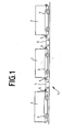
- Figure 1 can be seen a rail vehicle 1 with three interconnected car 2, each car is spanned by power supply lines 3 and data lines 3 from one end of the car to the other end of the car.
- the power supply lines and data lines are not shown separately in this schematic representation.
- the power supply lines 3 and data lines 3 of different cars are connected to each other via the cable connection 4.
- Each cable connection 4 has at opposite ends in each case a plug part 6.
- a Stekkerteil 6 a cable connection 4 is inserted into a device part 5 opposite each other car ends.
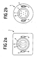
- FIG. 2 as well as a comparative examination of the figure parts 2a and 2b shows that the plug part 6 has a substantially hollow-cylindrical guide ring 7 and the device part 5 has a guide recess 8 complementary to the guide ring 7.
- the plug part 6 has outside of the guide ring 7 and spaced therefrom a parallel to the guide ring 7 extending Satellite plug 9 on.
- the device part 5 has a satellite plug element 9 complementary satellite device element 10.
- the device part 5 has an insulating body 14, in which electrical contact sockets 15 are embedded.
- the plug part 6 likewise has an insulating body 16, but contact pins 17 project beyond this insulating body 16.
- each satellite plug-in element 9 has two satellite plug-in contacts 11 and each satellite device element 10 has two satellite device contacts 12, the satellite plug contacts 11 and the satellite device contacts 12 forming pairs of satellite contact pairs complementary to each other. At least one satellite contact pair is designed as an optical contact pair.
- the two satellite plug-in elements 9 are relative to each other with respect to the central axis of the guide ring 7.
- the satellite device elements 10 are set up in a complementary manner within the scope of the device part 5.
- FIG. 4 shows a connection between two carriages of a rail vehicle, wherein one of the two carriages (on the right side) has a conventional UIC device part. Due to the geometric design, as in the figures 2 3 and 3, the right-side plug part 6 of the cable connection 4 can be inserted into the conventional UIC device part 5 of the right-hand car 2. Both carriages 2 each have a central processor 13. After the preparation of the cable connection 4, the central processor 13 of the left-side car checks whether it is possible to communicate with the central processor 13 of the right-hand sidecar via the data line 3 of the cable connection 4.
- a plug connection used according to the invention can be all mechanical Have features of a conventional UIC connection, in particular also snap cover and lever lock in the context of a device part. 5
Abstract
Description
Die Erfindung betrifft ein elektrisches System für ein Schienenfahrzeug mit zumindest zwei miteinander verbundenen Wagen, wobei jeder Wagen von Stromversorgungsleitungen und/oder Datenleitungen von einem Wagenende zum anderen Wagenende durchspannt ist, wobei die Stromversorgungsleitungen und/oder Datenleitungen verschiedener Wagen über eine Kabelverbindung miteinander verbunden sind, wobei die Kabelverbindung zumindest ein Steckerteil und ein zum Steckerteil komplementäres Geräteteil aufweist, wobei das Steckerteil einen im Wesentlichen hohlzylinderförmigen Führungsring und das Geräteteil eine zum Führungsring komplementäre Führungsausnehmung aufweist.The invention relates to an electrical system for a rail vehicle having at least two interconnected carriages, wherein each carriage is spanned by power supply lines and / or data lines from one end of the car to the other end of the car, the power supply lines and / or data lines of different carriages being interconnected via a cable connection, wherein the cable connection has at least one plug part and a device part which is complementary to the plug part, the plug part having a substantially hollow-cylindrical guide ring and the device part having a guide cutout complementary to the guide ring.
Aus der Praxis ist das eingangs genannte elektrische System bekannt, wobei das Steckerteil sowie das Geräteteil als sog. UIC-Steckverbindung bezeichnet ist. Es handelt sich typischerweise um eine 18-polige Steckverbindung, wobei über die Kontaktpaare sowohl Stromversorgungsleitungen als auch Datenleitungen verschiedener Wagen miteinander kontaktiert werden.From practice, the electrical system mentioned above is known, wherein the plug part and the device part is referred to as so-called. UIC plug connection. It is typically an 18-pin connector, wherein the contact pairs both power supply lines and data lines of different cars are contacted with each other.
Die insofern bekannte Steckverbindung hat sich in der Praxis gut bewährt. Im Zuge der Einführung neuer Technologien in Schienenfahrzeugen, insbesondere Technologien der Kommunikationstechnik, sind jedoch die vorhandenen Datenleitungen in ihrer Anzahl sowie der nutzbaren Bandbreite nicht mehr ausreichend. Die Begrenzung der Bandbreite hängt im Wesentlichen damit zusammen, dass die Datenleitungen mit elektrischen Leitern arbeiten.The far-known connector has proven itself in practice well. In the course of the introduction of new technologies in rail vehicles, in particular technologies of communication technology, however, the existing data lines are not in their number and the usable bandwidth more adequate. The limitation of the bandwidth is essentially related to the fact that the data lines work with electrical conductors.
Grundsätzlich wäre eine Aufrüstung durch Ersatz der UIC-Steckverbindungen durch leistungsfähigere Steckverbindungen, beispielsweise mit einer höheren Anzahl Kontaktpaare oder Ersatz von Kontaktpaaren durch Kontaktpaare von optischen Wellenleitern, möglich. Dies würde jedoch eine gleichzeitige Umrüstung aller im Bestand befindlichen Wagen bzw. Schienenfahrzeuge erforderlich machen mit der Folge, dass beträchtlicher Umrüstungsaufwand besteht. Hinzu kommt, dass eine internationale Kompatibilität im grenzüberschreitenden Schienenfahrzeugverkehr entfallen würde.Basically, an upgrade by replacing the UIC connectors by more powerful connectors, for example, with a higher number of contact pairs or replacement of contact pairs by contact pairs of optical waveguides, possible. However, this would require a simultaneous conversion of all existing wagons or rail vehicles with the result that there is considerable conversion effort. In addition, there would be no international compatibility in cross-border railway traffic.
Wünschenswert wäre daher eine Verbesserung der bekannten UIC-Steckverbindung, wobei insbesondere Abwärtskompatibilität gewährleistet wäre, i.e. dass auch eine Verbindung beispielsweise eines aufgerüsteten Steckerteils mit einem regulären UIC-Geräteteil sowohl mechanisch als auch elektrisch bzw. kommunikationstechnisch möglich ist.It would therefore be desirable to improve the known UIC connector, in particular to ensure backward compatibility, i. that a connection, for example, an upgraded connector part with a regular UIC device part both mechanically and electrically or communication technology is possible.
Der Erfindung liegt daher das technische Problem zugrunde, eine Steckverbindung für Schienenfahrzeuge anzugeben, welche in Hinblick auf die Leistungsfähigkeit von Datenleitungen verbessert ist, wobei gleichzeitig Abwärtskompatibilität gewährleistet wird.The invention is therefore based on the technical problem of providing a connector for rail vehicles, which is improved in terms of the performance of data lines, at the same time backward compatibility is ensured.
Grundzüge der Erfindung und bevorzugte AusführungsformenBroad features of the invention and preferred embodiments
Zur Lösung dieses technischen Problems lehrt die Erfindung, dass das Steckerteil außerhalb des Führungsrings und hierzu beabstandet ein sich parallel zum Führungsring erstreckenden Satellitensteckelement aufweist und dass das Geräteteil ein zum Satellitensteckelement komplementäres Satellitengeräteelement aufweist, wobei das Satellitensteckelement zumindest einen Satellitensteckkontakt und das Satellitengeräteelement einen Satellitengerätekontakt aufweist, wobei der Satellitensteckkontakt und der Satellitengerätekontakt als zueinander komplementäres Satellitenkontaktpaar ausgebildet sind.To solve this technical problem, the invention teaches that the plug part has, outside the guide ring and spaced therefrom, a satellite plug element extending parallel to the guide ring, and the appliance part has a satellite device element complementary to the satellite plug element, the satellite plug element having at least one satellite plug contact and the satellite device element a satellite device contact, wherein the satellite plug contact and the satellite device contact are designed as complementary satellite contact pair.
Eine erfindungsgemäß eingesetzte Steckverbindung erlaubt die Einrichtung zusätzlicher Leitungen, insbesondere Datenleitungen in einem Wagen bzw. einem aus mehreren Wagen gebildeten Schienenfahrzeug. Dadurch, dass das Satellitensteckelement außerhalb des Führungsrings und hierzu beabstandet angeordnet ist, kann ein erfindungsgemäßes Steckerteil auch nach wie vor auf ein herkömmliches UIC-Geräteteil aufgesteckt werden. Hierbei bleibt dann der Satellitensteckkontakt mangels Anwesenheit eines Satellitengeräteelements unkontaktiert. Entsprechendes gilt selbstverständlich umgekehrt im Falle eines erfindungsgemäßen Geräteteils, in welches ein herkömmliches UIC-Steckerteil eingeführt wird. Hierdurch wird eine mechanische und elektrische Abwärtskompatibilität erreicht.A connector used according to the invention allows the installation of additional lines, in particular data lines in a car or a rail vehicle formed from several cars. Because the satellite plug-in element is arranged outside the guide ring and at a distance therefrom, a plug part according to the invention can also still be plugged onto a conventional UIC device part. In this case, the satellite plug contact then remains uncontacted in the absence of a satellite device element. The same applies of course vice versa in the case of a device part according to the invention, in which a conventional UIC plug part is introduced. This achieves mechanical and electrical backward compatibility.
Typischerweise sind an beiden Wagenenden eines Wagens Geräteteile installiert, wobei zwei einander gegenüberliegende Geräteteile verschiedener Wagen über eine mit zwei Steckerteilen ausgestattete Kabelverbindungen miteinander verbunden sind. Selbstverständlich ist aber auch möglich, daß das Verbindungskabel an einem Wagenende fest installiert ist und am anderen Ende ein Steckerteil aufweist, welches in ein Geräteteil eines gegenüberliegenden Wagenendes eingeführt wird. Der Führungsring eines Steckerteils und die hierzu komplementäre Führungsausnehmung sind in dem Sinne im Wesentlichen hohlzylinderförmig, als dass auch Vielecke einsetzbar sind.Typically, equipment parts are installed at both ends of the wagon of a wagon, with two opposite parts of the equipment of different wagons being connected to each other via a cable connection equipped with two parts are connected. Of course, but it is also possible that the connecting cable is permanently installed at one end of the car and at the other end has a plug part which is inserted into a device part of an opposite end of the car. The guide ring of a plug part and the guide recess complementary thereto are essentially hollow-cylindrical in the sense that polygons can also be used.
Grundsätzlich kann ein Satellitenkontaktpaar entweder als elektrisches Kontaktpaar oder als optisches Kontaktpaar ausgebildet sein. Der Einsatz eines optischen Kontaktpaars ist insofern vorteilhaft, als dass optische Datenleitungen eine gegenüber elektrischen Datenleitungen beachtlich erhöhte Bandbreite aufweisen, i.e. die Datenübertragungsraten sind beträchtlich erhöht.In principle, a satellite contact pair can be designed either as an electrical contact pair or as an optical contact pair. The use of an optical contact pair is advantageous in that optical data lines have a considerably increased bandwidth compared to electrical data lines, i.e. the data transfer rates are considerably increased.
Das Satellitengeräteelement und das Satellitensteckelement können zwei bis zehn Satellitenkontaktpaare aufweisen. Diese Satellitenkontaktpaare können auch im Rahmen mehrerer Satellitengeräteelemente und Satellitensteckelemente eingerichtet sein. In einer Ausführungsform weist das Steckerteil mehrere, vorzugsweise zwei bezogen auf eine Mittelachse des Führungsrings gegenüberliegende, Satellitensteckelemente auf, wobei das Geräteteil zu den Satellitensteckelementen komplementäre Satellitengeräteelemente aufweist. Hierdurch lassen sich insgesamt eine Mehrzahl elektrischer oder optischer Kontaktpaare und folglich Datenleitungen zusätzlich zu den 18 Polen der herkömmlichen UIC-Steckverbindungen aufrüsten.The satellite device element and the satellite plug-in element may have from two to ten satellite contact pairs. These satellite contact pairs can also be set up in the context of several satellite device elements and satellite plug-in elements. In one embodiment, the plug part has a plurality of, preferably two satellite plug elements lying opposite one another with respect to a center axis of the guide ring, wherein the device part has satellite device elements complementary to the satellite plug elements. This can be a total of a plurality of electrical or optical contact pairs and thus upgrade data lines in addition to the 18 poles of conventional UIC connectors.
Bevorzugt ist es, dass jeder Wagen eine zentrale Prozessoreinheit aufweist, wobei zumindest eine Datenleitung mit einem Satellitengerätekontakt und/oder einem Satellitensteckkontakt verbunden ist. Mittels der Prozessoreinheit kann eine Prüfroutine durchgeführt werden, mittels welcher detektierbar ist, ob bei ineinander gestecktem Steckerteil und Geräteteil ein zu einem Satellitengeräteelement oder Satellitensteckelement komplementäres Satellitensteckelement oder Satellitengeräteelement kontaktiert ist. Mit anderen Worten ausgedrückt, die Prüfroutine testet, ob nach Herstellung der Steckverbindung ein erfindungsgemäßes Satellitengeräteelement oder Satellitensteckelement ein komplementäres Satellitenelement "gefunden" hat. Bejahendenfalls erfolgt die Datenkommunikation zwischen Prozessoreinheiten verschiedener Wagen über das kontaktierte Satellitenkontaktpaar. Verneinendenfalls stellt die Prozessoreinheit eines Wagens mit einem erfindungsgemäßen Satellitengeräteelement oder Satellitensteckelement das Betriebsprogramm um auf Routinen, welche mit der herkömmlichen UIC-Steckverbindung arbeiten. Somit wird auch eine funktionelle Abwärtskompatibilität eingerichtet.It is preferred that each carriage has a central processor unit, wherein at least one data line with a satellite device contact and / or a satellite plug contact is connected. By means of the processor unit, a test routine can be carried out, by means of which it is detectable whether a plug-in plug-in connector part and device part to a satellite device element or satellite connector complementary satellite connector or satellite device element is contacted. In other words, the test routine tests whether, after production of the plug connection, an inventive satellite device element or satellite plug-in element has "found" a complementary satellite element. If so, the data communication between processor units of different cars is via the contacted satellite contact pair. In the negative, the processor unit of a car with a satellite device element or satellite plug element according to the invention converts the operating program to routines which work with the conventional UIC plug-in connection. Thus, a functional backward compatibility is established.
Von selbstständiger Bedeutung ist eine alternative Ausführungsform eines elektrischen Systems für ein Schienenfahrzeug, wobei zusätzliche optische Leiter nicht im Rahmen von Satellitenelementen angeordnet sind, sondern vielmehr in geometrisch freien Bereichen der Isolierkörper des Steckerelements und des Geräteelementes oder anstelle eines (herkömmlichen) Kontaktstiftes und einer Kontaktbuchse. Dies ist beispielsweise im Falle der UIC Steckverbindungen einrichtbar. Dann sind in den jeweiligen Isolierkörpern zueinander komplementäre optische Abschlüsse bzw. Enden eingerichtet. Es entsteht insofern eine hybride UIC Steckverbindung, wobei zusätzlich zu den elektrischen Kontaktpaaren und/oder anstelle eines oder mehrerer elektrischer Kontaktpaare ein optisches Kontaktpaar eingerichtet ist, jedoch keine Satellitenelemente benötigt werden (aber vorhanden sein können). Ansonsten gelten die vorstehenden Ausführungen analog, insbesondere auch bezüglich der Abwärtskompatibilität.Of independent importance is an alternative embodiment of an electrical system for a rail vehicle, wherein additional optical conductors are not arranged in the context of satellite elements, but rather in geometrically free areas of the insulating body of the male member and the device element or instead of a (conventional) pin and a contact socket. This can be set up, for example, in the case of UIC plug connections. Then complementary optical terminations or ends are set up in the respective insulators. It thus creates a hybrid UIC connector, wherein in addition to the electrical contact pairs and / or instead of one or more electrical Contact pairs an optical pair of contacts is set up, but no satellite elements are needed (but may be present). Otherwise, the above statements apply analogously, in particular with regard to backward compatibility.
Bezüglich optischer Kontaktpaare, in welcher Alternative auch immer, kann vorgesehen sein, dass die einander gegenüberliegenden Enden der optischen Leiter jeweils mit einer optischen Streulinse versehen sind, die eine Aufweitung des aus einem Ende emittierten Lichtes sowie eine Fokussierung des vom gegenüberliegenden Ende empfangenen aufgeweiteten Lichts bewirken. Eine solche Variante erlaubt es, dass die bei einem optischen Kontaktpaar einander gegenüberliegenden Enden der optischen Leiter nicht in physikalischen Kontakt gebracht werden müssen. Ein Abstand einander gegenüberliegender Enden (bei hergestellter Steckverbindung) im Bereich von 0,1 bis 20 mm, insbesondere von 0,1 bis 2 mm, ist für die optische Kontaktierung ausreichend. Dies ist vorteilhaft, da bei einem erfindungsgemäßen elektrischen System regelmäßig Steckverbindungen gelöst und hergestellt werden, und die vorstehende Gestaltung eines optischen Kontaktpaares bei solchen Betätigungszyklen weniger störanfällig ist.With respect to pairs of optical contacts, in whatever alternative, it may be provided that the opposite ends of the optical conductors are each provided with an optical diffusing lens, which cause an expansion of the light emitted from one end and a focusing of the expanded light received from the opposite end , Such a variant makes it possible that the opposite ends of the optical conductors in an optical contact pair need not be brought into physical contact. A distance between opposite ends (in the case of a manufactured plug connection) in the range from 0.1 to 20 mm, in particular from 0.1 to 2 mm, is sufficient for optical contacting. This is advantageous because in an electrical system according to the invention regularly connectors are released and manufactured, and the above design of an optical contact pair is less prone to failure in such operation cycles.
Im Folgenden wird die Erfindung anhand von lediglich ein Ausführungsbeispiel darstellenden Zeichnungen näher erläutert. Es zeigen:
- Figur 1:
- ein Schienenfahrzeug mit einem erfindungsgemäßen elektrischen System in schematischer Darstellung,
- Figur 2:
- eine Aufsicht auf ein erfindungsgemäß eingesetztes Geräteteil (a) und hierzu komplementäres Steckerteil (b),
- Figur 3:
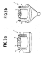
- eine Schrägansicht der Gegenstände der
Figur 2 und - Figur 4:
- eine Detailansicht eines erfindungsgemäß ausgerüsteten Schienenfahrzeugs, wobei ein Wagen mit einem erfindungsgemäßen Geräteteil mit einem Wagen mit einem herkömmlichen UIC-Geräteteil verbunden ist.
- FIG. 1:
- a rail vehicle with an electrical system according to the invention in a schematic representation,
- FIG. 2:
- a plan view of an inventively used device part (a) and complementary plug part (b),
- FIG. 3:
- an oblique view of the objects of Figure 2 and
- FIG. 4:
- a detailed view of an inventively equipped rail vehicle, wherein a carriage is connected to a device part according to the invention with a car with a conventional UIC device part.
In der Figur 1 erkennt man ein Schienenfahrzeug 1 mit drei miteinander verbundenen Wagen 2, wobei jeder Wagen von Stromversorgungsleitungen 3 und Datenleitungen 3 von einem Wagenende zum anderen Wagenende durchspannt ist. Die Stromversorgungsleitungen und Datenleitungen sind in dieser schematischen Darstellung nicht separat wiedergegeben. Die Stromversorgungsleitungen 3 und Datenleitungen 3 verschiedener Wagen sind über die Kabelverbindung 4 miteinander verbunden. Jede Kabelverbindung 4 weist an gegenüberliegenden Enden jeweils ein Steckerteil 6 auf. Jeweils ein Stekkerteil 6 einer Kabelverbindung 4 ist in ein Geräteteil 5 einander gegenüberliegender Wagenenden eingesteckt.In Figure 1 can be seen a rail vehicle 1 with three interconnected
Der Figur 2 sowie einer vergleichenden Betrachtung der Figurenteile 2a und 2b entnimmt man, dass das Steckerteil 6 einen im Wesentlichen hohlzylinderförmigen Führungsring 7 und das Geräteteil 5 eine zum Führungsring 7 komplementäre Führungsausnehmung 8 aufweist. Das Steckerteil 6 weist außerhalb des Führungsrings 7 und hierzu beabstandet ein sich parallel zum Führungsring 7 erstreckendes Satellitensteckelement 9 auf. Das Geräteteil 5 weist ein zum Satellitensteckelement 9 komplementäres Satellitengeräteelement 10 auf. Hierzu wird ergänzend auf die Schrägansicht der Figur 3 verwiesen. Man erkennt aus einer Betrachtung beider Figuren des Weiteren, dass das Geräteteil 5 einen Isolierkörper 14 aufweist, in welchen elektrische Kontaktbuchsen 15 eingebettet sind. Das Steckerteil 6 weist ebenfalls einen Isolierkörper 16 auf, wobei jedoch Kontaktstifte 17 über diesen Isolierkörper 16 herausragen. In analoger Weise sind die Satellitensteckerelemente 9 und Satellitengeräteelemente 10 aufgebaut, wobei im Falle der Satellitensteckerelemente 9 im Wesentlichen bohnenförmige Führungsringe eingerichtet sind. Selbstverständlich sind gegenüber der dargestellten Weise das Satellitensteckelement 9 und das Satellitengeräteelement 10 in Bezug auf die dargestellten Ausführungsformen gegeneinander vertauschbar, ohne dass die Funktion hierdurch verändert wird. Man erkennt, dass jedes Satellitensteckelement 9 zwei Satellitensteckkontakte 11 und jedes Satellitengeräteelement 10 zwei Satellitengerätekontakte 12 aufweist, wobei die Satellitensteckkontakte 11 und die Satellitengerätekontakte 12 zueinander komplementäre Satellitenkontaktpaare bilden. Zumindest ein Satellitenkontaktpaar ist als optisches Kontaktpaar ausgebildet. Die beiden Satellitensteckelemente 9 sind bezogen auf die Mittelachse des Führungsrings 7 einander gegenüberliegend. Die Satellitengeräteelemente 10 sind in komplementärer Weise im Rahmen des Geräteteils 5 eingerichtet. FIG. 2 as well as a comparative examination of the figure parts 2a and 2b shows that the
Der Figur 4 ist eine Verbindung zwischen zwei Wagen eines Schienenfahrzeugs entnehmbar, wobei einer der beiden Wagen (rechtsseitig) ein herkömmliches UIC-Geräteteil aufweist. Aufgrund der geometrischen Ausbildung, wie in den Figuren 2 und 3 dargestellt, kann das rechtsseitige Steckerteil 6 der Kabelverbindung 4 in das herkömmliche UIC-Geräteteil 5 des rechten Wagens 2 eingesteckt werden. Beide Wagen 2 weisen jeweils einen Zentralprozessor 13 auf. Nach der Herstellung der Kabelverbindung 4 prüft der Zentralprozessor 13 des linksseitigen Wagens, ob über die Datenleitung 3 der Kabelverbindung 4 eine Kommunikation mit dem Zentralprozessor 13 des rechtsseitigen Wagens möglich ist. In der Darstellung der Figur 4 erfolgt ein solcher Datenaustausch nicht, da die Datenleitung 3, welche im Rahmen eines Satellitensteckelements 9 eingerichtet ist, mangels Satellitengeräteelement 10 an dem herkömmlichen UIC-Geräteteil kein Satellitenkontaktpaar bildet. Hierauf wird das Betriebsprogramm des linksseitigen Zentralprozessors 13 auf Datenkommunikation über herkömmliche Leitungen einer üblichen UIC-Steckverbindung umgeschaltet und der linksseitige erfindungsgemäß ausgestattete Wagen 2 ist abwärtskompatibel mit dem herkömmlichen rechtsseitigen Wagen 2 datentechnisch verbunden.FIG. 4 shows a connection between two carriages of a rail vehicle, wherein one of the two carriages (on the right side) has a conventional UIC device part. Due to the geometric design, as in the figures 2 3 and 3, the right-
Insbesondere bei Einsatz "gemischter" Schienenfahrzeuge, i.e. mit Wagen, die herkömmliche UIC-Geräteteile 5 aufweisen, und Wagen, die erfindungsgemäße Geräteteile aufweisen, wird es sich empfehlen, Schutzkappen bzw. Schutzstopfen für nicht kontaktierte Satellitensteckelemente 9 bzw. Satellitengeräteelemente 10 vorzusehen. Dies verhindert eine Verschmutzung elektrischer Kontakte und insbesondere der empfindlichen optischen Kontakte. Alternativ zu einfachen Schutzkappen bzw. Schutzstopfen können auch im Zuge der Kontaktierung sich zurückziehende Schutzelemente eingerichtet sein. Dem Fachmann sind solche Konstruktionen aus anderen Zusammenhängen wohl bekannt. Ansonsten kann eine erfindungsgemäß einsetzte Steckverbindung alle mechanischen Merkmale einer herkömmlichen UIC-Verbindung aufweisen, insbesondere auch Schnappdeckel und Hebelverriegelung im Rahmen eines Geräteteils 5.In particular, when using "mixed" rail vehicles, ie with cars that have conventional
- 11
- Schienenfahrzeugtrack vehicle
- 22
- Wagendare
- 33
- Stromversorgungsleitung, DatenleitungPower supply line, data line
- 44
- Kabelverbindungcable connection
- 55
- Geräteteilequipment part
- 66
- Steckerverbindungplug connection
- 77
- Führungsringguide ring
- 88th
- Führungsausnehmungguide recess
- 99
- SatellitensteckelementSatellite plug element
- 1010
- SatellitengeräteelementSatellite equipment element
- 1111
- SatellitensteckkontaktSatellite plug contact
- 1212
- SatellitengerätekontaktSatellite appliances Contact
- 1313
- Zentralprozessorcentral processor
- 1414
- Isolierkörperinsulator
- 1515
- KontaktbuchsenContact jacks
- 1616
- Isolierkörperinsulator
- 1717
- Kontaktstiftecontact pins
Claims (6)
dadurch gekennzeichnet,
dass das Steckerteil (6) außerhalb des Führungsrings (7) und hierzu beabstandet ein sich parallel zum Führungsring (7) erstreckendes Satellitensteckelement (9) aufweist, und dass das Geräteteil 5 ein zum Satellitensteckelement (9) komplementäres Satellitengeräteelement (10) aufweist, wobei das Satellitensteckelement (9) zumindest einen Satellitensteckkontakt (11) und das Satellitengeräteelement (10) zumindest einen Satellitengerätekontakt (12) aufweist, wobei der Satellitensteckkontakt (11) und der Satellitengerätekontakt (12) als zueinander komplementäres Satellitenkontaktpaar ausgebildet sind.Electrical system for a rail vehicle (1) with at least two interconnected carriages (2), each carriage being spanned by power supply lines (3) and / or data lines (3) from one end of the car to the other end of the car, the power supply lines (3) and / or data lines (3) of different cars via a cable connection (4) are interconnected, wherein the cable connection (4) at least one plug part (6) and a plug part (6) complementary device part (5), wherein the plug part (6) has a essentially hollow-cylindrical guide ring (7) and the device part (5) has a guide recess (8) complementary to the guide ring (7),
characterized,
in that the plug part (6) has, outside the guide ring (7) and spaced therefrom, a satellite plug element (9) extending parallel to the guide ring (7), and in that the device part 5 has a satellite device element (10) complementary to the satellite plug element (9) Satellite plug-in element (9) at least one satellite plug contact (11) and the satellite device element (10) at least one satellite device contact (12), wherein the satellite plug contact (11) and the satellite device contact (12) are designed as complementary satellite contact pair.
Applications Claiming Priority (1)
| Application Number | Priority Date | Filing Date | Title |
|---|---|---|---|
| DE200520000594 DE202005000594U1 (en) | 2005-01-19 | 2005-01-19 | Electrical system for a rail vehicle |
Publications (2)
| Publication Number | Publication Date |
|---|---|
| EP1684385A2 true EP1684385A2 (en) | 2006-07-26 |
| EP1684385A3 EP1684385A3 (en) | 2009-11-04 |
Family
ID=34429103
Family Applications (1)
| Application Number | Title | Priority Date | Filing Date |
|---|---|---|---|
| EP06090004A Withdrawn EP1684385A3 (en) | 2005-01-19 | 2006-01-11 | Electric system for railway car |
Country Status (2)
| Country | Link |
|---|---|
| EP (1) | EP1684385A3 (en) |
| DE (1) | DE202005000594U1 (en) |
Cited By (1)
| Publication number | Priority date | Publication date | Assignee | Title |
|---|---|---|---|---|
| CN106476818A (en) * | 2016-10-28 | 2017-03-08 | 中车北京二七车辆有限公司 | A kind of Railway Refrigerated Transport container transporting device |
Families Citing this family (2)
| Publication number | Priority date | Publication date | Assignee | Title |
|---|---|---|---|---|
| DE102008054349A1 (en) * | 2008-11-03 | 2010-05-06 | Wabco Gmbh | Control arrangement for a trailer, trailer and adapter |
| CN104742989A (en) * | 2015-04-21 | 2015-07-01 | 南通市恒达机械制造有限公司 | Novel combined factory conveying vehicle |
Citations (6)
| Publication number | Priority date | Publication date | Assignee | Title |
|---|---|---|---|---|
| US4017136A (en) * | 1975-08-25 | 1977-04-12 | Power Parts Company | Permanent tri-headed jumper cable for locomotives |
| DE29618000U1 (en) * | 1996-10-07 | 1996-12-12 | Jaeger Erich Gmbh & Co Kg | socket |
| US20020098718A1 (en) * | 2001-01-22 | 2002-07-25 | Harmon Darren L. | Nosebox with interchangeable connector assemblies for tractors and trailers |
| WO2003030309A1 (en) * | 2001-10-02 | 2003-04-10 | Reese Products, Inc. | Power distribution apparatus for a vehicle equipped for trailer towing |
| EP1302381A1 (en) * | 2001-10-16 | 2003-04-16 | SCHARFENBERGKUPPLUNG GmbH & Co. KG | Electrical connector |
| US20040207514A1 (en) * | 1995-11-09 | 2004-10-21 | Alan Lesesky | System, apparatus and methods for data communication between vehicle and remote data communication terminal, between portions of vehicle and other portions of vehicle, between two or more vehicles, and between vehicle and communications network |
-
2005
- 2005-01-19 DE DE200520000594 patent/DE202005000594U1/en not_active Expired - Lifetime
-
2006
- 2006-01-11 EP EP06090004A patent/EP1684385A3/en not_active Withdrawn
Patent Citations (6)
| Publication number | Priority date | Publication date | Assignee | Title |
|---|---|---|---|---|
| US4017136A (en) * | 1975-08-25 | 1977-04-12 | Power Parts Company | Permanent tri-headed jumper cable for locomotives |
| US20040207514A1 (en) * | 1995-11-09 | 2004-10-21 | Alan Lesesky | System, apparatus and methods for data communication between vehicle and remote data communication terminal, between portions of vehicle and other portions of vehicle, between two or more vehicles, and between vehicle and communications network |
| DE29618000U1 (en) * | 1996-10-07 | 1996-12-12 | Jaeger Erich Gmbh & Co Kg | socket |
| US20020098718A1 (en) * | 2001-01-22 | 2002-07-25 | Harmon Darren L. | Nosebox with interchangeable connector assemblies for tractors and trailers |
| WO2003030309A1 (en) * | 2001-10-02 | 2003-04-10 | Reese Products, Inc. | Power distribution apparatus for a vehicle equipped for trailer towing |
| EP1302381A1 (en) * | 2001-10-16 | 2003-04-16 | SCHARFENBERGKUPPLUNG GmbH & Co. KG | Electrical connector |
Cited By (2)
| Publication number | Priority date | Publication date | Assignee | Title |
|---|---|---|---|---|
| CN106476818A (en) * | 2016-10-28 | 2017-03-08 | 中车北京二七车辆有限公司 | A kind of Railway Refrigerated Transport container transporting device |
| CN106476818B (en) * | 2016-10-28 | 2018-10-16 | 中车北京二七车辆有限公司 | A kind of Railway Refrigerated Transport container transporting device |
Also Published As
| Publication number | Publication date |
|---|---|
| DE202005000594U1 (en) | 2005-04-07 |
| EP1684385A3 (en) | 2009-11-04 |
Similar Documents
| Publication | Publication Date | Title |
|---|---|---|
| DE69826202T2 (en) | The cable connector assembly | |
| DE102008038641A1 (en) | Device for producing a compound | |
| EP2847829A1 (en) | Electrical series terminal | |
| DE202008014989U1 (en) | Device for producing a compound | |
| DE202017102886U1 (en) | Adapter plug for a charging system for charging an electric vehicle | |
| EP1684385A2 (en) | Electric system for railway car | |
| DE202013006512U1 (en) | Electric traction coupling | |
| WO2014095205A2 (en) | Plug-and-socket connection for rail-bound vehicles | |
| DE102018009478A1 (en) | Connector arrangement | |
| EP3607614A1 (en) | Method for implementing a wiring on a matrix of conductor connection devices, and series terminal assembly | |
| DE102021113979A1 (en) | measurement module system | |
| DE1802457C3 (en) | Plug-in device | |
| EP1523790A1 (en) | Plug connector with additional contact device in particular for data transfer | |
| DE102017103996A1 (en) | Connector module with bridging function | |
| EP1414117B1 (en) | Connector arrangement having two different plugs matching two different types of receptacles | |
| DE3537944C2 (en) | ||
| DE3127246C2 (en) | ||
| EP1328422B1 (en) | Node point on a data bus for a motor vehicle | |
| DE2418634A1 (en) | Plug-in connector with actuator and intermediate element - has tension released spring latch locking intermediate element and socket | |
| DE102010039957B4 (en) | Separator bushing assemblies and separator adapters with a carrier plate and one or more separator bushings of the separator bushing assemblies mounted therein | |
| DE10213990B4 (en) | Electrical connection or connection terminal | |
| DE2706447A1 (en) | CONNECTOR FOR A CLOSED BUSBAR ARRANGEMENT | |
| EP0286697B1 (en) | Disconnectable multipole plug connection for the transfer of electrical currents, for instance for use in motor cars | |
| DE102022121178A1 (en) | Switch connector system and device cabling | |
| DE102022123031A1 (en) | Connector assembly and circuit board mounting system for a circuit breaker |
Legal Events
| Date | Code | Title | Description |
|---|---|---|---|
| PUAI | Public reference made under article 153(3) epc to a published international application that has entered the european phase |
Free format text: ORIGINAL CODE: 0009012 |
|
| AK | Designated contracting states |
Kind code of ref document: A2 Designated state(s): AT BE BG CH CY CZ DE DK EE ES FI FR GB GR HU IE IS IT LI LT LU LV MC NL PL PT RO SE SI SK TR |
|
| AX | Request for extension of the european patent |
Extension state: AL BA HR MK YU |
|
| PUAL | Search report despatched |
Free format text: ORIGINAL CODE: 0009013 |
|
| AK | Designated contracting states |
Kind code of ref document: A3 Designated state(s): AT BE BG CH CY CZ DE DK EE ES FI FR GB GR HU IE IS IT LI LT LU LV MC NL PL PT RO SE SI SK TR |
|
| AX | Request for extension of the european patent |
Extension state: AL BA HR MK YU |
|
| AKX | Designation fees paid | ||
| STAA | Information on the status of an ep patent application or granted ep patent |
Free format text: STATUS: THE APPLICATION IS DEEMED TO BE WITHDRAWN |
|
| 18D | Application deemed to be withdrawn |
Effective date: 20100505 |
|
| REG | Reference to a national code |
Ref country code: DE Ref legal event code: 8566 |