EP1684045A2 - Plastic modular radiator element for building heating systems - Google Patents
Plastic modular radiator element for building heating systems Download PDFInfo
- Publication number
- EP1684045A2 EP1684045A2 EP05106995A EP05106995A EP1684045A2 EP 1684045 A2 EP1684045 A2 EP 1684045A2 EP 05106995 A EP05106995 A EP 05106995A EP 05106995 A EP05106995 A EP 05106995A EP 1684045 A2 EP1684045 A2 EP 1684045A2
- Authority
- EP
- European Patent Office
- Prior art keywords
- sleeve
- modular element
- plate
- duct
- modular
- Prior art date
- Legal status (The legal status is an assumption and is not a legal conclusion. Google has not performed a legal analysis and makes no representation as to the accuracy of the status listed.)
- Granted
Links
- 239000004033 plastic Substances 0.000 title claims abstract description 15
- 238000010438 heat treatment Methods 0.000 title claims abstract description 9
- 239000012530 fluid Substances 0.000 claims abstract description 25
- 238000004891 communication Methods 0.000 claims abstract description 7
- 239000000463 material Substances 0.000 claims description 9
- 239000004743 Polypropylene Substances 0.000 claims description 2
- 230000010339 dilation Effects 0.000 claims description 2
- 238000001125 extrusion Methods 0.000 claims description 2
- 229920000728 polyester Polymers 0.000 claims description 2
- -1 polypropylene Polymers 0.000 claims description 2
- 229920001155 polypropylene Polymers 0.000 claims description 2
- 229920005606 polypropylene copolymer Polymers 0.000 claims 2
- 239000000835 fiber Substances 0.000 claims 1
- 238000001746 injection moulding Methods 0.000 claims 1
- 238000009434 installation Methods 0.000 abstract description 2
- 238000009827 uniform distribution Methods 0.000 abstract 1
- 239000002994 raw material Substances 0.000 description 8
- 229910000831 Steel Inorganic materials 0.000 description 4
- 239000004411 aluminium Substances 0.000 description 4
- 229910052782 aluminium Inorganic materials 0.000 description 4
- XAGFODPZIPBFFR-UHFFFAOYSA-N aluminium Chemical compound [Al] XAGFODPZIPBFFR-UHFFFAOYSA-N 0.000 description 4
- 238000004519 manufacturing process Methods 0.000 description 4
- 239000007769 metal material Substances 0.000 description 4
- 239000010959 steel Substances 0.000 description 4
- 238000005304 joining Methods 0.000 description 3
- 238000000465 moulding Methods 0.000 description 3
- 229910001018 Cast iron Inorganic materials 0.000 description 2
- 230000008878 coupling Effects 0.000 description 2
- 238000010168 coupling process Methods 0.000 description 2
- 238000005859 coupling reaction Methods 0.000 description 2
- 238000009826 distribution Methods 0.000 description 2
- 244000045947 parasite Species 0.000 description 2
- 229920005630 polypropylene random copolymer Polymers 0.000 description 2
- 238000003466 welding Methods 0.000 description 2
- 229910000838 Al alloy Inorganic materials 0.000 description 1
- RYGMFSIKBFXOCR-UHFFFAOYSA-N Copper Chemical compound [Cu] RYGMFSIKBFXOCR-UHFFFAOYSA-N 0.000 description 1
- 239000004809 Teflon Substances 0.000 description 1
- 229920006362 Teflon® Polymers 0.000 description 1
- 238000010521 absorption reaction Methods 0.000 description 1
- 239000003795 chemical substances by application Substances 0.000 description 1
- 239000003086 colorant Substances 0.000 description 1
- 229910052802 copper Inorganic materials 0.000 description 1
- 239000010949 copper Substances 0.000 description 1
- 238000010586 diagram Methods 0.000 description 1
- 238000005516 engineering process Methods 0.000 description 1
- 238000002347 injection Methods 0.000 description 1
- 239000007924 injection Substances 0.000 description 1
- JEIPFZHSYJVQDO-UHFFFAOYSA-N iron(III) oxide Inorganic materials O=[Fe]O[Fe]=O JEIPFZHSYJVQDO-UHFFFAOYSA-N 0.000 description 1
- 238000003754 machining Methods 0.000 description 1
- 230000008018 melting Effects 0.000 description 1
- 238000002844 melting Methods 0.000 description 1
- 239000002184 metal Substances 0.000 description 1
- 229910052751 metal Inorganic materials 0.000 description 1
- 150000002739 metals Chemical class 0.000 description 1
- 238000012986 modification Methods 0.000 description 1
- 230000004048 modification Effects 0.000 description 1
- 238000010422 painting Methods 0.000 description 1
- 239000012783 reinforcing fiber Substances 0.000 description 1
- 230000035939 shock Effects 0.000 description 1
- 238000004381 surface treatment Methods 0.000 description 1
- 238000011282 treatment Methods 0.000 description 1
Images

Classifications
-
- F—MECHANICAL ENGINEERING; LIGHTING; HEATING; WEAPONS; BLASTING
- F28—HEAT EXCHANGE IN GENERAL
- F28D—HEAT-EXCHANGE APPARATUS, NOT PROVIDED FOR IN ANOTHER SUBCLASS, IN WHICH THE HEAT-EXCHANGE MEDIA DO NOT COME INTO DIRECT CONTACT
- F28D1/00—Heat-exchange apparatus having stationary conduit assemblies for one heat-exchange medium only, the media being in contact with different sides of the conduit wall, in which the other heat-exchange medium is a large body of fluid, e.g. domestic or motor car radiators
- F28D1/02—Heat-exchange apparatus having stationary conduit assemblies for one heat-exchange medium only, the media being in contact with different sides of the conduit wall, in which the other heat-exchange medium is a large body of fluid, e.g. domestic or motor car radiators with heat-exchange conduits immersed in the body of fluid
- F28D1/04—Heat-exchange apparatus having stationary conduit assemblies for one heat-exchange medium only, the media being in contact with different sides of the conduit wall, in which the other heat-exchange medium is a large body of fluid, e.g. domestic or motor car radiators with heat-exchange conduits immersed in the body of fluid with tubular conduits
- F28D1/053—Heat-exchange apparatus having stationary conduit assemblies for one heat-exchange medium only, the media being in contact with different sides of the conduit wall, in which the other heat-exchange medium is a large body of fluid, e.g. domestic or motor car radiators with heat-exchange conduits immersed in the body of fluid with tubular conduits the conduits being straight
- F28D1/05308—Assemblies of conduits connected side by side or with individual headers, e.g. section type radiators
-
- F—MECHANICAL ENGINEERING; LIGHTING; HEATING; WEAPONS; BLASTING
- F28—HEAT EXCHANGE IN GENERAL
- F28F—DETAILS OF HEAT-EXCHANGE AND HEAT-TRANSFER APPARATUS, OF GENERAL APPLICATION
- F28F21/00—Constructions of heat-exchange apparatus characterised by the selection of particular materials
- F28F21/06—Constructions of heat-exchange apparatus characterised by the selection of particular materials of plastics material
- F28F21/062—Constructions of heat-exchange apparatus characterised by the selection of particular materials of plastics material the heat-exchange apparatus employing tubular conduits
- F28F21/063—Constructions of heat-exchange apparatus characterised by the selection of particular materials of plastics material the heat-exchange apparatus employing tubular conduits for domestic or space-heating systems
-
- F—MECHANICAL ENGINEERING; LIGHTING; HEATING; WEAPONS; BLASTING
- F28—HEAT EXCHANGE IN GENERAL
- F28F—DETAILS OF HEAT-EXCHANGE AND HEAT-TRANSFER APPARATUS, OF GENERAL APPLICATION
- F28F9/00—Casings; Header boxes; Auxiliary supports for elements; Auxiliary members within casings
- F28F9/02—Header boxes; End plates
- F28F9/0219—Arrangements for sealing end plates into casing or header box; Header box sub-elements
- F28F9/0221—Header boxes or end plates formed by stacked elements
Definitions
- the present invention relates to the building heating systems sector in general, and particularly concerns a plastic modular radiator element complete with a heat-carrier fluid flow distributor element.
- heat emitter is used, in accordance with the standard UNI EN 442, to mean a device having the purpose of releasing heat so as to obtain specific temperature conditions in a building
- radiationator is used, again in accordance with the standard EN 442, to mean a heat emitter that emits heat by natural convection and irradiation, manufactured and sold in modular elements of identical dimensions that can be assembled in "batteries” to form an assembly providing the desired total thermal output.
- modular radiator elements are now generally made by molding and/or extrusion of various metal materials (steel, aluminium alloys, extruded aluminium, cast iron, copper) and consist of tubular vertical elements (hereinafter called “branches") of variable number that converge above and below on a coupling, in the form of a horizontal portion of duct, also called a "hub".
- branches tubular vertical elements
- Several modular elements are combined together to form a battery (or radiator), defining a hydraulic circuit consisting of a top hub and a bottom hub (resulting from the connection of the couplings of the various modular elements) that are in communication with each other by means of a plurality of vertical columns or ducts or branches.
- the resulting radiator battery is connected to a heat-carrier fluid distribution system by means of specific inlet and outlet flow control valves, through which the fluid is delivered to a first hub in the battery, respectively called top or bottom hub, consisting of a horizontal duct from which the vertical branches of the radiator depart, the latter providing the connection to a second hub, respectively called bottom or top hub.
- the radiator elements are hydraulically connected in parallel by the top and bottom hub and, given the manufacturing technologies used (which depend on the metal materials involved), the cross sections of the radiator branches - added together and placed in relation to the fluid flow rates through them - are comparable with the cross section of the hub. That is why any pressure drop of the fluid moving through a branch is much the same as the pressure drop through the hub. This gives rise to uneven heat-carrier fluid distributions that negatively affect the operation and thermal output of the radiator.
- the object of the present invention is to provide a radiator for building heating systems characterized particularly by a light weight, adaptability to the space in which it is designed to operate, strength, insensitivity to stray and/or parasite currents (which tend to corrode the inside of the radiators) and to any agents that might corrode its outside surface.
- a further object of the present invention is to provide a radiator of the above-mentioned type that is less complex and more cost-effective to manufacture and assemble in batteries.
- Another object of the present invention is to provide a radiator of the above-mentioned type in which the fluid flow is evenly distributed so as to result in uniform pressure drops and equal thermal outputs for each element or module.
- the numeral 1 is used to indicate the heat-carrier fluid distributor for a modular building heating radiator element consisting of a generically four-sided plate 2 and, more precisely, substantially rectangular, delimited by a perimetrical edge 3 orthogonal to the plate.
- said edge 3 has four nozzles 4 with holes 5 in the middle (figure 4).
- a through sleeve 6 is also connected perpendicularly to the plate 2, projecting from both sides thereof.
- the sleeve 6 is situated about halfway along the edge opposite the nozzles 4 and terminates on one side with a tapered, narrower portion 7, the outer diameter of which substantially coincides with the inner diameter of the sleeve 6 before said tapering.
- the plate 2 can be composed of two plate portions, coupled and molded so as to define four channels 8 which, after joining the two plate portions, give rise to a corresponding number of tubular ducts that place the sleeve 6 in communication with the nozzles 4.
- the plate 2 with the edge 3, the nozzles 4 and the sleeve 6 are molded in a single piece.
- the distributor can consist of the edge 3, acting as a supporting frame, the nozzles 4 and the sleeve 6 connected to the edge 3 and communicating with the nozzle 4 via radial ducts 8, all molded in a single piece.
- the modular radiator element consists, in the example of an embodiment illustrated in figure 7, of four parallel radiator branches 9 and two heat-carrier fluid distributors attached to the respective ends thereof.
- Said branches are lengths of piping that, being connected at the top and bottom to the distributors by means of the nozzles 4, place the top and bottom sleeves 6 in communication with one another.
- figure 8 shows the hydraulic circuit of a battery of nine modules or elements.
- a heat-carrier fluid inlet A which in this figure is situated at the bottom, and a corresponding outlet L are shown therein.
- the various vertical lengths represent the single modules, while the two horizontal sections (AI and LT) represent the top and bottom hubs.
- the letters indicate the top and bottom joints between each module and the two hubs.
- each of the hydraulic circuits of figure 8 (A-L, A-B-M-L, A-B-C-N-M-L, and so on) connecting the fluid inlet A to the outlet L carries the same fluid flow rate, thereby ensuring an even thermal output from the single radiator elements.
- a particularly preferred embodiment for achieving the objects of the invention involves making the modular element out of a plastic material, e.g. polypropylene, such as a polypropylene random copolymer (PP-R), with or without reinforcing fibers, or a polyester.
- the plastic material used is characterized by a thermal conductivity of at least 0.15 W/m°K and a thermal dilation coefficient of no more than 3.5.10 -5 °K -1 , can be injection molded or extruded with a reflecting surface finish, can be heat-welded, has a useful working temperature of at least 90°C, and can withstand a working pressure of at least 3.5 bar.
- joining the various component parts of a modular element, and joining several modules together to form a radiator can be done economically and with a limited energy absorption by heat-welding the plastic using Teflon-coated aluminium calibrators or templates of suitable dimensions heated to the melting temperature of the plastic raw material.
- Teflon-coated aluminium calibrators or templates of suitable dimensions heated to the melting temperature of the plastic raw material it is sufficient to insert the parts to weld (for spigot and socket joints) or rest them (for end-to-end joints) against the calibrators for a suitable time and then apply a certain pressure. Then it is sufficient to simply extract (spigot and socket joints) or separate (end-to-end joints) the parts and place them in contact with one another for an established time interval under an adequate contact pressure, as a function of the material being used, in order to achieve a permanent joint.
- the raw material used makes it unnecessary to provide for any surface treatments to protect either the inside (against stray and/or parasite currents) or the outside (against rust or magnetic pollution).
- lighter-weight elements approximately 60% lighter than steel or aluminium and 80% lighter than cast iron
- the hardness and stiffness of the raw material used in this invention are lower than those of the metal materials normally used, thus reducing any damage caused by accidental shocks.
- the raw material used in this invention also adapts to the use of all the standard accessories for completing a battery of radiators.
- the raw material identified drastically reduces the noise levels due to the fluid flowing in poorly-dimensioned systems, especially in the case of radiators made of extruded and die-cast aluminium.
Landscapes
- Engineering & Computer Science (AREA)
- Physics & Mathematics (AREA)
- Thermal Sciences (AREA)
- Mechanical Engineering (AREA)
- General Engineering & Computer Science (AREA)
- Steam Or Hot-Water Central Heating Systems (AREA)
- Domestic Hot-Water Supply Systems And Details Of Heating Systems (AREA)
- Central Heating Systems (AREA)
- Instantaneous Water Boilers, Portable Hot-Water Supply Apparatuses, And Control Of Portable Hot-Water Supply Apparatuses (AREA)
- Heat-Exchange Devices With Radiators And Conduit Assemblies (AREA)
- Moulds For Moulding Plastics Or The Like (AREA)
- Injection Moulding Of Plastics Or The Like (AREA)
Abstract
Description
- The present invention relates to the building heating systems sector in general, and particularly concerns a plastic modular radiator element complete with a heat-carrier fluid flow distributor element.
- In the present description, the term "heat emitter" is used, in accordance with the standard UNI EN 442, to mean a device having the purpose of releasing heat so as to obtain specific temperature conditions in a building, and the term "radiator" is used, again in accordance with the standard EN 442, to mean a heat emitter that emits heat by natural convection and irradiation, manufactured and sold in modular elements of identical dimensions that can be assembled in "batteries" to form an assembly providing the desired total thermal output.
- It is common knowledge that modular radiator elements are now generally made by molding and/or extrusion of various metal materials (steel, aluminium alloys, extruded aluminium, cast iron, copper) and consist of tubular vertical elements (hereinafter called "branches") of variable number that converge above and below on a coupling, in the form of a horizontal portion of duct, also called a "hub". Several modular elements are combined together to form a battery (or radiator), defining a hydraulic circuit consisting of a top hub and a bottom hub (resulting from the connection of the couplings of the various modular elements) that are in communication with each other by means of a plurality of vertical columns or ducts or branches.
- The resulting radiator battery is connected to a heat-carrier fluid distribution system by means of specific inlet and outlet flow control valves, through which the fluid is delivered to a first hub in the battery, respectively called top or bottom hub, consisting of a horizontal duct from which the vertical branches of the radiator depart, the latter providing the connection to a second hub, respectively called bottom or top hub. The radiator elements are hydraulically connected in parallel by the top and bottom hub and, given the manufacturing technologies used (which depend on the metal materials involved), the cross sections of the radiator branches - added together and placed in relation to the fluid flow rates through them - are comparable with the cross section of the hub. That is why any pressure drop of the fluid moving through a branch is much the same as the pressure drop through the hub. This gives rise to uneven heat-carrier fluid distributions that negatively affect the operation and thermal output of the radiator.
- The object of the present invention is to provide a radiator for building heating systems characterized particularly by a light weight, adaptability to the space in which it is designed to operate, strength, insensitivity to stray and/or parasite currents (which tend to corrode the inside of the radiators) and to any agents that might corrode its outside surface.
- A further object of the present invention is to provide a radiator of the above-mentioned type that is less complex and more cost-effective to manufacture and assemble in batteries.
- Another object of the present invention is to provide a radiator of the above-mentioned type in which the fluid flow is evenly distributed so as to result in uniform pressure drops and equal thermal outputs for each element or module.
- These objects are achieved by the modular element for a building heating radiator according to the present invention, the essential features of which are set forth in
claim 1. - Other characteristics and advantages of the plastic modular radiator element for heating systems according to the present invention will appear more clearly from the following description of an embodiment, given as a nonlimiting example with reference to the attached drawings, wherein:
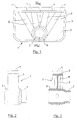
- figure 1 shows a front view of a heat-carrier fluid distributor element for a modular radiator element according to the present invention,
- figure 2 shows a side view of the distributor element of figure 1,
- figure 3 shows a cross section taken along the line III-III of figure 1,
- figure 4 shows a top view of the modular element of figure 1,
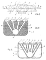
- figure 5 is a longitudinal section taken along the line V-V of figure 4,
- figure 6 is a longitudinal section taken along the line VI-VI of figure 4,
- figure 7 shows a front view of a modular radiator element with a heat-carrier fluid distributor according to the present invention,
- figure 8 shows a diagram of the hydraulic circuit for a radiator.
- With reference to figures 1-6, the
numeral 1 is used to indicate the heat-carrier fluid distributor for a modular building heating radiator element consisting of a generically four-sided plate 2 and, more precisely, substantially rectangular, delimited by aperimetrical edge 3 orthogonal to the plate. Along one of the two longer sides of theplate 2, saidedge 3 has fournozzles 4 withholes 5 in the middle (figure 4). A throughsleeve 6 is also connected perpendicularly to theplate 2, projecting from both sides thereof. Thesleeve 6 is situated about halfway along the edge opposite thenozzles 4 and terminates on one side with a tapered,narrower portion 7, the outer diameter of which substantially coincides with the inner diameter of thesleeve 6 before said tapering. - In particular, the
plate 2 can be composed of two plate portions, coupled and molded so as to define fourchannels 8 which, after joining the two plate portions, give rise to a corresponding number of tubular ducts that place thesleeve 6 in communication with thenozzles 4. Preferably, theplate 2 with theedge 3, thenozzles 4 and thesleeve 6 are molded in a single piece. In an embodiment of the invention, the distributor can consist of theedge 3, acting as a supporting frame, thenozzles 4 and thesleeve 6 connected to theedge 3 and communicating with thenozzle 4 viaradial ducts 8, all molded in a single piece. - The modular radiator element consists, in the example of an embodiment illustrated in figure 7, of four parallel radiator branches 9 and two heat-carrier fluid distributors attached to the respective ends thereof. Said branches are lengths of piping that, being connected at the top and bottom to the distributors by means of the
nozzles 4, place the top andbottom sleeves 6 in communication with one another. - Several modular elements are joined together to form a radiator by inserting the
tapered portion 7 of thesleeve 6, in thesleeve 6 of the next modular element, in this way also assembling the top and bottom hubs of the radiator battery. - Connecting several modular elements together gives rise to radiator batteries with different thermal outputs; figure 8 shows the hydraulic circuit of a battery of nine modules or elements. A heat-carrier fluid inlet A, which in this figure is situated at the bottom, and a corresponding outlet L are shown therein. The various vertical lengths represent the single modules, while the two horizontal sections (AI and LT) represent the top and bottom hubs. The letters indicate the top and bottom joints between each module and the two hubs.
- As it flows through a length of piping, a fluid undergoes a pressure drop that is inversely proportional to the fifth power of the pipe diameter, so a reduction of the pipe diameter results in an increase of the pressure drop. Moreover, there are pressure drops proportional to the kinetic energy of the fluid due to the fluid entering and exiting through the hubs and branches. To make the heat-carrier fluid flow smoothly through the radiator, given the configuration of the hydraulic circuit of figure 8, it is essential to increase the pressure drops in the fluid flowing through the branches to a sufficient degree so that the pressure drop through the hubs is negligible, or at least substantially lower.
- In the above-described heat-carrier fluid distributor, the diameter of the four
channels 8 departing from thesleeve 6, which is approximately 30 mm, is reduced to 6 mm (as opposed to the approximately 23 mm obtainable in steel radiators), so the pressure drops are considerably increased. Thus, for the same total flow rate, each of the hydraulic circuits of figure 8 (A-L, A-B-M-L, A-B-C-N-M-L, and so on) connecting the fluid inlet A to the outlet L carries the same fluid flow rate, thereby ensuring an even thermal output from the single radiator elements. - A particularly preferred embodiment for achieving the objects of the invention involves making the modular element out of a plastic material, e.g. polypropylene, such as a polypropylene random copolymer (PP-R), with or without reinforcing fibers, or a polyester. The plastic material used is characterized by a thermal conductivity of at least 0.15 W/m°K and a thermal dilation coefficient of no more than 3.5.10-5°K-1, can be injection molded or extruded with a reflecting surface finish, can be heat-welded, has a useful working temperature of at least 90°C, and can withstand a working pressure of at least 3.5 bar.
- Using this raw material enables the industrialization of a single-stage production of both the distributor and the columns. In fact, said operation would pose considerable machining difficulties if steel were used, in terms of the welding of the branches to the distributor. If the molding of other metal materials were attempted, on the other hand, this would considerably increase the costs, due to the need to raise the molding pressures to achieve branches with a narrower diameter than those of the known art.
- In addition, joining the various component parts of a modular element, and joining several modules together to form a radiator can be done economically and with a limited energy absorption by heat-welding the plastic using Teflon-coated aluminium calibrators or templates of suitable dimensions heated to the melting temperature of the plastic raw material. In fact, it is sufficient to insert the parts to weld (for spigot and socket joints) or rest them (for end-to-end joints) against the calibrators for a suitable time and then apply a certain pressure. Then it is sufficient to simply extract (spigot and socket joints) or separate (end-to-end joints) the parts and place them in contact with one another for an established time interval under an adequate contact pressure, as a function of the material being used, in order to achieve a permanent joint.
- Moreover, the raw material used makes it unnecessary to provide for any surface treatments to protect either the inside (against stray and/or parasite currents) or the outside (against rust or magnetic pollution).
- No painting treatment is needed because the required color can be obtained already in the previously-specified raw material. The wide range of colors that it is possible to choose also enables the design to be better customized.
- Using a raw material of lower specific weight as compared to the various metals conventionally used enables the manufacture of lighter-weight elements (approximately 60% lighter than steel or aluminium and 80% lighter than cast iron), which makes their transportation and installation more straightforward and economical.
- The hardness and stiffness of the raw material used in this invention are lower than those of the metal materials normally used, thus reducing any damage caused by accidental shocks.
- The raw material used in this invention also adapts to the use of all the standard accessories for completing a battery of radiators.
- Finally, the raw material identified drastically reduces the noise levels due to the fluid flowing in poorly-dimensioned systems, especially in the case of radiators made of extruded and die-cast aluminium.
- There may be variants of and/or modifications to the plastic modular radiator element for room heating systems according to the present invention without departing from the scope of the present invention.
Claims (11)
- Modular radiator element for building heating systems characterized in that it is made of a plastic material.
- Modular element as in claim 1, characterized in that said plastic material has a thermal conductivity of at least 0.15 W/m°K, a thermal dilation coefficient of no more than 3.5 · 10-5°K-1, is suitable for injection molding or extrusion, and has a reflecting, heat-weldable surface finish.
- Modular element as in claims 1 or 2, characterized in that said plastic material has a useful working temperature of at least 90°C and can withstand a working pressure of at least 3.5 bar.
- Modular element as in any of the claims 1, 2 or 3, characterized in that the plastic material is a polypropylene or a polyester.
- Modular element as in claim 4, characterized in that said plastic material is reinforced with fibers.
- Modular element as in claim 5, characterized in that said plastic material is a random polypropylene copolymer (PP-R).
- Modular element as in any of the previous claims, comprising two horizontal sleeves (6) and at least one vertical duct or branch (9) connected at either end to said sleeves so as to enable the passage through said duct of an heat-carrier fluid, entering through one of said sleeves and departing through the other, and in which at least one duct branches radially from each sleeve so as to place said sleeve in communication with said at least one vertical branch.
- Modular element as in claim 7, wherein each sleeve (6) extends orthogonally and integrally through a plate (2), said plate being composed of two plate portions that are joined and molded together so as to define on each of them at least one channel (8) that, after the two plate portions have been joined together, constitutes at least one tubular duct placing said sleeve in communication with said at least one vertical branch (9).
- Modular element as in claim 7, wherein each sleeve (6) extends orthogonally and integrally through a plate (2), at least one duct (8) being obtained within said plate so as to extend radially from said sleeve to place said sleeve in communication with said at least one vertical branch.
- Modular element as in claim 7, wherein there is at least one nozzle (4) on one side of said plate (2) that communicates with said at least one tubular duct (8) formed within said plate and with a corresponding vertical branch (9) to which it is connected.
- Modular element as in claim 7 or 8, wherein said at least one tubular duct (8) has a substantially narrower cross-section than that of the corresponding vertical duct (9).
Priority Applications (1)
| Application Number | Priority Date | Filing Date | Title |
|---|---|---|---|
| PL05106995T PL1684045T3 (en) | 2004-12-06 | 2005-07-28 | Plastic modular radiator element for building heating systems |
Applications Claiming Priority (1)
| Application Number | Priority Date | Filing Date | Title |
|---|---|---|---|
| IT000251A ITFI20040251A1 (en) | 2004-12-06 | 2004-12-06 | MODULAR RADIATOR ELEMENT IN PLASTIC MATERIAL FOR ENVIRONMENTAL HEATING SYSTEMS WITH FLUID FLUID DISTRIBUTOR ELEMENT OF DISTRIBUTOR |
Publications (3)
| Publication Number | Publication Date |
|---|---|
| EP1684045A2 true EP1684045A2 (en) | 2006-07-26 |
| EP1684045A3 EP1684045A3 (en) | 2007-09-19 |
| EP1684045B1 EP1684045B1 (en) | 2011-06-15 |
Family
ID=36477223
Family Applications (1)
| Application Number | Title | Priority Date | Filing Date |
|---|---|---|---|
| EP05106995A Expired - Lifetime EP1684045B1 (en) | 2004-12-06 | 2005-07-28 | Plastic modular radiator element for building heating systems |
Country Status (6)
| Country | Link |
|---|---|
| EP (1) | EP1684045B1 (en) |
| AT (1) | ATE513175T1 (en) |
| ES (1) | ES2368068T3 (en) |
| IT (1) | ITFI20040251A1 (en) |
| PL (1) | PL1684045T3 (en) |
| PT (1) | PT1684045E (en) |
Cited By (5)
| Publication number | Priority date | Publication date | Assignee | Title |
|---|---|---|---|---|
| WO2008015719A1 (en) * | 2006-08-02 | 2008-02-07 | Teknotherm S.R.L. | Structure of radiator for heating |
| EP2236968A2 (en) | 2007-11-05 | 2010-10-06 | Provost, Helmut Werner | Modular heat exchange system for use in central heat exchange installations in buildings |
| WO2010131272A1 (en) * | 2009-05-12 | 2010-11-18 | Stiliac S.P.A. | Distribution and collection head for heating radiators with pipes, and manufacturing method |
| CN102954627A (en) * | 2012-11-21 | 2013-03-06 | 三花控股集团有限公司 | Heat exchanger |
| WO2019202442A1 (en) * | 2018-04-17 | 2019-10-24 | Zehnder Group International Ag | Pipe grid, pipe grid assembly and method for producing same |
Citations (3)
| Publication number | Priority date | Publication date | Assignee | Title |
|---|---|---|---|---|
| DE1454435A1 (en) | 1964-09-24 | 1969-02-13 | Bernhard Kirsch | Heating element for the construction of plastic heating elements |
| CH510245A (en) | 1968-11-28 | 1971-07-15 | Veba Chemie Ag | Articulated tubular radiator made of thermoplastic material |
| FR2134147A1 (en) | 1971-04-22 | 1972-12-08 | Ideal Standard |
Family Cites Families (3)
| Publication number | Priority date | Publication date | Assignee | Title |
|---|---|---|---|---|
| FR1349270A (en) * | 1962-11-13 | 1964-01-17 | Forges & Ateliers Du Plat De G | Improvements to steel tube radiators for central heating and the like |
| US5582241A (en) * | 1994-02-14 | 1996-12-10 | Yoho; Robert W. | Heat exchanging fins with fluid circulation lines therewithin |
| DE50011836D1 (en) * | 1999-02-16 | 2006-01-19 | Arnold Schludermann | Heat exchanger and plug |
-
2004
- 2004-12-06 IT IT000251A patent/ITFI20040251A1/en unknown
-
2005
- 2005-07-28 EP EP05106995A patent/EP1684045B1/en not_active Expired - Lifetime
- 2005-07-28 ES ES05106995T patent/ES2368068T3/en not_active Expired - Lifetime
- 2005-07-28 PL PL05106995T patent/PL1684045T3/en unknown
- 2005-07-28 PT PT05106995T patent/PT1684045E/en unknown
- 2005-07-28 AT AT05106995T patent/ATE513175T1/en not_active IP Right Cessation
Patent Citations (3)
| Publication number | Priority date | Publication date | Assignee | Title |
|---|---|---|---|---|
| DE1454435A1 (en) | 1964-09-24 | 1969-02-13 | Bernhard Kirsch | Heating element for the construction of plastic heating elements |
| CH510245A (en) | 1968-11-28 | 1971-07-15 | Veba Chemie Ag | Articulated tubular radiator made of thermoplastic material |
| FR2134147A1 (en) | 1971-04-22 | 1972-12-08 | Ideal Standard |
Cited By (9)
| Publication number | Priority date | Publication date | Assignee | Title |
|---|---|---|---|---|
| WO2008015719A1 (en) * | 2006-08-02 | 2008-02-07 | Teknotherm S.R.L. | Structure of radiator for heating |
| EP2236968A2 (en) | 2007-11-05 | 2010-10-06 | Provost, Helmut Werner | Modular heat exchange system for use in central heat exchange installations in buildings |
| WO2010131272A1 (en) * | 2009-05-12 | 2010-11-18 | Stiliac S.P.A. | Distribution and collection head for heating radiators with pipes, and manufacturing method |
| CN102428337A (en) * | 2009-05-12 | 2012-04-25 | 斯蒂莱卡股份有限公司 | Distributing and collecting head for radiator with tubes and method of manufacture |
| EA019174B1 (en) * | 2009-05-12 | 2014-01-30 | Стилиак С.П.А. | Distribution and collection head for heating radiators with pipes, and manufacturing method |
| CN102428337B (en) * | 2009-05-12 | 2014-10-22 | 斯蒂莱卡股份有限公司 | Distribution and collection head for heating radiators with pipes, and manufacturing method |
| CN102954627A (en) * | 2012-11-21 | 2013-03-06 | 三花控股集团有限公司 | Heat exchanger |
| CN102954627B (en) * | 2012-11-21 | 2015-12-23 | 杭州三花微通道换热器有限公司 | Heat exchanger |
| WO2019202442A1 (en) * | 2018-04-17 | 2019-10-24 | Zehnder Group International Ag | Pipe grid, pipe grid assembly and method for producing same |
Also Published As
| Publication number | Publication date |
|---|---|
| EP1684045A3 (en) | 2007-09-19 |
| PL1684045T3 (en) | 2011-11-30 |
| ITFI20040251A1 (en) | 2005-03-06 |
| EP1684045B1 (en) | 2011-06-15 |
| ES2368068T3 (en) | 2011-11-14 |
| ATE513175T1 (en) | 2011-07-15 |
| PT1684045E (en) | 2011-09-22 |
Similar Documents
| Publication | Publication Date | Title |
|---|---|---|
| US6988539B2 (en) | Heat exchanger | |
| AU594234B2 (en) | Convector/radiator construction | |
| EP1684045B1 (en) | Plastic modular radiator element for building heating systems | |
| US20150107535A1 (en) | Heat exchanger, set and method for forming the same | |
| KR20120092642A (en) | Exhaust gas heat exchanger | |
| US20020179297A1 (en) | Heat exchanger | |
| JP6560645B2 (en) | Piping system using piping joint | |
| ES2359484T3 (en) | RADIATOR WITH PARTIAL LOAD FUNCTION. | |
| CN1425120A (en) | Water heater comprising a plate heat exchanger and a storage vessel for heated water | |
| IE50686B1 (en) | Space heater | |
| US6935361B2 (en) | Pipe, piping system, radiant heating system, and kit | |
| RS20080528A (en) | Structure of radiator for heating | |
| CN102460056A (en) | Pipe fitting and capillary network formed by pipe fittings | |
| CA2594420C (en) | Modular heat exchanger | |
| WO1993012389A1 (en) | Quick operating heat exchanger device | |
| CZ294207B6 (en) | Tubular heating body | |
| EP2435766A2 (en) | Water heater | |
| WO2008055910A2 (en) | A plate, couplable to an edge of an opening afforded in a tubular element, and a method for constraining the plate to the edge | |
| KR100423003B1 (en) | An Assembly Type Support For Cooling Tower | |
| US20080283046A1 (en) | Solar collector having integral structure | |
| JPH0425589Y2 (en) | ||
| US4300628A (en) | Heat exchanger assembly | |
| US4881312A (en) | Method for manufacturing a fitting for a heat exchanger | |
| CZ2007526A3 (en) | Universal partition, particularly for radiators with lower connection to heating system | |
| CN104279888A (en) | Heat exchangers |
Legal Events
| Date | Code | Title | Description |
|---|---|---|---|
| PUAI | Public reference made under article 153(3) epc to a published international application that has entered the european phase |
Free format text: ORIGINAL CODE: 0009012 |
|
| AK | Designated contracting states |
Kind code of ref document: A2 Designated state(s): AT BE BG CH CY CZ DE DK EE ES FI FR GB GR HU IE IS IT LI LT LU LV MC NL PL PT RO SE SI SK TR |
|
| AX | Request for extension of the european patent |
Extension state: AL BA HR MK YU |
|
| PUAL | Search report despatched |
Free format text: ORIGINAL CODE: 0009013 |
|
| AK | Designated contracting states |
Kind code of ref document: A3 Designated state(s): AT BE BG CH CY CZ DE DK EE ES FI FR GB GR HU IE IS IT LI LT LU LV MC NL PL PT RO SE SI SK TR |
|
| AX | Request for extension of the european patent |
Extension state: AL BA HR MK YU |
|
| RIC1 | Information provided on ipc code assigned before grant |
Ipc: F28F 9/02 20060101ALI20070813BHEP Ipc: F28F 21/06 20060101AFI20060612BHEP Ipc: F28F 9/26 20060101ALI20070813BHEP |
|
| 17P | Request for examination filed |
Effective date: 20080318 |
|
| 17Q | First examination report despatched |
Effective date: 20080417 |
|
| AKX | Designation fees paid |
Designated state(s): AT BE BG CH CY CZ DE DK EE ES FI FR GB GR HU IE IS IT LI LT LU LV MC NL PL PT RO SE SI SK TR |
|
| GRAP | Despatch of communication of intention to grant a patent |
Free format text: ORIGINAL CODE: EPIDOSNIGR1 |
|
| GRAS | Grant fee paid |
Free format text: ORIGINAL CODE: EPIDOSNIGR3 |
|
| GRAA | (expected) grant |
Free format text: ORIGINAL CODE: 0009210 |
|
| AK | Designated contracting states |
Kind code of ref document: B1 Designated state(s): AT BE BG CH CY CZ DE DK EE ES FI FR GB GR HU IE IS IT LI LT LU LV MC NL PL PT RO SE SI SK TR |
|
| REG | Reference to a national code |
Ref country code: GB Ref legal event code: FG4D Ref country code: CH Ref legal event code: EP |
|
| REG | Reference to a national code |
Ref country code: IE Ref legal event code: FG4D |
|
| REG | Reference to a national code |
Ref country code: DE Ref legal event code: R096 Ref document number: 602005028498 Country of ref document: DE Effective date: 20110728 |
|
| REG | Reference to a national code |
Ref country code: RO Ref legal event code: EPE |
|
| REG | Reference to a national code |
Ref country code: NL Ref legal event code: T3 |
|
| REG | Reference to a national code |
Ref country code: PT Ref legal event code: SC4A Free format text: AVAILABILITY OF NATIONAL TRANSLATION Effective date: 20110914 |
|
| PG25 | Lapsed in a contracting state [announced via postgrant information from national office to epo] |
Ref country code: SE Free format text: LAPSE BECAUSE OF FAILURE TO SUBMIT A TRANSLATION OF THE DESCRIPTION OR TO PAY THE FEE WITHIN THE PRESCRIBED TIME-LIMIT Effective date: 20110615 Ref country code: LT Free format text: LAPSE BECAUSE OF FAILURE TO SUBMIT A TRANSLATION OF THE DESCRIPTION OR TO PAY THE FEE WITHIN THE PRESCRIBED TIME-LIMIT Effective date: 20110615 |
|
| REG | Reference to a national code |
Ref country code: ES Ref legal event code: FG2A Ref document number: 2368068 Country of ref document: ES Kind code of ref document: T3 Effective date: 20111114 |
|
| PG25 | Lapsed in a contracting state [announced via postgrant information from national office to epo] |
Ref country code: FI Free format text: LAPSE BECAUSE OF FAILURE TO SUBMIT A TRANSLATION OF THE DESCRIPTION OR TO PAY THE FEE WITHIN THE PRESCRIBED TIME-LIMIT Effective date: 20110615 Ref country code: SI Free format text: LAPSE BECAUSE OF FAILURE TO SUBMIT A TRANSLATION OF THE DESCRIPTION OR TO PAY THE FEE WITHIN THE PRESCRIBED TIME-LIMIT Effective date: 20110615 Ref country code: AT Free format text: LAPSE BECAUSE OF FAILURE TO SUBMIT A TRANSLATION OF THE DESCRIPTION OR TO PAY THE FEE WITHIN THE PRESCRIBED TIME-LIMIT Effective date: 20110615 Ref country code: CY Free format text: LAPSE BECAUSE OF FAILURE TO SUBMIT A TRANSLATION OF THE DESCRIPTION OR TO PAY THE FEE WITHIN THE PRESCRIBED TIME-LIMIT Effective date: 20110615 Ref country code: GR Free format text: LAPSE BECAUSE OF FAILURE TO SUBMIT A TRANSLATION OF THE DESCRIPTION OR TO PAY THE FEE WITHIN THE PRESCRIBED TIME-LIMIT Effective date: 20110916 Ref country code: LV Free format text: LAPSE BECAUSE OF FAILURE TO SUBMIT A TRANSLATION OF THE DESCRIPTION OR TO PAY THE FEE WITHIN THE PRESCRIBED TIME-LIMIT Effective date: 20110615 |
|
| REG | Reference to a national code |
Ref country code: PL Ref legal event code: T3 |
|
| PG25 | Lapsed in a contracting state [announced via postgrant information from national office to epo] |
Ref country code: CZ Free format text: LAPSE BECAUSE OF FAILURE TO SUBMIT A TRANSLATION OF THE DESCRIPTION OR TO PAY THE FEE WITHIN THE PRESCRIBED TIME-LIMIT Effective date: 20110615 Ref country code: EE Free format text: LAPSE BECAUSE OF FAILURE TO SUBMIT A TRANSLATION OF THE DESCRIPTION OR TO PAY THE FEE WITHIN THE PRESCRIBED TIME-LIMIT Effective date: 20110615 Ref country code: IS Free format text: LAPSE BECAUSE OF FAILURE TO SUBMIT A TRANSLATION OF THE DESCRIPTION OR TO PAY THE FEE WITHIN THE PRESCRIBED TIME-LIMIT Effective date: 20111015 |
|
| PG25 | Lapsed in a contracting state [announced via postgrant information from national office to epo] |
Ref country code: SK Free format text: LAPSE BECAUSE OF FAILURE TO SUBMIT A TRANSLATION OF THE DESCRIPTION OR TO PAY THE FEE WITHIN THE PRESCRIBED TIME-LIMIT Effective date: 20110615 Ref country code: MC Free format text: LAPSE BECAUSE OF NON-PAYMENT OF DUE FEES Effective date: 20110731 |
|
| REG | Reference to a national code |
Ref country code: CH Ref legal event code: PL |
|
| PLBE | No opposition filed within time limit |
Free format text: ORIGINAL CODE: 0009261 |
|
| STAA | Information on the status of an ep patent application or granted ep patent |
Free format text: STATUS: NO OPPOSITION FILED WITHIN TIME LIMIT |
|
| REG | Reference to a national code |
Ref country code: IE Ref legal event code: MM4A |
|
| PG25 | Lapsed in a contracting state [announced via postgrant information from national office to epo] |
Ref country code: LI Free format text: LAPSE BECAUSE OF NON-PAYMENT OF DUE FEES Effective date: 20110731 Ref country code: CH Free format text: LAPSE BECAUSE OF NON-PAYMENT OF DUE FEES Effective date: 20110731 |
|
| 26N | No opposition filed |
Effective date: 20120316 |
|
| PG25 | Lapsed in a contracting state [announced via postgrant information from national office to epo] |
Ref country code: DK Free format text: LAPSE BECAUSE OF FAILURE TO SUBMIT A TRANSLATION OF THE DESCRIPTION OR TO PAY THE FEE WITHIN THE PRESCRIBED TIME-LIMIT Effective date: 20110615 |
|
| REG | Reference to a national code |
Ref country code: DE Ref legal event code: R097 Ref document number: 602005028498 Country of ref document: DE Effective date: 20120316 |
|
| PG25 | Lapsed in a contracting state [announced via postgrant information from national office to epo] |
Ref country code: IE Free format text: LAPSE BECAUSE OF NON-PAYMENT OF DUE FEES Effective date: 20110728 |
|
| PGFP | Annual fee paid to national office [announced via postgrant information from national office to epo] |
Ref country code: RO Payment date: 20120716 Year of fee payment: 8 |
|
| PGFP | Annual fee paid to national office [announced via postgrant information from national office to epo] |
Ref country code: PL Payment date: 20120712 Year of fee payment: 8 |
|
| PGFP | Annual fee paid to national office [announced via postgrant information from national office to epo] |
Ref country code: BE Payment date: 20120720 Year of fee payment: 8 Ref country code: FR Payment date: 20120806 Year of fee payment: 8 Ref country code: ES Payment date: 20120726 Year of fee payment: 8 |
|
| PGFP | Annual fee paid to national office [announced via postgrant information from national office to epo] |
Ref country code: PT Payment date: 20110914 Year of fee payment: 8 Ref country code: NL Payment date: 20120719 Year of fee payment: 8 |
|
| PG25 | Lapsed in a contracting state [announced via postgrant information from national office to epo] |
Ref country code: LU Free format text: LAPSE BECAUSE OF NON-PAYMENT OF DUE FEES Effective date: 20110728 |
|
| PG25 | Lapsed in a contracting state [announced via postgrant information from national office to epo] |
Ref country code: BG Free format text: LAPSE BECAUSE OF FAILURE TO SUBMIT A TRANSLATION OF THE DESCRIPTION OR TO PAY THE FEE WITHIN THE PRESCRIBED TIME-LIMIT Effective date: 20110915 |
|
| PG25 | Lapsed in a contracting state [announced via postgrant information from national office to epo] |
Ref country code: HU Free format text: LAPSE BECAUSE OF FAILURE TO SUBMIT A TRANSLATION OF THE DESCRIPTION OR TO PAY THE FEE WITHIN THE PRESCRIBED TIME-LIMIT Effective date: 20110615 |
|
| BERE | Be: lapsed |
Owner name: IACOPINI, LEANDRO Effective date: 20130731 Owner name: NESI, UMBERTO Effective date: 20130731 |
|
| REG | Reference to a national code |
Ref country code: PT Ref legal event code: MM4A Free format text: LAPSE DUE TO NON-PAYMENT OF FEES Effective date: 20140128 |
|
| REG | Reference to a national code |
Ref country code: NL Ref legal event code: V1 Effective date: 20140201 |
|
| REG | Reference to a national code |
Ref country code: FR Ref legal event code: ST Effective date: 20140331 |
|
| PG25 | Lapsed in a contracting state [announced via postgrant information from national office to epo] |
Ref country code: RO Free format text: LAPSE BECAUSE OF NON-PAYMENT OF DUE FEES Effective date: 20130728 Ref country code: BE Free format text: LAPSE BECAUSE OF NON-PAYMENT OF DUE FEES Effective date: 20130731 Ref country code: NL Free format text: LAPSE BECAUSE OF NON-PAYMENT OF DUE FEES Effective date: 20140201 |
|
| PG25 | Lapsed in a contracting state [announced via postgrant information from national office to epo] |
Ref country code: FR Free format text: LAPSE BECAUSE OF NON-PAYMENT OF DUE FEES Effective date: 20130731 |
|
| PGFP | Annual fee paid to national office [announced via postgrant information from national office to epo] |
Ref country code: TR Payment date: 20140124 Year of fee payment: 9 |
|
| PG25 | Lapsed in a contracting state [announced via postgrant information from national office to epo] |
Ref country code: PT Free format text: LAPSE BECAUSE OF NON-PAYMENT OF DUE FEES Effective date: 20140128 |
|
| REG | Reference to a national code |
Ref country code: ES Ref legal event code: FD2A Effective date: 20140908 |
|
| PGFP | Annual fee paid to national office [announced via postgrant information from national office to epo] |
Ref country code: DE Payment date: 20140730 Year of fee payment: 10 |
|
| REG | Reference to a national code |
Ref country code: PL Ref legal event code: LAPE |
|
| PG25 | Lapsed in a contracting state [announced via postgrant information from national office to epo] |
Ref country code: PL Free format text: LAPSE BECAUSE OF NON-PAYMENT OF DUE FEES Effective date: 20130728 Ref country code: ES Free format text: LAPSE BECAUSE OF NON-PAYMENT OF DUE FEES Effective date: 20130729 |
|
| PGFP | Annual fee paid to national office [announced via postgrant information from national office to epo] |
Ref country code: GB Payment date: 20140730 Year of fee payment: 10 |
|
| PGFP | Annual fee paid to national office [announced via postgrant information from national office to epo] |
Ref country code: IT Payment date: 20150715 Year of fee payment: 11 |
|
| REG | Reference to a national code |
Ref country code: DE Ref legal event code: R119 Ref document number: 602005028498 Country of ref document: DE |
|
| GBPC | Gb: european patent ceased through non-payment of renewal fee |
Effective date: 20150728 |
|
| PG25 | Lapsed in a contracting state [announced via postgrant information from national office to epo] |
Ref country code: DE Free format text: LAPSE BECAUSE OF NON-PAYMENT OF DUE FEES Effective date: 20160202 Ref country code: GB Free format text: LAPSE BECAUSE OF NON-PAYMENT OF DUE FEES Effective date: 20150728 |
|
| PG25 | Lapsed in a contracting state [announced via postgrant information from national office to epo] |
Ref country code: TR Free format text: LAPSE BECAUSE OF NON-PAYMENT OF DUE FEES Effective date: 20140728 Ref country code: IT Free format text: LAPSE BECAUSE OF NON-PAYMENT OF DUE FEES Effective date: 20160728 |