EP1683947A2 - Method to control starter/generator cooling fuel flow during engine starting - Google Patents
Method to control starter/generator cooling fuel flow during engine starting Download PDFInfo
- Publication number
- EP1683947A2 EP1683947A2 EP05256532A EP05256532A EP1683947A2 EP 1683947 A2 EP1683947 A2 EP 1683947A2 EP 05256532 A EP05256532 A EP 05256532A EP 05256532 A EP05256532 A EP 05256532A EP 1683947 A2 EP1683947 A2 EP 1683947A2
- Authority
- EP
- European Patent Office
- Prior art keywords
- fuel
- shutoff valve
- frttv
- seat
- shutoff
- Prior art date
- Legal status (The legal status is an assumption and is not a legal conclusion. Google has not performed a legal analysis and makes no representation as to the accuracy of the status listed.)
- Withdrawn
Links
Images

Classifications
-
- F—MECHANICAL ENGINEERING; LIGHTING; HEATING; WEAPONS; BLASTING
- F01—MACHINES OR ENGINES IN GENERAL; ENGINE PLANTS IN GENERAL; STEAM ENGINES
- F01P—COOLING OF MACHINES OR ENGINES IN GENERAL; COOLING OF INTERNAL-COMBUSTION ENGINES
- F01P3/00—Liquid cooling
- F01P3/20—Cooling circuits not specific to a single part of engine or machine
-
- F—MECHANICAL ENGINEERING; LIGHTING; HEATING; WEAPONS; BLASTING
- F01—MACHINES OR ENGINES IN GENERAL; ENGINE PLANTS IN GENERAL; STEAM ENGINES
- F01D—NON-POSITIVE DISPLACEMENT MACHINES OR ENGINES, e.g. STEAM TURBINES
- F01D25/00—Component parts, details, or accessories, not provided for in, or of interest apart from, other groups
- F01D25/08—Cooling; Heating; Heat-insulation
- F01D25/12—Cooling
-
- F—MECHANICAL ENGINEERING; LIGHTING; HEATING; WEAPONS; BLASTING
- F02—COMBUSTION ENGINES; HOT-GAS OR COMBUSTION-PRODUCT ENGINE PLANTS
- F02C—GAS-TURBINE PLANTS; AIR INTAKES FOR JET-PROPULSION PLANTS; CONTROLLING FUEL SUPPLY IN AIR-BREATHING JET-PROPULSION PLANTS
- F02C7/00—Features, components parts, details or accessories, not provided for in, or of interest apart form groups F02C1/00 - F02C6/00; Air intakes for jet-propulsion plants
- F02C7/12—Cooling of plants
- F02C7/16—Cooling of plants characterised by cooling medium
-
- F—MECHANICAL ENGINEERING; LIGHTING; HEATING; WEAPONS; BLASTING
- F02—COMBUSTION ENGINES; HOT-GAS OR COMBUSTION-PRODUCT ENGINE PLANTS
- F02C—GAS-TURBINE PLANTS; AIR INTAKES FOR JET-PROPULSION PLANTS; CONTROLLING FUEL SUPPLY IN AIR-BREATHING JET-PROPULSION PLANTS
- F02C7/00—Features, components parts, details or accessories, not provided for in, or of interest apart form groups F02C1/00 - F02C6/00; Air intakes for jet-propulsion plants
- F02C7/26—Starting; Ignition
- F02C7/268—Starting drives for the rotor, acting directly on the rotor of the gas turbine to be started
-
- F—MECHANICAL ENGINEERING; LIGHTING; HEATING; WEAPONS; BLASTING
- F02—COMBUSTION ENGINES; HOT-GAS OR COMBUSTION-PRODUCT ENGINE PLANTS
- F02C—GAS-TURBINE PLANTS; AIR INTAKES FOR JET-PROPULSION PLANTS; CONTROLLING FUEL SUPPLY IN AIR-BREATHING JET-PROPULSION PLANTS
- F02C9/00—Controlling gas-turbine plants; Controlling fuel supply in air- breathing jet-propulsion plants
- F02C9/26—Control of fuel supply
- F02C9/38—Control of fuel supply characterised by throttling and returning of fuel to sump
-
- F—MECHANICAL ENGINEERING; LIGHTING; HEATING; WEAPONS; BLASTING
- F02—COMBUSTION ENGINES; HOT-GAS OR COMBUSTION-PRODUCT ENGINE PLANTS
- F02N—STARTING OF COMBUSTION ENGINES; STARTING AIDS FOR SUCH ENGINES, NOT OTHERWISE PROVIDED FOR
- F02N11/00—Starting of engines by means of electric motors
- F02N11/04—Starting of engines by means of electric motors the motors being associated with current generators
-
- F—MECHANICAL ENGINEERING; LIGHTING; HEATING; WEAPONS; BLASTING
- F01—MACHINES OR ENGINES IN GENERAL; ENGINE PLANTS IN GENERAL; STEAM ENGINES
- F01P—COOLING OF MACHINES OR ENGINES IN GENERAL; COOLING OF INTERNAL-COMBUSTION ENGINES
- F01P3/00—Liquid cooling
- F01P2003/005—Liquid cooling the liquid being fuel
-
- F—MECHANICAL ENGINEERING; LIGHTING; HEATING; WEAPONS; BLASTING
- F02—COMBUSTION ENGINES; HOT-GAS OR COMBUSTION-PRODUCT ENGINE PLANTS
- F02M—SUPPLYING COMBUSTION ENGINES IN GENERAL WITH COMBUSTIBLE MIXTURES OR CONSTITUENTS THEREOF
- F02M37/00—Apparatus or systems for feeding liquid fuel from storage containers to carburettors or fuel-injection apparatus; Arrangements for purifying liquid fuel specially adapted for, or arranged on, internal-combustion engines
- F02M37/0011—Constructional details; Manufacturing or assembly of elements of fuel systems; Materials therefor
- F02M37/0023—Valves in the fuel supply and return system
-
- F—MECHANICAL ENGINEERING; LIGHTING; HEATING; WEAPONS; BLASTING
- F02—COMBUSTION ENGINES; HOT-GAS OR COMBUSTION-PRODUCT ENGINE PLANTS
- F02M—SUPPLYING COMBUSTION ENGINES IN GENERAL WITH COMBUSTIBLE MIXTURES OR CONSTITUENTS THEREOF
- F02M37/00—Apparatus or systems for feeding liquid fuel from storage containers to carburettors or fuel-injection apparatus; Arrangements for purifying liquid fuel specially adapted for, or arranged on, internal-combustion engines
- F02M37/0047—Layout or arrangement of systems for feeding fuel
- F02M37/0052—Details on the fuel return circuit; Arrangement of pressure regulators
-
- Y—GENERAL TAGGING OF NEW TECHNOLOGICAL DEVELOPMENTS; GENERAL TAGGING OF CROSS-SECTIONAL TECHNOLOGIES SPANNING OVER SEVERAL SECTIONS OF THE IPC; TECHNICAL SUBJECTS COVERED BY FORMER USPC CROSS-REFERENCE ART COLLECTIONS [XRACs] AND DIGESTS
- Y02—TECHNOLOGIES OR APPLICATIONS FOR MITIGATION OR ADAPTATION AGAINST CLIMATE CHANGE
- Y02T—CLIMATE CHANGE MITIGATION TECHNOLOGIES RELATED TO TRANSPORTATION
- Y02T50/00—Aeronautics or air transport
- Y02T50/60—Efficient propulsion technologies, e.g. for aircraft
Definitions
- the present invention relates to electric starter generators and, more particularly, to cooling an electric starter generator during engine start.
- S/G electric starter generators
- air turbine starters to start the engines.
- S/Gs can generate significant heat during start and need to be cooled.
- One way to cool S/Gs is to use fan flow, but if fan flow is not available (such as during a ground start), fuel may be used to provide cooling during start.
- An S/G cooling system must be able to control the fuel flow used for cooling.
- a solenoid valve is used during engine start.
- this can be relatively expensive, heavy, and can consume significant electrical power.
- the present invention provides a relatively simple way to automatically turn on and off the fuel to an S/G cooling system during engine start.
- the present invention takes advantage of a fuel pressure rise provided by an engine fuel boost pump during the period from engine start to engine idle conditions. This pressure rise is used to stroke a mechanical shutoff valve in a fuel return to tank valve (FRTTV), which shuts off the starter generator cooling fuel flow. This shutoff occurs automatically with no other external input from, for example, an engine controller (e.g., a Full-Authority Digital Electronic Control (FADEC)).
- FADEC Full-Authority Digital Electronic Control
- pressure switches may be used to inform the FADEC if fuel is flowing to the heat exchangers through the FRTTV.
- a check valve is also included that prevents back flow through the system in the event of an engine start with no aircraft pumps running. Significant cost, weight, and power savings, and FADEC/wiring harness simplifications may be seen as a result.
- a FRTTV for use in an electric S/G cooling system that includes an S/G fuel oil heat exchanger for cooling S/G oil during engine start.
- the FRRTV includes a housing having an inlet and an outlet in fluid communication with a fuel tank.
- a seat is positioned between the inlet and outlet. Fluid flowing from the inlet to the outlet in the FRTTV flows through the seat.
- a shutoff valve in the FRTTV is movable from a fuel flow position, with the shutoff valve away from the seat, to a fuel shutoff position, with the shutoff valve against the seat.
- the FRRTV also includes a signal pressure inlet that is connected to the shutoff valve. The signal pressure inlet is able to sense engine fuel pressure rise from an engine fuel boost pump. As the engine fuel pressure rises, the shutoff valve is urged from the fuel flow position to the fuel shutoff position.
- a method is disclosed to automatically turn on and off fuel to an S/G cooling system using a FRTTV coupled to an engine fuel boost pump during engine start.
- the method includes aircraft boost pump fuel flowing into the FRTTV and opening the FRRTV based on the aircraft boost pump fuel pressure rise.
- the FRTTV also senses fuel discharge pressure rise from engine fuel boost pump.
- the FRRTV may close based on the sensed fuel pressure rise.
- FIG. 1 is a schematic diagram of a heat exchanger fuel system
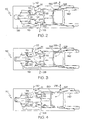
- FIG. 2 is a cross-sectional view of an FRTTV in a closed position in engine shutdown mode
- FIG. 3 is a cross-sectional view showing the FRTTV in an open or flowing position during engine start mode
- FIG. 4 is a cross-sectional view showing the FRTTV in a closed or shutoff position during engine run mode.
- FIG. 1 is a schematic diagram of a heat exchanger fuel system 100 for cooling oil from an electric starter/generator (S/G) used to start an aircraft engine.
- the heat exchanger fuel system 100 includes a S/G fuel oil heat exchanger that receives aircraft boost flow 102 from an aircraft boost pump (not shown) and a fuel return to tank valve (FRTTV) 112.
- S/G electric starter/generator
- FRTTV fuel return to tank valve
- the S/G fuel oil heat exchanger 106 is used to cool the S/G (not shown).
- the principles of heat exchangers are well known and need not be discussed in detail.
- Hot S/G oil 150 from the electric S/G enters an inlet 152 of the heat exchanger.
- the S/G oil heat exchanger 106 heat is transferred to the fuel flow 104a, cooling the S/G oil where the cool S/G oil 154 exits at an outlet 156 and returns to the starter/generators. While the S/G fuel oil heat exchanger 106 shown in the figure cools two S/Gs, more or less may be used.
- the FRTTV 112 includes a check valve 114 and a shutoff valve 116.
- the check valve 114 is included so that in the event of, for example, an aircraft boost pump malfunction, reverse fuel flow is prevented.
- the check valve 114 architecture incorporates a 45 degree hard seat engaging a .563 diameter seat 122.
- the check valve 114 includes a 1.125 diameter piston with a Teflon cap seal. This piston area provides 17 pounds of force, which works against a 7.5 pound spring pre-load by spring 124.
- the check valve 114 is normally closed against the seat 122 until there is a pressure flow 110 to open it (as shown in FIG. 2).
- the piston architecture allows the check valve 114 to have much greater force margin than what is normally achieved in a check valve.
- the check valve 114 may also include a guide stem with three flats. Having flats on the guide provides an area for contamination to escape, preventing the valve from binding. The Teflon cap seal prevents flow across the piston, preventing contamination from collecting in the diametrical clearance.
- the FRTTV 112 also includes the shutoff valve 116 that allows flow 126 to a fuel tank when engine speed is less than idle, and shuts flow to the fuel tank when the engine reaches idle speed.
- the shutoff valve 116 architecture has a 45 degree hard seat that engages the opposite side of the .563 diameter seat 122 than the check valve 114.
- a spring 130 is used to hold the shutoff valve 116 normally open with a 30 pound pre-load (as shown in FIG. 2).
- the depicted shutoff valve 116 includes a 1.313 diameter piston with a Teflon cap seal.
- the shutoff valve 116 also includes a guide diameter with four flats. Having flats on the guide provides an area for contamination to escape, preventing the valve from binding.
- the Teflon cap seal prevents flow across the piston, preventing contamination from collecting in the diametrical clearance.
- aircraft boost pump fuel flow 102 enters the heat exchanger fuel system 100 from an aircraft boost pump (not shown).
- the aircraft boost pump fuel flow 102 is then split, with a first portion of the flow 104a entering the S/G fuel oil heat exchanger 106 and a second portion of the flow 104b entering an engine main fuel boost centrifugal pump 108.
- the flow 104b travels through the S/G fuel oil heat exchanger 106, heat is transferred to the flow 104a from the hot S/G oil 150.
- Warm flow 110 exits the S/G fuel oil heat exchanger 106 and enters the FRTTV 112 at inlet 111.
- the flow pressure of the flow 104a entering the S/G fuel oil heat exchanger 106 may be approximately 20 PSIG and the flow 110 exiting the S/G fuel oil heat exchanger 106 may be approximately 17 PSIG (about a 3 psid inlet to outlet pressure drop).
- the flow 110 exiting the S/G fuel oil heat exchanger 106 enters the fuel return to tank valve (FRTTV) 112.
- the pressure pushes the check valve 114 open to the fuel flow position (the position shown in FIG. 1, see also FIG. 3).
- the backside of the check valve 114 is referenced to fuel tank return pressure 118, which is at atmospheric pressure.
- shutoff valve 116 With the check valve 114 open, fuel flows through the seat 122, through a metering orifice 120, and is then returned 126 to the fuel tank through an outlet 127.
- the shutoff valve 116 receives a signal pressure 128 from an aircraft centrifugal boost pump 108 at a signal pressure inlet 129 (see also FIG. 4).
- the signal pressure inlet 129 is separated from the cooling flow 110 by the piston and seal of the shutoff valve.
- the pressure 128 acts on the piston area of the shutoff valve 116 to create approximately 70 pounds of force, closing the shutoff valve 116 by pressing it against the seat 122 (the position shown in FIG. 1, see also FIG. 4). It should be noted that over 30 pounds of force margin is available to move the shutoff valve 116 either direction.
- the metering orifice 120 which is located downstream of the shutoff valve 116, is comprised of a .3125 diameter hole machined directly in the FRTTV 112 housing 138. It is sized to flow 3300 PPH fuel at 15 psid.
- the pressure in a chamber 132 bounded by the shutoff valve 116 and metering orifice 120 is routed within a passage 134 to two pressure switches 136a and 136b. These pressure switches 136a and 136b provide feedback to the FADEC on whether or not the FRTTV 112 is flowing.
- the pressure in this chamber 132 will be at 15 PSIG, and will close the electronic circuit in the two pressure switches 136a and 136b. If the shutoff valve 116 is closed, the pressure in this chamber 132 will fall to atmospheric tank pressure, and the circuit on the two pressure switches 136a and 136b will open. In the depicted embodiment, the two pressure switches 136a and 136b close the circuit at 8 PSIG, and open the circuit at 6 PSIG, but may be designed for any open or close pressure.
- FIG. 2 is a cross-sectional view showing one embodiment of the FRTTV 112.
- the FRTTV 112 architecture incorporates a single centerline valve assembly (single bore in housing 138).
- Both the check valve 114 and shutoff valve 116 are a sleeveless design, operating directly in the housing bore.
- the valves 114, 116 and seat 122 are fabricated from corrosion resistant steel, and the housing 138 is fabricated of aluminum alloy.
- the bore in the housing 138 has a heavy hard coat surface on the surfaces that contact the moving check valve 114 and the shutoff valve 116.
- the seat 122 is a unique design, serving as the seat for both the check valve 114 and the shutoff valve 116, the check valve 114 being on the inlet 111 side of the seat 122 and the shutoff valve 116 being on the outlet 129 side of the seat 122.
- the seat 122 is retained by the shutoff valve load spring 130, minimizing parts which simplifies the design.
- a single cover 140 fabricated of aluminum alloy retains the valve assembly.
- FIG. 2 shows the FRTTV 112 in a closed position in engine shutdown mode.
- this mode there is no flow 110 exiting the S/G fuel oil heat exchanger, so the spring 124 pushes the check valve 114 to its normally closed position against the seat 122, thereby preventing fluid flow through the seat 122.
- the shutoff valve 116 is in the normally open position being held there by spring 130.
- FIG. 3 is a cross-sectional view showing the FRTTV 112 in an open or flowing position during engine start mode. While the engine is started, flow 110 exiting the S/G fuel oil heat exchanger enters the FRTTV 112 at approximately 17 PSIG and applies pressure to the check valve face and latches the check valve 114 open away from the seat 122. The fluid is allowed to flow through the seat 122 and return 126 to the fuel tank. There is some signal pressure 128 coming from the aircraft centrifugal boost pump 108, but during engine startup the pressure rise is below 50 psid, which is not enough to overcome the spring 130 pressure to close the shutoff valve 116 against the seat 122.
- FIG. 4 is a cross-sectional view showing the FRTTV 112 in a closed or shutoff position during engine run mode.
- fuel or signal pressure 128 rises approximately 50 psid from the engine centrifugal boost pump 108. This pressure 128 acts on the piston area of the shutoff valve 116 to create approximately 70 pounds of force, closing the shutoff valve 116 against seat 122 preventing fluid flow.
Landscapes
- Engineering & Computer Science (AREA)
- Chemical & Material Sciences (AREA)
- Combustion & Propulsion (AREA)
- Mechanical Engineering (AREA)
- General Engineering & Computer Science (AREA)
- Fuel-Injection Apparatus (AREA)
- Electrical Control Of Air Or Fuel Supplied To Internal-Combustion Engine (AREA)
Abstract
Description
- The present invention relates to electric starter generators and, more particularly, to cooling an electric starter generator during engine start.
- Various aircraft are being designed to use electric starter generators (S/G) rather than air turbine starters to start the engines. These S/Gs can generate significant heat during start and need to be cooled. One way to cool S/Gs is to use fan flow, but if fan flow is not available (such as during a ground start), fuel may be used to provide cooling during start. An S/G cooling system must be able to control the fuel flow used for cooling. During engine start, one of the conventional ways to turn flow on and off in the S/G cooling system is through the use of a solenoid valve. However, this can be relatively expensive, heavy, and can consume significant electrical power.
- Accordingly, there is a need for a simple S/G cooling system that can provide S/G cooling during engine starting without the use of a solenoid valve. Furthermore, other desirable features and characteristics of the present invention will become apparent from the subsequent detailed description and the appended claims, taken in conjunction with the accompanying drawings and the foregoing technical field and background.
- The present invention provides a relatively simple way to automatically turn on and off the fuel to an S/G cooling system during engine start. The present invention takes advantage of a fuel pressure rise provided by an engine fuel boost pump during the period from engine start to engine idle conditions. This pressure rise is used to stroke a mechanical shutoff valve in a fuel return to tank valve (FRTTV), which shuts off the starter generator cooling fuel flow. This shutoff occurs automatically with no other external input from, for example, an engine controller (e.g., a Full-Authority Digital Electronic Control (FADEC)). Moreover, pressure switches may be used to inform the FADEC if fuel is flowing to the heat exchangers through the FRTTV. A check valve is also included that prevents back flow through the system in the event of an engine start with no aircraft pumps running. Significant cost, weight, and power savings, and FADEC/wiring harness simplifications may be seen as a result.
- In one embodiment, and by way of example only, a FRTTV is disclosed for use in an electric S/G cooling system that includes an S/G fuel oil heat exchanger for cooling S/G oil during engine start. The FRRTV includes a housing having an inlet and an outlet in fluid communication with a fuel tank. A seat is positioned between the inlet and outlet. Fluid flowing from the inlet to the outlet in the FRTTV flows through the seat. A shutoff valve in the FRTTV is movable from a fuel flow position, with the shutoff valve away from the seat, to a fuel shutoff position, with the shutoff valve against the seat. The FRRTV also includes a signal pressure inlet that is connected to the shutoff valve. The signal pressure inlet is able to sense engine fuel pressure rise from an engine fuel boost pump. As the engine fuel pressure rises, the shutoff valve is urged from the fuel flow position to the fuel shutoff position.
- In another embodiment, and by way of example only, a method is disclosed to automatically turn on and off fuel to an S/G cooling system using a FRTTV coupled to an engine fuel boost pump during engine start. The method includes aircraft boost pump fuel flowing into the FRTTV and opening the FRRTV based on the aircraft boost pump fuel pressure rise. The FRTTV also senses fuel discharge pressure rise from engine fuel boost pump. The FRRTV may close based on the sensed fuel pressure rise.
- Other independent features and advantages will become apparent from the following detailed description, taken in conjunction with the accompanying drawings which illustrate, by way of example, the principles of the invention.
In the Drawings; - The following drawings are illustrative of the particular embodiments of the invention and therefore do not limit its scope. They are presented to assist in providing a proper understanding of the invention. The drawings are not to scale and are intended for use in conjunction with the explanations in the following detailed descriptions. The present invention will hereinafter be described in conjunction with the appended drawings, wherein like reference numerals denote like elements, and;
- FIG. 1 is a schematic diagram of a heat exchanger fuel system;
- FIG. 2 is a cross-sectional view of an FRTTV in a closed position in engine shutdown mode;
- FIG. 3 is a cross-sectional view showing the FRTTV in an open or flowing position during engine start mode; and
- FIG. 4 is a cross-sectional view showing the FRTTV in a closed or shutoff position during engine run mode.
- The following detailed description of the invention is merely exemplary in nature and is not intended to limit the invention or the application and uses of the invention. Furthermore, there is no intention to be bound by any theory presented in the preceding background of the invention or the following detailed description of the invention.
- FIG. 1 is a schematic diagram of a heat
exchanger fuel system 100 for cooling oil from an electric starter/generator (S/G) used to start an aircraft engine. The heatexchanger fuel system 100 includes a S/G fuel oil heat exchanger that receivesaircraft boost flow 102 from an aircraft boost pump (not shown) and a fuel return to tank valve (FRTTV) 112. - The S/G fuel
oil heat exchanger 106 is used to cool the S/G (not shown). The principles of heat exchangers are well known and need not be discussed in detail. In the figure, Hot S/G oil 150 from the electric S/G enters aninlet 152 of the heat exchanger. As the S/G oil travels through the S/G fueloil heat exchanger 106, heat is transferred to thefuel flow 104a, cooling the S/G oil where the cool S/G oil 154 exits at anoutlet 156 and returns to the starter/generators. While the S/G fueloil heat exchanger 106 shown in the figure cools two S/Gs, more or less may be used. - The FRTTV 112 includes a
check valve 114 and ashutoff valve 116. Thecheck valve 114 is included so that in the event of, for example, an aircraft boost pump malfunction, reverse fuel flow is prevented. In the depicted embodiment, thecheck valve 114 architecture incorporates a 45 degree hard seat engaging a .563diameter seat 122. Thecheck valve 114 includes a 1.125 diameter piston with a Teflon cap seal. This piston area provides 17 pounds of force, which works against a 7.5 pound spring pre-load byspring 124. Thecheck valve 114 is normally closed against theseat 122 until there is apressure flow 110 to open it (as shown in FIG. 2). The piston architecture allows thecheck valve 114 to have much greater force margin than what is normally achieved in a check valve. Configuring thecheck valve 114 to latch in the open position minimizes pressure drop through the FRTTV 112. Thecheck valve 114 may also include a guide stem with three flats. Having flats on the guide provides an area for contamination to escape, preventing the valve from binding. The Teflon cap seal prevents flow across the piston, preventing contamination from collecting in the diametrical clearance. - The FRTTV 112 also includes the
shutoff valve 116 that allowsflow 126 to a fuel tank when engine speed is less than idle, and shuts flow to the fuel tank when the engine reaches idle speed. In the depicted embodiment, theshutoff valve 116 architecture has a 45 degree hard seat that engages the opposite side of the .563diameter seat 122 than thecheck valve 114. Aspring 130 is used to hold theshutoff valve 116 normally open with a 30 pound pre-load (as shown in FIG. 2). The depictedshutoff valve 116 includes a 1.313 diameter piston with a Teflon cap seal. Theshutoff valve 116 also includes a guide diameter with four flats. Having flats on the guide provides an area for contamination to escape, preventing the valve from binding. The Teflon cap seal prevents flow across the piston, preventing contamination from collecting in the diametrical clearance. - In use, aircraft boost
pump fuel flow 102 enters the heatexchanger fuel system 100 from an aircraft boost pump (not shown). The aircraft boostpump fuel flow 102 is then split, with a first portion of theflow 104a entering the S/G fueloil heat exchanger 106 and a second portion of theflow 104b entering an engine main fuel boostcentrifugal pump 108. As theflow 104b travels through the S/G fueloil heat exchanger 106, heat is transferred to theflow 104a from the hot S/G oil 150.Warm flow 110 exits the S/G fueloil heat exchanger 106 and enters theFRTTV 112 atinlet 111. The flow pressure of theflow 104a entering the S/G fueloil heat exchanger 106 may be approximately 20 PSIG and theflow 110 exiting the S/G fueloil heat exchanger 106 may be approximately 17 PSIG (about a 3 psid inlet to outlet pressure drop). Theflow 110 exiting the S/G fueloil heat exchanger 106 enters the fuel return to tank valve (FRTTV) 112. The pressure pushes thecheck valve 114 open to the fuel flow position (the position shown in FIG. 1, see also FIG. 3). The backside of thecheck valve 114 is referenced to fueltank return pressure 118, which is at atmospheric pressure. With thecheck valve 114 open, fuel flows through theseat 122, through ametering orifice 120, and is then returned 126 to the fuel tank through anoutlet 127. As the engine increases speed, fuel pressure rises across thiscentrifugal boost pump 108, theshutoff valve 116 receives asignal pressure 128 from an aircraftcentrifugal boost pump 108 at a signal pressure inlet 129 (see also FIG. 4). Thesignal pressure inlet 129 is separated from thecooling flow 110 by the piston and seal of the shutoff valve. At approximately 50 psid ofsignal pressure 128 rise, thepressure 128 acts on the piston area of theshutoff valve 116 to create approximately 70 pounds of force, closing theshutoff valve 116 by pressing it against the seat 122 (the position shown in FIG. 1, see also FIG. 4). It should be noted that over 30 pounds of force margin is available to move theshutoff valve 116 either direction. - In the depicted embodiment, the
metering orifice 120, which is located downstream of theshutoff valve 116, is comprised of a .3125 diameter hole machined directly in theFRTTV 112housing 138. It is sized to flow 3300 PPH fuel at 15 psid. The pressure in achamber 132 bounded by theshutoff valve 116 andmetering orifice 120 is routed within a passage 134 to twopressure switches FRTTV 112 is flowing. If theshutoff valve 116 is open and flowing, the pressure in thischamber 132 will be at 15 PSIG, and will close the electronic circuit in the twopressure switches shutoff valve 116 is closed, the pressure in thischamber 132 will fall to atmospheric tank pressure, and the circuit on the twopressure switches pressure switches - FIG. 2 is a cross-sectional view showing one embodiment of the
FRTTV 112. TheFRTTV 112 architecture incorporates a single centerline valve assembly (single bore in housing 138). Both thecheck valve 114 andshutoff valve 116 are a sleeveless design, operating directly in the housing bore. Thevalves seat 122 are fabricated from corrosion resistant steel, and thehousing 138 is fabricated of aluminum alloy. The bore in thehousing 138 has a heavy hard coat surface on the surfaces that contact the movingcheck valve 114 and theshutoff valve 116. Theseat 122 is a unique design, serving as the seat for both thecheck valve 114 and theshutoff valve 116, thecheck valve 114 being on theinlet 111 side of theseat 122 and theshutoff valve 116 being on theoutlet 129 side of theseat 122. Theseat 122 is retained by the shutoffvalve load spring 130, minimizing parts which simplifies the design. Asingle cover 140 fabricated of aluminum alloy retains the valve assembly. - FIG. 2 shows the
FRTTV 112 in a closed position in engine shutdown mode. In this mode, there is noflow 110 exiting the S/G fuel oil heat exchanger, so thespring 124 pushes thecheck valve 114 to its normally closed position against theseat 122, thereby preventing fluid flow through theseat 122. There is also nosignal pressure 128 coming from the enginecentrifugal boost pump 108, so theshutoff valve 116 is in the normally open position being held there byspring 130. - FIG. 3 is a cross-sectional view showing the
FRTTV 112 in an open or flowing position during engine start mode. While the engine is started, flow 110 exiting the S/G fuel oil heat exchanger enters theFRTTV 112 at approximately 17 PSIG and applies pressure to the check valve face and latches thecheck valve 114 open away from theseat 122. The fluid is allowed to flow through theseat 122 and return 126 to the fuel tank. There is somesignal pressure 128 coming from the aircraftcentrifugal boost pump 108, but during engine startup the pressure rise is below 50 psid, which is not enough to overcome thespring 130 pressure to close theshutoff valve 116 against theseat 122. - FIG. 4 is a cross-sectional view showing the
FRTTV 112 in a closed or shutoff position during engine run mode. As the engine speed increases, fuel orsignal pressure 128 rises approximately 50 psid from the enginecentrifugal boost pump 108. Thispressure 128 acts on the piston area of theshutoff valve 116 to create approximately 70 pounds of force, closing theshutoff valve 116 againstseat 122 preventing fluid flow. There is still flow 110 entering theFRTTV 112 keeping thecheck valve 114 open, but since theshutoff valve 116 is against the other side of theseat 122, fluid may not flow through the FRTTV. - While the invention has been described with reference to a preferred embodiment, it will be understood by those skilled in the art that various changes may be made and equivalents may be substituted for elements thereof without departing from the scope of the invention. In addition, many modifications may be made to adapt to a particular situation or material to the teachings of the invention without departing from the essential scope thereof. Therefore, it is intended that the invention not be limited to the particular embodiment disclosed as the best mode contemplated for carrying out this invention, but that the invention will include all embodiments falling within the scope of the appended claims.
Claims (4)
- A fuel return to tank valve (FRTTV) (112) for use in an electric starter/generator (S/G) cooling fuel flow system (100) having a S/G fuel oil heat exchanger (106) for cooling S/G oil during engine start, the FRTTV comprising:a housing (138) having an inlet (110), an outlet (126) and a seat (122) positioned between the inlet and the outlet, the inlet (110) being in fluid communication with the outlet through the seat;a shutoff valve (116) moveably positioned within the housing (138) configured to move between a fuel flow position away from the seat (122) and a fuel shutoff position against the seat (122); anda fuel signal pressure inlet (129) coupled to the shutoff valve (116), the fuel signal pressure inlet (129) being configured to sense fuel pressure rise from an engine fuel boost pump to urge the shutoff valve (116) from the fuel flow position to the fuel shutoff position.
- The FRTTV of claim 1, wherein the shutoff valve (116) is configured to move to the fuel shutoff position at approximately 50 psid of sensed fuel pressure rise.
- The FRTTV of claim 1, further comprising a shutoff valve spring (130) coupled to the shutoff valve (116), the shutoff valve spring being configured to urge the shutoff valve (116) away from the seat (122).
- The FRTTV of claim 3, wherein the shutoff valve spring (130) provides a 30 pound pre-load on the shutoff valve (116).
Applications Claiming Priority (1)
| Application Number | Priority Date | Filing Date | Title |
|---|---|---|---|
| US11/040,745 US7484522B2 (en) | 2004-10-19 | 2005-01-21 | Method to control starter/generator cooling fuel flow during engine starting |
Publications (2)
| Publication Number | Publication Date |
|---|---|
| EP1683947A2 true EP1683947A2 (en) | 2006-07-26 |
| EP1683947A3 EP1683947A3 (en) | 2007-04-18 |
Family
ID=36202436
Family Applications (1)
| Application Number | Title | Priority Date | Filing Date |
|---|---|---|---|
| EP05256532A Withdrawn EP1683947A3 (en) | 2005-01-21 | 2005-10-21 | Method to control starter/generator cooling fuel flow during engine starting |
Country Status (1)
| Country | Link |
|---|---|
| EP (1) | EP1683947A3 (en) |
Cited By (3)
| Publication number | Priority date | Publication date | Assignee | Title |
|---|---|---|---|---|
| US7793505B2 (en) | 2006-05-04 | 2010-09-14 | Pratt & Whitney Canada Corp | Gas turbine engine oil system operation |
| US20120160220A1 (en) * | 2010-12-21 | 2012-06-28 | Audi Ag | Device for ventilating and aerating a fuel tank |
| EP1983174A3 (en) * | 2007-04-17 | 2012-12-19 | Rolls-Royce plc | Apparatus and method of operating a gas turbine engine at start-up |
Families Citing this family (1)
| Publication number | Priority date | Publication date | Assignee | Title |
|---|---|---|---|---|
| RU2349790C2 (en) * | 2007-02-13 | 2009-03-20 | Открытое акционерное общество "АВТОВАЗ" | Method of starter-generator control and associated device |
Family Cites Families (2)
| Publication number | Priority date | Publication date | Assignee | Title |
|---|---|---|---|---|
| US5927064A (en) * | 1997-12-23 | 1999-07-27 | United Technologies Corporation | Start, shutoff and overspeed system for gas turbine engine |
| US6401446B1 (en) * | 2000-06-23 | 2002-06-11 | Hamilton Sundstrand Corporation | Valve apparatus for providing shutoff and overspeed protection in a gas turbine fuel system |
-
2005
- 2005-10-21 EP EP05256532A patent/EP1683947A3/en not_active Withdrawn
Cited By (3)
| Publication number | Priority date | Publication date | Assignee | Title |
|---|---|---|---|---|
| US7793505B2 (en) | 2006-05-04 | 2010-09-14 | Pratt & Whitney Canada Corp | Gas turbine engine oil system operation |
| EP1983174A3 (en) * | 2007-04-17 | 2012-12-19 | Rolls-Royce plc | Apparatus and method of operating a gas turbine engine at start-up |
| US20120160220A1 (en) * | 2010-12-21 | 2012-06-28 | Audi Ag | Device for ventilating and aerating a fuel tank |
Also Published As
| Publication number | Publication date |
|---|---|
| EP1683947A3 (en) | 2007-04-18 |
Similar Documents
| Publication | Publication Date | Title |
|---|---|---|
| US8196385B2 (en) | Turbomachine control system | |
| US9500135B2 (en) | Fuel feed circuit for an aeroengine having a high pressure pump system with two pumps | |
| US9702301B2 (en) | Fuel circuit for an aviation turbine engine, the circuit having a fuel pressure regulator valve | |
| CN100507240C (en) | Improved fuel delivery system | |
| US4829939A (en) | Cooling system for a turbo-compressor | |
| US8205597B2 (en) | Aircraft engine fuel supply | |
| EP1329617B1 (en) | Fluid flow system for a gas turbine engine | |
| US12158109B2 (en) | Aircraft turbine engine assembly comprising a passive valve for by-passing a fuel/oil heat exchanger | |
| US5110269A (en) | Gas turbine fuel pumping apparatus | |
| US8881870B2 (en) | Recirculation valve in an aircraft engine | |
| US6675570B2 (en) | Low-cost general aviation fuel control system | |
| US4760696A (en) | Fuel system for gas turbine engines | |
| US20130036722A1 (en) | Fuel system having fuel control unit and heat exchanger | |
| US11732646B2 (en) | Lubrication system for a turbine engine | |
| CN114837815A (en) | High temperature fuel heat transfer bus architecture | |
| EP3663566B1 (en) | Passive stability bleed valve with adjustable reference pressure regulator and remote override capability | |
| US12466575B2 (en) | Conditioning system for an aircraft | |
| US7484522B2 (en) | Method to control starter/generator cooling fuel flow during engine starting | |
| EP1683947A2 (en) | Method to control starter/generator cooling fuel flow during engine starting | |
| US6471134B2 (en) | Thermostatic device having two regulating conditions and two thermostatic elements | |
| US7252068B2 (en) | System and method to reduce fuel system pumping heat input | |
| CN115380156A (en) | Isolation of turbine engine heat exchangers with leaks from electro- and mechanical-hydraulic control valves | |
| Hansen et al. | Aircraft gas turbine engine fuel pumping systems in the 21st century | |
| JPS62215182A (en) | Solenoid type pressure control valve |
Legal Events
| Date | Code | Title | Description |
|---|---|---|---|
| PUAI | Public reference made under article 153(3) epc to a published international application that has entered the european phase |
Free format text: ORIGINAL CODE: 0009012 |
|
| AK | Designated contracting states |
Kind code of ref document: A2 Designated state(s): AT BE BG CH CY CZ DE DK EE ES FI FR GB GR HU IE IS IT LI LT LU LV MC NL PL PT RO SE SI SK TR |
|
| AX | Request for extension of the european patent |
Extension state: AL BA HR MK YU |
|
| PUAL | Search report despatched |
Free format text: ORIGINAL CODE: 0009013 |
|
| AK | Designated contracting states |
Kind code of ref document: A3 Designated state(s): AT BE BG CH CY CZ DE DK EE ES FI FR GB GR HU IE IS IT LI LT LU LV MC NL PL PT RO SE SI SK TR |
|
| AX | Request for extension of the european patent |
Extension state: AL BA HR MK YU |
|
| 17P | Request for examination filed |
Effective date: 20071005 |
|
| 17Q | First examination report despatched |
Effective date: 20071116 |
|
| AKX | Designation fees paid |
Designated state(s): DE FR GB |
|
| STAA | Information on the status of an ep patent application or granted ep patent |
Free format text: STATUS: THE APPLICATION IS DEEMED TO BE WITHDRAWN |
|
| 18D | Application deemed to be withdrawn |
Effective date: 20110503 |