EP1683944A1 - Valve operating mechanism with roller rocker arm, 4-cycle engine, and motorcycle having 4-cycle engine mounted thereon - Google Patents
Valve operating mechanism with roller rocker arm, 4-cycle engine, and motorcycle having 4-cycle engine mounted thereon Download PDFInfo
- Publication number
- EP1683944A1 EP1683944A1 EP04748087A EP04748087A EP1683944A1 EP 1683944 A1 EP1683944 A1 EP 1683944A1 EP 04748087 A EP04748087 A EP 04748087A EP 04748087 A EP04748087 A EP 04748087A EP 1683944 A1 EP1683944 A1 EP 1683944A1
- Authority
- EP
- European Patent Office
- Prior art keywords
- rocker arm
- camshaft
- rocker
- roller bearing
- valve
- Prior art date
- Legal status (The legal status is an assumption and is not a legal conclusion. Google has not performed a legal analysis and makes no representation as to the accuracy of the status listed.)
- Granted
Links
Images



Classifications
-
- F—MECHANICAL ENGINEERING; LIGHTING; HEATING; WEAPONS; BLASTING
- F01—MACHINES OR ENGINES IN GENERAL; ENGINE PLANTS IN GENERAL; STEAM ENGINES
- F01L—CYCLICALLY OPERATING VALVES FOR MACHINES OR ENGINES
- F01L1/00—Valve-gear or valve arrangements, e.g. lift-valve gear
- F01L1/26—Valve-gear or valve arrangements, e.g. lift-valve gear characterised by the provision of two or more valves operated simultaneously by same transmitting-gear; peculiar to machines or engines with more than two lift-valves per cylinder
-
- F—MECHANICAL ENGINEERING; LIGHTING; HEATING; WEAPONS; BLASTING
- F01—MACHINES OR ENGINES IN GENERAL; ENGINE PLANTS IN GENERAL; STEAM ENGINES
- F01L—CYCLICALLY OPERATING VALVES FOR MACHINES OR ENGINES
- F01L1/00—Valve-gear or valve arrangements, e.g. lift-valve gear
- F01L1/02—Valve drive
- F01L1/022—Chain drive
-
- F—MECHANICAL ENGINEERING; LIGHTING; HEATING; WEAPONS; BLASTING
- F01—MACHINES OR ENGINES IN GENERAL; ENGINE PLANTS IN GENERAL; STEAM ENGINES
- F01L—CYCLICALLY OPERATING VALVES FOR MACHINES OR ENGINES
- F01L1/00—Valve-gear or valve arrangements, e.g. lift-valve gear
- F01L1/12—Transmitting gear between valve drive and valve
- F01L1/18—Rocking arms or levers
- F01L1/181—Centre pivot rocking arms
- F01L1/182—Centre pivot rocking arms the rocking arm being pivoted about an individual fulcrum, i.e. not about a common shaft
-
- F—MECHANICAL ENGINEERING; LIGHTING; HEATING; WEAPONS; BLASTING
- F01—MACHINES OR ENGINES IN GENERAL; ENGINE PLANTS IN GENERAL; STEAM ENGINES
- F01L—CYCLICALLY OPERATING VALVES FOR MACHINES OR ENGINES
- F01L1/00—Valve-gear or valve arrangements, e.g. lift-valve gear
- F01L1/02—Valve drive
- F01L1/04—Valve drive by means of cams, camshafts, cam discs, eccentrics or the like
- F01L1/047—Camshafts
- F01L1/053—Camshafts overhead type
-
- F—MECHANICAL ENGINEERING; LIGHTING; HEATING; WEAPONS; BLASTING
- F01—MACHINES OR ENGINES IN GENERAL; ENGINE PLANTS IN GENERAL; STEAM ENGINES
- F01L—CYCLICALLY OPERATING VALVES FOR MACHINES OR ENGINES
- F01L1/00—Valve-gear or valve arrangements, e.g. lift-valve gear
- F01L1/02—Valve drive
- F01L1/04—Valve drive by means of cams, camshafts, cam discs, eccentrics or the like
- F01L1/047—Camshafts
- F01L1/053—Camshafts overhead type
- F01L2001/0535—Single overhead camshafts [SOHC]
-
- F—MECHANICAL ENGINEERING; LIGHTING; HEATING; WEAPONS; BLASTING
- F01—MACHINES OR ENGINES IN GENERAL; ENGINE PLANTS IN GENERAL; STEAM ENGINES
- F01L—CYCLICALLY OPERATING VALVES FOR MACHINES OR ENGINES
- F01L2305/00—Valve arrangements comprising rollers
-
- F—MECHANICAL ENGINEERING; LIGHTING; HEATING; WEAPONS; BLASTING
- F01—MACHINES OR ENGINES IN GENERAL; ENGINE PLANTS IN GENERAL; STEAM ENGINES
- F01M—LUBRICATING OF MACHINES OR ENGINES IN GENERAL; LUBRICATING INTERNAL COMBUSTION ENGINES; CRANKCASE VENTILATING
- F01M9/00—Lubrication means having pertinent characteristics not provided for in, or of interest apart from, groups F01M1/00 - F01M7/00
- F01M9/10—Lubrication of valve gear or auxiliaries
- F01M9/101—Lubrication of valve gear or auxiliaries of cam surfaces
-
- Y—GENERAL TAGGING OF NEW TECHNOLOGICAL DEVELOPMENTS; GENERAL TAGGING OF CROSS-SECTIONAL TECHNOLOGIES SPANNING OVER SEVERAL SECTIONS OF THE IPC; TECHNICAL SUBJECTS COVERED BY FORMER USPC CROSS-REFERENCE ART COLLECTIONS [XRACs] AND DIGESTS
- Y10—TECHNICAL SUBJECTS COVERED BY FORMER USPC
- Y10T—TECHNICAL SUBJECTS COVERED BY FORMER US CLASSIFICATION
- Y10T74/00—Machine element or mechanism
- Y10T74/21—Elements
- Y10T74/2101—Cams
- Y10T74/2107—Follower
Definitions
- the present invention relates to a valve gear comprising rocker arms having roller bearings at contact portions thereof with valve gear cams, and an overhead cam type four-cycle engine having the valve gear. Further, the invention relates to a motorcycle mounting thereon a four-cycle engine.
- So-called SOHC (Single Overhead Camshaft) type four-cycle engines are known, in which a single camshaft drives exhaust valves and intake valves.
- This type of four-cycle engine comprises an exhaust rocker arm, which transmits movements of an exhaust cam to exhaust valves, and an intake rocker arm, which transmits movements of an intake cam to intake valves.
- the exhaust rocker arm and the intake rocker arm, respectively, are swingably supported on rocker shafts.
- the rocker shafts are arranged in parallel to each other with a camshaft therebetween. Therefore, the exhaust rocker arm is across the rocker shaft from the exhaust cam to extend toward the exhaust valves, and the intake rocker arm is across the rocker shaft from the intake cam to extend toward the intake valves.
- JP-B-07-068892 discloses a valve gear for four-cycle engines, in which roller bearings are incorporated into an exhaust rocker arm and an intake rocker arm, respectively.
- the roller bearings come into rolling contact with an exhaust cam and an intake cam to thereby restrict that frictional resistance, which is generated at contact portions between the exhaust rocker arm and the exhaust cam and at contact portions between the intake rocker arm and the intake cam, to a small magnitude.
- the rocker shaft, which supports the intake rocker arm is positioned rearwardly of a center line, which passes through a center of the camshaft to extend axially of a cylinder, in a direction of rotation of the camshaft. Therefore, when the cam nose pushes up the roller bearing of the intake rocker arm, the rocker shaft, which supports the intake rocker arm, is not positioned in a direction, in which the roller bearing is pushed up.
- a force exerted on a contact portion, at which the cam nose and the roller bearing contact with each other acts in a direction intersecting a line, which connects between a center of rotation of the roller bearing and a center of the rocker shaft. Accordingly, a force, with which the cam nose pushes up the roller bearing, acts as a force, by which the intake rocker arm is caused to swing on the rocker shaft, so that any unreasonable force will not be applied to the intake rocker arm.
- the rocker shaft, which supports the exhaust rocker arm is positioned forwardly of a center line, which passes through the center of the camshaft, in the direction of rotation of the camshaft. Therefore, in a process, in which the cam nose of the exhaust cam pushes up the roller bearing of the exhaust rocker arm, that rocker shaft, which supports the exhaust rocker arm, is positioned in a direction, in which the roller bearing is pushed up. Accordingly, a force exerted on a contact portion, at which the cam nose and the roller bearing contact with each other, acts along a line, which connects between a center of rotation of the roller bearing and a center of the rocker shaft.
- a valve gear in order to attain the above obj ect, comprises a camshaft having a first valve gear cam and a second valve gear cam, first and second rocker shafts arranged in a manner to interpose therebetween the camshaft, a first rocker arm swingably supported on the first rocker shaft and having at one end thereof a roller bearing, which comes into rolling contact with the first valve gear cam, and a second rocker arm swingably supported on the second rocker shaft and having at one end thereof a roller bearing, which comes into rolling contact with the second valve gear cam.
- the first and second valve gear cams of the camshaft respectively, comprise a base circle, and a cam nose projecting from the base circle, the first rocker shaft, which supports the first rocker arm, being positioned forwardly of a center line, which passes through a center of the camshaft to extend axially of a cylinder, in a direction of rotation of the camshaft, and the second rocker shaft, which supports the second rocker arm, being positioned rearwardly of the center line in the direction of rotation of the camshaft, and when the roller bearing of the first rocker arm contacts with the base circle of the first valve gear cam, the first rocker shaft is shifted closer to the camshaft than a center of rotation of the roller bearing is.
- a four-cycle engine comprising a cylinder having a bore center line, a cylinder head connected to the cylinder and having an exhaust valve and an intake valve, a camshaft supported by the cylinder head and having a first valve gear cam and a second valve gear cam, first and second rocker shafts arranged in a manner to interpose therebetween the camshaft, a first rocker arm swingably supported on the first rocker shaft and having at one end thereof a roller bearing, which comes into rolling contact with the first valve gear cam, the first rocker arm acting to drive one of the exhaust valve and the intake valve, and a second rocker arm swingably supported on the second rocker shaft and having at one end thereof a roller bearing, which comes into rolling contact with the second valve gear cam, the second rocker arm acting to drive the other of the exhaust valve and the intake valve.
- the first and second valve gear cams of the camshaft respectively, comprise a base circle, and a cam nose projecting from the base circle, the first rocker shaft, which supports the first rocker arm, being positioned forwardly of the bore center line, which passes through a center of the camshaft, in a direction of rotation of the camshaft, and the second rocker shaft, which supports the second rocker arm, being positioned rearwardly of the bore center line in the direction of rotation of the camshaft, and when the roller bearing of the first rocker arm contacts with the base circle of the first valve gear cam, the first rocker shaft is shifted closer to the camshaft than a center of rotation of the roller bearing is.
- a motorcycle according to one mode of the invention comprising a frame, and a four-cycle engine supported on the frame.
- the four-cycle engine comprises a cylinder having a bore center line, a cylinder head connected to the cylinder and having an exhaust valve and an intake valve, a camshaft supported by the cylinder head and having a first valve gear cam and a second valve gear cam, first and second rocker shafts arranged in a manner to interpose therebetween the camshaft, a first rocker arm swingably supported on the first rocker shaft and having at one end thereof a roller bearing, which comes into rolling contact with the first valve gear cam, the first rocker arm acting to drive one of the exhaust valve and the intake valve, and a second rocker arm swingably supported on the second rocker shaft and having at one end thereof a roller bearing, which comes into rolling contact with the second valve gear cam, the second rocker arm acting to drive the other of the exhaust valve and the intake valve.
- the first and second valve gear cams of the camshaft respectively, comprise a base circle, and a cam nose projecting from the base circle, the first rocker shaft, which supports the first rocker arm, being positioned forwardly of the bore center line, which passes through a center of the camshaft, in a direction of rotation of the camshaft, and the second rocker arm, which supports the second rocker arm, being positioned rearwardly of the bore center line in the direction of rotation of the camshaft, and when the roller bearing of the first rocker arm contacts with the base circle of the first valve gear cam, the first rocker shaft is shifted closer to the camshaft than a center of rotation of the roller bearing is.
- the first rocker shaft which supports the first rocker arm, is shifted closer to the camshaft than the center of rotation of the roller bearing is. Therefore, the first rocker shaft will not be positioned in a direction, in which the roller bearing is pushed up, in a process, in which the cam nose of the first valve gear cam pushes up the roller bearing.
- Fig. 1 shows a motorcycle 100 according to an embodiment of the invention.
- the motorcycle 100 comprises a frame 101.
- the frame 101 comprises a head pipe 102, left and right main frames 103 (only one of them being shown), and left and right rear-arm brackets 104 (only one of them being shown).
- the head pipe 102 is positioned at a front end of the frame 101 to support a front wheel 106 through a front fork 105.
- the main frames 103 extend rearwardly of the head pipe 102 and incline downward as they go rearwardly of the head pipe 102.
- the main frames 103 support a fuel tank 107.
- the rear-arm brackets 104 project downward from rear ends of the main frames 103.
- the rear-arm brackets 104 pivotally support a rear arm 108.
- the rear arm 108 extends rearwardly of the rear-arm brackets 104.
- a rear wheel 109 is supported at a rear end of the rear arm 108.
- Left and right seat rails 110 are connected to upper ends of the rear-arm brackets 104.
- the seat rails 110 pass above the rear wheel 109 to extend rearwardly of the rear-arm brackets 104.
- the seat rails 110 support a seat 111.
- the seat 111 is connected at its front end to the fuel tank 107.
- the frame 101 supports a water-cooled four-cycle single cylinder engine 1, which drives the rear wheel 109.
- the engine 1 is disposed below the main frames 103 and supported by the main frames 103 and the rear-arm brackets 104.
- the engine 1 comprises a crankcase 1a, a cylinder block 2, and a cylinder head 3.
- the crankcase 1a accommodates therein a crank shaft (not shown) .
- the cylinder block 2 stands upright from an upper surface of the crankcase 1a.
- the cylinder block 2 comprises a cylinder 4.
- the cylinder 4 accommodates therein a piston 5.
- the piston 5 is connected through a connecting rod 6 to the crank shaft.
- the cylinder head 3 is connected to an upper surface of the cylinder block 2.
- the cylinder head 3 comprises a recess 7 on its surface opposed to the cylinder 4.
- the recess 7 defines a pent roof type combustion chamber 8 between it and a top surface of the piston 5.
- the cylinder head 3 comprises a pair of exhaust ports 10a, 10b and a pair of intake ports 11a, 11b.
- the exhaust ports 10a, 10b and the intake ports 11a, 11b are opened to the combustion chamber 8 and arranged to be opposed to each other with a bore center line O1 of the cylinder 4, which passes through a center of the combustion chamber 8, therebetween.
- the cylinder head 3 supports two exhaust valves 12, which open and close the exhaust ports 10a, 10b, and two intake valves 13, which open and close the intake ports 11a, 11b.
- Valve stems 12a of the exhaust valves 12 are arranged in parallel to each other and inclined in a direction away from the bore center line 01 as they become more distant from the combustion chamber 8.
- Valve stems 13a of the intake valves 13 are arranged in parallel to each other and inclined in an opposite direction to the valve stems 12a of the exhaust valves 12 relative to the bore center line 01.
- valve stems 12a of the exhaust valves 12 are shorter in total length than the valve stems 13a of the intake valves 13. Therefore, tip ends of the valve stems 12a are positioned below tip ends of the valve stems 13a.
- the exhaust valves 12 are biased in a direction, in which the exhaust ports 10a, 10b are closed, by valve springs 14.
- the intake valves 13 are biased in a direction, in which the intake ports 11a, 11b are closed, by valve springs 15.
- valve gear chamber 16 is formed within the cylinder head 3.
- the valve gear chamber 16 is positioned just above the combustion chamber 8. Tip ends of the valve stems 12a of the exhaust valves 12 and tip ends of the valve stems 13a of the intake valves 13 project into the valve gear chamber 16.
- the valve gear chamber 16 accommodates therein a valve gear 17 that drives the exhaust valves 12 and the intake valves 13.
- the valve gear 17 comprises a single camshaft 18, an exhaust rocker arm 19 as a first rocker arm, and an intake rocker arm 20 as a second rocker arm.
- the camshaft 18 is supported at its one end and its other end through bearings 21 by the cylinder head 3.
- a center X1 of rotation of the camshaft 18 is perpendicular to the bore center line 01.
- One end of the camshaft 18 is positioned in the vicinity of the bore center line O1 . Therefore, the camshaft 18 is offset radially of the cylinder 4 relative to the bore center line O1.
- the other end of the camshaft 18 is disposed outside the valve gear chamber 16.
- a sprocket 22 is fixed to the other end of the camshaft 18.
- a cam chain 23 is stretched between the sprocket 22 and the crank shaft. According to the embodiment, the camshaft 18 rotates forward in a counterclockwise direction (a direction of rotation of the front wheel 106 when the motorcycle 100 advances) indicated by an arrow in Fig. 2.
- the camshaft 18 comprises an exhaust cam 25 as a first valve gear cam, and an intake cam 26 as a second valve gear cam.
- the exhaust cam 25 and the intake cam 26 are aligned axially of the camshaft 18.
- the exhaust cam 25 and the intake cam 26 are offset axially of the camshaft 18 relative to the bore center line 01.
- An amount L1 of offset of the exhaust cam 25 relative to the bore center line 01 is larger than an amount L2 of offset of the intake cam 26 relative to the bore center line 01.
- the exhaust cam 25 comprises a base circle 27a, which maintains the exhaust valves 12 in a closed state, and a cam nose 27b, which actuates the exhaust valves 12 in a direction of opening.
- the cam nose 27b extends beyond the base circle 27a.
- the intake cam 26 comprises a base circle 28a, which maintains the intake valves 13 in a closed state, and a camnose 28b, which actuates the intake valves 13 in a direction of opening.
- the cam nose 28b extends beyond the base circle 28a.
- oil jet ports 29a, 29b are formed in the exhaust cam 25 and the intake cam 26.
- the oil jet port 29a is opened to an outer peripheral surface of the base circle 27a of the exhaust cam 25.
- the oil jet port 29b is opened to an outer peripheral surface of the base circle 28a of the intake cam 26.
- the oil jet ports 29a, 29b serve to supply a lubricating oil to respective parts of the valve gear 17. Therefore, the lubricating oil pressurized by an oil pump jets on a circumference of the camshaft 18 through the oil jet ports 29a, 29b.
- the exhaust rocker arm 19 is swingably supported through a first rocker shaft 30 on the cylinder head 3.
- the first rocker shaft 30 is made in parallel to and disposed above the camshaft 18. Further, the first rocker shaft 30 is positioned forwardly of the bore center line 01, which passes through the center X1 of rotation of the camshaft 18, in a direction of rotation of the camshaft 18. In other words, the first rocker shaft 30 is positioned between the camshaft 18 and the valve stems 12a of the exhaust valves 12.
- the exhaust rocker arm 19 comprises a cylindrical-shaped boss 31, a roller support 32, and a pair of push arms 33a, 33b.
- the boss 31 is swingably supported on the first rocker shaft 30.
- the boss 31 is offset on one side in an axial direction of the first rocker shaft 30 relative to the bore center line O1.
- the roller support 32 is formed to bifurcate and to project toward the exhaust cam 25 from an outer peripheral surface of the boss 31.
- the roller support 32 rotatably supports a roller bearing 34.
- the roller bearing 34 is positioned at one end of the exhaust rocker arm 19 to come into rolling contact with the base circle 27a and the cam nose 27b of the exhaust cam 25.
- a center X2 of rotation of the roller bearing 34 is offset toward the first rocker shaft 30 relative to the bore center line O1, which passes through the center X1 of rotation of the camshaft 18.
- the push arms 33a, 33b project toward the valve stems 12a of the exhaust valves 12 from the outer peripheral surface of the boss 31.
- the two valve stems 12a are evenly distributed with the bore center line O1 therebetween.
- the boss 31 is offset on one side in the axial direction of the first rocker shaft 30 relative to the bore center line 01. Therefore, one 33a of the push arms and the other 33b of the push arms are different in length from each other.
- Projecting ends of the push arms 33a, 33b are positioned at the other end of the exhaust rocker arm 19 and opposed to the tip ends of the valve stems 12a. Adjust screws 35, respectively, are screwed into the projecting ends of the push arms 33a, 33b. The adjust screws 35 abut against the tip ends of the valve stems 12a. Accordingly, the exhaust rocker arm 19 is across the first rocker shaft 30 from the exhaust cam 25 to extend toward the tip ends of the valve stems 12a of the exhaust valve 12.
- a pair of oil supply ports 36 are formed on the boss 31 of the exhaust rocker arm 19.
- the oil supply ports 36 receive the lubricating oil jetted from the oil jet ports 29a, 29b of the camshaft 18 to conduct the same between the boss 31 and the first rocker shaft 30.
- the oil supply ports 36 are away from each other in an axial direction of the boss 31.
- the intake rocker arm 20 is swingably supported on the cylinder head 3 through a second rocker shaft 38.
- the second rocker shaft 38 is made in parallel to and dissposed above the camshaft 18.
- the second rocker shaft 38 is positioned rearwardly of the bore center line O1, which passes through the center X1 of rotation of the camshaft 18, in the direction of rotation of the camshaft 18. Therefore, the first rocker shaft 30 and the second rocker shaft 38 are arranged in parallel to each other with the camshaft 18 therebetween.
- the intake rocker arm 20 comprises a cylindrical-shaped boss 39, a roller support 40, and a pair of push arms 41a, 41b.
- the boss 39 is swingably supported on the second rocker shaft 38.
- the boss 39 is offset on one side in an axial direction of the second rocker shaft 38 relative to the bore center line O1.
- the roller support 40 is formed to bifurcate and to project toward the intake cam 26 of the camshaft 18 from an outer peripheral surface of the boss 39.
- the roller support 40 supports a roller bearing 42.
- the roller bearing 42 is positioned at one end of the intake rocker arm 20 to come into rolling contact with the base circle 28a and the cam nose 28b of the intake cam 26.
- a center X3 of rotation of the roller bearing 42 is offset toward the second rocker shaft 38 relative to the bore center line 01, which passes through the center X1 of rotation of the camshaft 18.
- the push arms 41a, 41b project toward the valve stems 13a of the intake valves 13 from an outer peripheral surface of the boss 39.
- the two valve stems 13a are evenly distributed with the bore center line O1 therebetween.
- the boss 39 is offset on one side in the axial direction of the second rocker shaft 38 relative to the bore center line O1. Therefore, one 41a of the push arms and the other 41b of the push arms are different in length from each other. The other 41b of the push arms, which pushes the valve stem 13a disposed away from the boss 39, crosses the line A. Further, a spacing D1 between projecting ends of the push arms 41a, 41b is larger than a spacing D2 between the projecting ends of the push arms 33a, 33b of the exhaust rocker arm 19.
- the projecting ends of the push arms 41a, 41b are positioned at the other end of the intake rocker arm 20 and opposed to the tip ends of the valve stems 13a. Adjust screws 43, respectively, are screwed into the projecting ends of the push arms 41a, 41b. The adjust screws 43 abut against the tip ends of the valve stems 13a. Accordingly, the intake rocker arm 20 is across the second rocker shaft 38 from the intake cam 26 to extend toward the tip ends of the valve stems 13a of the intake valve 13.
- a pair of oil supply ports 44 are formed on the boss 39 of the intake rocker arm 20.
- the oil supply ports 44 receive the lubricating oil jetted from the oil jet ports 29a, 29b of the camshaft 18 to conduct the same between the boss 39 and the second rocker shaft 38.
- the oil supply ports 44 are disposed away from each other in an axial direction of the boss 39.
- an intersecting angle ⁇ 1 is set to, for example, 92° where ⁇ 1 indicates an intersecting angle between a line B1, which connects between the center X4 of the first rocker shaft 30 and the center X2 of rotation of the roller bearing 34, and a line B2, which connects between the center X1 of rotation of the camshaft 18 and the center X2 of rotation of the roller bearing 34.
- an intersecting angle ⁇ 2 is set to, for example, 76° where ⁇ 2 indicates an intersecting angle between a line C1, which connects between the center X5 of the second rocker shaft 38 and the center X3 of rotation of the roller bearing 42, and a line C2, which connects between the center X1 of rotation of the camshaft 18 and the center X3 of rotation of the roller bearing 42.
- the intersecting angle ⁇ 1 is larger than the intersecting angle ⁇ 2 ( ⁇ 1 > ⁇ 2).
- the cylinder head 3 comprises a recess 46, which caves toward the center of the combustion chamber 8.
- the recess 46 is positioned in opposition to the camshaft 18 with the bore center line 01 therebetween.
- a plug mount hole 47 is formed at a bottom of the recess 46 to be opened to the center of the combustion chamber 8.
- An ignitionplug 48 is screwed into the plug mount hole 47.
- An insulating material 48a of the ignition plug 48 is positioned in the recess 46.
- the camshaft 18 is offset radially of the cylinder 4 relative to the bore center line O1. Therefore, a large space for formation of the recess 46 can be ensured in that portion of the cylinder head 3, which is opposed to the camshaft 18 with the bore center line O1 therebetween. As a result, the recess 46 can be made close to the bore center line O1, so that it is possible to have the ignition plug 48 standing upright relative to the combustion chamber 8.
- the cylinder head 3 comprises a first opening 50 and a second opening 51, which are opened to the valve gear chamber 16.
- the first opening 50 serves for tappet adjustment of the exhaust valves 12, and are shaped in a manner to expose abutting portions of the valve stems 12a of the exhaust valves 12 and the push arms 33a, 33b of the exhaust rocker arm 19.
- the first opening 50 is positioned at a front end of the cylinder head 3.
- the second opening 51 serves for tappet adjustment of the intake valves 13, and are shaped in a manner to expose abutting portions of the valve stems 13a of the intake valves 13 and the push arms 41a, 41b of the intake rocker arm 20.
- the second opening 51 is positioned at a rear end of the cylinder head 3.
- the first and second openings 50, 51 have the same shape as each other.
- the first and second openings 50, 51, respectively, are covered by tappet covers 52.
- the tappet cover 52, which covers the first opening 50, and the tappet cover 52, which covers the second opening 51, are common to each other and fixed to the cylinder head 3 in a removable manner.
- the tappet covers 52 comprise an inner surface exposed to the valve gear chamber 16.
- First and second walls 54, 55 are formed on the inner surfaces of the tappet covers 52.
- the first and second walls 54, 55 project obliquely downward toward the valve gear chamber 16 so as to receive the lubricating oil jetted from the oil jet ports 29a, 29b of the camshaft 18.
- the first and second walls 54, 55 are aligned and spaced at intervals in a heightwise direction of the cylinder head 3, and extend axially of the first and second rocker shafts 30, 38.
- the first wall 54 is positioned above the second wall 55.
- the first wall 54 comprises a pair of V-shaped oil guides 56a, 56b.
- the oil guides 56a, 56b comprise supply ports 57a, 57b, which are arranged widthwise of the tappet cover 52 and have the lubricating oil, which is received by the first wall 54, dripping.
- a spacing D3 between the supply ports 57a, 57b corresponds to the spacing D2 between the push arms 33a, 33b of the exhaust rocker arm 19.
- the second wall 55 positioned below the first wall 54 comprises a pair of V-shaped oil guides 58a, 58b.
- the oil guides 58a, 58b comprise supply ports 59a, 59b, which are arranged widthwise of the tappet cover 52 and have the lubricating oil, which is received by the second wall 55, dripping.
- a spacing D4 between the supply ports 59a, 59b corresponds to the spacing D1 between the push arms 41a, 41b of the intake rocker arm 20.
- the supply ports 57a, 57b of the first wall 54 are positioned just above the projecting ends of the push arms 33a, 33b of the exhaust rocker arm 19 in a state, in which the first opening 50 on an exhaust side is covered by the tappet cover 52. Accordingly, the lubricating oil is supplied through the supply ports 57a, 57b to abutting portions of the adjust screws 35 and the valve stems 12a of the exhaust valves 12.
- the supply ports 59a, 59b of the second wall 55 are positioned just above the projecting ends of the push arms 41a, 41b of the intake rocker arm 20 in a state, in which the second opening 51 on an intake side is covered by the tappet cover 52. Accordingly, the lubricating oil is supplied through the supply ports 59a, 59b to abutting portions of the adjust screws 43 and the valve stems 13a of the intake valves 13.
- the first opening 50 on the exhaust side and the second opening 51 on the intake side are covered by the common tappet covers 52, it is possible to surely supply the lubricating oil to the abutting portions of the adjust screws 35 and the exhaust valves 12 and the abutting portions of the adjust screws 43 and the intake valves 13.
- the boss 31 of the exhaust rocker arm 19 and the boss 39 of the intake rocker arm 20 are offset relative to the bore center line 01 axially of the first and second rocker shafts 30, 38. Therefore, the oil jet ports 29a, 29b of the camshaft 18, from which the lubricating oil is jetted, are distant from the valve stem 12a of the other of the exhaust valves 12 and the valve stem 13a of the other of the intake valves 13. As a result, the lubricating conditions of the other of the exhaust valves 12 and the other of the intake valves 13 become strict at the time of idling operation, at which the lubricating oil is jetted in small amount.
- the lubricating oil can be supplied to the abutting portions of the adjust screws 35 and the other of the exhaust valves 12 and the abutting portions of the adjust screws 43 and the other of the intake valves 13 from the supply ports 57a, 57b, 59a, 59b formed on the tappet covers 52. Therefore, even when the abutting portions are distant from the oil jet ports 29a, 29b, the lubricating oil being supplied to the abutting portions will not be made short. Accordingly, reliability in lubrication is improved.
- valve gear 17 an operation of the valve gear 17 will be described with reference to Fig. 6.
- Fig. 2 shows a state, in which the roller bearing 34 on the exhaust rocker arm 19 and the roller bearing 42 on the intake rocker arm 20, respectively, contact with the base circle 27a of the exhaust cam 25 and the base circle 28a of the intake cam 26. At this time, the exhaust valves 12 and the intake valves 13 are closed.
- the roller bearing 42 on the intake rocker arm 20 gets on the cam nose 28b from the base circle 28a of the intake cam 26.
- the cam nose 28b pushes up the roller bearing 42 of the intake rocker arm 20. Therefore, the intake rocker arm 20 swings on the second rocker shaft 38, and the push arms 41a, 41b of the intake rocker arm 20 push down the valve stems 13a of the intake valves 13. Accordingly, the intake valves 13 are opened.
- the second rocker shaft 38 which supports the intake rocker arm 20, is positioned rearwardly of the bore center line 01, which passes through the center X1 of rotation of the camshaft 18, in the direction of rotation of the camshaft 18. Therefore, the cam nose 28b of the intake cam 26 is moved in a direction away from the second rocker shaft 38 in a process, in which the cam nose 28b pushes up the roller bearing 42.
- the second rocker shaft 38 will not be positioned in a direction, in which the roller bearing 42 is pushed up.
- a force, with which the cam nose 28b pushes up the roller bearing 42 acts as a force, by which the intake rocker arm 20 is caused to swing on the second rocker shaft 38.
- the first rocker shaft 30, which supports the exhaust rocker arm 19, is positioned forwardly of the bore center line O1 which passes through the center X1 of rotation of the camshaft 18, in the direction of rotation of the camshaft 18.
- the first rocker shaft 30 is disposed in a lower position than the center X2 of rotation of the roller bearing 34 when the roller bearing 34 of the exhaust rocker arm 19 contacts with the base circle 27a of the exhaust cam 25.
- the first rocker shaft 30 will not be positioned in a direction, in which the roller bearing 34 is pushed up, in a process, in which the cam nose 27b of the exhaust cam 25 pushes up the roller bearing 34. Accordingly, a force F exerted on a contact portion, at which the cam nose 27b and the roller bearing 34 contact with each other, acts in a different direction from that of the line B1, which connects between the center X2 of rotation of the roller bearing 34 and the center X4 of the first rocker shaft 30, as shown by an arrow in fig. 6.
- valve gear 17 prescribes the relationship of relative positions of the center X4 of the first rocker shaft 30, the center X2 of rotation of the roller bearing 34 of the exhaust rocker arm 19, and the center X1 of rotation of the camshaft 18 such that the exhaust rocker arm 19 does not buckle when the exhaust rocker arm 19 swings in a direction, in which the exhaust valves 12 is opened.
- the exhaust rocker arm 19 becomes hard to bear a buckling load. Therefore, it is possible to decrease a load being born by the exhaust rocker arm 19, so that it is not necessary to take measures of large-scaled reinforcement to enable the exhaust rocker arm 19 to withstand a buckling load. Accordingly, the exhaust rocker arm 19 can be formed to be lightweight and compact.
- the first rocker shaft 30 is positioned to be lower than the camshaft 18, the upper surface of the cylinder head 3 can be lowered in position. Accordingly, there is produced an advantage of contributions to compactness of the cylinder head 3.
- While the above embodiments are directed to a so-called four-valve engine, in which a pair of exhaust valves and a pair of intake valves are provided in one combustion chamber, the invention is not limited thereto.
- the invention can be carried out in, for example, a two-valve engine, in which one exhaust valve and one intake valve are provided in one combustion chamber, or likewise in a three-valve engine, in which one exhaust valve and a pair of intake valves are provided in one combustion chamber.
- rocker arm supported by the first rocker shaft which is positioned forward in the direction of rotation of the camshaft, is not limited to one that drives the exhaust valves but may be one that drives the intake valves.
- the camshaft may be offset toward the exhaust valves or the intake valves relative to the bore center line.
- the first rocker arm becomes hard to bear a buckling load, so that it is possible to decrease a load being born by the first rocker arm. Accordingly, it is not necessary to take measures of large-scaled reinforcement to enable the first rocker arm to withstand a buckling load, so that the first rocker arm can be made small-sized and lightweight.
Landscapes
- Engineering & Computer Science (AREA)
- Mechanical Engineering (AREA)
- General Engineering & Computer Science (AREA)
- Valve-Gear Or Valve Arrangements (AREA)
Abstract
Description
- The present invention relates to a valve gear comprising rocker arms having roller bearings at contact portions thereof with valve gear cams, and an overhead cam type four-cycle engine having the valve gear. Further, the invention relates to a motorcycle mounting thereon a four-cycle engine.
- So-called SOHC (Single Overhead Camshaft) type four-cycle engines are known, in which a single camshaft drives exhaust valves and intake valves. This type of four-cycle engine comprises an exhaust rocker arm, which transmits movements of an exhaust cam to exhaust valves, and an intake rocker arm, which transmits movements of an intake cam to intake valves.
- The exhaust rocker arm and the intake rocker arm, respectively, are swingably supported on rocker shafts. The rocker shafts are arranged in parallel to each other with a camshaft therebetween. Therefore, the exhaust rocker arm is across the rocker shaft from the exhaust cam to extend toward the exhaust valves, and the intake rocker arm is across the rocker shaft from the intake cam to extend toward the intake valves.
- JP-B-07-068892 discloses a valve gear for four-cycle engines, in which roller bearings are incorporated into an exhaust rocker arm and an intake rocker arm, respectively. The roller bearings come into rolling contact with an exhaust cam and an intake cam to thereby restrict that frictional resistance, which is generated at contact portions between the exhaust rocker arm and the exhaust cam and at contact portions between the intake rocker arm and the intake cam, to a small magnitude.
- In this conventional valve gear, when rotation of a camshaft causes the roller bearing of the intake rocker arm to get on a cam nose of the intake cam from a base circle thereof, the cam nose pushes up the roller bearing. Thereby, the intake rocker arm swings on a rocker shaft to push intake valves in an opening direction.
- The rocker shaft, which supports the intake rocker arm, is positioned rearwardly of a center line, which passes through a center of the camshaft to extend axially of a cylinder, in a direction of rotation of the camshaft. Therefore, when the cam nose pushes up the roller bearing of the intake rocker arm, the rocker shaft, which supports the intake rocker arm, is not positioned in a direction, in which the roller bearing is pushed up.
- In other words, in a process, in which the cam nose of the intake cam pushes up the roller bearing, a force exerted on a contact portion, at which the cam nose and the roller bearing contact with each other, acts in a direction intersecting a line, which connects between a center of rotation of the roller bearing and a center of the rocker shaft. Accordingly, a force, with which the cam nose pushes up the roller bearing, acts as a force, by which the intake rocker arm is caused to swing on the rocker shaft, so that any unreasonable force will not be applied to the intake rocker arm.
- On the other hand, the rocker shaft, which supports the exhaust rocker arm, is positioned forwardly of a center line, which passes through the center of the camshaft, in the direction of rotation of the camshaft. Therefore, in a process, in which the cam nose of the exhaust cam pushes up the roller bearing of the exhaust rocker arm, that rocker shaft, which supports the exhaust rocker arm, is positioned in a direction, in which the roller bearing is pushed up. Accordingly, a force exerted on a contact portion, at which the cam nose and the roller bearing contact with each other, acts along a line, which connects between a center of rotation of the roller bearing and a center of the rocker shaft.
- As a result, a force, with which the cam nose pushes up the roller bearing, acts as a force, which causes the exhaust rocker shaft to buckle, so that a load being born by the exhaust rocker arm is increased.
- Accordingly, it is necessary to take various measures to enable the exhaust rocker arm to overcome a buckling load, so that there is caused a disadvantage that the exhaust rocker arm becomes heavy and large in size.
- It is an object of the invention to obtain a valve gear capable of preventing a buckling load from being applied to a first rocker arm, which is supported by a first rocker shaft positioned forward in a direction of rotation of a camshaft, in a process, in which a cam nose on a cam shaft pushes up a roller bearing, and decreasing a load being born by the first rocker arm.
- It is a further object of the invention to obtain a four-cycle engine having the above valve gear.
- It is a still further object of the invention to obtain a motorcycle mounting thereon a four-cycle engine, which comprises the above valve gear.
- In order to attain the above obj ect, a valve gear according to an embodiment of the invention comprises
a camshaft having a first valve gear cam and a second valve gear cam,
first and second rocker shafts arranged in a manner to interpose therebetween the camshaft,
a first rocker arm swingably supported on the first rocker shaft and having at one end thereof a roller bearing, which comes into rolling contact with the first valve gear cam, and a second rocker arm swingably supported on the second rocker shaft and having at one end thereof a roller bearing, which comes into rolling contact with the second valve gear cam. - The first and second valve gear cams of the camshaft, respectively, comprise a base circle, and a cam nose projecting from the base circle, the first rocker shaft, which supports the first rocker arm, being positioned forwardly of a center line, which passes through a center of the camshaft to extend axially of a cylinder, in a direction of rotation of the camshaft, and the second rocker shaft, which supports the second rocker arm, being positioned rearwardly of the center line in the direction of rotation of the camshaft, and
when the roller bearing of the first rocker arm contacts with the base circle of the first valve gear cam, the first rocker shaft is shifted closer to the camshaft than a center of rotation of the roller bearing is. - In order to attain the above object, a four-cycle engine according to one mode of the invention comprising
a cylinder having a bore center line,
a cylinder head connected to the cylinder and having an exhaust valve and an intake valve,
a camshaft supported by the cylinder head and having a first valve gear cam and a second valve gear cam,
first and second rocker shafts arranged in a manner to interpose therebetween the camshaft,
a first rocker arm swingably supported on the first rocker shaft and having at one end thereof a roller bearing, which comes into rolling contact with the first valve gear cam, the first rocker arm acting to drive one of the exhaust valve and the intake valve, and
a second rocker arm swingably supported on the second rocker shaft and having at one end thereof a roller bearing, which comes into rolling contact with the second valve gear cam, the second rocker arm acting to drive the other of the exhaust valve and the intake valve. - The first and second valve gear cams of the camshaft, respectively, comprise a base circle, and a cam nose projecting from the base circle, the first rocker shaft, which supports the first rocker arm, being positioned forwardly of the bore center line, which passes through a center of the camshaft, in a direction of rotation of the camshaft, and the second rocker shaft, which supports the second rocker arm, being positioned rearwardly of the bore center line in the direction of rotation of the camshaft, and
when the roller bearing of the first rocker arm contacts with the base circle of the first valve gear cam, the first rocker shaft is shifted closer to the camshaft than a center of rotation of the roller bearing is. - In order to attain the above obj ect, a motorcycle according to one mode of the invention comprising a frame, and a four-cycle engine supported on the frame.
- The four-cycle engine comprises
a cylinder having a bore center line,
a cylinder head connected to the cylinder and having an exhaust valve and an intake valve,
a camshaft supported by the cylinder head and having a first valve gear cam and a second valve gear cam,
first and second rocker shafts arranged in a manner to interpose therebetween the camshaft,
a first rocker arm swingably supported on the first rocker shaft and having at one end thereof a roller bearing, which comes into rolling contact with the first valve gear cam, the first rocker arm acting to drive one of the exhaust valve and the intake valve, and
a second rocker arm swingably supported on the second rocker shaft and having at one end thereof a roller bearing, which comes into rolling contact with the second valve gear cam, the second rocker arm acting to drive the other of the exhaust valve and the intake valve. - The first and second valve gear cams of the camshaft, respectively, comprise a base circle, and a cam nose projecting from the base circle, the first rocker shaft, which supports the first rocker arm, being positioned forwardly of the bore
center line, which passes through a center of the camshaft, in a direction of rotation of the camshaft, and the second rocker arm, which supports the second rocker arm, being positioned rearwardly of the bore center line in the direction of rotation of the camshaft, and
when the roller bearing of the first rocker arm contacts with the base circle of the first valve gear cam, the first rocker shaft is shifted closer to the camshaft than a center of rotation of the roller bearing is. - With such constitution, when the camshaft rotates, the cam noses of the first and second valve gear cams push up the roller bearings of the first and second rocker arms.
- Since the cam nose is moved in a direction away from the second rocker shaft in a process, in which the cam nose of the second valve gear cam pushes up the roller bearing, the second rocker shaft will not be positioned in a direction, in which the roller bearing is pushed up. Therefore, a force, with which the cam nose pushes up the roller bearing, acts as a force, by which the second rocker arm is caused to swing on the second rocker shaft.
- On the other hand, when the roller bearing of the first rocker arm contacts with the base circle of the first valve gear cam, the first rocker shaft, which supports the first rocker arm, is shifted closer to the camshaft than the center of rotation of the roller bearing is. Therefore, the first rocker shaft will not be positioned in a direction, in which the roller bearing is pushed up, in a process, in which the cam nose of the first valve gear cam pushes up the roller bearing.
- Accordingly, a force exerted on a contact portion, at which the cam nose and the roller bearing contact with each other, acts in a different direction from that of a line, which connects between the roller bearing and the first rocker shaft. Therefore, the first rocker arm becomes hard to bear a buckling load.
-
- Fig. 1 is a side view showing a motorcycle according to an embodiment of the invention.
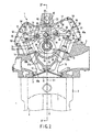
- Fig. 2 is a cross sectional view showing the positional relationship among a camshaft, an exhaust rocker arm, and an intake rocker arm in a four-cycle engine according to an embodiment of the invention.
- Fig. 3 is a cross sectional view taken along the line F3-F3 in Fig. 2.
- Fig. 4 is a plan view showing the positional relationship between the exhaust rocker arm and the intake rocker arm in a four-cycle engine according to an embodiment of the invention.
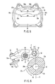
- Fig. 5 is a plan view showing tappet covers according to an embodiment of the invention.
- Fig. 6 is a cross sectional view showing a state, in which a roller bearing of the exhaust rocker arm is pushed up by a cam nose of an exhaust cam, in the embodiment of the invention.
- An embodiment of the invention will be described below with reference to the drawings.
- Fig. 1 shows a
motorcycle 100 according to an embodiment of the invention. Themotorcycle 100 comprises aframe 101. Theframe 101 comprises ahead pipe 102, left and right main frames 103 (only one of them being shown), and left and right rear-arm brackets 104 (only one of them being shown). - The
head pipe 102 is positioned at a front end of theframe 101 to support afront wheel 106 through afront fork 105. Themain frames 103 extend rearwardly of thehead pipe 102 and incline downward as they go rearwardly of thehead pipe 102. Themain frames 103 support afuel tank 107. - The rear-
arm brackets 104 project downward from rear ends of themain frames 103. The rear-arm brackets 104 pivotally support arear arm 108. Therear arm 108 extends rearwardly of the rear-arm brackets 104. Arear wheel 109 is supported at a rear end of therear arm 108. - Left and right seat rails 110 (only one of them being shown) are connected to upper ends of the rear-
arm brackets 104. The seat rails 110 pass above therear wheel 109 to extend rearwardly of the rear-arm brackets 104. The seat rails 110 support aseat 111. Theseat 111 is connected at its front end to thefuel tank 107. - As shown in Fig. 1, the
frame 101 supports a water-cooled four-cyclesingle cylinder engine 1, which drives therear wheel 109. Theengine 1 is disposed below themain frames 103 and supported by themain frames 103 and the rear-arm brackets 104. - As shown in Figs. 1 and 2, the
engine 1 comprises a crankcase 1a, acylinder block 2, and acylinder head 3. The crankcase 1a accommodates therein a crank shaft (not shown) . Thecylinder block 2 stands upright from an upper surface of the crankcase 1a. Thecylinder block 2 comprises acylinder 4. Thecylinder 4 accommodates therein apiston 5. Thepiston 5 is connected through a connectingrod 6 to the crank shaft. - The
cylinder head 3 is connected to an upper surface of thecylinder block 2. Thecylinder head 3 comprises arecess 7 on its surface opposed to thecylinder 4. Therecess 7 defines a pent rooftype combustion chamber 8 between it and a top surface of thepiston 5. - As shown in Figs. 2 and 4, the
cylinder head 3 comprises a pair ofexhaust ports intake ports exhaust ports intake ports combustion chamber 8 and arranged to be opposed to each other with a bore center line O1 of thecylinder 4, which passes through a center of thecombustion chamber 8, therebetween. - The
cylinder head 3 supports twoexhaust valves 12, which open and close theexhaust ports intake valves 13, which open and close theintake ports exhaust valves 12 are arranged in parallel to each other and inclined in a direction away from thebore center line 01 as they become more distant from thecombustion chamber 8. Valve stems 13a of theintake valves 13 are arranged in parallel to each other and inclined in an opposite direction to the valve stems 12a of theexhaust valves 12 relative to thebore center line 01. - The valve stems 12a of the
exhaust valves 12 are shorter in total length than the valve stems 13a of theintake valves 13. Therefore, tip ends of the valve stems 12a are positioned below tip ends of the valve stems 13a. - The
exhaust valves 12 are biased in a direction, in which theexhaust ports intake valves 13 are biased in a direction, in which theintake ports - As shown in Figs. 2 and 3, a
valve gear chamber 16 is formed within thecylinder head 3. Thevalve gear chamber 16 is positioned just above thecombustion chamber 8. Tip ends of the valve stems 12a of theexhaust valves 12 and tip ends of the valve stems 13a of theintake valves 13 project into thevalve gear chamber 16. - The
valve gear chamber 16 accommodates therein avalve gear 17 that drives theexhaust valves 12 and theintake valves 13. Thevalve gear 17 comprises asingle camshaft 18, anexhaust rocker arm 19 as a first rocker arm, and anintake rocker arm 20 as a second rocker arm. - The
camshaft 18 is supported at its one end and its other end throughbearings 21 by thecylinder head 3. A center X1 of rotation of thecamshaft 18 is perpendicular to thebore center line 01. One end of thecamshaft 18 is positioned in the vicinity of the bore center line O1 . Therefore, thecamshaft 18 is offset radially of thecylinder 4 relative to the bore center line O1. - The other end of the
camshaft 18 is disposed outside thevalve gear chamber 16. Asprocket 22 is fixed to the other end of thecamshaft 18. Acam chain 23 is stretched between thesprocket 22 and the crank shaft. According to the embodiment, thecamshaft 18 rotates forward in a counterclockwise direction (a direction of rotation of thefront wheel 106 when themotorcycle 100 advances) indicated by an arrow in Fig. 2. - As shown in Fig. 3, the
camshaft 18 comprises anexhaust cam 25 as a first valve gear cam, and anintake cam 26 as a second valve gear cam. Theexhaust cam 25 and theintake cam 26 are aligned axially of thecamshaft 18. When thecylinder head 3 is viewed axially of thecylinder 4, theexhaust cam 25 and theintake cam 26 are offset axially of thecamshaft 18 relative to thebore center line 01. An amount L1 of offset of theexhaust cam 25 relative to thebore center line 01 is larger than an amount L2 of offset of theintake cam 26 relative to thebore center line 01. - As shown in Fig. 2, the
exhaust cam 25 comprises abase circle 27a, which maintains theexhaust valves 12 in a closed state, and acam nose 27b, which actuates theexhaust valves 12 in a direction of opening. Thecam nose 27b extends beyond thebase circle 27a. - Likewise, the
intake cam 26 comprises a base circle 28a, which maintains theintake valves 13 in a closed state, and a camnose 28b, which actuates theintake valves 13 in a direction of opening. Thecam nose 28b extends beyond the base circle 28a. - As shown in Figs. 3 and 6,
oil jet ports exhaust cam 25 and theintake cam 26. Theoil jet port 29a is opened to an outer peripheral surface of thebase circle 27a of theexhaust cam 25. Theoil jet port 29b is opened to an outer peripheral surface of the base circle 28a of theintake cam 26. Theoil jet ports valve gear 17. Therefore, the lubricating oil pressurized by an oil pump jets on a circumference of thecamshaft 18 through theoil jet ports - As shown in Figs. 2 and 4, the
exhaust rocker arm 19 is swingably supported through afirst rocker shaft 30 on thecylinder head 3. Thefirst rocker shaft 30 is made in parallel to and disposed above thecamshaft 18. Further, thefirst rocker shaft 30 is positioned forwardly of thebore center line 01, which passes through the center X1 of rotation of thecamshaft 18, in a direction of rotation of thecamshaft 18. In other words, thefirst rocker shaft 30 is positioned between thecamshaft 18 and the valve stems 12a of theexhaust valves 12. - The
exhaust rocker arm 19 comprises a cylindrical-shapedboss 31, aroller support 32, and a pair ofpush arms boss 31 is swingably supported on thefirst rocker shaft 30. Theboss 31 is offset on one side in an axial direction of thefirst rocker shaft 30 relative to the bore center line O1. - The
roller support 32 is formed to bifurcate and to project toward theexhaust cam 25 from an outer peripheral surface of theboss 31. Theroller support 32 rotatably supports aroller bearing 34. Theroller bearing 34 is positioned at one end of theexhaust rocker arm 19 to come into rolling contact with thebase circle 27a and thecam nose 27b of theexhaust cam 25. A center X2 of rotation of theroller bearing 34 is offset toward thefirst rocker shaft 30 relative to the bore center line O1, which passes through the center X1 of rotation of thecamshaft 18. - As shown in Fig. 4, the
push arms exhaust valves 12 from the outer peripheral surface of theboss 31. The two valve stems 12a are evenly distributed with the bore center line O1 therebetween. In contrast, theboss 31 is offset on one side in the axial direction of thefirst rocker shaft 30 relative to thebore center line 01. Therefore, one 33a of the push arms and the other 33b of the push arms are different in length from each other. The other 33b of the push arms, which pushes thevalve stem 12a disposed away from theboss 31, crosses a line A, which extends radially of thecombustion chamber 8 to be perpendicular to the bore center line O1 and thecamshaft 18. - Projecting ends of the
push arms exhaust rocker arm 19 and opposed to the tip ends of the valve stems 12a. Adjust screws 35, respectively, are screwed into the projecting ends of thepush arms exhaust rocker arm 19 is across thefirst rocker shaft 30 from theexhaust cam 25 to extend toward the tip ends of the valve stems 12a of theexhaust valve 12. - Further, a pair of
oil supply ports 36 are formed on theboss 31 of theexhaust rocker arm 19. Theoil supply ports 36 receive the lubricating oil jetted from theoil jet ports camshaft 18 to conduct the same between theboss 31 and thefirst rocker shaft 30. Theoil supply ports 36 are away from each other in an axial direction of theboss 31. - As shown in Figs. 2 and 4, the
intake rocker arm 20 is swingably supported on thecylinder head 3 through asecond rocker shaft 38. Thesecond rocker shaft 38 is made in parallel to and dissposed above thecamshaft 18. Thesecond rocker shaft 38 is positioned rearwardly of the bore center line O1, which passes through the center X1 of rotation of thecamshaft 18, in the direction of rotation of thecamshaft 18. Therefore, thefirst rocker shaft 30 and thesecond rocker shaft 38 are arranged in parallel to each other with thecamshaft 18 therebetween. - The
intake rocker arm 20 comprises a cylindrical-shapedboss 39, aroller support 40, and a pair ofpush arms boss 39 is swingably supported on thesecond rocker shaft 38. Theboss 39 is offset on one side in an axial direction of thesecond rocker shaft 38 relative to the bore center line O1. - The
roller support 40 is formed to bifurcate and to project toward theintake cam 26 of thecamshaft 18 from an outer peripheral surface of theboss 39. Theroller support 40 supports aroller bearing 42. Theroller bearing 42 is positioned at one end of theintake rocker arm 20 to come into rolling contact with the base circle 28a and thecam nose 28b of theintake cam 26. A center X3 of rotation of theroller bearing 42 is offset toward thesecond rocker shaft 38 relative to thebore center line 01, which passes through the center X1 of rotation of thecamshaft 18. - As shown in Figs. 2 and 4, the
push arms intake valves 13 from an outer peripheral surface of theboss 39. The two valve stems 13a are evenly distributed with the bore center line O1 therebetween. - In contrast, the
boss 39 is offset on one side in the axial direction of thesecond rocker shaft 38 relative to the bore center line O1. Therefore, one 41a of the push arms and the other 41b of the push arms are different in length from each other. The other 41b of the push arms, which pushes thevalve stem 13a disposed away from theboss 39, crosses the line A. Further, a spacing D1 between projecting ends of thepush arms push arms exhaust rocker arm 19. - The projecting ends of the
push arms intake rocker arm 20 and opposed to the tip ends of the valve stems 13a. Adjust screws 43, respectively, are screwed into the projecting ends of thepush arms intake rocker arm 20 is across thesecond rocker shaft 38 from theintake cam 26 to extend toward the tip ends of the valve stems 13a of theintake valve 13. - A pair of
oil supply ports 44 are formed on theboss 39 of theintake rocker arm 20. Theoil supply ports 44 receive the lubricating oil jetted from theoil jet ports camshaft 18 to conduct the same between theboss 39 and thesecond rocker shaft 38. Theoil supply ports 44 are disposed away from each other in an axial direction of theboss 39. - As shown in Fig. 2, when the
roller bearing 34 on theexhaust rocker arm 19 contacts with thebase circle 27a of theexhaust cam 25, thefirst rocker shaft 30, which supports theexhaust rocker arm 19, is shifted closer to thecamshaft 18 along thebore center line 01 of thecylinder 4 than the center X2 of rotation of theroller bearing 34 is. In other words, a center X4 of thefirst rocker shaft 30 is disposed in a lower position than the center X2 of rotation of theroller bearing 34 as far as theroller bearing 34 contacts with thebase circle 27a. - Based on this, an intersecting angle θ1 is set to, for example, 92° where θ1 indicates an intersecting angle between a line B1, which connects between the center X4 of the
first rocker shaft 30 and the center X2 of rotation of theroller bearing 34, and a line B2, which connects between the center X1 of rotation of thecamshaft 18 and the center X2 of rotation of theroller bearing 34. - When the
roller bearing 42 on theintake rocker arm 20 contacts with the base circle 28a of theintake cam 26, thesecond rocker shaft 38, which supports theintake rocker arm 20, is shifted more distant from thecamshaft 18 than the center X3 of rotation of theroller bearing 42 is. In other words, a center X5 of thesecond rocker shaft 38 is disposed in a higher position than the center X3 of rotation of theroller bearing 42 as far as theroller bearing 42 contacts with the base circle 28a. - Therefore, an intersecting angle θ2 is set to, for example, 76° where θ2 indicates an intersecting angle between a line C1, which connects between the center X5 of the
second rocker shaft 38 and the center X3 of rotation of theroller bearing 42, and a line C2, which connects between the center X1 of rotation of thecamshaft 18 and the center X3 of rotation of theroller bearing 42. - Accordingly, the intersecting angle θ1 is larger than the intersecting angle θ2 (θ1 > θ2).
- As shown in Fig. 3, the
cylinder head 3 comprises arecess 46, which caves toward the center of thecombustion chamber 8. Therecess 46 is positioned in opposition to thecamshaft 18 with thebore center line 01 therebetween. Aplug mount hole 47 is formed at a bottom of therecess 46 to be opened to the center of thecombustion chamber 8. Anignitionplug 48 is screwed into theplug mount hole 47. An insulatingmaterial 48a of theignition plug 48 is positioned in therecess 46. - With
such cylinder head 3, thecamshaft 18 is offset radially of thecylinder 4 relative to the bore center line O1. Therefore, a large space for formation of therecess 46 can be ensured in that portion of thecylinder head 3, which is opposed to thecamshaft 18 with the bore center line O1 therebetween. As a result, therecess 46 can be made close to the bore center line O1, so that it is possible to have theignition plug 48 standing upright relative to thecombustion chamber 8. - As shown in Figs. 2 and 4, the
cylinder head 3 comprises afirst opening 50 and asecond opening 51, which are opened to thevalve gear chamber 16. Thefirst opening 50 serves for tappet adjustment of theexhaust valves 12, and are shaped in a manner to expose abutting portions of the valve stems 12a of theexhaust valves 12 and thepush arms exhaust rocker arm 19. Thefirst opening 50 is positioned at a front end of thecylinder head 3. - The
second opening 51 serves for tappet adjustment of theintake valves 13, and are shaped in a manner to expose abutting portions of the valve stems 13a of theintake valves 13 and thepush arms intake rocker arm 20. Thesecond opening 51 is positioned at a rear end of thecylinder head 3. The first andsecond openings - As shown in Fig. 2, the first and
second openings tappet cover 52, which covers thefirst opening 50, and thetappet cover 52, which covers thesecond opening 51, are common to each other and fixed to thecylinder head 3 in a removable manner. - The tappet covers 52 comprise an inner surface exposed to the
valve gear chamber 16. First andsecond walls second walls valve gear chamber 16 so as to receive the lubricating oil jetted from theoil jet ports camshaft 18. The first andsecond walls cylinder head 3, and extend axially of the first andsecond rocker shafts - As shown in Fig. 5, the
first wall 54 is positioned above thesecond wall 55. Thefirst wall 54 comprises a pair of V-shaped oil guides 56a, 56b. The oil guides 56a, 56b comprisesupply ports tappet cover 52 and have the lubricating oil, which is received by thefirst wall 54, dripping. A spacing D3 between thesupply ports push arms exhaust rocker arm 19. - The
second wall 55 positioned below thefirst wall 54 comprises a pair of V-shaped oil guides 58a, 58b. The oil guides 58a, 58b comprisesupply ports tappet cover 52 and have the lubricating oil, which is received by thesecond wall 55, dripping. A spacing D4 between thesupply ports push arms intake rocker arm 20. - By virtue of this, the
supply ports first wall 54 are positioned just above the projecting ends of thepush arms exhaust rocker arm 19 in a state, in which thefirst opening 50 on an exhaust side is covered by thetappet cover 52. Accordingly, the lubricating oil is supplied through thesupply ports screws 35 and the valve stems 12a of theexhaust valves 12. - Likewise, the
supply ports second wall 55 are positioned just above the projecting ends of thepush arms intake rocker arm 20 in a state, in which thesecond opening 51 on an intake side is covered by thetappet cover 52. Accordingly, the lubricating oil is supplied through thesupply ports screws 43 and the valve stems 13a of theintake valves 13. - Accordingly, although the
first opening 50 on the exhaust side and thesecond opening 51 on the intake side are covered by the common tappet covers 52, it is possible to surely supply the lubricating oil to the abutting portions of the adjustscrews 35 and theexhaust valves 12 and the abutting portions of the adjustscrews 43 and theintake valves 13. - In particular, according to the embodiment, the
boss 31 of theexhaust rocker arm 19 and theboss 39 of theintake rocker arm 20 are offset relative to thebore center line 01 axially of the first andsecond rocker shafts oil jet ports camshaft 18, from which the lubricating oil is jetted, are distant from thevalve stem 12a of the other of theexhaust valves 12 and thevalve stem 13a of the other of theintake valves 13. As a result, the lubricating conditions of the other of theexhaust valves 12 and the other of theintake valves 13 become strict at the time of idling operation, at which the lubricating oil is jetted in small amount. - With the above constitution, the lubricating oil can be supplied to the abutting portions of the adjust
screws 35 and the other of theexhaust valves 12 and the abutting portions of the adjustscrews 43 and the other of theintake valves 13 from thesupply ports oil jet ports - Subsequently, an operation of the
valve gear 17 will be described with reference to Fig. 6. - Fig. 2 shows a state, in which the
roller bearing 34 on theexhaust rocker arm 19 and theroller bearing 42 on theintake rocker arm 20, respectively, contact with thebase circle 27a of theexhaust cam 25 and the base circle 28a of theintake cam 26. At this time, theexhaust valves 12 and theintake valves 13 are closed. - When the
camshaft 18 rotates forward in a counterclockwise direction indicated by the arrow in Fig. 2, theroller bearing 34 on theexhaust rocker arm 19 gets on thecam nose 27b from thebase circle 27a of theexhaust cam 25. Thecam nose 27b pushes up theroller bearing 34 of theexhaust rocker arm 19. Therefore, theexhaust rocker arm 19 swings on thefirst rocker shaft 30, and thepush arms exhaust rocker arm 19 push down the valve stems 12a of theexhaust valves 12. Accordingly, theexhaust valves 12 are opened. - Succeedingly, the
roller bearing 42 on theintake rocker arm 20 gets on thecam nose 28b from the base circle 28a of theintake cam 26. Thecam nose 28b pushes up theroller bearing 42 of theintake rocker arm 20. Therefore, theintake rocker arm 20 swings on thesecond rocker shaft 38, and thepush arms intake rocker arm 20 push down the valve stems 13a of theintake valves 13. Accordingly, theintake valves 13 are opened. - The
second rocker shaft 38, which supports theintake rocker arm 20, is positioned rearwardly of thebore center line 01, which passes through the center X1 of rotation of thecamshaft 18, in the direction of rotation of thecamshaft 18. Therefore, thecam nose 28b of theintake cam 26 is moved in a direction away from thesecond rocker shaft 38 in a process, in which thecam nose 28b pushes up theroller bearing 42. - Accordingly, the
second rocker shaft 38 will not be positioned in a direction, in which theroller bearing 42 is pushed up. As a result, a force, with which thecam nose 28b pushes up theroller bearing 42, acts as a force, by which theintake rocker arm 20 is caused to swing on thesecond rocker shaft 38. - On the other hand, the
first rocker shaft 30, which supports theexhaust rocker arm 19, is positioned forwardly of the bore center line O1 which passes through the center X1 of rotation of thecamshaft 18, in the direction of rotation of thecamshaft 18. Thefirst rocker shaft 30 is disposed in a lower position than the center X2 of rotation of theroller bearing 34 when theroller bearing 34 of theexhaust rocker arm 19 contacts with thebase circle 27a of theexhaust cam 25. - By virtue of this, the
first rocker shaft 30 will not be positioned in a direction, in which theroller bearing 34 is pushed up, in a process, in which thecam nose 27b of theexhaust cam 25 pushes up theroller bearing 34. Accordingly, a force F exerted on a contact portion, at which thecam nose 27b and theroller bearing 34 contact with each other, acts in a different direction from that of the line B1, which connects between the center X2 of rotation of theroller bearing 34 and the center X4 of thefirst rocker shaft 30, as shown by an arrow in fig. 6. - In other words, the
valve gear 17 prescribes the relationship of relative positions of the center X4 of thefirst rocker shaft 30, the center X2 of rotation of theroller bearing 34 of theexhaust rocker arm 19, and the center X1 of rotation of thecamshaft 18 such that theexhaust rocker arm 19 does not buckle when theexhaust rocker arm 19 swings in a direction, in which theexhaust valves 12 is opened. - As a result, although the
first rocker shaft 30 is positioned forwardly of the bore center line O1 in the direction of rotation of thecamshaft 18, theexhaust rocker arm 19 becomes hard to bear a buckling load. Therefore, it is possible to decrease a load being born by theexhaust rocker arm 19, so that it is not necessary to take measures of large-scaled reinforcement to enable theexhaust rocker arm 19 to withstand a buckling load. Accordingly, theexhaust rocker arm 19 can be formed to be lightweight and compact. - Further, with the above constitution, most of a force, with which the
cam nose 27b pushes up theroller bearing 34, can be made effective use of as a force that swings theexhaust rocker arm 19. Thereby, theexhaust rocker arm 19 swings smoothly. Accordingly, it is possible to make theexhaust rocker arm 19 lightweight and to reasonably cope with high-speed rotation of theengine 1. - In addition, since the
first rocker shaft 30 is positioned to be lower than thecamshaft 18, the upper surface of thecylinder head 3 can be lowered in position. Accordingly, there is produced an advantage of contributions to compactness of thecylinder head 3. - The invention is not limited to the above embodiments but can be carried out in various modifications within the scope not departing from the gist of the invention.
- While the above embodiments are directed to a so-called four-valve engine, in which a pair of exhaust valves and a pair of intake valves are provided in one combustion chamber, the invention is not limited thereto. The invention can be carried out in, for example, a two-valve engine, in which one exhaust valve and one intake valve are provided in one combustion chamber, or likewise in a three-valve engine, in which one exhaust valve and a pair of intake valves are provided in one combustion chamber.
- In addition, the rocker arm supported by the first rocker shaft, which is positioned forward in the direction of rotation of the camshaft, is not limited to one that drives the exhaust valves but may be one that drives the intake valves.
- Further, there is no need of arranging the camshaft on the bore center line. For example, the camshaft may be offset toward the exhaust valves or the intake valves relative to the bore center line.
- According to the invention, the first rocker arm becomes hard to bear a buckling load, so that it is possible to decrease a load being born by the first rocker arm. Accordingly, it is not necessary to take measures of large-scaled reinforcement to enable the first rocker arm to withstand a buckling load, so that the first rocker arm can be made small-sized and lightweight.
Claims (10)
- A valve gear comprising
a camshaft having a first valve gear cam and a second valve gear cam,
first and second rocker shafts arranged in a manner to interpose therebetween the camshaft,
a first rocker arm swingably supported on the first rocker shaft and having at one end thereof a roller bearing, which comes into rolling contact with the first valve gear cam, and
a second rocker arm swingably supported on the second rocker shaft and having at one end thereof a roller bearing, which comes into rolling contact with the second valve gear cam, and
wherein the first and second valve gear cams of the camshaft, respectively, comprise a base circle, and a cam nose projecting from the base circle, the first rocker shaft, which supports the first rocker arm, is positioned forwardly of a center line, which passes through a center of the camshaft to extend axially of a cylinder, in a direction of rotation of the camshaft, and the second rocker shaft, which supports the second rocker arm, is positioned rearwardly of the center line in the direction of rotation of the camshaft, and
wherein when the roller bearing of the first rocker arm contacts with the base circle of the first valve gear cam, the first rocker shaft is shifted closer to the camshaft than a center of rotation of the roller bearing is. - The valve gear according to claim 1, wherein the roller bearing of the first rocker arm and the roller bearing of the second rocker arm, respectively, are offset relative to the center line of the cylinder in an axial direction of the camshaft, and the roller bearing of the first rocker arm is larger in offset relative to the center line than the roller bearing of the second rocker arm.
- The valve gear according to claim 1 or 2, wherein the first rocker arm opens and closes at least one exhaust valve and the second rocker arm opens and closes at least one intake valve.
- A valve gear comprising
a camshaft having a first valve gear cam and a second valve gear cam,
first and second rocker shafts arranged in a manner to interpose therebetween the camshaft,
a first rocker arm swingably supported on the first rocker shaft and having at one end thereof a roller bearing, which comes into rolling contact with the first valve gear cam, and
a second rocker arm swingably supported on the second rocker shaft and having at one end thereof a roller bearing, which comes into rolling contact with the second valve gear cam, and
wherein the first and second valve gear cams of the camshaft, respectively, comprise a base circle, and a cam nose projecting from the base circle, the first rocker shaft, which supports the first rocker arm, is positioned forwardly of a center line, which passes through a center of rotation of the camshaft to extend axially of a cylinder, in a direction of rotation of the camshaft, and the second rocker arm, which supports the second rocker arm, is positioned rearwardly of the center line in the direction of rotation of the camshaft, and
wherein the relationship of relative positions of a center of the first rocker shaft, a center of rotation of the roller bearing of the first rocker arm, and a center of rotation of the camshaft is prescribed so that the first rocker arm does not buckle when the cam nose of the first valve gear cam contacts with the roller bearing of the first rocker arm to cause the first rocker arm to swing in a valve opening direction. - The valve gear according to claim 4, wherein the following relationship is satisfied θ1 > θ2
where θ1 indicates an intersecting angle between a line, which connects between the center of the first rocker shaft and the center of rotation of the roller bearing of the first rocker arm, and a line, which connects between the center of rotation of the camshaft and the center of rotation of the roller bearing of the first rocker arm, and θ2 indicates an intersecting angle between a line, which connects between a center of the second rocker shaft and a center of rotation of the roller bearing of the second rocker arm, and a line, which connects between the center of rotation of the camshaft and the center of rotation of the roller bearing of the second rocker arm. - The valve gear according to claim 5, wherein the intersecting angle θ1 is larger than 90 degrees and the intersecting angle θ2 is smaller than 90 degrees.
- The valve gear according to any one of claims 4 to 6, wherein the first rocker arm opens and closes at least one exhaust valve and the second rocker arm opens and closes at least one intake valve.
- A four-cycle engine comprising
a cylinder having a bore center line,
a cylinder head connected to the cylinder and having an exhaust valve and an intake valve,
a camshaft supported by the cylinder head and having a first valve gear cam and a second valve gear cam,
first and second rocker shafts arranged in a manner to interpose therebetween the camshaft,
a first rocker arm swingably supported on the first rocker shaft and having at one end thereof a roller bearing, which comes into rolling contact with the first valve gear cam, the first rocker arm acting to drive one of the exhaust valve and the intake valve, and
a second rocker arm swingably supported on the second rocker shaft and having at one end thereof a roller bearing, which comes into rolling contact with the second valve gear cam, the second rocker arm acting to drive the other of the exhaust valve and the intake valve, and
wherein the first and second valve gear cams of the camshaft, respectively, comprise a base circle, and a cam nose projecting from the base circle, the first rocker shaft, which supports the first rocker arm, is positioned forwardly of the bore center line, which passes through a center of the camshaft, in a direction of rotation of the camshaft, and the second rocker shaft, which supports the second rocker arm, is positioned rearwardly of the bore center line in the direction of rotation of the camshaft, and
wherein when the roller bearing of the first rocker arm contacts with the base circle of the first valve gear cam, the first rocker shaft is shifted closer to the camshaft than a center of rotation of the roller bearing is. - The four-cycle engine according to claim 8, wherein the exhaust valve and the intake valve, respectively, comprise a valve stem, and the first rocker arm and the second rocker arm, respectively, comprise the other end to push the valve stem, and
wherein the cylinder head comprises a first opening to expose abutting portions of the other end of the first rocker arm and the valve stem, and a second opening to expose abutting portions of the other end of the second rocker arm and the valve stem, the first opening and the second opening being arranged to be opposed to each other with the bore center line therebetween and covered by respective common removable covers, and
the covers comprise first and second walls on inner surfaces thereof, which are opposed to the abutting portions, to receive a lubricating oil, the first wall being formed with supply ports, through which the lubricating oil is conducted to the abutting portions of the other end of the first rocker arm and the valve stem, and the second wall being formed with supply ports, through which the lubricating oil is conducted to the abutting portions of the other end of the second rocker arm and the valve stem. - A motorcycle comprising a frame, and
a four-cycle engine supported on the frame,
the four-cycle engine comprising
a cylinder having a bore center line,
a cylinder head connected to the cylinder and having an exhaust valve and an intake valve,
a camshaft supported by the cylinder head and having a first valve gear cam and a second valve gear cam,
first and second rocker shafts arranged in a manner to interpose therebetween the camshaft,
a first rocker arm swingably supported on the first rocker shaft and having at one end thereof a roller bearing, which comes into rolling contact with the first valve gear cam, the first rocker arm acting to drive one of the exhaust valve and the intake valve, and
a second rocker arm swingably supported on the second rocker shaft and having at one end thereof a roller bearing, which comes into rolling contact with the second valve gear cam, the second rocker arm acting to drive the other of the exhaust valve and the intake valve, and
wherein the first and secondvalve gear cams of the camshaft, respectively, comprise a base circle, and a cam nose projecting from the base circle, the first rocker shaft, which supports the first rocker arm, is positioned forwardly of the bore center line, which passes through a center of the camshaft, in a direction of rotation of the camshaft, and the second rocker shaft, which supports the second rocker arm, is positioned rearwardly of the bore center line in the direction of rotation of the camshaft, and
wherein when the roller bearing of the first rocker arm contacts with the base circle of the first valve gear cam, the first rocker shaft is shifted closer to the camshaft than a center of rotation of the roller bearing is.
Applications Claiming Priority (2)
| Application Number | Priority Date | Filing Date | Title |
|---|---|---|---|
| JP2003207668 | 2003-08-18 | ||
| PCT/JP2004/010879 WO2005017322A1 (en) | 2003-08-18 | 2004-07-23 | Valve operating mechanism with roller rocker arm, 4-cycle engine, and motorcycle having 4-cycle engine mounted thereon |
Publications (3)
| Publication Number | Publication Date |
|---|---|
| EP1683944A1 true EP1683944A1 (en) | 2006-07-26 |
| EP1683944A4 EP1683944A4 (en) | 2009-07-15 |
| EP1683944B1 EP1683944B1 (en) | 2013-06-05 |
Family
ID=34190065
Family Applications (1)
| Application Number | Title | Priority Date | Filing Date |
|---|---|---|---|
| EP04748087.6A Expired - Lifetime EP1683944B1 (en) | 2003-08-18 | 2004-07-23 | Valve operating mechanism with roller rocker arm, 4-cycle engine, and motorcycle having 4-cycle engine mounted thereon |
Country Status (5)
| Country | Link |
|---|---|
| US (1) | US7204219B2 (en) |
| EP (1) | EP1683944B1 (en) |
| JP (1) | JP4054041B2 (en) |
| CN (1) | CN100434658C (en) |
| WO (1) | WO2005017322A1 (en) |
Cited By (1)
| Publication number | Priority date | Publication date | Assignee | Title |
|---|---|---|---|---|
| DE102007012734A1 (en) * | 2007-03-16 | 2008-09-18 | Schaeffler Kg | Rocker arm for valve gear of internal combustion engine in e.g. two-wheeler, has axle bearing integrated in crossbar, formed as half-shell and aligned with opening, where half shell has uniform radius, which is adapted to radius of openings |
Families Citing this family (24)
| Publication number | Priority date | Publication date | Assignee | Title |
|---|---|---|---|---|
| US7395790B2 (en) | 2004-11-18 | 2008-07-08 | S&S Cycle, Inc. | Reed valve breather for evolution engine |
| JP2006283623A (en) * | 2005-03-31 | 2006-10-19 | Honda Motor Co Ltd | Lubrication structure of internal combustion engine |
| US8258161B2 (en) * | 2007-03-02 | 2012-09-04 | Merck Sharp & Dohme Corp. | Crystalline salt form of an antidiabetic compound |
| US9187083B2 (en) | 2009-09-16 | 2015-11-17 | Polaris Industries Inc. | System and method for charging an on-board battery of an electric vehicle |
| EP2308708B1 (en) * | 2009-09-16 | 2016-08-17 | swissauto powersport llc | Electric vehicle with range extension |
| JP6118057B2 (en) * | 2012-09-28 | 2017-04-19 | 本田技研工業株式会社 | Rocker shaft arrangement structure of 4-stroke internal combustion engine |
| CN103277166B (en) | 2013-06-17 | 2016-06-08 | 苏州科瓴精密机械科技有限公司 | Otto cycle engine |
| CN103487257B (en) * | 2013-10-15 | 2015-12-16 | 山东森德数控机械有限公司 | Pressure pulse test bench of intercooler servo reversing arrangement |
| US10300786B2 (en) | 2014-12-19 | 2019-05-28 | Polaris Industries Inc. | Utility vehicle |
| CN118849684A (en) | 2015-05-15 | 2024-10-29 | 北极星工业有限公司 | Multi-purpose vehicles |
| EP3468823B1 (en) | 2016-06-14 | 2024-09-04 | Polaris Industries Inc. | Hybrid utility vehicle |
| JP6737072B2 (en) * | 2016-08-29 | 2020-08-05 | スズキ株式会社 | Overhead valve actuation mechanism of engine |
| CN107939467B (en) * | 2017-12-28 | 2023-12-15 | 潍柴动力股份有限公司 | Valve intake and exhaust rocker arm structure and diesel engine |
| US10780770B2 (en) | 2018-10-05 | 2020-09-22 | Polaris Industries Inc. | Hybrid utility vehicle |
| CA3299418A1 (en) | 2019-04-30 | 2026-03-02 | Polaris Industries Inc. | Vehicle with removable final drive |
| US11370266B2 (en) | 2019-05-16 | 2022-06-28 | Polaris Industries Inc. | Hybrid utility vehicle |
| CN111322129A (en) * | 2020-03-09 | 2020-06-23 | 江门市大长江集团有限公司 | Engine and support mechanism for valve guide |
| US12187127B2 (en) | 2020-05-15 | 2025-01-07 | Polaris Industries Inc. | Off-road vehicle |
| US11691674B2 (en) | 2020-05-15 | 2023-07-04 | Polaris Industries Inc. | Off-road vehicle |
| CN111651834B (en) * | 2020-05-21 | 2023-08-01 | 安徽航瑞航空动力装备有限公司 | Method for arranging double-valve mechanism of engine |
| US12485981B2 (en) | 2021-03-24 | 2025-12-02 | Polaris Industries Inc. | Electric recreational vehicle |
| CA3156559A1 (en) | 2021-05-05 | 2022-11-05 | Polaris Industries Inc. | Exhaust assembly for a utility vehicle |
| CN113464231B (en) * | 2021-07-15 | 2022-03-11 | 哈尔滨工程大学 | A horizontal intake and exhaust gas distribution device |
| MX2023006716A (en) | 2022-06-13 | 2023-12-14 | Polaris Inc | POWER TRAIN FOR UTILITY VEHICLE. |
Family Cites Families (11)
| Publication number | Priority date | Publication date | Assignee | Title |
|---|---|---|---|---|
| JPS54145736U (en) * | 1978-03-31 | 1979-10-09 | ||
| JPH0768892B2 (en) | 1985-10-09 | 1995-07-26 | 本田技研工業株式会社 | OHC type valve operating device for internal combustion engine |
| JPH07116924B2 (en) * | 1987-05-22 | 1995-12-18 | 本田技研工業株式会社 | Valve drive for internal combustion engine |
| JPH0759884B2 (en) * | 1988-12-13 | 1995-06-28 | 株式会社クボタ | Lubrication system for valve mechanism of overhead valve engine |
| JP2566480B2 (en) * | 1990-06-15 | 1996-12-25 | 本田技研工業株式会社 | Fuel injection internal combustion engine |
| US5123384A (en) * | 1991-10-21 | 1992-06-23 | Henley Manufacturing Holding Company, Inc. | Pedestal-mounted rocker arm with bushing |
| JPH0768892A (en) | 1993-09-07 | 1995-03-14 | Casio Electron Mfg Co Ltd | Printer |
| JP3313843B2 (en) * | 1993-09-28 | 2002-08-12 | 本田技研工業株式会社 | Internal combustion engine |
| US6705264B2 (en) * | 1998-12-24 | 2004-03-16 | Yamaha Marine Kabushiki Kaisha | Valve control for outboard motor engine |
| DE20022223U1 (en) | 2000-05-12 | 2001-05-10 | DaimlerChrysler AG, 70567 Stuttgart | Gas exchange valve in an internal combustion engine |
| JP2001336407A (en) * | 2000-05-29 | 2001-12-07 | Sanshin Ind Co Ltd | Valve driving mechanism of engine for outboard motor |
-
2004
- 2004-07-23 US US10/527,248 patent/US7204219B2/en not_active Expired - Lifetime
- 2004-07-23 WO PCT/JP2004/010879 patent/WO2005017322A1/en not_active Ceased
- 2004-07-23 CN CNB2004800227927A patent/CN100434658C/en not_active Expired - Lifetime
- 2004-07-23 JP JP2005513149A patent/JP4054041B2/en not_active Expired - Lifetime
- 2004-07-23 EP EP04748087.6A patent/EP1683944B1/en not_active Expired - Lifetime
Cited By (1)
| Publication number | Priority date | Publication date | Assignee | Title |
|---|---|---|---|---|
| DE102007012734A1 (en) * | 2007-03-16 | 2008-09-18 | Schaeffler Kg | Rocker arm for valve gear of internal combustion engine in e.g. two-wheeler, has axle bearing integrated in crossbar, formed as half-shell and aligned with opening, where half shell has uniform radius, which is adapted to radius of openings |
Also Published As
| Publication number | Publication date |
|---|---|
| EP1683944B1 (en) | 2013-06-05 |
| EP1683944A4 (en) | 2009-07-15 |
| WO2005017322A1 (en) | 2005-02-24 |
| US20060096564A1 (en) | 2006-05-11 |
| CN100434658C (en) | 2008-11-19 |
| JP4054041B2 (en) | 2008-02-27 |
| US7204219B2 (en) | 2007-04-17 |
| CN1833096A (en) | 2006-09-13 |
| JPWO2005017322A1 (en) | 2006-10-12 |
Similar Documents
| Publication | Publication Date | Title |
|---|---|---|
| EP1683944B1 (en) | Valve operating mechanism with roller rocker arm, 4-cycle engine, and motorcycle having 4-cycle engine mounted thereon | |
| CA2650895C (en) | Cylinder head structure in four-cycle engine | |
| US8251031B2 (en) | Rocker shaft support structure in four-cycle engine | |
| AU2003242499B2 (en) | Four-cycle Engine | |
| JP3982917B2 (en) | Variable valve operating device for internal combustion engine | |
| EP0967367B1 (en) | Valve drive system for an internal combustion engine | |
| CN100396888C (en) | Valve trains for internal combustion engines | |
| EP1707770A1 (en) | Valve system of engine | |
| JP2010048206A (en) | Valve gear for engine | |
| JP2010053748A (en) | Cam housing structure of engine for motorcycle | |
| EP1403497B1 (en) | Camshaft bearing structure for over-head camshaft type internal combustion engine | |
| US6453861B1 (en) | Valve gear of internal combustion engine | |
| US7584733B2 (en) | Mounting structure of ignition plug tube | |
| JP4148608B2 (en) | Roller type rocker arm | |
| EP1452699B1 (en) | Whirl-stop device for rocker arm shaft in valve mechanism of internal combustion engine | |
| JP4117481B2 (en) | Variable valve operating device for internal combustion engine | |
| JP5499557B2 (en) | Valve gear | |
| US10316701B2 (en) | Overhead valve actuation mechanism for engine | |
| CN107575273B (en) | Variable valve mechanism, engine, and motorcycle | |
| JP4546674B2 (en) | Rocker arm roller lubrication structure | |
| JP2001193426A (en) | Valve train for internal combustion engine | |
| AU7246400A (en) | Valve operating system in internal combustion engine | |
| JPS63235606A (en) | One-overhead camshaft type engine | |
| JP2001182513A (en) | Valve train for internal combustion engine | |
| JP2005146955A (en) | Variable valve operating device for internal combustion engine |
Legal Events
| Date | Code | Title | Description |
|---|---|---|---|
| PUAI | Public reference made under article 153(3) epc to a published international application that has entered the european phase |
Free format text: ORIGINAL CODE: 0009012 |
|
| 17P | Request for examination filed |
Effective date: 20060220 |
|
| AK | Designated contracting states |
Kind code of ref document: A1 Designated state(s): AT BE BG CH CY CZ DE DK EE ES FI FR GB GR HU IE IT LI LU MC NL PL PT RO SE SI SK TR |
|
| DAX | Request for extension of the european patent (deleted) | ||
| A4 | Supplementary search report drawn up and despatched |
Effective date: 20090617 |
|
| RIC1 | Information provided on ipc code assigned before grant |
Ipc: F01L 1/18 20060101AFI20050302BHEP Ipc: F01M 9/08 20060101ALI20090610BHEP |
|
| 17Q | First examination report despatched |
Effective date: 20101201 |
|
| GRAP | Despatch of communication of intention to grant a patent |
Free format text: ORIGINAL CODE: EPIDOSNIGR1 |
|
| GRAS | Grant fee paid |
Free format text: ORIGINAL CODE: EPIDOSNIGR3 |
|
| GRAA | (expected) grant |
Free format text: ORIGINAL CODE: 0009210 |
|
| RIN1 | Information on inventor provided before grant (corrected) |
Inventor name: SAKURAI, MOTOKI, |
|
| AK | Designated contracting states |
Kind code of ref document: B1 Designated state(s): AT BE BG CH CY CZ DE DK EE ES FI FR GB GR HU IE IT LI LU MC NL PL PT RO SE SI SK TR |
|
| REG | Reference to a national code |
Ref country code: GB Ref legal event code: FG4D |
|
| REG | Reference to a national code |
Ref country code: CH Ref legal event code: EP |
|
| REG | Reference to a national code |
Ref country code: AT Ref legal event code: REF Ref document number: 615789 Country of ref document: AT Kind code of ref document: T Effective date: 20130615 |
|
| REG | Reference to a national code |
Ref country code: IE Ref legal event code: FG4D |
|
| REG | Reference to a national code |
Ref country code: DE Ref legal event code: R096 Ref document number: 602004042360 Country of ref document: DE Effective date: 20130801 |
|
| REG | Reference to a national code |
Ref country code: AT Ref legal event code: MK05 Ref document number: 615789 Country of ref document: AT Kind code of ref document: T Effective date: 20130605 |
|
| PG25 | Lapsed in a contracting state [announced via postgrant information from national office to epo] |
Ref country code: GR Free format text: LAPSE BECAUSE OF FAILURE TO SUBMIT A TRANSLATION OF THE DESCRIPTION OR TO PAY THE FEE WITHIN THE PRESCRIBED TIME-LIMIT Effective date: 20130906 Ref country code: FI Free format text: LAPSE BECAUSE OF FAILURE TO SUBMIT A TRANSLATION OF THE DESCRIPTION OR TO PAY THE FEE WITHIN THE PRESCRIBED TIME-LIMIT Effective date: 20130605 Ref country code: ES Free format text: LAPSE BECAUSE OF FAILURE TO SUBMIT A TRANSLATION OF THE DESCRIPTION OR TO PAY THE FEE WITHIN THE PRESCRIBED TIME-LIMIT Effective date: 20130916 Ref country code: AT Free format text: LAPSE BECAUSE OF FAILURE TO SUBMIT A TRANSLATION OF THE DESCRIPTION OR TO PAY THE FEE WITHIN THE PRESCRIBED TIME-LIMIT Effective date: 20130605 Ref country code: SE Free format text: LAPSE BECAUSE OF FAILURE TO SUBMIT A TRANSLATION OF THE DESCRIPTION OR TO PAY THE FEE WITHIN THE PRESCRIBED TIME-LIMIT Effective date: 20130605 Ref country code: SI Free format text: LAPSE BECAUSE OF FAILURE TO SUBMIT A TRANSLATION OF THE DESCRIPTION OR TO PAY THE FEE WITHIN THE PRESCRIBED TIME-LIMIT Effective date: 20130605 |
|
| REG | Reference to a national code |
Ref country code: NL Ref legal event code: VDEP Effective date: 20130605 |
|
| PG25 | Lapsed in a contracting state [announced via postgrant information from national office to epo] |
Ref country code: PL Free format text: LAPSE BECAUSE OF FAILURE TO SUBMIT A TRANSLATION OF THE DESCRIPTION OR TO PAY THE FEE WITHIN THE PRESCRIBED TIME-LIMIT Effective date: 20130605 Ref country code: BG Free format text: LAPSE BECAUSE OF FAILURE TO SUBMIT A TRANSLATION OF THE DESCRIPTION OR TO PAY THE FEE WITHIN THE PRESCRIBED TIME-LIMIT Effective date: 20130905 |
|
| PG25 | Lapsed in a contracting state [announced via postgrant information from national office to epo] |
Ref country code: PT Free format text: LAPSE BECAUSE OF FAILURE TO SUBMIT A TRANSLATION OF THE DESCRIPTION OR TO PAY THE FEE WITHIN THE PRESCRIBED TIME-LIMIT Effective date: 20131007 Ref country code: EE Free format text: LAPSE BECAUSE OF FAILURE TO SUBMIT A TRANSLATION OF THE DESCRIPTION OR TO PAY THE FEE WITHIN THE PRESCRIBED TIME-LIMIT Effective date: 20130605 Ref country code: BE Free format text: LAPSE BECAUSE OF FAILURE TO SUBMIT A TRANSLATION OF THE DESCRIPTION OR TO PAY THE FEE WITHIN THE PRESCRIBED TIME-LIMIT Effective date: 20130605 Ref country code: SK Free format text: LAPSE BECAUSE OF FAILURE TO SUBMIT A TRANSLATION OF THE DESCRIPTION OR TO PAY THE FEE WITHIN THE PRESCRIBED TIME-LIMIT Effective date: 20130605 Ref country code: CZ Free format text: LAPSE BECAUSE OF FAILURE TO SUBMIT A TRANSLATION OF THE DESCRIPTION OR TO PAY THE FEE WITHIN THE PRESCRIBED TIME-LIMIT Effective date: 20130605 |
|
| PG25 | Lapsed in a contracting state [announced via postgrant information from national office to epo] |
Ref country code: NL Free format text: LAPSE BECAUSE OF FAILURE TO SUBMIT A TRANSLATION OF THE DESCRIPTION OR TO PAY THE FEE WITHIN THE PRESCRIBED TIME-LIMIT Effective date: 20130605 Ref country code: RO Free format text: LAPSE BECAUSE OF FAILURE TO SUBMIT A TRANSLATION OF THE DESCRIPTION OR TO PAY THE FEE WITHIN THE PRESCRIBED TIME-LIMIT Effective date: 20130605 |
|
| REG | Reference to a national code |
Ref country code: CH Ref legal event code: PL |
|
| PG25 | Lapsed in a contracting state [announced via postgrant information from national office to epo] |
Ref country code: MC Free format text: LAPSE BECAUSE OF FAILURE TO SUBMIT A TRANSLATION OF THE DESCRIPTION OR TO PAY THE FEE WITHIN THE PRESCRIBED TIME-LIMIT Effective date: 20130605 |
|
| PLBE | No opposition filed within time limit |
Free format text: ORIGINAL CODE: 0009261 |
|
| STAA | Information on the status of an ep patent application or granted ep patent |
Free format text: STATUS: NO OPPOSITION FILED WITHIN TIME LIMIT |
|
| REG | Reference to a national code |
Ref country code: IE Ref legal event code: MM4A |
|
| PG25 | Lapsed in a contracting state [announced via postgrant information from national office to epo] |
Ref country code: DK Free format text: LAPSE BECAUSE OF FAILURE TO SUBMIT A TRANSLATION OF THE DESCRIPTION OR TO PAY THE FEE WITHIN THE PRESCRIBED TIME-LIMIT Effective date: 20130605 Ref country code: LI Free format text: LAPSE BECAUSE OF NON-PAYMENT OF DUE FEES Effective date: 20130731 Ref country code: CH Free format text: LAPSE BECAUSE OF NON-PAYMENT OF DUE FEES Effective date: 20130731 |
|
| 26N | No opposition filed |
Effective date: 20140306 |
|
| REG | Reference to a national code |
Ref country code: DE Ref legal event code: R097 Ref document number: 602004042360 Country of ref document: DE Effective date: 20140306 |
|
| PG25 | Lapsed in a contracting state [announced via postgrant information from national office to epo] |
Ref country code: IE Free format text: LAPSE BECAUSE OF NON-PAYMENT OF DUE FEES Effective date: 20130723 |
|
| PG25 | Lapsed in a contracting state [announced via postgrant information from national office to epo] |
Ref country code: TR Free format text: LAPSE BECAUSE OF FAILURE TO SUBMIT A TRANSLATION OF THE DESCRIPTION OR TO PAY THE FEE WITHIN THE PRESCRIBED TIME-LIMIT Effective date: 20130605 Ref country code: CY Free format text: LAPSE BECAUSE OF FAILURE TO SUBMIT A TRANSLATION OF THE DESCRIPTION OR TO PAY THE FEE WITHIN THE PRESCRIBED TIME-LIMIT Effective date: 20130605 |
|
| PG25 | Lapsed in a contracting state [announced via postgrant information from national office to epo] |
Ref country code: HU Free format text: LAPSE BECAUSE OF FAILURE TO SUBMIT A TRANSLATION OF THE DESCRIPTION OR TO PAY THE FEE WITHIN THE PRESCRIBED TIME-LIMIT; INVALID AB INITIO Effective date: 20040723 Ref country code: LU Free format text: LAPSE BECAUSE OF NON-PAYMENT OF DUE FEES Effective date: 20130723 |
|
| REG | Reference to a national code |
Ref country code: FR Ref legal event code: PLFP Year of fee payment: 13 |
|
| REG | Reference to a national code |
Ref country code: FR Ref legal event code: PLFP Year of fee payment: 14 |
|
| REG | Reference to a national code |
Ref country code: FR Ref legal event code: PLFP Year of fee payment: 15 |
|
| P01 | Opt-out of the competence of the unified patent court (upc) registered |
Effective date: 20230527 |
|
| PGFP | Annual fee paid to national office [announced via postgrant information from national office to epo] |
Ref country code: IT Payment date: 20230724 Year of fee payment: 20 Ref country code: GB Payment date: 20230719 Year of fee payment: 20 |
|
| PGFP | Annual fee paid to national office [announced via postgrant information from national office to epo] |
Ref country code: FR Payment date: 20230725 Year of fee payment: 20 Ref country code: DE Payment date: 20230719 Year of fee payment: 20 |
|
| REG | Reference to a national code |
Ref country code: DE Ref legal event code: R071 Ref document number: 602004042360 Country of ref document: DE |
|
| REG | Reference to a national code |
Ref country code: GB Ref legal event code: PE20 Expiry date: 20240722 |
|
| PG25 | Lapsed in a contracting state [announced via postgrant information from national office to epo] |
Ref country code: GB Free format text: LAPSE BECAUSE OF EXPIRATION OF PROTECTION Effective date: 20240722 |
|
| PG25 | Lapsed in a contracting state [announced via postgrant information from national office to epo] |
Ref country code: GB Free format text: LAPSE BECAUSE OF EXPIRATION OF PROTECTION Effective date: 20240722 |