EP1683577A2 - Pressurized air supplying mechanism, pressurizing device and extracting apparatus - Google Patents
Pressurized air supplying mechanism, pressurizing device and extracting apparatus Download PDFInfo
- Publication number
- EP1683577A2 EP1683577A2 EP06001127A EP06001127A EP1683577A2 EP 1683577 A2 EP1683577 A2 EP 1683577A2 EP 06001127 A EP06001127 A EP 06001127A EP 06001127 A EP06001127 A EP 06001127A EP 1683577 A2 EP1683577 A2 EP 1683577A2
- Authority
- EP
- European Patent Office
- Prior art keywords
- air
- cartridge
- pressurizing
- nozzles
- nozzle
- Prior art date
- Legal status (The legal status is an assumption and is not a legal conclusion. Google has not performed a legal analysis and makes no representation as to the accuracy of the status listed.)
- Granted
Links
Images


Classifications
-
- B—PERFORMING OPERATIONS; TRANSPORTING
- B01—PHYSICAL OR CHEMICAL PROCESSES OR APPARATUS IN GENERAL
- B01L—CHEMICAL OR PHYSICAL LABORATORY APPARATUS FOR GENERAL USE
- B01L3/00—Containers or dishes for laboratory use, e.g. laboratory glassware; Droppers
- B01L3/50—Containers for the purpose of retaining a material to be analysed, e.g. test tubes
- B01L3/502—Containers for the purpose of retaining a material to be analysed, e.g. test tubes with fluid transport, e.g. in multi-compartment structures
- B01L3/5025—Containers for the purpose of retaining a material to be analysed, e.g. test tubes with fluid transport, e.g. in multi-compartment structures for parallel transport of multiple samples
- B01L3/50255—Multi-well filtration
-
- G—PHYSICS
- G01—MEASURING; TESTING
- G01N—INVESTIGATING OR ANALYSING MATERIALS BY DETERMINING THEIR CHEMICAL OR PHYSICAL PROPERTIES
- G01N35/00—Automatic analysis not limited to methods or materials provided for in any single one of groups G01N1/00 - G01N33/00; Handling materials therefor
- G01N35/10—Devices for transferring samples or any liquids to, in, or from, the analysis apparatus, e.g. suction devices, injection devices
-
- B—PERFORMING OPERATIONS; TRANSPORTING
- B01—PHYSICAL OR CHEMICAL PROCESSES OR APPARATUS IN GENERAL
- B01L—CHEMICAL OR PHYSICAL LABORATORY APPARATUS FOR GENERAL USE
- B01L2200/00—Solutions for specific problems relating to chemical or physical laboratory apparatus
- B01L2200/02—Adapting objects or devices to another
- B01L2200/023—Adapting objects or devices to another adapted for different sizes of tubes, tips or container
-
- B—PERFORMING OPERATIONS; TRANSPORTING
- B01—PHYSICAL OR CHEMICAL PROCESSES OR APPARATUS IN GENERAL
- B01L—CHEMICAL OR PHYSICAL LABORATORY APPARATUS FOR GENERAL USE
- B01L2200/00—Solutions for specific problems relating to chemical or physical laboratory apparatus
- B01L2200/06—Fluid handling related problems
- B01L2200/0631—Purification arrangements, e.g. solid phase extraction [SPE]
-
- B—PERFORMING OPERATIONS; TRANSPORTING
- B01—PHYSICAL OR CHEMICAL PROCESSES OR APPARATUS IN GENERAL
- B01L—CHEMICAL OR PHYSICAL LABORATORY APPARATUS FOR GENERAL USE
- B01L2400/00—Moving or stopping fluids
- B01L2400/04—Moving fluids with specific forces or mechanical means
- B01L2400/0475—Moving fluids with specific forces or mechanical means specific mechanical means and fluid pressure
- B01L2400/0487—Moving fluids with specific forces or mechanical means specific mechanical means and fluid pressure fluid pressure, pneumatics
-
- G—PHYSICS
- G01—MEASURING; TESTING
- G01N—INVESTIGATING OR ANALYSING MATERIALS BY DETERMINING THEIR CHEMICAL OR PHYSICAL PROPERTIES
- G01N35/00—Automatic analysis not limited to methods or materials provided for in any single one of groups G01N1/00 - G01N33/00; Handling materials therefor
- G01N35/10—Devices for transferring samples or any liquids to, in, or from, the analysis apparatus, e.g. suction devices, injection devices
- G01N2035/1027—General features of the devices
- G01N2035/1048—General features of the devices using the transfer device for another function
- G01N2035/1053—General features of the devices using the transfer device for another function for separating part of the liquid, e.g. filters, extraction phase
Definitions
- an outer diameter of the regulating section be slightly smaller than an inner diameter of the cartridge so as to fit in an inner peripheral surface of the cartridge.
- the outer diameter of the regulating section is ⁇ A and the inner diameter of the cartridge is ⁇ a, it is preferable to satisfy ⁇ a-0.5mm ⁇ ⁇ A ⁇ ⁇ a. Further, it is more preferable to satisfy ⁇ ⁇ a-0.2mm ⁇ ⁇ A ⁇ ⁇ a.
- Chamfering is preferably applied to edges of the regulating section.
- an inner diameter of the regulating section of the air nozzle may have approximately the same size as an outer diameter of the cartridge so as to fit in the outer peripheral surface of the cartridge.
- the positioning member of the air nozzle may have a shape which can be fit onto both the inner and the outer peripheral surfaces of the cartridge.
- the dispensing apparatus 9 has a function to perform the above-mentioned pretreatment to the sample to prepare the sample liquid S. Further, the dispensing apparatus 9 includes a dispensing mechanism (not shown) and a handling mechanism (not shown). The dispensing mechanism enables to dispense either of the sample liquid S, the washing liquid 7 or the recovery liquid R at one time to the plural extracting cartridges held by the cartridge holder 12.
- the handling mechanism has a clamp for grasping the cartridge holder 12, the waste liquid vessel 3 and the recovery vessel 4 and moves the clamp in the three dimensional directions to set the cartridge holder 12 and the like in the transport mechanism 21 of the pressurizing device 10.
- a means for moving the clamp is constituted of a shifting mechanism for shifting the clamp in the three dimensional direction, an articulated robotic arm and the like.
- the table 29 is sequentially positioned in the following positions: a loading position for mounting the cartridge holder 12, the waste liquid vessel 3 or the recovery vessel 4, a dispensing position for dispensing each liquid in the extracting cartridge 2, a detecting position in which the air leak detection block 33 is placed directly below the air nozzles 41A and 41B, a pressurization start position in which a frontmost row of the extracting cartridge unit 11 is placed directly below the air nozzles 41A and 41B, and a pressurization end position in which a rearmost row of the extracting cartridge unit 11 is placed directly below the air nozzles 41A and 41B.
- the mounting position, the dispensing position and the detecting position can be the same).
- the air nozzle 41A or 41B is connected through the air passage.
- the pressure sensors 49 are respectively connected to the air passages.
- the pressure sensor 49 detects the pressure inside the air passage which connects the pressure release valve 48 and the air nozzle 41A or 41B, that is, the pressure inside the extracting cartridge 2 pressed by the air nozzle 41A or 41B, and sends the detection signals to the system controller 24 (see Fig. 6).
- the detecting position, the mount position and the dispensing position of the table 29 are in the same position. Further, the above position is set as an initial position of the table 29.
- the pressurizing device 10 starts the pressurizing operation (the nucleic acid adsorption operation) upon receiving the signal notifying the completion of the sample liquid dispensing operation.
- the table 29 moves to the pressurization start position in which the first row of the extracting cartridge units 11 is placed directly below the air nozzles 41A and 41B.
- the condensation discharging operation is performed in which the condensation in the piping of the pressurized air supplying mechanism 22 is removed.
- the operation can be performed at any suitable timing but not to interfere the extracting operation.
- the operation can be performed, for instance, between the nucleic acid adsorbing operation and the washing operation.
- the inner diameter ⁇ B is preferably within a range of " ⁇ b ⁇ ⁇ B ⁇ ⁇ b + 0.5mm", more preferably with in a range of " ⁇ b ⁇ ⁇ B ⁇ ⁇ b + 0.2mm" .
- the air nozzles 141A and 141B are securely positioned by fitting the air nozzles 141A and 141B in the inner peripheral surface and the outer peripheral surface of the extracting cartridges. Note that it is also possible to provide only the positioning frames 100A and 100B without providing lower end sections 87A and 87B which fit in the inner peripheral surface of the extracting cartridge.
Landscapes
- Health & Medical Sciences (AREA)
- Chemical & Material Sciences (AREA)
- Analytical Chemistry (AREA)
- General Health & Medical Sciences (AREA)
- Life Sciences & Earth Sciences (AREA)
- Immunology (AREA)
- Chemical Kinetics & Catalysis (AREA)
- Physics & Mathematics (AREA)
- Hematology (AREA)
- Biochemistry (AREA)
- General Physics & Mathematics (AREA)
- Clinical Laboratory Science (AREA)
- Pathology (AREA)
- Automatic Analysis And Handling Materials Therefor (AREA)
- Apparatus Associated With Microorganisms And Enzymes (AREA)
- Filtration Of Liquid (AREA)
- Feeding, Discharge, Calcimining, Fusing, And Gas-Generation Devices (AREA)
- Automatic Assembly (AREA)
Abstract
Description
- The present invention relates to a pressurized air supplying mechanism for supplying pressurized air to a cartridge having a filter which adsorbs a specific substance in a sample liquid, a pressurizing device including the pressurized air supplying mechanism, and an extracting apparatus.
- A conventional extracting apparatus, for instance, a nucleic acid extracting apparatus often uses magnetic beads, filters or the like. The extracting apparatus with filters is able to extract more, highly refined, nucleic acids than the extracting apparatus with magnetic beads.
- In the extracting apparatus using with filters, a sample liquid including the nucleic acids is passed through the filter and the nucleic acids are adsorbed onto the filter as a solid phase. Thereafter, a recovery liquid is poured to pass through the filter to dissolve and separate the nucleic acids in the solid phase from the filter. The nucleic acids are recovered along with the recovery liquid. The extracting apparatus with the filters typically uses one of the centrifugation method, depressurization method or pressurization method for the filtration.
- In the extracting apparatus using the centrifugation method, a centrifugal machine is used to let the sample liquid pass through the filter (for instance, Japanese Patent Laid-Open Publication No. 2003-144150). However, with this configuration, the extracting apparatus is upsized and the operation becomes complicated. Further, it is difficult to fully automate the extracting apparatus and a part of the operation has to be done manually.
- In the extracting apparatus using the depressurization method, the sample liquid is exposed under reduced pressure so that it passes through the filter (for instance, U.S. Patent No. 5,824,224). However, during the depressurization, only 1 atmospheric pressure can be applied and the extracting process requires quite a long time.
- In the extracting apparatus using the pressurization method, the sample liquid passes through the filter under increased pressure (for instance, Japanese Patent Laid-Open Publication No. 2003-128691 and Japanese Patent Laid-Open Publication No. 2005-110669). In this case, the extracting process can be completed in a short time since any intended amount of air pressure can be applied. As the filter, in the above references, a porous membrane filter is suggested. The porous membrane filter is extremely thin compared to the conventionally-used glass fiber filter, and achieves high adsorption and easy desorption of the nucleic acids. The extracting apparatus using the porous membrane filter and the pressurization method enables to extract many, high purity nucleic acids in a shorter time.
- The extracting apparatus disclosed in the Japanese Patent Laid-Open Publication No. 2005-110669 has plural air nozzles for discharging pressurized air, a seal seat disposed at a tip of each air nozzle in an integral form and a pressurizing head which retains the plural air nozzles and the seal seat and moves in the up-and-down directions with respect to extracting cartridges. The extracting cartridges are made of resin, and retained in a cartridge holder. The pressurizing head is moved downward and the air nozzles are pressed against the air inlets in the upper ends of the extracting cartridges through the seal seat such that the pressurized air is supplied to the extracting cartridges. Thereby, each liquid is pressurized and passes through the filter.
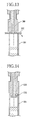
- However, as shown in Fig. 13, in the extracting apparatus of the Japanese Patent Laid-Open Publication No. 2005-110669, an
air nozzle 200 may be pressed against an extractingcartridge 201 in a state that a center axis of theair nozzle 200 is off to that of the extractingcartridge 201. In this state, aseal seat 202 cannot be uniformly pressed to the upper surface of the extractingcartridge 201 and the pressurized air may leak. Further, when theair nozzle 200 is pressed against the extractingcartridge 201 in the state that their center axes are off to each other, an upper portion of the extractingcartridge 201 may be deformed. As a result, the pressurized air may leak from a gap between theseal seat 202 and the upper surface of the extractingcartridge 201. - To solve the above problem, as shown in Fig. 14, an o-
ring 302 can be used, as a sealing member, which is pressed against the inner peripheral surface of the extractingcartridge 301 for sealing. With this method, a certain degree of the displacement of the center axis is corrected and the upper section of the extractingcartridge 301 can be securely sealed. However, since anair nozzle 300 tightly fits in the extractingcartridge 301 due to the elasticity of the o-ring 302, it becomes hard to separate theair nozzle 300 from the extractingcartridge 301 when theair nozzle 300 is retracted upward. Further, a portion of the air nozzle inserted into the extractingcartridge 301 is increased so that the liquid in the cartridge may adhere to the inserted portion. Accordingly, the contamination may occur. - An object of the present invention is to provide a pressurized air supplying mechanism, a pressurizing device and an extracting apparatus which can securely seal an inlet of a cartridge.
- Another object of the present invention is to provide a pressurized air supplying mechanism, a pressurizing device and an extracting apparatus for preventing a contamination of an air nozzle when the inlet of the cartridge is sealed.
- To achieve the above and other objects, a regulating section for preventing a displacement of the air nozzle in a diameter direction of the cartridge is provided in the air nozzle.
- In the pressurized air supplying mechanism of the present invention, a liquid is dispensed into an inlet of at least one of cartridges having a filter member and pressurized air is supplied to the cartridge through the inlet. The liquid is passed through the filter member and discharged from an outlet by applying the pressurized air.
- In a preferred embodiment, the pressurized air supplying mechanism comprises at least one air nozzle and an air nozzle moving section. The air nozzle includes an air outlet for discharging a pressurized air, a sealing member provided around the air outlet and pressed against the inlet of the cartridge and the regulating section provided at a lower end of the air outlet for preventing a displacement of the air nozzle in the diameter direction of the cartridge. The air nozzle moving section moves the air nozzle between a pressurizing position and a retracting position. In the pressurizing position, the air nozzle seals the inlet of the cartridge by pressing the sealing member against the inlet and supplies the pressurized air from the air outlet. In the retracting position, the air nozzle is retracted from the inlet of the cartridge.
- It is preferable that an outer diameter of the regulating section be slightly smaller than an inner diameter of the cartridge so as to fit in an inner peripheral surface of the cartridge. When the outer diameter of the regulating section is φA and the inner diameter of the cartridge is φa, it is preferable to satisfy φa-0.5mm ≤ φ A < φa. Further, it is more preferable to satisfy <φa-0.2mm ≤ φ A < φa. Chamfering is preferably applied to edges of the regulating section. Further, an inner diameter of the regulating section of the air nozzle may have approximately the same size as an outer diameter of the cartridge so as to fit in the outer peripheral surface of the cartridge. Furthermore, the positioning member of the air nozzle may have a shape which can be fit onto both the inner and the outer peripheral surfaces of the cartridge.
- The sealing member is an o-ring. A groove is curved in a diameter direction in the outer peripheral surface of the air nozzle. A width of the groove preferably increases in accordance with a depth of the groove. In particular, at least one of side walls of the groove is preferably inclined in a direction in which the width increases in accordance with the depth. It is also possible to incline both side walls of the groove. A distance between a lower end of the o-ring and a lower end of the regulating section is preferably 0.1mm or more. Further, the distance is preferably from 0.5mm to 1mm.
- When plural cartridges are used, a cartridge row is preferably formed by aligning the cartridges in at least one row in a first direction. The air nozzle moving section preferably includes a pressurizing head which retains the plural air nozzles corresponding to the cartridges in the cartridge row, and a pressurizing head moving section for moving the pressurizing head in an up-and-down direction between the pressurizing position and the retracting position.
- When the plural cartridges are connected in the row direction, the pressurizing head preferably retains each of the air nozzles in an independently movable manner in the up-and-down direction with the air nozzles biased downward to protrude at least one air nozzle in a position lower than the other air nozzles. The pressurizing head has a head main body for retaining each of the air nozzles independently in a movable manner in an up-and-down direction, a biasing member for biasing each of the air nozzles downward with respect to the head main body, a locking member for locking the other nozzles in a first position against the biasing force and for locking at least one air nozzle in a second position lower than the first position against the biasing force.
- The pressurizing device of the present invention comprises the pressurized air supplying mechanism, a cartridge holder for retaining the cartridge row in a second direction perpendicular to the first direction, and a moving section for moving the cartridge holder and the pressurizing head relative to the other in the second direction for supplying the pressurized air to each of the cartridge rows. The cartridge holder can be moved to the second direction. The pressurizing head can also be moved to the second direction with respect to the pressurizing head. Thereby, pressurizing processing can be performed to the plurality of cartridges in a short time.
- An extracting apparatus of the present invention includes the above pressurizing device and a dispensing device for dispensing the liquid into the cartridge having the filter member. The dispensing device dispenses the liquid into the cartridge having the filter member and the pressurizing device supplies the pressurized air to the cartridge to pass the liquid through the filter member. Thereby, a specific substance in the liquid is adsorbed to the filter member. A sample liquid including the specific substance, a washing liquid for washing off impurities other than the specific substance adhered onto the filter member and a recovery liquid for separating and recovering the specific substance adhered to the filter member are sequentially dispensed into the cartridge.
- In the pressurized air supplying mechanism of the pesent invention, since the air nozzle has the regulating section for preventing the displacement of the air nozzle in the diameter direction of the cartridge, the air nozzle is accurately positioned and pressed against the cartridge. Accordingly, the inlet of the cartridge is securely sealed.
- The outer diameter of the regulating section of the air nozzle is approximately the same as the inner diameter of the cartridge and fits in the inner peripheral surface. Or the inner diameter of the regulating section is approximately the same size as the outer diameter of the cartridge and fits on the outer peripheral surface of the cartridge. Thereby, deformation in an upper portion of the cartridge formed by resin is prevented and the inlet of the cartridge is securely sealed.
- The sealing member is an o-ring. The outer peripheral surface of the air nozzle has a groove in the diameter direction for fitting to the o-ring. A width of the groove increases as the depth of the groove increases. A force is exerted inward (toward the bottom of the groove in the diameter direction) in the pressurization and the o-ring never expands outward. Accordingly, the seal failure is prevented.
- The pressurizing head constituting the air nozzle moving section retains the air nozzles, each of which is biased downward but movable in the up-and-down directions. And at least one air nozzle protrudes in the position lower than the other air nozzles on the pressurizing head. Accordingly, when the pressurizing head is moved upward after the pressurized air is supplied, the air nozzles are separated from the cartridges except the one that protrudes, and then the this protruding air nozzle is separated from the cartridge. Thereby, each air nozzle can be securely separated from the cartridges connected to each other in the row direction.
- According to the pressurizing device of the present invention, the pressurizing processing can be performed to the plurality of the cartridges in a short time. Further, according to the extracting apparatus of the present invention, the extracting processing can be performed to a plurality of samples in a short time.
- The above objects and advantages of the present invention will become easily understood by one of ordinary skill in the art when the following detailed description would be read in connection with the accompanying drawings.
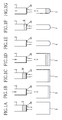
- Figs . 1A to 1G are explanatory views showing operations of nucleic acid extraction process;
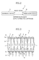
- Fig. 2 is an explanatory view which outlines an embodiment of a nucleic acid extraction apparatus of the present invention;
- Fig. 3 is an external view of an extracting cartridge unit;
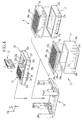
- Fig. 4 is an exploded perspective view of a cartridge holder, a waste liquid vessel and a recovery vessel;
- Fig. 5 is an external perspective view of a pressurizing device whose cover is removed;
- Fig. 6 is a block diagram showing an electrical configuration of the pressurizing device shown in Fig.5;
- Fig. 7 is a plan view showing a configuration of a head main body;
- Fig. 8 is a diagram of an air pressure circuit of the pressurizing device shown in Fig.5;
- Figs. 9A and 9B are explanatory views showing an movement of an air nozzle;
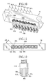
- Fig. 10 is an external perspective view showing another embodiment of the head main body;
- Fig. 11 is a bottom view showing another embodiment of the head main body;
- Fig. 12 is a section view showing another embodiment of a nozzle head;
- Fig. 13 is a section view showing conventional air nozzle and recovery vessel in the pressurizing operation; and
- Fig. 14 is a section view showing a conventional air nozzle with an o-ring and a conventional recovery vessel in the pressurization operation.
- Referring to Figs. 1A to 1G, a nucleic acid extraction processing is explained. First, as shown in Fig.1A, a sample liquid dispensing operation is performed in which a sample liquid S including dissolved nucleic acids is dispensed into an inlet of an extracting
cartridge 2. Next, as shown in Fig. 1B, a nucleic acid adsorption operation in which pressurized air is introduced to the extractingcartridge 2 above awaste liquid vessel 3 so that the sample liquid S passes through thefilter 2a and the nucleic acids are adsorbed onto thefilter 2a. A liquid component passed through thefilter 2a is discharged to thewaste liquid vessel 3 through an outlet of the extractingcartridge 2. - Thereafter, as shown in Fig. 1C, a washing liquid dispensing operation is performed in which a washing liquid W is dispensed into the extracting
cartridge 2. Next, as shown in Fig. 1D, a washing operation is performed in which the pressurized air is introduced to the extractingcartridge 2 to wash off and remove impurities while the nucleic acids are kept in thefilter 2a. The washing liquid W passed through thefilter 2a is discharged to thewaste liquid vessel 3. The washing liquid dispensing operation and the washing operation can be repeated plural times. - Thereafter, as shown in Fig. IE, the
waste liquid vessel 3 below the extractingcartridge 2 is replaced with a recovery vessel 4. Then, as shown in Fig. 1F, a recovery liquid dispensing operation is performed in which a recovery liquid R is dispensed into the extractingcartridge 2. Lastly, as shown in Fig. 1G, a nucleic acid recovery operation is performed in which the recovery liquid R including the nucleic acids are discharged to the recovering vessel 4 by introducing the pressurized air to the extractingcartridge 2 for pressurizing the extractingcartridge 2 so that the binding force between thefilter 2a and the nucleic acids is reduced to separate the adsorbed nucleic acids from thefilter 2a. - The
filter 2a is basically a porous filter through which the nucleic acids can be passed. A surface of thefilter 2a has a property to adsorb the nucleic acids contained in the sample liquid S by the chemical binding force. Thefilter 2a keeps the adsorption to the nucleic acids during the washing with the washing liquid W but reduces the adsorption force and separate the nucleic acids when the recovery liquid R is dispensed for recovering the nucleic acids. Such example is described in details in a separation and purification method of the nucleic acids disclosed in U.S. Patent Application Publication No. 2003/0170664 A1. In this document, thefilter 2a is formed of, for instance, an organic high polymer having a hydroxyl group on the surface. As the organic high polymer, an acetyl cellulose product with a saponified surface is preferable. As the acetyl cellulose, any of monoacetyl cellulose, diacetyl cellulose and triacetyl cellulose can be used, but the triacetyl cellulose is especially preferable. The surface of the acetyl cellulose is saponified by the saponification processing liquid (for instance, NaOH); however, the structure remains as the acetyl cellulose. An amount of the hydroxyl group (a density) on the surface can be controlled by a degree of surface saponification processing (a surface saponification degree). The adsorption effect to the nucleic acids is increased as the number of the hydroxyl groups are increased. For instance, when the triacetyl cellulose or the like is used, the surface saponification degree is preferably approximately 5% or more. The surface saponification degree is more preferably approximately 10% or more. As thefilter 2a, the porous membrane formed of the acetyl cellulose is suitable. - The sample liquid S including the nucleic acids is prepared by applying a pretreatment to a sample including cells or viruses. Pretreatment is a processing in which a water-soluble organic solvent is added to a solution dispersed with the nucleic acids in the liquid by the dissolution processing of the sample. For instance, in the field of medical diagnosis, the samples are solutions prepared from either of a bodily fluid such as whole blood, blood plasma, blood serum, urine, feces, semen, saliva and the like, and (a part of) a plant, (a part of) an animal, or a biological material such as a dissolved product or homogenates of these organisms. A dissolution processing is a treatment to the samples with using an aqueous solution including a reagent which dissolves the cell membrane and nuclear membrane to solubilize the nucleic acids. The reagent is a solution containing, for instance, a guanidine salt, a surface active agent and a protease. For instance, when the sample is the whole blood, red blood corpuscles and various proteins are decomposed and converted to low molecular weight substances in order for preventing nonspecific adsorption and clogging of the
filter 2a. In addition, white blood corpuscles and the nuclear membrane are dissolved to solubilize the nucleic acids to be extracted. As the water-soluble organic solvent, ethanol, isopropanol and propanol can be used, among which the ethanol is most preferable. A concentration of the water-soluble organic solvent is preferably 5-90 wt. %, and more preferably 20-60 wt.%. It is preferable to set the concentration of the ethanol as high as possible, without that the agglomerates are not generated. - The washing liquid W has a function to wash off impurities, included in the sample liquid S, which adhere to the
filter 2a along with the nucleic acids. The washing liquid W has a function to separate the impurities from thefilter 2a without breaking the adsorption of the nucleic acids to thefilter 2a. The washing liquid W is formed of the aqueous solution including a base compound and a buffer solution, and a surface active agent if necessary. As the base compound, the aqueous solution including approximately 10-100 wt. % (preferably 20-100 wt.%, more preferably 40-80 wt.%) of methanol, ethanol, isopropanol, N-isopropanol, butanol, acetone or the like is used. - The recovery liquid R is preferable to have a low salt concentration. It is preferable to use a solution which has the salt concentration of 0.5M or less such as, for instance, purified distilled water, TE buffer and the like.
- As shown in Fig.2, an exemplary nucleic
acid extracting apparatus 8 made according to the present invention is constituted of a dispensing device 9 and a pressurizingdevice 10. The dispensing device 9 and the pressurizingdevice 10 perform the extracting processing together while mutually transmitting and receiving the radio signals. In the nucleic extractingapparatus 8, an extracting cartridge unit 11 (see Fig.3), a cartridge holder 12 (see Fig.4), thewaste liquid vessel 3 and the recovery vessel 4 are loaded. - As shown in Fig. 3, the extracting
cartridge unit 11 is constituted of, for instance, eight extractingcartridges 2. The eight extractingcartridges 2 are arranged in a row and adjacent extractingcartridges 2 are connected by aconnector 2h. - The extracting
cartridge 2 has the following: a tubularmain body 2b, afilter 2a disposed at a bottom portion of the tubularmain body 2b, a discharge portion (an outlet) 2c protruded in a shape of a thin nozzle at a center area of the lower end of the tubularmain body 2b,positioning projections 2d having the flat exterior surfaces formed on the lateral surface of the tubularmain body 2b and astep portion 2e. On anupper end 2g of the tubularmain body 2b, an opening (an inlet) 2f is formed. When the plural extractingcartridge units 11 are arranged in plural columns, thepositioning projections 2d of the adjacent cartridges contact with each other so that the extractingcartridge units 11 are positioned in a direction perpendicular to the row direction. Further, the two extractingcartridges 2 placed on both ends of the extractingcartridge unit 11 have aside projection 7 respectively. - As shown in Fig. 4, the
cartridge holder 12 can hold the plural extractingcartridge units 11 in plural columns. Anopening 13 which is a through hole in an up-and-down direction is formed in thecartridge holder 12. The extractingcartridge units 11 are inserted in theopening 13. An inner peripheral surface of thecartridge holder 12 is formed as aguide wall 12a which guides the extractingcartridge unit 11 in the up-and-down direction (a Z-axis direction) while positioning the extractingcartridge unit 11 both in a forward-and-backward direction (an X-axis direction) and a right-and-left direction (a Y-axis direction). Eachguide wall 12a has an engagingportion 12b formed to protrude from theguide wall 12a. When the extractingcartridge unit 11 is inserted in thecartridge holder 12, the engagingportion 12b catches theside projection 7 to prevent the extractingcartridge unit 11 from slipping off from thecartridge holder 12. Thecartridge holder 12 holds plural extractingcartridge units 11 arranged in columns (12 columns in this embodiment). The extractingcartridges 2 are respectively arranged at constant pitches (9mm in this embodiment) both in the forward-and-backward direction and the right-and-left direction. Thecartridge holder 12 in which the plural extractingcartridge units 11 are set is mounted on a holder rack (not shown). - The
waste liquid vessel 3 is constituted of a vesselmain body 14 and apartition frame 15 fitted in an upper portion of the vesselmain body 14. The vesselmain body 14 has a rectangular box shape and has acontainer 14a which holds the waste liquid. Outer peripheries of anupper section 15a and alower section 15b of thepartition frame 15 are approximately the same size as the outer and inner periphery of the vesselmain body 14. When thepartition frame 15 is attached to the vesselmain body 14, thelower section 15b is inserted in thecontainer 14a, and theupper section 15a is mounted on an upper surface of the vesselmain body 14. In thepartition frame 15,cartridge mount holes 15c which are through-holes in the up-and-down direction with a rectangular section, are formed in a matrix arrangement. Thecartridge mount holes 15c are divided by thepartition plates 15d. The number of thecartridge mount holes 15c is formed to be equal to that of the extractingcartridges 2 which can be held by thecartridge holder 12. The pitch between thecartridge mount holes 15c corresponds to that between the extractingcartridges 2. Thewaste liquid vessel 3 is mounted on a waste liquid vessel rack (not shown). - The recovery vessel 4 is constituted of a vessel
main body 16 and asupport block 17 for supporting the vesselmain body 16. In the vesselmain body 16, a plurality ofrecovery tubes 16a with bottom is arranged in the matrix form. Eachrecovery tube 16a holds the recovery liquid discharged from the extractingcartridges 2. The number of therecovery tubes 16a is equal to that of the extractingcartridges 2 which can be held by thecartridge holder 12. The pitch between therecovery tubes 16a corresponds to that between the extractingcartridges 2. Thesupport block 17 supports the vesselmain body 16 at the same level as thewaste liquid vessel 3 with thepartition frame 15. Thereby, the top surfaces of thewaste liquid vessel 3 and the recovery vessel 4 will be level with each other when set in atransport mechanism 21. The recovery vessel 4 is mounted on the recovery vessel rack (not shown). - The dispensing apparatus 9 (see Fig. 2) has a function to perform the above-mentioned pretreatment to the sample to prepare the sample liquid S. Further, the dispensing apparatus 9 includes a dispensing mechanism (not shown) and a handling mechanism (not shown). The dispensing mechanism enables to dispense either of the sample liquid S, the
washing liquid 7 or the recovery liquid R at one time to the plural extracting cartridges held by thecartridge holder 12. The handling mechanism has a clamp for grasping thecartridge holder 12, thewaste liquid vessel 3 and the recovery vessel 4 and moves the clamp in the three dimensional directions to set thecartridge holder 12 and the like in thetransport mechanism 21 of the pressurizingdevice 10. A means for moving the clamp is constituted of a shifting mechanism for shifting the clamp in the three dimensional direction, an articulated robotic arm and the like. - As shown in Figs. 5 and 6, the pressurizing
device 10 includes thetransport mechanism 21 for moving the extractingcartridges 2, a pressurizedair supplying mechanism 22 for supplying the pressurized air to the extractingcartridges 2, amaintenance operation panel 23 and the like. The pressurizingdevice 10 is controlled by a system controller 24 (see Fig. 6) which will be described later. Thesystem controller 24 controls each section according to signals from a radio signal transmission/reception section 25 (see Fig. 6),maintenance operation panel 23 and the like. - The
transport mechanism 21 includes a table 29, atable support plate 30, a table motor 32 (see Fig. 6) andinspection block 33. The table 29 is fixed to thetable support plate 30 and has fourpillars 31 fixed to project upward on the upper surface thereof. Eachpillar 31 has an approximate L shape in horizontal section and is placed to face inward. Thetable support plate 30 is mounted on arail 28 extending in the forward-and-backward direction (the X-axis direction). The table 29 is moved along with thetable support plate 30 in the forward-and-backward direction when a drive force of thetable motor 32 is transferred. - On the table 29, one of the above-mentioned
waste liquid vessel 3 or the recovery vessel 4 is selectively placed. On an inner surface of the lower portion of eachpillar 31, apositioning guide 31a is protruded. Eachpositioning guide 31a has a tilted surface. When thewaste liquid vessel 3 is mounted on the table 29,lower corners 14b (see Fig. 4) of thewaste liquid vessel 3 are guided along the tilted surfaces so that thewaste liquid vessel 3 is positioned in the forward-and-backward direction (the X axis direction) and in the right-and-left direction (the Y axis direction). Mounted on the table 29, thewaste liquid vessel 3 is positioned in the up-and-down direction (the Z axis direction) . In the same manner, the recovery vessel 4 is set positioned in the forward-and-backward direction, the right-and-left direction and the up-and-down direction. - In an upper portion of each
pillar 31, astep 31b is formed. The above-mentionedcartridge holder 12 is mounted on thestep 31b. Thestep 31b has apositioning guide 31c protruded upward. Thepositioning guide 31c has a tilted surface. When thecartridge holder 12 is set on the table 29, thelower corners 12c (see Fig. 4) of thecartridge holder 12 are guided along the tilted surfaces of theguide 31c so that thecartridge holder 12 is positioned in the forward-and-backward direction (the X axis direction) and in the right-and-left direction (the Y axis direction). Thecartridge holder 12 is set positioned in the up-and-down direction (the Z axis direction) as it is mounted on thesteps 31b. - When the
cartridge holder 12 is mounted on the fourpillars 31 in a state that thewaste liquid vessel 3 is mounted on the table 29, thedischarge section 2c of the extractingcartridge 2 is inserted in an upper portion of thecartridge mount hole 15c of thewaste liquid vessel 3. The upper surface of thepartition plates 15d of thewaste liquid vessel 3 holds thestep section 2e of the extractingcartridge 2. Thereby, the extractingcartridge unit 11 is prevented from bending whenair nozzles cartridge unit 11. Further, when thecartridge holder 12 is mounted on the fourpillars 31 in a state that the recovery vessel 4 is mounted on the table 29, thedischarge section 2c of the extractingcartridge 2 is inserted in the upper portion of therecovery tube 16a of the recovery vessel 4. In the same manner as thewaste liquid vessel 3, the upper surface of the vesselmain body 16 of therecovery vessel 3 holds thestep section 2e of the extractingcartridge 2. - At the rear of the table 29 on the
table support 30, twosupport plates 34 are provided which are parallel in the forward-and-backward direction and in the up-and-down direction (that is, parallel in an XZ plane). The airleak detection block 33 is placed across upper parts of thesupport plates 34. The airleak detection block 33 is used for detecting whether sealing members at the air outlets of theair nozzles leak detection block 33,detection cavities 33a for air leak detection are formed with the number and pitch corresponding to those of the air nozzles. Thedetection cavities 33a respectively block the air outlets of the air nozzles when a later described pressurizinghead 40 moves down. The airleak detection block 33 moves along thetable support plate 30. Thereby, the airleak detection block 33 moves between a detecting position directly below theair nozzles leak detection block 33 is retracted from the detecting position. Note that the cavities are not necessarily formed on the airleak detection block 34 depending on configuration of air outlet of the air nozzles. For instance, the air leak detection block may have a flat contact surface. - As shown in Fig. 6, the
system controller 24 controls the rotation amount of thetable motor 32 based on the signals from atable position sensor 35 to control the moving amount of the table 29 (see Fig. 5) in the forward-and-backward direction. - The table 29 is sequentially positioned in the following positions: a loading position for mounting the
cartridge holder 12, thewaste liquid vessel 3 or the recovery vessel 4, a dispensing position for dispensing each liquid in the extractingcartridge 2, a detecting position in which the airleak detection block 33 is placed directly below theair nozzles cartridge unit 11 is placed directly below theair nozzles cartridge unit 11 is placed directly below theair nozzles cartridge unit 11 below the air nozzles. - Additionally, when the extracting
cartridge units 11 are set only in a part of thecartridge holder 12, it is not necessary to intermittently move the table 29 by the pitch between the extractingcartridges 2. The table 29 may be moved such that the set extractingcartridge units 11 are to be sequentially placed directly below theair nozzles - In the following, the pressurized
air supplying mechanism 22 is described. As shown in Fig. 5, the pressurizinghead 40 is provided in a front upper portion of themain body 10a. Theair nozzles head 40. Anair pump 42, twocondensation discharge valves throttle valve 45 and anair filter 70 are disposed in a lateral mid portion of themain body 10a. Plural open-close valves 46 are provided in a rear upper portion of themain body 10a. Inside the pressurizinghead 40, a relief valve 47 (see Figs. 6 and 8, pluralpressure release valves 48,plural pressure sensors 49 and apressure sensor 71 for therelief valve 47. Each component is properly connected through air tubes (not shown). In particular, the air tubes respectively connecting the open-close valves 46 and theair nozzles guide sleeves 53. The above components constitute the pressurizedair supplying mechanism 22. Each component of the pressurizedair supplying mechanism 22 is controlled by the system controller (see Fig. 6). - The pressurizing
head 40 is constituted of a headmain body 50 and abase block 52. The headmain body 50 is fixed to thebase block 52 with ascrew 51. Thebase block 52 is mounted on aguide rail 54 extending in up-and-down direction. Aball nut 55 is provided in thebase block 52, and aball screw 56 extending in the up-and-down direction is screwed into theball nut 55. A driving force of amotor 57 for the pressurizing head is transferred to theball screw 56 through a timing belt. When theball screw 56 is rotated, the base 52 moves up and down along theguide rail 54. Thus, the up-and-down mechanism of the pressurizinghead 40 is constituted. - The
air nozzles main body 50. As shown in Fig. 7, theair nozzle 41A is movable in the up-and-down direction with respect to the headmain body 50. Theair nozzle 41A is constituted of a nozzlemain body 80A, anozzle head 81A, acompression spring 82A, astopper 83A and aplug 84A. The nozzlemain body 80A is formed of a tube shape. Thenozzle head 81A is provided below the lower end portion of the nozzlemain body 80A. Thecompression spring 82A biases thenozzle head 81A toward the lower direction of the headmain body 50. Thestopper 83A blocks the movement of the nozzlemain body 80A toward the lower direction. Theplug 84A is provided in an upper end portion of the nozzlemain body 80A and connected to the air tube (not shown). - A
groove 85A is formed in an outer peripheral surface of thenozzle head 81A. An o-ring 86A is fitted in thegroove 85A. Hardness of the rubber used for forming the o-ring is determined as necessary. However, the hardness is preferably from 50 degrees to 70 degrees for practical use. An upper wall (a side wall of the groove) 88A is inclined toward the diameter direction, and a width (the up-and-down direction in the drawing) of thegroove 85A is enlarged as the groove becomes deeper. With this configuration, and the inward force at the time of pressurization, the o-ring 86A hardly extended outward and good air tightness will be maintained. A lower end portion (a regulating section) 87A of thenozzle head 81A is formed such that its outer diameter φA is approximately the same as or slightly smaller than an inner diameter φa of the extractingcartridge 2, and the corners of thelower end section 87A are chamfered. The outer diameter φA of thelower end section 87A is preferably within a range of " φa-0.5mm ≤ φ A< φa". The outer diameter is more preferably within "φa -0.2mm ≤φ A<φa" . A length L1 of thelower end portion 87A is preferably 0.1mm or more, and more preferably from 0.5mm to 1mm. Note that thelower end portion 87A fits in the inner peripheral surface of the extractingcartridge 2. On a lower end surface of thenozzle head 81A, anair outlet 89A which discharges the pressurized air is formed. - The
air nozzle 41B has the same configuration and the same size as those of theair nozzle 41A. Theair nozzle 41B is constituted of a nozzlemain body 80B, anozzle head 81B, acompression spring 82B, astopper 83B, and aplug 84B. Thenozzle head 81B has the same configuration and the size as those of thenozzle head 81A, and has agroove 85B, an o-ring 86B, a lower end section (a regulating section) 87B, an upper wall 88b and anair outlet 89B. - The
stopper 83A of theair nozzle 41A is fixed on anupper surface 50a of the headmain body 50. Thestopper 83B of theair nozzle 41B is fixed on alower surface 50c of arecess 50b formed in theupper surface 50a of the headmain body 50. Thereby, a position of theair nozzle 41B (a second position) is normally located lower than a position of theair nozzle 41A (a first position) . When a difference between these positions is defined as L2, it is preferable that the L2 is more than 0.5mm, and more preferable that the L2 is approximately 1mm. By displacing the position of theair nozzle 41B from those of theair nozzles 41A, theair nozzles cartridges 2 when retracting after the pressurization. - As shown in Fig. 6, the pressurizing
head motor 57 is controlled by thesystem controller 24. Thesystem controller 24 controls the rotation amount of the pressurizinghead motor 57 according to the signals from a pressurizinghead position sensor 59 to control the moving amount in the up-and-down direction of the headmain body 50. - As shown in Fig. 7, the head
main body 50 moves between the pressurizing position and the retracting position. In the pressurizing position in which the pressurized air is supplied, Theair nozzles main body 50 come in contact with theupper end 2g of the extractingcartridge 2 to seal theopening 2f in the airtight manner by the pressing force of the compression springs 82A and 82B. In the retracting position, theair nozzles upper end 2g of the extractingcartridge 2. Thus, the moving mechanism of theair nozzles head 40 and a moving mechanism for moving the pressurizinghead 40 in the up-and-down direction. Note that the moving mechanism of the air nozzle may have other configuration other than that of the above example as long as the moving mechanism will move the air nozzle between the pressurizing position and the retracting position. - In Fig. 8, each valve of the pressurizing device is turned off. A condensation discharge valve 43 (a three port solenoid valve in this example) is connected in the upstream of the
air pump 42. A condensation discharge valve 44 (a three port solenoid valve in this example) is connected in the downstream of theair pump 42. When the condensation is generated in the piping and becomes water droplets, the water droplets flow to the downstream and may wash off the nucleic acids adhered to thefilter 2a of thecartridge 2. Thecondensation discharge valves - The condensation discharging operation is performed in the following steps. First, the
relief valve 47 is turned on, and thecondensation discharge valves air pumps 42 are activated. Air passed through A, B and C areas is supplied to theair pump 42, and then the air passes through D area and discharged outside. Thereby, the condensation in the A and B areas are removed. The air also passes through the C and D areas. However, this air is bit too moist to remove the condensation in the C and D areas. Next, thecondensation discharge valve 43 is turned off, and thecondensation discharge valve 44 is remained on. A dry air from outside is supplied to theair pump 42 through the C area, and discharged outside through the D area. Thereby, the condensation is removed from the C and D areas. Lastly, thecondensation discharge valve 43 is turned on and thecondensation discharge valve 44 is turned off. The air passes from the B area through E areas. Thereby, the condensation in the E area is removed. Thereafter, thecondensation discharge valves air pump 42 is stopped. - In the downstream of the
condensation discharge valve 44, thethrottle valve 45 and theair filter 70 are provided. Thethrottle valve 45 adjusts the flow volume of the passing air to adjust the pressurizing speed of the pressurized air supplied to the downstream. Theair filter 70 removes the dust and the like in the pressurized air. - In the downstream of the
throttle valve 45, the plural (eight in this example) open-close valves (two-port solenoid valves in this example), thepressure sensor 50, and therelief valve 47 are connected. The open-close valve 46 blocks the pressurized air from the upstream when turned off, and passes the pressurized air when turned on. The open-close valve 46 is selectively turned on to supply the pressurized air in the downstream. Thepressure sensor 50 detects the pressure in the air passage to which thethrottle valve 45, the open-close valve 46 and therelief valve 47 are connected. Therelief valve 47 is turned on when the pressure in the air passage excesses the predetermined value due to the continuous driving of theair pump 42. Thereby, the pressurized air in the air passage is discharged outside. - In the downstream of the open-
close valve 46, the pressure release valve 48 (a three-port solenoid valve in this example) is connected. Thepressure release valve 48 blocks the pressurized air from the upstream. Thepressure release valve 48 can be turned on and off. In an OFF position, the downstream is opened to the atmosphere. In an ON position, the pressurized air from the upstream is passed to the downstream. - In the downstream of each of the
pressure release valves 48, theair nozzle pressure sensors 49 are respectively connected to the air passages. Thepressure sensor 49 detects the pressure inside the air passage which connects thepressure release valve 48 and theair nozzle cartridge 2 pressed by theair nozzle - The
system controller 24 controls each valve according to the detected pressure. To be specific, when the detected pressure reaches the maximum value for the pressurization while the pressurized air is supplied to the air nozzle with the open-close valve 46 and thepressure release valve 48 turned on, the open-close valve 46 is turned off to make the air nozzle and the extractingcartridge 2 airtight. While keeping the air nozzle and the extractingcartridge 2 airtight, when it is determined that the liquid in the extractingcartridge 2 is completely discharged according to the change in the detected pressure, thepressure release valve 48 is turned off and the air nozzle and the extractingcartridge 2 are opened to the atmosphere. Note that the pressurized air within a predetermined pressure range (for instance, from 30kPa to 200kPa, more preferably from 50kPa to 150kPa) is preferably supplied. - Further, the
system controller 24 also detects whether the extractingcartridges 2 are set in thecartridge holder 12 or not, the presence or absence of (each) liquid, a shortage of the liquid, clogging of the filter, and the like. - As shown in Fig. 5, the
maintenance operation panel 23 is operated at the time of maintenance, and includes adisplay section 60 and an operationkey unit 61. When the operationkey unit 61 is operated, the operation signal is sent to thesystem controller 24 so that each section can be driven according to the operation. - Below the
maintenance operation panel 23, amemory card slot 62 is provided. At the back of thememory card slot 62, a card reader is incorporated. The card reader electrically accesses to thememory card 63 and reads and writes the data. In thememory card 63, a communication information with the dispensing device 9 and a processing information of the extraction processing are written. - Hereinafter, an operation of the above configuration is described. When the powers of the dispensing device 9 and the pressurizing
device 10 are respectively turned on, the dispensing device 9 performs the preparation operation. Upon receiving the preparation completion signal from the dispensing device 9, the pressurizingdevice 10 performs the preparation operation. - The pressurizing
device 10 performs the air leak detection when the preparation operation is completed. The table 29 is moved to the detecting position and moves the airleak detection block 33 directly below theair nozzles air nozzles air outlets air nozzles rings rings display section 60 of themaintenance operation panel 23. After a predetermined time, the pressurizinghead 40 is moved upward and theair nozzles - In this embodiment, the detecting position, the mount position and the dispensing position of the table 29 are in the same position. Further, the above position is set as an initial position of the table 29.
- The pressurizing
device 10 transmits the signal notifying the completion of the air leak detection. A handling mechanism of the dispensing device 9 grasps thewaste liquid vessel 3 and mounts thewaste liquid vessel 3 on the table 29. Then, the handling mechanism grasps thecartridge holder 12 in whichplural cartridge units 11 are aligned and mounts thecartridge holder 12 on the table 29. Thereafter, the dispensing mechanism of the dispensing device 9 dispenses the sample liquid S in each of the extractingcartridges 2 of the extractingcartridge unit 11. - The pressurizing
device 10 starts the pressurizing operation (the nucleic acid adsorption operation) upon receiving the signal notifying the completion of the sample liquid dispensing operation. The table 29 moves to the pressurization start position in which the first row of the extractingcartridge units 11 is placed directly below theair nozzles - When the pressurizing
head 40 is moved downward, theair nozzle 41B comes in contact with the corresponding extractingcartridge 2 through the o-ring 86B. Then theair nozzle 41A comes in contact with the corresponding extractingcartridge 2 through the o-ring 86A. In this time, the lower end portions (the regulating portions) 87A and 87B are respectively guided and fit in the upper portions of the inner peripheral surfaces of the corresponding extractingcartridges 2. Thereby, even when the central axes of theair nozzles cartridges 2, such displacements are corrected andair nozzles - As shown in Fig. 9A, when the pressurizing
head 40 is further moved downward, theair nozzles cartridges 2 through the o-rings air nozzles air pump 42 is driven in a state that all the open-close valves 46 are turned off and all thepressure release valves 48 are turned on. - The first (the leftmost) open-
close valve 46 is turned on and the pressurized air is supplied to the corresponding extractingcartridge 2. When the pressure sensor checks that the pressure reaches the predetermined value, the first open-close valve 46 is turned off. Then, the second open-close valve 46 is turned on and the pressurized air is supplied to the corresponding extractingcartridge 2. The operation is performed to all the extractingcartridges 2 in the first row of thecartridge holder 12. The sample liquid S passes through thefilter 2a and the nucleic acids are adhered to thefilter 2a. Other liquid components are discharged to thewaste liquid vessel 3. When the whole sample liquid S passes through thefilter 2a and the pressure is decreased, thepressure release valve 48 is turned off. Note that the inserted portions of theair nozzles cartridges 2 are very small, so the liquids do not adhere to the inserted portions. Accordingly, the contaminations are not generated. - When all the
pressure release valves 48 are turned off, thepressure head 40 moves upward. As shown in Fig.9B, first, sevenair nozzles 41A are separated from the corresponding extractingcartridges 2. Next, oneair nozzle 41B is separated from the corresponding extractingcartridge 2. When theair nozzles 41A are separated, sincelower end portions 87A of theair nozzles 41A are fitted in the corresponding extractingcartridges 2, the extractingcartridge unit 11 is likely to move upward along with theair nozzles 41A by a fitting force of sevenlower end portions 87A. However, since the extractingcartridge unit 11 is pressed by theair nozzle 41B, theair nozzles 41A easily separate from the extractingcartridges 2. When theair nozzle 41B is separated, thelower end portion 87B of theair nozzle 41B fits in the inner peripheral surface of the corresponding extractingcartridge 2. However, a fitting force of onelower end portion 87B is weak and theair nozzle 41B easily separates from the corresponding extractingcartridge 2. When the pressurizinghead 40 further moves upward, theair nozzles pressure release valves 48 are turned on again. - When the pressurizing operation of the first row of the extracting
cartridges 2 is completed, the table 29 moves toward the back by the pitch of the extractingcartridge 2. The second row of the extractingcartridges 2 is placed directly below theair nozzles air nozzles air nozzles - The pressurizing
device 10 transmits the signal to notify the completion of the pressurizing operation (the nucleic acid adsorption operation) to the dispensing device 9. Then, the dispensing mechanism of the dispensing device 9 dispenses the washing liquid W into the extractingcartridges 2 at one time. - When the pressurizing
device 10 receives the signal to notify the completion of the washing liquid dispensing operation from the dispensing device 9, the pressurizing operation (washing operation) is started. The table 29 moves to the pressurizing start position. The pressurizing operation of the washing liquid W is performed in the same manner as that of the sample liquid S. The washing liquid W passed through thefilter 2a is discharged to thewaste liquid vessel 3 with the impurities other than nucleic acids. After the pressurizing operation is performed to all the rows, the table 29 is returned to the initial position. - The pressurizing
device 10 transmits the signal to notify the completion of the pressurizing operation (washing operation) to the dispensing device 9. The handling mechanism of the dispensing device 9 holds thecartridge holder 12 and temporarily puts thecartridge holder 12 on the holder rack. Next, the handling mechanism holds thewaste liquid vessel 3 and puts thewaste liquid vessel 3 on the waste liquid vessel rack. Thereafter, the handling mechanism holds the recovery vessel 4 in the recovery vessel rack and mounts it on the table 29 of the pressurizingdevice 10. Thereafter, the handling mechanism holds thecartridge holder 12 in the holder rack and mounts thecartridge holder 12 on the table 29. The dispensing mechanism of the dispensing device 9 dispenses the recovery liquid R into the extractingcartridges 2 at one time. - Upon receiving the signal to notify the completion of the recovery liquid dispensing operation from the dispensing device 9, the pressurizing
device 10 starts the pressurizing operation (nucleic acid recovery operation). The table 29 moves to the pressurization start position. The pressurizing operation to the recovery liquid R is performed in the same manner as those of the sample liquid A and the washing liquid W. The recovery liquid R passes through thefilter 2a to the corresponding recovery tube in the recovery vessel 4 together with the nucleic acids which have been adsorbed to thefilter 2a. - The pressurizing
device 10 transmits the signal notifying the completion of the pressurizing operation (nucleic acid recovery operation) to the dispensing device 9. The handling mechanism of the dispensing device 9 holds thecartridge holder 12 and puts it in the holder rack, and then holds therecovery vessel 3 to put it in the recovery vessel rack. The recovery liquids in therecovery tubes 16a in therecovery vessel 3 are analyzed by another device. The used extracting cartridges in thecartridge holder 12 are discarded. - When the pressurizing
device 10 receives the signal from the dispensing device 9 notifying therecovery vessel 3 is accommodated, the condensation discharging operation is performed in which the condensation in the piping of the pressurizedair supplying mechanism 22 is removed. The operation can be performed at any suitable timing but not to interfere the extracting operation. The operation can be performed, for instance, between the nucleic acid adsorbing operation and the washing operation. After the condensation discharging operation, if the extracting operation is to be continued, above-mentioned extracting operation is repeated in sequence using another cartridge holder holding new extracting cartridges and a new recovery vessel. - According to the above embodiment, the extracting cartridge unit in which plural extracting cartridges are connected is used. Accordingly, it becomes easy to handle a plurality of extracting cartridges. The process for setting the extracting cartridges in the cartridge holder is facilitated.
- According to the above embodiment, the pressurization processing can be performed to the plurality of extracting cartridges in a short time. Further, the liquid can be dispensed into the plurality of extracting cartridges in a short time. Thereby, the extracting processing to a multitude of samples can be performed in a short time.
- In the above embodiment, a part of the air nozzle is fit in the inner peripheral surface of the extracting cartridge for positioning the air nozzle. In addition, a part of the air nozzle can be fit onto the outer peripheral surface of the extracting cartridge. As shown in Figs. 10 and 11,
air nozzles 141A and 141B havingpositioning frames air nozzles 141A and 141B are securely positioned by fitting theair nozzles 141A and 141B in the inner peripheral surface and the outer peripheral surface of the extracting cartridges. Note that it is also possible to provide only the positioning frames 100A and 100B without providinglower end sections - In the above embodiment, when the groove for fitting to the 0-ring is formed in the outer periphery of the nozzle head, the width (the width in the up-and-down direction) of the groove is increased as the groove becomes deeper by inclining the upper wall. However, as shown in Fig. 12, a
nozzle head 181A whoselower wall 101A is inclined can be used. Further, as long as the width of the groove increases as the groove becomes deeper, the groove is not limited to the above shape and can be of any arbitrary shape. - In the above embodiment, one air nozzle is protruded downward among eight air nozzles, but any arbitrary number of nozzles can be protruded downward. However, it is preferable to protrude few air nozzles, for instance, one to three air nozzles. In the above embodiment, a fourth air nozzle from the left among the eight air nozzles is protruded downward. However, any air nozzle can be protruded downward. However, it is preferable to protrude the air nozzle placed close to the center portion. In the above embodiment, the air nozzles are held in either of the first or second positions. However, it is also possible to add, for instance, a third position to hold the air nozzle. In this case, the air nozzles placed closer to the center should contact to the cartridges at lower position. Accordingly, the air nozzle is more securely separated from the extracting cartridge.
- The above embodiment is described in a state that the air nozzles are arranged in one row. However, the air nozzles can be arranged in plural rows. In that case, the table is moved according to the number of the nozzles rows. For instance, when the air nozzles are arranged in three rows, the table is moved by the amount which is three times longer as the pitch between the extracting cartridges (27mm in the above example).
- In the above embodiment, eight extracting cartridges constitute the extracting cartridge unit. However, any arbitrary number of cartridges can be used for forming the extracting cartridge unit. Further, it is also possible to use the extracting cartridge unit in the matrix arrangement in which plural rows of extracting cartridges are connected with each other.
- In the above embodiment, the cartridge holder is capable of holding 12 rows of the extracting cartridges. However, the number of rows can be set arbitrarily. Further, by adopting an endless loading mechanism, more numbers of the extracting cartridges can be handled.
- In the above embodiment, the cartridge holder is moved to the forward-and-backward direction with respect to the air nozzle. However, it is also possible to fix the cartridge holder and move the air nozzle in the forward-and-backward direction with respect to the cartridge holder.
- In the above embodiment, pressurization is used as a means to apply an external force to each liquid for passing the liquid through the filter. However, depressurization can be used instead.
- An individual identifying element, for instance, an IC tag (an IC chip) which enables to identify each unit or each cartridge may be attached to each extracting cartridge unit or each extracting cartridge. Each extracting cartridge unit or each extracting cartridge can be controlled according to the individual identification element.
- In the above embodiment, the washing operation is performed using the washing liquid. However, washing processing may not be necessary according to a permeability of the filter member. In the above embodiment, the recovery operation is performed using the recovery liquid. However, the recovery liquid is not necessarily used. For instance, it is possible to analyze the specific substance as it adsorbs to the filter member.
- In the above embodiment, the nucleic acid extraction apparatus is described. However, the present invention is not limited to this and can also be applied for adsorption of various specific substances to the filter member.
- In the above embodiment, the nucleic extracting apparatus is constituted of the dispensing device and the pressurizing device which are separately formed. Instead, the dispensing device and the pressurizing device are integrally formed such as one disclosed in the Japanese Patent Laid-Open Publication No. 2005-110669.
- Various changes and modifications are possible in the present invention and may be understood to be within the present invention.
Claims (20)
- A pressurized air supplying mechanism (22) which supplies pressurized air through an inlet (2f) of at least one of cartridges (2) each having a filter member (2a) after a liquid is dispensed into said cartridge through said inlet, said pressurized air allowing said liquid to pass through said filter member and leave from an outlet of said cartridge, said pressurized air supplying mechanism comprising:at least one air nozzle (41A) including an air outlet (89A) for discharging said pressurized air, a sealing member (86A) provided around said air outlet, for pressing against said inlet of said cartridge, and a regulating section (87A) provided at a lower end of said air outlet for preventing a displacement of said nozzle in a diameter direction of said cartridge; andan air nozzle moving section for moving said air nozzle between a pressurizing position at which said air nozzle is pressed against said inlet of said cartridge through said sealing member to seal said inlet in an airtight manner, and a retracting position at which said air nozzle is retracted from said inlet of said cartridge.
- A pressurized air supplying mechanism according to claim 1, wherein an outer diameter of said regulating section is slightly smaller than an inner diameter of said cartridge such that said regulating section fits in an inner peripheral surface of said cartridge.
- A pressurized air supplying mechanism according to claim 2, wherein φ a-0. 5mm ≤ φ A< φa is satisfied when said outer diameter of said regulating section is φA and said inner diameter of said cartridge is ϕa.
- A pressurized air supplying mechanism according to claim 2, wherein φ a-0.2mm ≤ φ A< φ a is satisfied when said outer diameter of said regulating section is φA and said inner diameter of said cartridge is φa.
- A pressurized air supplying mechanism according to claim 2, wherein an edge of said regulating section is chamfered.
- A pressurized air supplying mechanism according to claim 1, wherein an inner diameter of said regulating section is approximately the same as an outer diameter of said cartridge, and said regulating section fits onto an outer peripheral surface of said cartridge.
- A pressurized air supplying mechanism according to claim 1, wherein said sealing member is an o-ring, a groove (85A) for fitting to said o-ring is formed in said outer peripheral surface of said air nozzle, said groove curving in a diameter direction of said air nozzle, a width of said groove increasing in accordance with a depth of said groove.
- A pressurized air supplying mechanism according to claim 7, wherein at least one of two side walls of said groove is inclined such that said width is increased as said depth is increased.
- A pressurized air supplying mechanism according to claim 7, a distance between a lower end of said o-ring and a lower end of said regulating section is 0.1mm or more.
- A pressurized air supplying mechanism according to claim 7, a distance between a lower end of said o-ring and a lower end of said regulating section ranges from 0.5mm to 1mm.
- A pressurized air supplying mechanism according to claim 1, wherein said cartridges are aligned in at least one row in a first direction to form a cartridge row, and wherein said air nozzle moving section has a pressurizing head (40) which retains said air nozzles corresponding to said cartridges in said cartridge row, and a pressurizing head moving section for moving said pressurizing head in an up-and-down direction between said pressurizing position and said retracting position.
- A pressurized air supplying mechanism according to claim 11, wherein said pressurizing head retains each of said air nozzles in an independently movable manner in said up-and-down direction with said air nozzles biased downward, and said pressurizing head retains at least one air nozzle to protrude in a position lower than the other nozzles.
- A pressurized air supplying mechanism according to claim 12, wherein said pressurizing head including:a head main body for retaining each of said air nozzles in an independently movable manner in an up-and-down direction;a biasing member (82A) for biasing each of said air nozzles downward with respect to said head main body;a locking member (83A) for locking said other nozzles in a first position against biasing force of said biasing member, and for locking said at least one air nozzle in a second position lower than said first position against said biasing force.
- A pressurizing device (10) for pressurizing a liquid dispensed from an inlet (2f) of a cartridge (2) by supplying a pressurized air from said cartridge so as to pass said liquid through a filter member (2a) in said cartridge, said pressurizing device comprising:a cartridge holder (12) for retaining plural cartridge rows, each of said cartridge rows having N numbers of said cartridges being aligned in a first direction in each of said cartridge rows;an air nozzle row in which N numbers of air nozzles (41A) are aligned in said first direction, said N numbers of air nozzles corresponding to N numbers of said cartridges forming said cartridge row, each of said air nozzles including an air outlet (89A) for discharging said pressurizing air, a sealing member (86A) to be pressed against said inlet of said cartridge and a regulating section (87A) provided at a lower end of said air outlet for preventing a displacement of said air nozzle in a diameter direction of said cartridge;a pressurizing head (40) for retaining said air nozzle row;a pressurizing head moving mechanism for moving said pressurizing head in an up-and-down direction between a pressurizing position and a retracting position, each of said air nozzles being pressed against said inlet of said cartridge through said sealing member to seal said inlet in an airtight manner for supplying pressurized air from said air outlet in said pressurizing position, and said air nozzle being retracted from said cartridge in said retracting position; anda moving mechanism for moving one of said pressurizing head or said cartridge holder relative to the other in a second direction perpendicular to said first direction.
- A pressurizing device according to claim 14, wherein said pressurizing head retains each of said air nozzles in an independently movable manner in an up-and-down direction, said pressurizing head retains at least one air nozzle (41B) to protrude in a position lower than the other nozzles.
- A pressurizing device according to claim 14, wherein said pressurizing head including:a head main body for retaining each of said air nozzles in an independently movable manner in an up-and-down direction;a biasing member (82A) for biasing each of said air nozzles downward with respect to said head main body; anda locking member (83A) for locking said other air nozzles in a first position against biasing force of said biasing member, and for locking said at least one air nozzle in a second position lower than said first position against said biasing force.
- An extracting apparatus for adsorbing a specific substance through a filter member (2a) in a cartridge (2) when_a liquid passes through said filter member, said liquid being dispensed through an inlet (2f) of said cartridge and pressurized to pass through said filter member by a pressurized air supplied from said inlet, said extracting apparatus comprising:a cartridge holder (12) for retaining plural cartridge rows, each of said cartridge rows having N numbers of said cartridges being in a first direction in each of said cartridge rows;a dispensing device for dispensing said liquid in said N numbers of said cartridges;an air nozzle row in which N numbers of air nozzles (41A) are aligned in said first direction, said N numbers of air nozzles (41A) corresponding to N numbers of said cartridges forming one cartridge row, each of said air nozzles including an air outlet for discharging said pressurized air, a sealing member (86A) provided around said air outlet and pressed against said inlet of said cartridge and a regulating section (87A) provided at a lower end of said air outlet for preventing a displacement of said air nozzle in a diameter direction of said cartridge;a pressurizing head (40) for retaining said air nozzle row;a pressurizing head moving mechanism for moving said pressurizing head in an up-and-down direction between a pressurizing position and a retracting position, each air nozzle being pressed against said inlet of said cartridge through said sealing member to seal said inlet in an airtight manner for supplying a pressurized air from said air outlet in said pressurizing position, and said air nozzle being retracted from said cartridge in said retracting position;a moving mechanism for moving one of said pressurizing head or said cartridge holder relative to the other in a second direction perpendicular to said first direction.
- An extracting apparatus according to claim 17, wherein said pressurizing head retains each of said air nozzles in an independently movable manner in an up-and-down direction with said air nozzles biased downward, and said pressurizing head retains at least one air nozzle (41B) to protrude in a position lower than the other nozzles.
- An extracting apparatus according to claim 17, wherein said pressurizing head including:a head main body for retaining each of said air nozzles in an independently movable manner in an up-and-down direction;a biasing member (82A) for biasing each of said air nozzles downward with respect to said head main body; anda locking member (83A) for locking said other air nozzles in a first position against biasing force of said biasing member, and for locking said at least one air nozzle (41B) in a second position lower than said first position against said biasing force.
- An extracting apparatus according to claim 17, wherein said liquid dispensed into said cartridge is at least one of a sample liquid including a specific substance, a washing liquid for washing off impurities other than said specific substance adhered to said filter member and a recovery liquid for separating and recovering said specific substance adhered to said filter member.
Applications Claiming Priority (1)
| Application Number | Priority Date | Filing Date | Title |
|---|---|---|---|
| JP2005012989A JP2006198523A (en) | 2005-01-20 | 2005-01-20 | Pressurized air feed mechanism, pressure device, and extractor |
Publications (3)
| Publication Number | Publication Date |
|---|---|
| EP1683577A2 true EP1683577A2 (en) | 2006-07-26 |
| EP1683577A3 EP1683577A3 (en) | 2006-08-02 |
| EP1683577B1 EP1683577B1 (en) | 2009-09-16 |
Family
ID=35911125
Family Applications (1)
| Application Number | Title | Priority Date | Filing Date |
|---|---|---|---|
| EP06001127A Ceased EP1683577B1 (en) | 2005-01-20 | 2006-01-19 | Pressurized air supplying mechanism, pressurizing device and extracting apparatus |
Country Status (4)
| Country | Link |
|---|---|
| US (1) | US20060159593A1 (en) |
| EP (1) | EP1683577B1 (en) |
| JP (1) | JP2006198523A (en) |
| DE (1) | DE602006009158D1 (en) |
Cited By (1)
| Publication number | Priority date | Publication date | Assignee | Title |
|---|---|---|---|---|
| LU501940B1 (en) * | 2022-04-26 | 2023-10-26 | Dispendix Gmbh | Method for determining a leak in a dispensing device for dispensing liquid |
Families Citing this family (5)
| Publication number | Priority date | Publication date | Assignee | Title |
|---|---|---|---|---|
| US7915030B2 (en) * | 2005-09-01 | 2011-03-29 | Canon U.S. Life Sciences, Inc. | Method and molecular diagnostic device for detection, analysis and identification of genomic DNA |
| EP2607904B1 (en) | 2011-12-21 | 2020-01-15 | Roche Diagnostics GmbH | Method for disposing of a liquid within an automated analytical system, tip rack assembly and analytical system |
| DE102017002046A1 (en) * | 2017-03-03 | 2018-09-06 | aquila biolabs GmbH | Method and device for metering and storing liquids by means of permanently open containers |
| US12059645B1 (en) * | 2020-05-08 | 2024-08-13 | 10X Genomics, Inc. | Condensation removal from compressed gas systems |
| CN113075022B (en) * | 2021-03-22 | 2022-11-22 | 山东宗德机电设备有限公司 | High-temperature hardness tester for continuous high-temperature hardness test |
Family Cites Families (10)
| Publication number | Priority date | Publication date | Assignee | Title |
|---|---|---|---|---|
| US3370508A (en) * | 1966-01-10 | 1968-02-27 | Joseph A. Iaia | Method for establishing o-ring seal grooves |
| DE2545997C3 (en) * | 1975-10-14 | 1978-09-07 | Max-Planck-Gesellschaft Zur Foerderung Der Wissenschaften E.V., 3400 Goettingen | Device for multiple column chromatography |
| DE3143075A1 (en) * | 1981-10-30 | 1983-05-11 | Merck Patent Gmbh, 6100 Darmstadt | COLUMN CLAMPING DEVICE FOR CHROMATOGRAPHY " |
| US4948564A (en) * | 1986-10-28 | 1990-08-14 | Costar Corporation | Multi-well filter strip and composite assemblies |
| US5601785A (en) * | 1991-12-23 | 1997-02-11 | Microsensor Technology, Inc. | Connector for detachable column cartridge for gas chromatograph |
| US6171555B1 (en) * | 1995-04-17 | 2001-01-09 | Ontogen Corporation | Reaction block docking station |
| JP2832586B2 (en) * | 1995-08-04 | 1998-12-09 | 株式会社トミー精工 | DNA extraction and purification method |
| DE19835833A1 (en) * | 1998-08-07 | 2000-02-17 | Max Planck Gesellschaft | Dosing head for parallel processing of a large number of fluid samples |
| JP3580801B2 (en) * | 2001-08-01 | 2004-10-27 | 富士写真フイルム株式会社 | Methods for separating and purifying nucleic acids |
| JP4522800B2 (en) * | 2003-09-19 | 2010-08-11 | 富士フイルム株式会社 | Extraction device |
-
2005
- 2005-01-20 JP JP2005012989A patent/JP2006198523A/en active Pending
-
2006
- 2006-01-19 DE DE602006009158T patent/DE602006009158D1/en not_active Expired - Lifetime
- 2006-01-19 EP EP06001127A patent/EP1683577B1/en not_active Ceased
- 2006-01-20 US US11/335,478 patent/US20060159593A1/en not_active Abandoned
Cited By (1)
| Publication number | Priority date | Publication date | Assignee | Title |
|---|---|---|---|---|
| LU501940B1 (en) * | 2022-04-26 | 2023-10-26 | Dispendix Gmbh | Method for determining a leak in a dispensing device for dispensing liquid |
Also Published As
| Publication number | Publication date |
|---|---|
| JP2006198523A (en) | 2006-08-03 |
| US20060159593A1 (en) | 2006-07-20 |
| EP1683577A3 (en) | 2006-08-02 |
| EP1683577B1 (en) | 2009-09-16 |
| DE602006009158D1 (en) | 2009-10-29 |
Similar Documents
| Publication | Publication Date | Title |
|---|---|---|
| US12128407B2 (en) | Microfluidic chips and cartridges and systems utilizing microfluidic chips and cartridges | |
| KR20110121588A (en) | Automatic biological sample purification device equipped with magnetic field applying unit, method of extracting target substance from biological sample and method of protein expression and purification | |
| US20200377845A1 (en) | Nucleic acid separating apparatus | |
| JPWO2008096776A1 (en) | Container repeated use magnetic particle parallel processing apparatus and container repeated use magnetic particle parallel processing method | |
| US7326386B2 (en) | Apparatus for extracting nucleic acid | |
| US7025876B2 (en) | Sample processing device and sample processing method | |
| EP1683577B1 (en) | Pressurized air supplying mechanism, pressurizing device and extracting apparatus | |
| US7811758B2 (en) | Method and apparatus of automatically isolating and purifying nucleic acid | |
| US7354510B2 (en) | Extracting apparatus | |
| JP2008086893A (en) | Porous filter cartridge and manufacturing method thereof | |
| JP4478588B2 (en) | Specific substance recovery apparatus and nucleic acid extraction apparatus using the same | |
| US20050042146A1 (en) | Rack for extracting apparatuses | |
| JP2005204578A (en) | Extraction device | |
| JP2005058149A (en) | Apparatus for extracting nucleic acid | |
| JP2006197850A (en) | Pressurizing device and extracting apparatus | |
| JP3635645B1 (en) | Nucleic acid extraction equipment | |
| JP2005328730A (en) | Nucleic acid extraction equipment | |
| JP2006197851A (en) | Vessel for extraction and extractor | |
| JP4522800B2 (en) | Extraction device | |
| JP2006198524A (en) | Apparatus for supplying compressed air and extractor | |
| JP2007252336A (en) | Pressurization device for extraction cartridge | |
| JP2005278436A (en) | Automatic nucleic acid isolating/refining system | |
| JP2007252334A (en) | rack | |
| JP2007252338A (en) | Pressurization device for extraction cartridge | |
| JP2007252337A (en) | Pressurization device for extraction cartridge |
Legal Events
| Date | Code | Title | Description |
|---|---|---|---|
| PUAI | Public reference made under article 153(3) epc to a published international application that has entered the european phase |
Free format text: ORIGINAL CODE: 0009012 |
|
| PUAL | Search report despatched |
Free format text: ORIGINAL CODE: 0009013 |
|
| AK | Designated contracting states |
Kind code of ref document: A2 Designated state(s): AT BE BG CH CY CZ DE DK EE ES FI FR GB GR HU IE IS IT LI LT LU LV MC NL PL PT RO SE SI SK TR |
|
| AX | Request for extension of the european patent |
Extension state: AL BA HR MK YU |
|
| AK | Designated contracting states |
Kind code of ref document: A3 Designated state(s): AT BE BG CH CY CZ DE DK EE ES FI FR GB GR HU IE IS IT LI LT LU LV MC NL PL PT RO SE SI SK TR |
|
| AX | Request for extension of the european patent |
Extension state: AL BA HR MK YU |
|
| RIC1 | Information provided on ipc code assigned before grant |
Ipc: B01L 3/02 20060101ALI20060623BHEP Ipc: B01D 29/52 20060101ALI20060623BHEP Ipc: G01N 35/10 20060101ALI20060623BHEP Ipc: F16J 15/32 20060101ALI20060623BHEP Ipc: B01L 3/00 20060101AFI20060310BHEP Ipc: B01D 29/00 20060101ALI20060623BHEP |
|
| 17P | Request for examination filed |
Effective date: 20070201 |
|
| RAP1 | Party data changed (applicant data changed or rights of an application transferred) |
Owner name: FUJIFILM CORPORATION |
|
| 17Q | First examination report despatched |
Effective date: 20070302 |
|
| AKX | Designation fees paid |
Designated state(s): DE FR GB SE |
|
| GRAP | Despatch of communication of intention to grant a patent |
Free format text: ORIGINAL CODE: EPIDOSNIGR1 |
|
| GRAS | Grant fee paid |
Free format text: ORIGINAL CODE: EPIDOSNIGR3 |
|
| GRAA | (expected) grant |
Free format text: ORIGINAL CODE: 0009210 |
|
| AK | Designated contracting states |
Kind code of ref document: B1 Designated state(s): DE FR GB SE |
|
| REG | Reference to a national code |
Ref country code: GB Ref legal event code: FG4D |
|
| REF | Corresponds to: |
Ref document number: 602006009158 Country of ref document: DE Date of ref document: 20091029 Kind code of ref document: P |
|
| PG25 | Lapsed in a contracting state [announced via postgrant information from national office to epo] |
Ref country code: SE Free format text: LAPSE BECAUSE OF FAILURE TO SUBMIT A TRANSLATION OF THE DESCRIPTION OR TO PAY THE FEE WITHIN THE PRESCRIBED TIME-LIMIT Effective date: 20090916 |
|
| PLBE | No opposition filed within time limit |
Free format text: ORIGINAL CODE: 0009261 |
|
| STAA | Information on the status of an ep patent application or granted ep patent |
Free format text: STATUS: NO OPPOSITION FILED WITHIN TIME LIMIT |
|
| 26N | No opposition filed |
Effective date: 20100617 |
|
| REG | Reference to a national code |
Ref country code: DE Ref legal event code: R081 Ref document number: 602006009158 Country of ref document: DE Owner name: KURASHIKI BOSEKI KABUSHIKI KAISHA, KURASHIKI-S, JP Free format text: FORMER OWNER: FUJIFILM CORP., TOKIO/TOKYO, JP Effective date: 20120329 Ref country code: DE Ref legal event code: R082 Ref document number: 602006009158 Country of ref document: DE Representative=s name: KSNH PATENTANWAELTE KLUNKER/SCHMITT-NILSON/HIR, DE Effective date: 20120329 Ref country code: DE Ref legal event code: R081 Ref document number: 602006009158 Country of ref document: DE Owner name: KURASHIKI BOSEKI KABUSHIKI KAISHA, JP Free format text: FORMER OWNER: FUJIFILM CORP., TOKIO/TOKYO, JP Effective date: 20120329 Ref country code: DE Ref legal event code: R082 Ref document number: 602006009158 Country of ref document: DE Representative=s name: KLUNKER IP PATENTANWAELTE PARTG MBB, DE Effective date: 20120329 |
|
| REG | Reference to a national code |
Ref country code: FR Ref legal event code: TP Owner name: KURASHIKI BOSEKI KABUSHIKI KAISHA, JP Effective date: 20120417 |
|
| REG | Reference to a national code |
Ref country code: GB Ref legal event code: 732E Free format text: REGISTERED BETWEEN 20120607 AND 20120613 |
|
| REG | Reference to a national code |
Ref country code: FR Ref legal event code: PLFP Year of fee payment: 11 |
|
| REG | Reference to a national code |
Ref country code: FR Ref legal event code: PLFP Year of fee payment: 12 |
|
| REG | Reference to a national code |
Ref country code: DE Ref legal event code: R082 Ref document number: 602006009158 Country of ref document: DE Representative=s name: KLUNKER IP PATENTANWAELTE PARTG MBB, DE |
|
| REG | Reference to a national code |
Ref country code: FR Ref legal event code: PLFP Year of fee payment: 13 |
|
| PGFP | Annual fee paid to national office [announced via postgrant information from national office to epo] |
Ref country code: FR Payment date: 20201210 Year of fee payment: 16 |
|
| PGFP | Annual fee paid to national office [announced via postgrant information from national office to epo] |
Ref country code: DE Payment date: 20210105 Year of fee payment: 16 Ref country code: GB Payment date: 20210106 Year of fee payment: 16 |
|
| REG | Reference to a national code |
Ref country code: DE Ref legal event code: R119 Ref document number: 602006009158 Country of ref document: DE |
|
| GBPC | Gb: european patent ceased through non-payment of renewal fee |
Effective date: 20220119 |
|
| PG25 | Lapsed in a contracting state [announced via postgrant information from national office to epo] |
Ref country code: GB Free format text: LAPSE BECAUSE OF NON-PAYMENT OF DUE FEES Effective date: 20220119 Ref country code: DE Free format text: LAPSE BECAUSE OF NON-PAYMENT OF DUE FEES Effective date: 20220802 |
|
| PG25 | Lapsed in a contracting state [announced via postgrant information from national office to epo] |
Ref country code: FR Free format text: LAPSE BECAUSE OF NON-PAYMENT OF DUE FEES Effective date: 20220131 |