EP1682250B1 - Regenerative thermal oxidizer - Google Patents
Regenerative thermal oxidizer Download PDFInfo
- Publication number
- EP1682250B1 EP1682250B1 EP03754261.0A EP03754261A EP1682250B1 EP 1682250 B1 EP1682250 B1 EP 1682250B1 EP 03754261 A EP03754261 A EP 03754261A EP 1682250 B1 EP1682250 B1 EP 1682250B1
- Authority
- EP
- European Patent Office
- Prior art keywords
- rotor
- opening
- process gases
- heat exchanging
- regenerative thermal
- Prior art date
- Legal status (The legal status is an assumption and is not a legal conclusion. Google has not performed a legal analysis and makes no representation as to the accuracy of the status listed.)
- Expired - Lifetime
Links
- 230000001172 regenerating effect Effects 0.000 title claims description 81
- 239000007800 oxidant agent Substances 0.000 title claims description 78
- 239000007789 gas Substances 0.000 claims description 199
- 238000000034 method Methods 0.000 claims description 138
- 238000002485 combustion reaction Methods 0.000 claims description 27
- 238000000638 solvent extraction Methods 0.000 claims description 17
- 238000006243 chemical reaction Methods 0.000 claims description 4
- 238000009826 distribution Methods 0.000 description 89
- 238000010926 purge Methods 0.000 description 32
- 238000010276 construction Methods 0.000 description 15
- 239000003566 sealing material Substances 0.000 description 4
- 230000008878 coupling Effects 0.000 description 2
- 238000010168 coupling process Methods 0.000 description 2
- 238000005859 coupling reaction Methods 0.000 description 2
- 238000004519 manufacturing process Methods 0.000 description 2
- 238000005192 partition Methods 0.000 description 2
- 239000003054 catalyst Substances 0.000 description 1
- 239000000567 combustion gas Substances 0.000 description 1
- 238000010438 heat treatment Methods 0.000 description 1
- 238000012423 maintenance Methods 0.000 description 1
- 239000000463 material Substances 0.000 description 1
- 230000002093 peripheral effect Effects 0.000 description 1
- 239000011148 porous material Substances 0.000 description 1
- 239000012855 volatile organic compound Substances 0.000 description 1
Images



Classifications
-
- F—MECHANICAL ENGINEERING; LIGHTING; HEATING; WEAPONS; BLASTING
- F28—HEAT EXCHANGE IN GENERAL
- F28D—HEAT-EXCHANGE APPARATUS, NOT PROVIDED FOR IN ANOTHER SUBCLASS, IN WHICH THE HEAT-EXCHANGE MEDIA DO NOT COME INTO DIRECT CONTACT
- F28D19/00—Regenerative heat-exchange apparatus in which the intermediate heat-transfer medium or body is moved successively into contact with each heat-exchange medium
- F28D19/04—Regenerative heat-exchange apparatus in which the intermediate heat-transfer medium or body is moved successively into contact with each heat-exchange medium using rigid bodies, e.g. mounted on a movable carrier
-
- F—MECHANICAL ENGINEERING; LIGHTING; HEATING; WEAPONS; BLASTING
- F23—COMBUSTION APPARATUS; COMBUSTION PROCESSES
- F23G—CREMATION FURNACES; CONSUMING WASTE PRODUCTS BY COMBUSTION
- F23G7/00—Incinerators or other apparatus for consuming industrial waste, e.g. chemicals
- F23G7/06—Incinerators or other apparatus for consuming industrial waste, e.g. chemicals of waste gases or noxious gases, e.g. exhaust gases
- F23G7/061—Incinerators or other apparatus for consuming industrial waste, e.g. chemicals of waste gases or noxious gases, e.g. exhaust gases with supplementary heating
- F23G7/065—Incinerators or other apparatus for consuming industrial waste, e.g. chemicals of waste gases or noxious gases, e.g. exhaust gases with supplementary heating using gaseous or liquid fuel
- F23G7/066—Incinerators or other apparatus for consuming industrial waste, e.g. chemicals of waste gases or noxious gases, e.g. exhaust gases with supplementary heating using gaseous or liquid fuel preheating the waste gas by the heat of the combustion, e.g. recuperation type incinerator
- F23G7/068—Incinerators or other apparatus for consuming industrial waste, e.g. chemicals of waste gases or noxious gases, e.g. exhaust gases with supplementary heating using gaseous or liquid fuel preheating the waste gas by the heat of the combustion, e.g. recuperation type incinerator using regenerative heat recovery means
Definitions
- the present invention relates, in general, to thermal oxidizers to burn and eliminate harmful process gases generated at industrial sites and, more particularly, to a regenerative thermal oxidizer which has a heat exchanging part placed in a gas flow path.
- thermal oxidizers to oxidize harmful gases, such as volatile organic compounds, resulting from process gases in industrial site and to discharge the oxidized products to the outside.
- Regenerative thermal oxidizers which are capable of preheating inlet process gases using the high heat energy of outlet process gases resulting from combustion of the process gases, have advantages of saving energy and of efficiently eliminating harmful gases.
- Conventional regenerative thermal oxidizers each include a combustion chamber which bums and oxidizes process gases, a heat exchanging part and a rotor which periodically rotates to supply or discharge the process gases into or from the combustion chamber.
- Process gases supplied from the rotor are burned in the combustion chamber after passing through the heat exchanging part. Thereafter, the burned process gases are discharged to the outside through the heat exchanging part and the rotor.
- a section of the heat exchanging part functioning to discharge gas stores heat energy from combustion gases. The heat energy is used to preheat process gases supplied from the rotor.
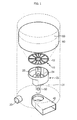
- Fig. 1 is a partially exploded perspective view of a conventional rotary type regenerative thermal oxidizer.
- a flow of process gases in the conventional regenerative thermal oxidizer is as follows.
- the process gases are drawn into a combustion chamber 60 after passing through an inlet pipe 30, an inlet opening 22 of a rotor 20, a plurality of openings 12 of a distribution plate 10, and a heat exchanging part 50, sequentially.
- the process gases are burned in the combustion chamber 60 and are discharged to the outside after passing through the openings 12 of the distribution plate 10, an outlet opening 24 of the rotor 20 and an outlet duct 40.
- An upper surface of the rotor 20 is in close contact with the distribution plate 10 having the plurality of openings 12.
- Some of the openings 12 formed on the distribution plate 10 correspond to the inlet opening 22 of the rotor 20 and the remainder of the openings 12 correspond to the outlet opening 24 of the rotor 20, thus providing inlet and outlet process gas flow paths, respectively.
- the openings 12 of the rotor 20 guide process gases passing through the inlet opening 22 to the heat exchanging part 50 and guide the process gases, which are burned after passing through the heat exchanging part 50, to the outlet opening 50 of the rotor 20.
- a partitioning unit (not shown) is provided between the heat exchanging part 50 and the distribution plate 10 to prevent the inlet process gases and the burned process gases from mixing with each other.
- a flow capacity of process gases is determined by areas of the inlet and outlet openings 22 and 24 of the rotor. Accordingly, to increase the flow of process gases, that is, the ability to process the process gases, the sectional area of the rotor must be increased. This purpose can be achieved by increasing the rotor size. However, to operate a large rotor, a drive unit having high power consumption is required. Due to this feature, manufacturing costs of the regenerative thermal oxidizer and costs of operating is are excessively increased.
- the increase in the size of the rotor causes difficulty in maintenance of an airtight state between the rotor and adjacent components.
- the rotor 20 shown in Fig. 1 must be airtightly coupled to adjacent components, such as an inlet chamber 31, the outlet duct 40 and the distribution plate 10.
- a sealing material is applied to predetermined portions of the rotor 20.
- the increase in the size of the rotor brings an increase in the area to which the sealing material must be applied. As a result, difficulty in providing a soundly airtight structure exists.
- the regenerative thermal oxidizer must prevent inlet and outlet process gases from mixing with each other in the rotor.
- the inlet process gas flow path and the outlet process gas flow path must be independently defined in a lower end of the rotor.
- the outlet duct 40 passing though the inlet chamber 31 is coupled to the rotor 20.
- the conventional regenerative thermal oxidizer is disadvantageous in that the structure is very complex.
- US5562442 shows a regenerative thermal oxidizer with a centrally positioned rotary distributor for controlling gas flow via a segmented center section.
- Incoming gas flows through a peripheral opening to a segmented upper section where it passes through a heat exchanger :o a combustion chamber where it is oxidized or cleansed. From there cleansed gas passes through another upper section segment through a heat exchanger and back to center section segment(s). In the center section the cleansed gas flows to the rotary distributor where it is divided into outgoing and purge gases. The outgoing gas flows through the rotor to a manifold and then to an outlet.
- US6203316 shows another regenerative oxidizer where a combustion chamber communicates with pie shaped heat exchange chambers.
- a rotary valve communicates with a second end of the heat exchange chambers.
- a contaminated gas is directed through an inlet of the rotary valve, through a first group of heat exchange chambers, and into the combustion chamber thereby heating and purifying the gas.
- the heated and purified gas is directed from the combustion chamber through a second group of heat exchange chambers and through an outlet of the rotary valve.
- an object of the present invention is to provide a regenerative thermal oxidizer which has a simple structure and increases process gas processing capacity in spite of having a rotor similar in size to typical rotors.
- the present invention provides a regenerative thermal oxidizer to burn process gases, comprising:
- the cylindrical rotor may include upper and lower cylinders which are integrally operated, so that the upper opening is provided on the upper surface of the upper cylinder and the lower opening is provided on the lower surface of the lower cylinder.
- the upper and lower cylinders comprise first and second side openings, respectively, so that both the upper opening and the first side opening are placed on the first gas flow path while both the lower opening and the second side opening are placed on the second gas flow path.
- the upper opening may be provided on a central portion of the upper surface of the cylindrical rotor, and the lower opening may be provided along a circumference of the lower surface of the cylindrical rotor.
- the cylindrical rotor may further include first and second side openings provided on opposite sidewalls of the cylindrical rotor, and both the upper opening and the first side opening are placed on the first gas flow path while both the second side opening and the lower opening are placed on the second gas flow path.
- the present invention provides a regenerative thermal oxidizer in which different parts of the rotor are used as inlet and outlet process gas flow paths, thus increasing process gas processing capacity in spite of having a rotor similar in size to typical rotors, and simplifying the structure of the rotor and adjacent components.
- a rotary type device for distribution of process gases is classified into a cylinder type distribution rotor and a plate type distribution rotor.
- the cylinder type distribution rotor means a rotor in which spaces for distribution of process gases are defined.
- the plate type distribution rotor means a rotor in which a planar distribution unit guides process gases in predetermined directions, but this rotor does not use an inner space thereof for the distribution of the process gases.
- Regenerative thermal oxidizer having cylinder type distribution rotor
- Figs. 2 through 4 are views of a regenerative thermal oxidizer having a cylinder type distribution rotor as a distribution unit, according to a first embodiment of the present invention.
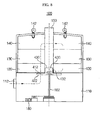
- Fig. 2 is a sectional view of the regenerative thermal oxidizer 100 of the present invention.
- the regenerative thermal oxidizer 100 according to the first embodiment includes a heat exchanging part 130.
- the heat exchanging part 130 partitions the interior of the regenerative thermal oxidizer 100 into upper and lower parts.
- the upper part of the regenerative thermal oxidizer 100 defines a combustion chamber 140 therein and the lower part of the regenerative thermal oxidizer 100 defines a distribution chamber 120 therein.
- the combustion chamber 140 has a combustion unit 142, such as a burner, to burn process gases.
- process gases drawn into the regenerative thermal oxidizer 100 through a second duct 112 pass through a cylinder type distribution rotor 200, the distribution chamber 120, the heat exchanging part 130 and the combustion chamber 140 and are burned in the combustion chamber 140.
- the burned process gases again pass through the heat exchanging part 130, the distribution chamber 120 and the rotor 200 and, thereafter, the burned process gases are exhausted to the outside through a first duct 150 passing through the heat exchanging part 130.
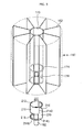
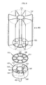
- Fig. 3 is a perspective view to show in detail the construction of the rotor used in the regenerative thermal oxidizer according to the first embodiment of the present invention.
- the rotor 200 is cylindrical.
- the interior of the rotor 200 is partitioned by an intermediate plate 216 into upper and lower parts.
- a first side opening 214A and a second side opening 214B are provided on sidewalls of the upper and lower parts of the rotor 200, respectively.
- an upper opening 212 and a lower opening 218 are provided on upper and lower surfaces of the rotor 200, respectively.
- the openings 212, 214A, 214B and 218 define inlet and outlet process gas flow paths.
- the first side opening 214A and the second side opening 214B are formed at diametrically opposite positions on the rotor 200 to be symmetrical to each other, based on a rotating shaft 182 of the rotor 200.
- the rotating shaft 182 is coupled to the intermediate plate 216 of the rotor 200.
- the rotor 200 is inserted into a separator 160 in the regenerative thermal oxidizer 100.
- the separator 160 supports a plurality of sectors of the heat exchanging part 130 therein and, in addition to, defines the distribution chamber 120 under the heat exchanging part 130.
- the separator 160 includes a cylindrical pipe 170 constituting the first duct 150.
- the separator 160 further includes a plurality of partitioning plates 162 which diametrically extend from the cylindrical pipe 170 outwards. The partitioning plates 162 support the heat exchanging part 130 and prevents inlet process gases and outlet process gases from mixing with each other in the distribution chamber 120.
- a plurality of slots 176 is provided on a sidewall 174 of a lower end of the cylindrical pipe 170 of the separator 160 to supply or discharge the process gases into or from the distribution chamber 120.
- the slots 176 corresponding to the first and second side openings 214A and 214B of the rotor 200 provide the inlet and outlet process gas flow paths.
- the process gases drawn into the regenerative thermal oxidizer 100 through the second duct 112 are supplied into the distribution chamber 120 through the lower opening 218 and the second side opening 214B of the rotor 200. Thereafter, the process gases are burned by the burner after passing through the heat exchanging part 130. The burned process gases again pass through the heat exchanging part 130 and the distribution chamber 120 prior to being drawn into the rotor 200 through the first side opening 214A of the rotor 200. Thereafter, the burned process gases are discharged to the outside through the upper opening 212 and the first duct 150.
- each of the slots 176 of the sidewall 174 of the lower end of the separator 160 may be divided into upper and lower parts to provide securely airtight flow of the process gases, but this is not shown in the drawings.
- the lower opening 218 for the inflow of the process gases and the upper opening 212 for the discharge of the burned process gases are formed on opposite surfaces of the rotor 200. Due to this structure, the flow of the process gases drawn into the rotor 200 and the flow of the burned process gases discharged from the rotor 200 are parallel with each other in the same direction. Unlike this feature, in conventional thermal oxidizers, process gases are drawn into and discharged from a cylinder through an opening formed on a lower surface of the cylinder, so that flows of inlet and outlet process gases are parallel to each other in opposite directions.
- the lower surface of the cylinder serves as both the inlet opening and the outlet opening.
- the regenerative thermal oxidizer of the present invention because the lower and upper surfaces of the rotor are used for the inflow and outflow of the process gases, respectively, a great amount of process gas can be processed.
- the second duct 112 for the inflow of the process gases and the first duct 150 for the outflow of the process gases are spatially separated from each other. Therefore, the pipe arrangement in the regenerative thermal oxidizer, as well as the construction of the rotor, is markedly simplified.
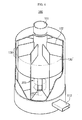
- Fig. 4 is a perspective view of the regenerative thermal oxidizer having the rotor of Fig. 2 .
- a plurality of sectors 130' of the heat exchanging part 130 is provided in the separator of the regenerative thermal oxidizer.
- the heat exchanging part 130 is made of predetermined material, in which a plurality of fine channels, that is, open pores, are formed, to exchange heat with the process gases while the process gases pass through the heat exchanging part 130.
- the heat exchanging part 130 includes the plurality of sectors 130' each having a pie shape and a predetermined internal angle. The sectors 130' are separated from each other by the partitioning plates 162 of the separator 160.
- the first duct 150 passes through the heat exchanging part 130 along a longitudinal axis of the heat exchanging part 130 to discharge burned process gases.
- the cylinder pipe 170 of the separator 160 which is described above with reference to Fig. 3 , constitutes the first duct 150.
- An end of the first duct 150 is in close contact with the upper opening (212 in Fig. 3 ) of the rotor.
- the other end of the first duct 150 extends to the outside of the regenerative thermal oxidizer after passing through the heat exchanging part 130.
- the partitioning plates 162 separate the sectors 130' of the heat exchanging part 130 and extend to a lower end of the rotor 200 to form the distribution chamber 120 in the regenerative thermal oxidizer 100.
- the partitioning plates 162 By the partitioning plates 162, the inlet and outlet process gases, which respectively flow along the inlet and outlet process gas flow paths defined by the second side opening 214B and the first side opening 214A of the rotor, are prevented from mixing with each other. Therefore, each of the sectors 130' of the heat exchanging part 130 is classified by the partitioning plates 162 into a process gas inflow side or a process gas outflow side.
- the rotor 200 is rotated by a motor 180 coupled to the rotating shaft 182.
- the rotor 200 is intermittently rotated as an angular unit corresponding to the internal angle of each of the sectors 130' of the heat exchanging part 130.
- each of the first side opening 214A and the second side opening 214B corresponds to other sectors 130' of the heat exchanging part 130.
- the sectors 130' which have been in the process gas outflow side, are moved into the process gas inflow side by the rotation of the rotor 200.
- new process gases, which flow in the process gas inflow side can be preheated by heat energy which is stored in the sectors 130', which have been in the process gas outflow side, by exchanging heat with the burned process gases in the process gas outflow side.
- each of the first and second side openings 214A and 214B of the rotor 200 has an elongate slot.
- each of the openings 214A and 214B may comprise a plurality of slots each having a predetermined circumferential length corresponding to an inside circumferential length of each of the sectors 130' of the heat exchanging part 130.
- the regenerative thermal oxidizer 100 may define therein a purge gas feed path for a supply of purge gas, as well as the inlet and outlet process gas flow paths, but the purge gas feed path is not shown in the drawings.
- an additional opening 214C may be formed on a predetermined portion of the rotor 200 to be aligned with a space between the first side opening 214A and the second side opening 214B.
- An axial center part of the rotating shaft 182 of the rotor 200 serves as a purge gas feed pipe and communicates with the opening 214C, thus defining the arrangement of the purge gas feed path.
- a design of the rotor adapted for the purge gas feed path is easily understood by a skilled person, therefore further explanation is deemed unnecessary.
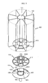
- Fig. 5 is a perspective view to show the construction of the cylinder type distribution rotor 300 used in the second embodiment.
- the rotor 300 shown in Fig. 5 has a lager diameter and a lower height than the rotor of the first embodiment shown in Fig. 3 .
- process gases are drawn from a lower end of the rotor and discharged through an upper end of the rotor in the same manner as that described for the rotor shown in Fig. 3 .
- the rotor 300 of the second embodiment has a cylindrical shape.
- the rotor 300 has a lower plate 320 and an upper plate 340 having a circular opening 312.
- a lower opening 318 has an arc shape and is formed along a circumference of the lower plate 320 of the rotor 300 to be elongated by a predetermined length.
- Two side openings 314A and 314B are provided on a sidewall of the rotor 300 for inflow and outflow of process gases.
- the upper opening 312, the lower opening 318 and the two side openings 314A and 314B form inlet and outlet process gas flow paths, guide the process gases into a combustion chamber, and allow the burned process gases to be discharged to the outside.
- a rotating shaft 182 is coupled to the lower plate 320 of the rotor 300.
- the lower opening 318 and the second side opening 314B of the rotor 300 guide process gases, drawn into the regenerative thermal oxidizer, to a distribution chamber (120 in Fig. 6 ).
- the first side opening 314A and the upper opening 312 guide the burned process gases from the distribution chamber 120 to a first duct (150 in Fig. 6 ).
- the process gases passing through both the lower opening 318 and the second side opening 314B are isolated by an inner wall 330 of the rotor 300 from the burned process gases passing through the first side opening 314A and the upper opening 312.
- the rotor 300 is inserted into the separator 160.
- the separator 160 supports a plurality of sectors of a heat exchanging part and defines therein the distribution chamber 120 below the heat exchanging part in the same manner as that described for the first embodiment.
- the separator 160 has an inner spatial part 170' which receive the rotor 300 therein. Furthermore, a plurality of openings 176' is formed on a sidewall of the inner spatial part 170' to correspond to the side openings 314A and 314B of the rotor.
- the rotor 300 may further include an additional opening 350 for the supply of purge air.
- the opening 350 is formed on a predetermined portion of the rotor 300 to be aligned with a space between the first and second side openings 314A and 314B.
- the opening 350 guides the purge air through the distribution chamber 120 to a part of the heat exchanging part 130 corresponding to the opening 350, thus purging the corresponding part of the heat exchanging part 130.
- the supplied purge air may serve as an air curtain for preventing inlet process gases and outlet process gases from mixing with each other.
- the purge air feed pipe is not shown in the drawings, but it may be designed in a typical method.
- an axially hollow center part of the rotating shaft 182 serves as the purge air feed pipe and communicates with the opening 350 through the interior of the rotor 300, thus defining the arrangement of the purge gas feed path.
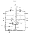
- Fig. 6 is a sectional view of the regenerative thermal oxidizer having the rotor of the second embodiment.
- process gases drawn through a second duct 112 pass through the lower opening 318 and second side opening 314B of the rotor 300, the distribution chamber 120 and the heat exchanging part 130 (see, the arrow of the one-dot chain line). Thereafter, the process gases are burned in a combustion chamber 140. The burned process gases again pass through the heat exchanging part 130 and the distribution chamber 120 prior to being discharged to the outside through the first side opening 314A and the upper opening 320 of the rotor 300.
- the heat exchanging part 130 includes sectors which have pie shapes and are separated from each other by partitioning plates 162 of the separator 160.
- the partitioning plates 162 extend to a lower end of the rotor 300 and form the distribution chamber 120 preventing inlet and outlet process gases from mixing with each other around the rotor 300.
- Regenerative thermal oxidizer having plate type distribution rotor
- Figs. 7 and 8 are views to show a regenerative thermal oxidizer having a plate type distribution rotor.
- Fig. 7 is a perspective view of the plate type distribution rotor.
- the rotor 400 includes an outer gas outlet 430B on a central portion thereof, and a distribution plate 410 which has a plurality of arc-shaped openings 412 along a circumference of the distribution plate 410.
- a plurality of outer slots 432 is provided on a sidewall of the outer gas outlet 430B. The size of each outer slot 432 may differ according to the width of each arc-shaped opening 412.
- the outer gas outlet 430B of the distribution plate 410 is fastened to a lower end of a separator 160 while being coupled to a first duct (150 in Fig. 8 ).
- the top of Fig. 7 illustrates the coupling of the distribution plate 410 to a lower end of a cylindrical pipe 170 of the separator 160.
- the rotor 400 is in close contact with the distribution plate 410 and includes a rotating plate 420 which is rotated by a rotating shaft 182.
- the rotating plate 420 has an inner gas outlet 430A on a central portion thereof.
- An inner slot 434 is formed at a predetermined position on the inner gas outlet 430A.
- the rotating plate 420 further has an arc-shaped rotating opening 422 which is formed on a predetermined portion along a circumference of the rotating plate 420.
- the distribution plate 410 and the rotating plate 420 constituting the rotor 400 are assembled together to function as a rotor type distribution unit.
- the inner gas outlet 430A of the rotating plate 420 is inserted into the outer gas outlet 430B of the distribution plate 410 to form together a single gas outlet set (430 in Fig. 8 ) which is integrally coupled to the first duct (150 in Fig. 8 ).
- the outer and inner slots 432 and 434 which are provided on the sidewalls of the outer and inner gas outlets 430B and 430A, respectively, guide process gases passing through a heat exchanging part (130 in Fig. 8 ) to the first duct 150, thus providing inlet and outlet process gas flow paths.
- the inner gas outlet 430A is rotatably inserted into the outer gas outlet 430B while a gap between them is sealed for airtight construction.
- a purge gas feed path for an inflow of purge gas into the rotor 400 may be defined.
- Fig. 7 illustrates a purge gas feed hole 424 which is provided at a predetermined position on the rotating plate.
- a separate purge gas feed pipe may be coupled to the purge gas feed hole 424 to feed the purge gas from the outside, but it is not shown in the drawings.
- the purge gas feed hole 424 may be formed at a predetermined position on a sidewall of the inner gas outlet 430A of the rotating plate 420. Such a structure is advantageous in that the hollow rotating shaft 182 is used for feeding purge gas.
- Fig. 8 is a sectional view of the regenerative thermal oxidizer.
- the construction of the rotor 400 is different from those of the first and second embodiments.
- constructions of a combustion chamber 140, the heat exchanging part 130, a distribution chamber 120 and an inlet chamber 110 are similar to those of the first and second embodiments, therefore further explanation is deemed unnecessary.
- a process gas flow path is as follows (see, the arrow of the one-dot chain line).
- Process gases drawn into the regenerative thermal oxidizer through a second duct 112
- the distribution chamber 120 along the inlet process gas flow path, which is defined by the openings 422 and 412 of the rotating plate 420 and the distribution plate 410 of the rotor, after passing through the inlet chamber 110.
- the drawn process gases pass through the heat exchanging part 130 and, thereafter, are burned in the combustion chamber 140. Thereafter, the burned process gases again pass through the heat exchanging part 130 prior to being guided to the first duct 150 through the inner and outer slots 434 and 432 of the gas outlet set 430 of the rotor 400.
- the distribution chamber 120 In the regenerative thermal oxidizer 100, the distribution chamber 120 must be airtightly assembled to the inlet chamber 110. To achieve the above-mentioned purpose, a predetermined sealing material is applied to an outer surface of the rotor 400.
- the distribution chamber 120 includes partitioning plates (162 in Fig. 7 ) which extend from the heat exchanging part 130 to the openings 412 and 422 of the rotor, thus preventing process gases drawn into the combustion chamber 140 and process gases discharged from the combustion chamber 140 from mixing with each other.
- the number of partitioning plates is determined by the number of sectors of the heat exchanging part 130.
- the outlet and inlet process gas flow paths are formed at upper and lower parts of the regenerative thermal oxidizer, based on the rotor. This simplifies the structure for separating the inlet and outlet process gases from each other in the rotor 400 or the inlet chamber 110.
- the rotor which is provided with a distribution ring having an inner space to separate inlet and outlet process gases from each other, the rotor can be regarded as a combination of the above-mentioned plate type distribution rotor and the cylinder type distribution rotor.
- Fig. 9 is a perspective view to show the construction of the plate type distribution rotor 500.
- the rotor 500 includes a distribution plate 510 and the distribution ring 520.
- a plurality of arc-shaped openings 512 is formed along the circumference of the distribution plate 510 around the center of the distribution plate 510 and spaced at regular angular intervals.
- the distribution plate 510 has a circular opening 530 on a central portion thereof.
- the circular opening 530 is coupled to a lower end of a cylindrical pipe 170 of a separator 160, thus being coupled to a first duct (150 in Fig. 10 ).
- the top of Fig. 9 illustrates the coupling of the distribution plate 510 to the lower end of the cylindrical pipe 170 of the separator 160.
- the distribution ring 520 includes an inner ring 540 and an outer ring 550 which support each other by at least two partitioning blades 545.
- the inner ring 540 is in close contact with the circular opening 530 of the distribution plate 510 to communicate with the first duct 150.
- a junction part between the inner ring 540 and the circular opening 530 is airtightly sealed by a predetermined sealing material while the inner ring 540 and the circular opening 530 are rotatably assembled with each other.
- the inner ring 540 has a side opening 542.
- a rotating shaft is coupled to a lower end of the inner ring 540.
- a space between the inner ring and the outer ring is partitioned by the partitioning blades 545 into three regions.
- a first region (A) having an opening 545 relates to an inflow of process gases.
- the first region (A) which is called the inlet region (A) guides the process gases, drawn into the rotor 500, to a distribution chamber (120 in Fig. 10 ).
- a second region (B) communicates with the side opening 542 of the inner ring 540 and relates to an outflow of the process gases.
- the second region (B) which is called the outlet region (B), guides the burned process gases into the first duct.
- a third region (C) is defined between the inlet region (A) and the outlet region (B) and relates to a supply of purge gas for purging part of a heat exchanging part corresponding to the third region (C).
- the supplied purge air may serve as an air curtain for preventing inlet process gases and outlet process gases from mixing with each other.
- a purge gas feed pipe associated with the supply of the purge gas through the purge gas feed region (C) is not shown in the drawings, but it is typically designed. For example, the purge gas passes through a hollow center axle of the rotating shaft 182 and, thereafter, is drawn into the purge gas feed region (C) through a predetermined pipe passing through the inner ring 540.
- Fig. 10 is a sectional view of the regenerative thermal oxidizer 100 provided with the above-mentioned rotor 500.
- the construction of the rotor 500 is different from those previously described.
- the construction of a combustion chamber 140, the heat exchanging part 130, a distribution chamber 120 and an inlet chamber 110 are similar, therefore further explanation is deemed unnecessary.
- a process gas flow path is as follows (see, the arrow of the one-dot chain line).
- Process gases drawn into the regenerative thermal oxidizer through a second duct 112 are supplied into the distribution chamber 120 through the inlet chamber 110 and the inlet region (A) of the outer ring 550 of the rotor 500.
- the drawn process gases pass through the heat exchanging part 130 and, thereafter, are burned in the combustion chamber 140. Thereafter, the burned process gases again pass through the heat exchanging part 130 prior to being guided to the first duct 150 through the outlet region (B) of the outer ring 550, the side opening 542 of the inner ring 540 and the circular opening 530 of the distribution plate 510 of the rotor 500.
- the distribution chamber 120 includes partitioning plates (162 in Fig. 9 ) which extend to an upper end of the rotor 500, thus preventing process gases drawn into the combustion chamber 140 and process gases discharged from the combustion chamber 140 from mixing with each other.
- the partitioning plates 162 partition the heat exchanging part 130 into several sectors.
- the regenerative thermal oxidizer provided with the rotor having the above-mentioned construction uses upper and lower surfaces of the rotor as outlet and inlet process gas flow paths. Therefore, the regenerative thermal oxidizer is advantageous in that the amount of process gases to be treated at one time is increased and, in addition, the construction of the rotor and the inlet chamber 110 is simplified.
- the inlet and outlet process gas flow paths may be switched.
- the first duct coupled to the upper end of the rotor may serve as an inlet pipe for the inflow of process gases and the second duct placed below the rotor may serve as an outer duct.
- the regenerative thermal oxidizer having the heat exchanging part may further include a catalyst layer on the heat exchanging part.
- the present invention provides a regenerative thermal oxidizer which has a distribution unit to distribute process gases above and below the distribution unit, so that the construction of the distribution unit is simplified and, as well, the present invention can treat a greater amount of process gases than conventional oxidizers in spite of having a distribution unit similar in size to conventional distribution units. Therefore, the present invention reduces the production costs of the regenerative thermal oxidizer and the costs of operating it.
Landscapes
- Engineering & Computer Science (AREA)
- Mechanical Engineering (AREA)
- General Engineering & Computer Science (AREA)
- Environmental & Geological Engineering (AREA)
- Physics & Mathematics (AREA)
- Thermal Sciences (AREA)
- Incineration Of Waste (AREA)
- Heat-Exchange Devices With Radiators And Conduit Assemblies (AREA)
Description
- The present invention relates, in general, to thermal oxidizers to burn and eliminate harmful process gases generated at industrial sites and, more particularly, to a regenerative thermal oxidizer which has a heat exchanging part placed in a gas flow path.
- Generally, there are various kinds of thermal oxidizers to oxidize harmful gases, such as volatile organic compounds, resulting from process gases in industrial site and to discharge the oxidized products to the outside. Regenerative thermal oxidizers, which are capable of preheating inlet process gases using the high heat energy of outlet process gases resulting from combustion of the process gases, have advantages of saving energy and of efficiently eliminating harmful gases.
- Conventional regenerative thermal oxidizers each include a combustion chamber which bums and oxidizes process gases, a heat exchanging part and a rotor which periodically rotates to supply or discharge the process gases into or from the combustion chamber. Process gases supplied from the rotor are burned in the combustion chamber after passing through the heat exchanging part. Thereafter, the burned process gases are discharged to the outside through the heat exchanging part and the rotor. In this process, a section of the heat exchanging part functioning to discharge gas stores heat energy from combustion gases. The heat energy is used to preheat process gases supplied from the rotor.
-
Fig. 1 is a partially exploded perspective view of a conventional rotary type regenerative thermal oxidizer. - With reference to
Fig. 1 , a flow of process gases in the conventional regenerative thermal oxidizer is as follows. The process gases are drawn into acombustion chamber 60 after passing through aninlet pipe 30, an inlet opening 22 of arotor 20, a plurality ofopenings 12 of adistribution plate 10, and aheat exchanging part 50, sequentially. The process gases are burned in thecombustion chamber 60 and are discharged to the outside after passing through theopenings 12 of thedistribution plate 10, an outlet opening 24 of therotor 20 and an outlet duct 40. - An upper surface of the
rotor 20 is in close contact with thedistribution plate 10 having the plurality ofopenings 12. Some of theopenings 12 formed on thedistribution plate 10 correspond to the inlet opening 22 of therotor 20 and the remainder of theopenings 12 correspond to the outlet opening 24 of therotor 20, thus providing inlet and outlet process gas flow paths, respectively. In other words, theopenings 12 of therotor 20 guide process gases passing through the inlet opening 22 to theheat exchanging part 50 and guide the process gases, which are burned after passing through theheat exchanging part 50, to the outlet opening 50 of therotor 20. A partitioning unit (not shown) is provided between theheat exchanging part 50 and thedistribution plate 10 to prevent the inlet process gases and the burned process gases from mixing with each other. - In the conventional regenerative thermal oxidizer, because the
rotor 20 separates inlet and outlet process gases from each other, a flow capacity of process gases is determined by areas of the inlet andoutlet openings - The increase in the size of the rotor causes difficulty in maintenance of an airtight state between the rotor and adjacent components. For example, the
rotor 20 shown inFig. 1 must be airtightly coupled to adjacent components, such as aninlet chamber 31, the outlet duct 40 and thedistribution plate 10. To achieve the above-mentioned purpose, a sealing material is applied to predetermined portions of therotor 20. The increase in the size of the rotor brings an increase in the area to which the sealing material must be applied. As a result, difficulty in providing a soundly airtight structure exists. - In the meantime, the regenerative thermal oxidizer must prevent inlet and outlet process gases from mixing with each other in the rotor. As well, the inlet process gas flow path and the outlet process gas flow path must be independently defined in a lower end of the rotor. Furthermore, in the regenerative thermal oxidizer shown in
Fig. 1 , the outlet duct 40 passing though theinlet chamber 31 is coupled to therotor 20. As such, the conventional regenerative thermal oxidizer is disadvantageous in that the structure is very complex. -
US5562442 shows a regenerative thermal oxidizer with a centrally positioned rotary distributor for controlling gas flow via a segmented center section. Incoming gas flows through a peripheral opening to a segmented upper section where it passes through a heat exchanger :o a combustion chamber where it is oxidized or cleansed. From there cleansed gas passes through another upper section segment through a heat exchanger and back to center section segment(s). In the center section the cleansed gas flows to the rotary distributor where it is divided into outgoing and purge gases. The outgoing gas flows through the rotor to a manifold and then to an outlet. -
US6203316 shows another regenerative oxidizer where a combustion chamber communicates with pie shaped heat exchange chambers. A rotary valve communicates with a second end of the heat exchange chambers. A contaminated gas is directed through an inlet of the rotary valve, through a first group of heat exchange chambers, and into the combustion chamber thereby heating and purifying the gas. The heated and purified gas is directed from the combustion chamber through a second group of heat exchange chambers and through an outlet of the rotary valve. - Accordingly, the present invention has been made keeping in mind the above problems occurring in the prior art, and an object of the present invention is to provide a regenerative thermal oxidizer which has a simple structure and increases process gas processing capacity in spite of having a rotor similar in size to typical rotors.
- In order to accomplish the above object, the present invention provides a regenerative thermal oxidizer to burn process gases, comprising:
- a reaction chamber having a combustion unit to burn the process gases;
- a heat exchanging part placed to be in contact with the reaction chamber and comprising a plurality of sectors for heat exchange of the process gases;
- a first duct;
- a second duct provided on a lower end of the regenerative thermal oxidizer to supply or discharge the process gases into or from the heat exchanging part;
- a cylindrical rotor provided under the heat exchanging part, and comprising: an upper opening provided on an upper surface of the cylindrical rotor; and a lower opening provided on a lower surface of the cylindrical rotor opposite to the upper opening, wherein the upper opening provides a first gas flow path to connect some of the sectors of the heat exchanging part to the outside of the regenerative thermal oxidizer through the first duct, and the lower opening provides a second gas flow path to connect other sectors of the heat exchanging part to the outside of the regenerative thermal oxidizer through the second duct;
- a plurality of partitioning plates to define the sectors of the heat exchanging part and to prevent the process gases passing through the first and second gas flow paths below the heat exchanging part from mixing with each other; and
- a drive unit coupled to a lower end of the cylindrical rotor to rotate the cylindrical rotor at a predetermined speed,
- wherein
- the first duct communicates with the outside through an upper end of the regenerative thermal oxidizer while passing through the heat exchanging part and in that the upper surface of the cylindrical rotor is in contact with the first duct. According to an embodiment of the present invention, the rotor-shaped distribution unit of the regenerative thermal oxidizer may comprise a cylindrical rotor provided under the heat exchanging part, and including: an upper opening provided on an upper surface of the cylindrical rotor which is in contact with the first duct; and a lower opening provided on a lower surface of the cylindrical rotor opposite to the upper opening, so that the upper opening provides a first gas flow path to connect a part of the sectors of the heat exchanging part to the outside of the regenerative thermal oxidizer through the first duct, and the lower opening provides a second gas flow path to connect another part of the sectors of the heat exchanging part to the outside of the regenerative thermal oxidizer through the second duct.
- The cylindrical rotor may include upper and lower cylinders which are integrally operated, so that the upper opening is provided on the upper surface of the upper cylinder and the lower opening is provided on the lower surface of the lower cylinder. The upper and lower cylinders comprise first and second side openings, respectively, so that both the upper opening and the first side opening are placed on the first gas flow path while both the lower opening and the second side opening are placed on the second gas flow path. The upper opening may be provided on a central portion of the upper surface of the cylindrical rotor, and the lower opening may be provided along a circumference of the lower surface of the cylindrical rotor. The cylindrical rotor may further include first and second side openings provided on opposite sidewalls of the cylindrical rotor, and both the upper opening and the first side opening are placed on the first gas flow path while both the second side opening and the lower opening are placed on the second gas flow path.
- As described above, the present invention provides a regenerative thermal oxidizer in which different parts of the rotor are used as inlet and outlet process gas flow paths, thus increasing process gas processing capacity in spite of having a rotor similar in size to typical rotors, and simplifying the structure of the rotor and adjacent components.
- The above and other objects, features and other advantages of the present invention will be more clearly understood from the following detailed description taken in conjunction with the accompanying drawings, in which:
-
Fig. 1 is a partially exploded perspective view of a conventional rotary type regenerative thermal oxidizer centered on a rotor; -
Fig. 2 is a sectional view of a regenerative thermal oxidizer having a cylinder type distribution rotor as a distribution unit, according to an embodiment of the present invention; -
Fig. 3 is a perspective view to show in detail the construction of the rotor used in the regenerative thermal oxidizer ofFig. 2 ; -
Fig. 4 is a perspective view of the regenerative thermal oxidizer having the rotor ofFig. 3 ; -
Fig. 5 is a perspective view to show a distribution unit having a cylindrical distribution rotor type, according to another embodiment of the present invention; -
Fig. 6 is a sectional view of a regenerative thermal oxidizer having the rotor ofFig. 5 ; -
Fig. 7 is a perspective view to show a plate type distribution rotor; -
Fig. 8 is a sectional view of a regenerative thermal oxidizer having the rotor ofFig. 7 ; -
Fig. 9 is a perspective view to show a plate type distribution rotor; and -
Fig. 10 is a sectional view of a regenerative thermal oxidizer having the rotor ofFig. 9 . - Hereinafter, embodiments of the present invention will be described in detail with reference to the accompanying drawings.
- In the following description, for the sake of convenience, a rotary type device for distribution of process gases is classified into a cylinder type distribution rotor and a plate type distribution rotor. The cylinder type distribution rotor means a rotor in which spaces for distribution of process gases are defined. The plate type distribution rotor means a rotor in which a planar distribution unit guides process gases in predetermined directions, but this rotor does not use an inner space thereof for the distribution of the process gases. Reference should now be made to the drawings, in which the same reference numerals are used throughout the different drawings to designate the same or similar components.
-
Figs. 2 through 4 are views of a regenerative thermal oxidizer having a cylinder type distribution rotor as a distribution unit, according to a first embodiment of the present invention. -
Fig. 2 is a sectional view of the regenerativethermal oxidizer 100 of the present invention. As shown in the drawings, the regenerativethermal oxidizer 100 according to the first embodiment includes aheat exchanging part 130. Theheat exchanging part 130 partitions the interior of the regenerativethermal oxidizer 100 into upper and lower parts. The upper part of the regenerativethermal oxidizer 100 defines acombustion chamber 140 therein and the lower part of the regenerativethermal oxidizer 100 defines adistribution chamber 120 therein. Thecombustion chamber 140 has acombustion unit 142, such as a burner, to burn process gases. - As shown by the arrow, process gases, drawn into the regenerative
thermal oxidizer 100 through asecond duct 112, pass through a cylindertype distribution rotor 200, thedistribution chamber 120, theheat exchanging part 130 and thecombustion chamber 140 and are burned in thecombustion chamber 140. The burned process gases again pass through theheat exchanging part 130, thedistribution chamber 120 and therotor 200 and, thereafter, the burned process gases are exhausted to the outside through afirst duct 150 passing through theheat exchanging part 130. -
Fig. 3 is a perspective view to show in detail the construction of the rotor used in the regenerative thermal oxidizer according to the first embodiment of the present invention. Therotor 200 is cylindrical. The interior of therotor 200 is partitioned by anintermediate plate 216 into upper and lower parts. Afirst side opening 214A and a second side opening 214B are provided on sidewalls of the upper and lower parts of therotor 200, respectively. Furthermore, anupper opening 212 and alower opening 218 are provided on upper and lower surfaces of therotor 200, respectively. Theopenings rotor 200, thefirst side opening 214A and the second side opening 214B are formed at diametrically opposite positions on therotor 200 to be symmetrical to each other, based on arotating shaft 182 of therotor 200. Therotating shaft 182 is coupled to theintermediate plate 216 of therotor 200. - Referring to
Fig. 3 , therotor 200 is inserted into aseparator 160 in the regenerativethermal oxidizer 100. Theseparator 160 supports a plurality of sectors of theheat exchanging part 130 therein and, in addition to, defines thedistribution chamber 120 under theheat exchanging part 130. As shown in the drawings, theseparator 160 includes acylindrical pipe 170 constituting thefirst duct 150. Theseparator 160 further includes a plurality ofpartitioning plates 162 which diametrically extend from thecylindrical pipe 170 outwards. Thepartitioning plates 162 support theheat exchanging part 130 and prevents inlet process gases and outlet process gases from mixing with each other in thedistribution chamber 120. A plurality ofslots 176 is provided on asidewall 174 of a lower end of thecylindrical pipe 170 of theseparator 160 to supply or discharge the process gases into or from thedistribution chamber 120. Theslots 176 corresponding to the first andsecond side openings rotor 200 provide the inlet and outlet process gas flow paths. - The inlet and outlet process gas flow paths will be described herein below, with reference to
Figs. 2 and3 . As shown by the arrow of the one-dot chain line, the process gases, drawn into the regenerativethermal oxidizer 100 through thesecond duct 112, are supplied into thedistribution chamber 120 through thelower opening 218 and the second side opening 214B of therotor 200. Thereafter, the process gases are burned by the burner after passing through theheat exchanging part 130. The burned process gases again pass through theheat exchanging part 130 and thedistribution chamber 120 prior to being drawn into therotor 200 through the first side opening 214A of therotor 200. Thereafter, the burned process gases are discharged to the outside through theupper opening 212 and thefirst duct 150. As described above, in the flow of the process gases from thedistribution chamber 120 to thefirst side opening 214A and in the flow of the process gases from the second side opening 214B to thedistribution chamber 120, the process gases always pass through the plurality ofslots 176 formed on thesidewall 174 of the lower end of theseparator 160. Here, each of theslots 176 of thesidewall 174 of the lower end of theseparator 160 may be divided into upper and lower parts to provide securely airtight flow of the process gases, but this is not shown in the drawings. - In the regenerative
thermal oxidizer 100 of the present invention, thelower opening 218 for the inflow of the process gases and theupper opening 212 for the discharge of the burned process gases are formed on opposite surfaces of therotor 200. Due to this structure, the flow of the process gases drawn into therotor 200 and the flow of the burned process gases discharged from therotor 200 are parallel with each other in the same direction. Unlike this feature, in conventional thermal oxidizers, process gases are drawn into and discharged from a cylinder through an opening formed on a lower surface of the cylinder, so that flows of inlet and outlet process gases are parallel to each other in opposite directions. - As such, in conventional thermal oxidizers, the lower surface of the cylinder serves as both the inlet opening and the outlet opening. However, in the regenerative thermal oxidizer of the present invention, because the lower and upper surfaces of the rotor are used for the inflow and outflow of the process gases, respectively, a great amount of process gas can be processed. Furthermore, in the regenerative thermal oxidizer of the present invention, the
second duct 112 for the inflow of the process gases and thefirst duct 150 for the outflow of the process gases are spatially separated from each other. Therefore, the pipe arrangement in the regenerative thermal oxidizer, as well as the construction of the rotor, is markedly simplified. -
Fig. 4 is a perspective view of the regenerative thermal oxidizer having the rotor ofFig. 2 . As shown inFig. 4 , a plurality of sectors 130' of theheat exchanging part 130 is provided in the separator of the regenerative thermal oxidizer. Theheat exchanging part 130 is made of predetermined material, in which a plurality of fine channels, that is, open pores, are formed, to exchange heat with the process gases while the process gases pass through theheat exchanging part 130. As shown in the drawings, theheat exchanging part 130 includes the plurality of sectors 130' each having a pie shape and a predetermined internal angle. The sectors 130' are separated from each other by thepartitioning plates 162 of theseparator 160. Thefirst duct 150 passes through theheat exchanging part 130 along a longitudinal axis of theheat exchanging part 130 to discharge burned process gases. Thecylinder pipe 170 of theseparator 160, which is described above with reference toFig. 3 , constitutes thefirst duct 150. An end of thefirst duct 150 is in close contact with the upper opening (212 inFig. 3 ) of the rotor. The other end of thefirst duct 150 extends to the outside of the regenerative thermal oxidizer after passing through theheat exchanging part 130. - The
partitioning plates 162 separate the sectors 130' of theheat exchanging part 130 and extend to a lower end of therotor 200 to form thedistribution chamber 120 in the regenerativethermal oxidizer 100. By thepartitioning plates 162, the inlet and outlet process gases, which respectively flow along the inlet and outlet process gas flow paths defined by the second side opening 214B and the first side opening 214A of the rotor, are prevented from mixing with each other. Therefore, each of the sectors 130' of theheat exchanging part 130 is classified by thepartitioning plates 162 into a process gas inflow side or a process gas outflow side. - The
rotor 200 is rotated by amotor 180 coupled to therotating shaft 182. For example, therotor 200 is intermittently rotated as an angular unit corresponding to the internal angle of each of the sectors 130' of theheat exchanging part 130. According to the rotation of therotor 200, each of thefirst side opening 214A and thesecond side opening 214B corresponds to other sectors 130' of theheat exchanging part 130. In other words, the sectors 130', which have been in the process gas outflow side, are moved into the process gas inflow side by the rotation of therotor 200. Thus, new process gases, which flow in the process gas inflow side, can be preheated by heat energy which is stored in the sectors 130', which have been in the process gas outflow side, by exchanging heat with the burned process gases in the process gas outflow side. - As shown in
FIG. 3 , each of the first andsecond side openings rotor 200 has an elongate slot. However, alternatively, each of theopenings heat exchanging part 130. - Furthermore, the regenerative
thermal oxidizer 100 according to the first embodiment may define therein a purge gas feed path for a supply of purge gas, as well as the inlet and outlet process gas flow paths, but the purge gas feed path is not shown in the drawings. To achieve the above-mentioned purpose, an additional opening 214C may be formed on a predetermined portion of therotor 200 to be aligned with a space between thefirst side opening 214A and the second side opening 214B. An axial center part of therotating shaft 182 of therotor 200 serves as a purge gas feed pipe and communicates with the opening 214C, thus defining the arrangement of the purge gas feed path. A design of the rotor adapted for the purge gas feed path is easily understood by a skilled person, therefore further explanation is deemed unnecessary. - Hereinafter, a regenerative thermal oxidizer having a cylinder type distribution rotor as a distribution unit according to a second embodiment of the present invention will be described, with reference to
Figs. 5 and6 . -
Fig. 5 is a perspective view to show the construction of the cylindertype distribution rotor 300 used in the second embodiment. Therotor 300 shown inFig. 5 has a lager diameter and a lower height than the rotor of the first embodiment shown inFig. 3 . However, process gases are drawn from a lower end of the rotor and discharged through an upper end of the rotor in the same manner as that described for the rotor shown inFig. 3 . - Referring to
Fig. 5 , therotor 300 of the second embodiment has a cylindrical shape. Therotor 300 has alower plate 320 and anupper plate 340 having acircular opening 312. Alower opening 318 has an arc shape and is formed along a circumference of thelower plate 320 of therotor 300 to be elongated by a predetermined length. Twoside openings rotor 300 for inflow and outflow of process gases. Theupper opening 312, thelower opening 318 and the twoside openings rotating shaft 182 is coupled to thelower plate 320 of therotor 300. - The
lower opening 318 and the second side opening 314B of therotor 300 guide process gases, drawn into the regenerative thermal oxidizer, to a distribution chamber (120 inFig. 6 ). Thefirst side opening 314A and theupper opening 312 guide the burned process gases from thedistribution chamber 120 to a first duct (150 inFig. 6 ). The process gases passing through both thelower opening 318 and the second side opening 314B are isolated by aninner wall 330 of therotor 300 from the burned process gases passing through thefirst side opening 314A and theupper opening 312. When therotor 300 is coupled to aseparator 160, theupper surface 340 of therotor 300 is rotatably in close contact with thefirst duct 150. - The
rotor 300 is inserted into theseparator 160. Theseparator 160 supports a plurality of sectors of a heat exchanging part and defines therein thedistribution chamber 120 below the heat exchanging part in the same manner as that described for the first embodiment. Theseparator 160 has an inner spatial part 170' which receive therotor 300 therein. Furthermore, a plurality of openings 176' is formed on a sidewall of the inner spatial part 170' to correspond to theside openings - In the meantime, as shown in the drawings, the
rotor 300 may further include anadditional opening 350 for the supply of purge air. Theopening 350 is formed on a predetermined portion of therotor 300 to be aligned with a space between the first andsecond side openings opening 350 guides the purge air through thedistribution chamber 120 to a part of theheat exchanging part 130 corresponding to theopening 350, thus purging the corresponding part of theheat exchanging part 130. When purge air is drawn at a pressure higher than process gases, the supplied purge air may serve as an air curtain for preventing inlet process gases and outlet process gases from mixing with each other. The purge air feed pipe is not shown in the drawings, but it may be designed in a typical method. For example, an axially hollow center part of therotating shaft 182 serves as the purge air feed pipe and communicates with theopening 350 through the interior of therotor 300, thus defining the arrangement of the purge gas feed path. -
Fig. 6 is a sectional view of the regenerative thermal oxidizer having the rotor of the second embodiment. Referring toFig. 6 , process gases drawn through asecond duct 112 pass through thelower opening 318 and second side opening 314B of therotor 300, thedistribution chamber 120 and the heat exchanging part 130 (see, the arrow of the one-dot chain line). Thereafter, the process gases are burned in acombustion chamber 140. The burned process gases again pass through theheat exchanging part 130 and thedistribution chamber 120 prior to being discharged to the outside through thefirst side opening 314A and theupper opening 320 of therotor 300. - In the same manner as that of the first embodiment, the
heat exchanging part 130 includes sectors which have pie shapes and are separated from each other by partitioningplates 162 of theseparator 160. Thepartitioning plates 162 extend to a lower end of therotor 300 and form thedistribution chamber 120 preventing inlet and outlet process gases from mixing with each other around therotor 300. - The principle of the heat exchange occurring between the
heat exchanging part 130 and the process gases during the rotation of therotor 300 is the same as that of the first embodiment, therefore further explanation of the principle is deemed unnecessary. - Until now, although the regenerative thermal oxidizer having the cylinder type distribution rotor has been described. Hereinafter, a regenerative thermal oxidizer having a plate type distribution rotor functioning as a distribution unit is described with reference to
Figs. 7 through 10 . -
Figs. 7 and8 are views to show a regenerative thermal oxidizer having a plate type distribution rotor. -
Fig. 7 is a perspective view of the plate type distribution rotor. - Referring to
Fig. 7 , therotor 400 includes anouter gas outlet 430B on a central portion thereof, and adistribution plate 410 which has a plurality of arc-shapedopenings 412 along a circumference of thedistribution plate 410. A plurality ofouter slots 432 is provided on a sidewall of theouter gas outlet 430B. The size of eachouter slot 432 may differ according to the width of each arc-shapedopening 412. Theouter gas outlet 430B of thedistribution plate 410 is fastened to a lower end of aseparator 160 while being coupled to a first duct (150 inFig. 8 ). The top ofFig. 7 illustrates the coupling of thedistribution plate 410 to a lower end of acylindrical pipe 170 of theseparator 160. - Furthermore, the
rotor 400 is in close contact with thedistribution plate 410 and includes arotating plate 420 which is rotated by arotating shaft 182. Therotating plate 420 has aninner gas outlet 430A on a central portion thereof. Aninner slot 434 is formed at a predetermined position on theinner gas outlet 430A. Therotating plate 420 further has an arc-shapedrotating opening 422 which is formed on a predetermined portion along a circumference of therotating plate 420. - The
distribution plate 410 and therotating plate 420 constituting therotor 400 are assembled together to function as a rotor type distribution unit. Theinner gas outlet 430A of therotating plate 420 is inserted into theouter gas outlet 430B of thedistribution plate 410 to form together a single gas outlet set (430 inFig. 8 ) which is integrally coupled to the first duct (150 inFig. 8 ). The outer andinner slots inner gas outlets Fig. 8 ) to thefirst duct 150, thus providing inlet and outlet process gas flow paths. Theinner gas outlet 430A is rotatably inserted into theouter gas outlet 430B while a gap between them is sealed for airtight construction. - In the state of being assembled together, some of the arc-shaped
openings 412 of thedistribution plate 410 corresponding to therotating opening 422 of therotating plate 420 are associated with the inflow of the process gases into theheat exchanging part 130. The remaining arc-shapedopenings 412, which do not correspond to therotating opening 422 of therotating plate 420, are not concerned with the inflow of the process gases. In the third embodiment, a purge gas feed path for an inflow of purge gas into therotor 400 may be defined.Fig. 7 illustrates a purgegas feed hole 424 which is provided at a predetermined position on the rotating plate. A separate purge gas feed pipe may be coupled to the purgegas feed hole 424 to feed the purge gas from the outside, but it is not shown in the drawings. Unlike what is shown in the drawings, the purgegas feed hole 424 may be formed at a predetermined position on a sidewall of theinner gas outlet 430A of therotating plate 420. Such a structure is advantageous in that the hollowrotating shaft 182 is used for feeding purge gas. -
Fig. 8 is a sectional view of the regenerative thermal oxidizer. - In the regenerative
thermal oxidizer 100, the construction of therotor 400 is different from those of the first and second embodiments. However, constructions of acombustion chamber 140, theheat exchanging part 130, adistribution chamber 120 and aninlet chamber 110 are similar to those of the first and second embodiments, therefore further explanation is deemed unnecessary. - With reference to
Fig. 8 , a process gas flow path is as follows (see, the arrow of the one-dot chain line). Process gases, drawn into the regenerative thermal oxidizer through asecond duct 112, are supplied into thedistribution chamber 120 along the inlet process gas flow path, which is defined by theopenings rotating plate 420 and thedistribution plate 410 of the rotor, after passing through theinlet chamber 110. The drawn process gases pass through theheat exchanging part 130 and, thereafter, are burned in thecombustion chamber 140. Thereafter, the burned process gases again pass through theheat exchanging part 130 prior to being guided to thefirst duct 150 through the inner andouter slots rotor 400. - In the regenerative
thermal oxidizer 100, thedistribution chamber 120 must be airtightly assembled to theinlet chamber 110. To achieve the above-mentioned purpose, a predetermined sealing material is applied to an outer surface of therotor 400. Thedistribution chamber 120 includes partitioning plates (162 inFig. 7 ) which extend from theheat exchanging part 130 to theopenings combustion chamber 140 and process gases discharged from thecombustion chamber 140 from mixing with each other. The number of partitioning plates is determined by the number of sectors of theheat exchanging part 130. - In the same manner as the first and second embodiments, the outlet and inlet process gas flow paths are formed at upper and lower parts of the regenerative thermal oxidizer, based on the rotor. This simplifies the structure for separating the inlet and outlet process gases from each other in the
rotor 400 or theinlet chamber 110. - Hereinafter, a regenerative thermal oxidizer having a plate type distribution rotor will be described with reference to
Figs. 9 and10 . In regards to the rotor which is provided with a distribution ring having an inner space to separate inlet and outlet process gases from each other, the rotor can be regarded as a combination of the above-mentioned plate type distribution rotor and the cylinder type distribution rotor. -
Fig. 9 is a perspective view to show the construction of the platetype distribution rotor 500. - Referring to
Fig. 9 , therotor 500 includes adistribution plate 510 and thedistribution ring 520. A plurality of arc-shapedopenings 512 is formed along the circumference of thedistribution plate 510 around the center of thedistribution plate 510 and spaced at regular angular intervals. Thedistribution plate 510 has acircular opening 530 on a central portion thereof. Thecircular opening 530 is coupled to a lower end of acylindrical pipe 170 of aseparator 160, thus being coupled to a first duct (150 inFig. 10 ). The top ofFig. 9 illustrates the coupling of thedistribution plate 510 to the lower end of thecylindrical pipe 170 of theseparator 160. - The
distribution ring 520 includes aninner ring 540 and anouter ring 550 which support each other by at least two partitioningblades 545. Theinner ring 540 is in close contact with thecircular opening 530 of thedistribution plate 510 to communicate with thefirst duct 150. A junction part between theinner ring 540 and thecircular opening 530 is airtightly sealed by a predetermined sealing material while theinner ring 540 and thecircular opening 530 are rotatably assembled with each other. Furthermore, theinner ring 540 has aside opening 542. A rotating shaft is coupled to a lower end of theinner ring 540. - As shown in the drawings, a space between the inner ring and the outer ring is partitioned by the
partitioning blades 545 into three regions. A first region (A) having anopening 545 relates to an inflow of process gases. The first region (A), which is called the inlet region (A), guides the process gases, drawn into therotor 500, to a distribution chamber (120 inFig. 10 ). A second region (B) communicates with theside opening 542 of theinner ring 540 and relates to an outflow of the process gases. The second region (B), which is called the outlet region (B), guides the burned process gases into the first duct. A third region (C) is defined between the inlet region (A) and the outlet region (B) and relates to a supply of purge gas for purging part of a heat exchanging part corresponding to the third region (C). When purge gas is drawn at a pressure higher than process gases, the supplied purge air may serve as an air curtain for preventing inlet process gases and outlet process gases from mixing with each other. A purge gas feed pipe associated with the supply of the purge gas through the purge gas feed region (C) is not shown in the drawings, but it is typically designed. For example, the purge gas passes through a hollow center axle of therotating shaft 182 and, thereafter, is drawn into the purge gas feed region (C) through a predetermined pipe passing through theinner ring 540. -
Fig. 10 is a sectional view of the regenerativethermal oxidizer 100 provided with the above-mentionedrotor 500. - In this regenerative
thermal oxidizer 100, the construction of therotor 500 is different from those previously described. However, the construction of acombustion chamber 140, theheat exchanging part 130, adistribution chamber 120 and aninlet chamber 110 are similar, therefore further explanation is deemed unnecessary. - With reference to
Fig. 10 , a process gas flow path is as follows (see, the arrow of the one-dot chain line). Process gases, drawn into the regenerative thermal oxidizer through asecond duct 112, are supplied into thedistribution chamber 120 through theinlet chamber 110 and the inlet region (A) of theouter ring 550 of therotor 500. The drawn process gases pass through theheat exchanging part 130 and, thereafter, are burned in thecombustion chamber 140. Thereafter, the burned process gases again pass through theheat exchanging part 130 prior to being guided to thefirst duct 150 through the outlet region (B) of theouter ring 550, theside opening 542 of theinner ring 540 and thecircular opening 530 of thedistribution plate 510 of therotor 500. - The
distribution chamber 120 includes partitioning plates (162 inFig. 9 ) which extend to an upper end of therotor 500, thus preventing process gases drawn into thecombustion chamber 140 and process gases discharged from thecombustion chamber 140 from mixing with each other. Thepartitioning plates 162 partition theheat exchanging part 130 into several sectors. - The regenerative thermal oxidizer provided with the rotor having the above-mentioned construction uses upper and lower surfaces of the rotor as outlet and inlet process gas flow paths. Therefore, the regenerative thermal oxidizer is advantageous in that the amount of process gases to be treated at one time is increased and, in addition, the construction of the rotor and the
inlet chamber 110 is simplified. - In the above-mentioned embodiments of the present invention, the inlet and outlet process gas flow paths may be switched. In other words, in each of the embodiments, the first duct coupled to the upper end of the rotor may serve as an inlet pipe for the inflow of process gases and the second duct placed below the rotor may serve as an outer duct. Skilled persons will easily understand that, to achieve the above-mentioned purpose, the present invention requires the above-mentioned construction for the regenerative thermal oxidizer, but, it does not require a special construction difficult to realize by skilled persons.
- In the above-mentioned embodiments of the present invention, although the regenerative thermal oxidizer having the heat exchanging part has been disclosed for illustrative purposes, the regenerative thermal oxidizer of the present invention may further include a catalyst layer on the heat exchanging part.
- As described above, the present invention provides a regenerative thermal oxidizer which has a distribution unit to distribute process gases above and below the distribution unit, so that the construction of the distribution unit is simplified and, as well, the present invention can treat a greater amount of process gases than conventional oxidizers in spite of having a distribution unit similar in size to conventional distribution units. Therefore, the present invention reduces the production costs of the regenerative thermal oxidizer and the costs of operating it.
Claims (4)
- A regenerative thermal oxidizer (100) to burn process gases, comprising:a reaction chamber (110) having a combustion unit (142) to burn the process gases;a heat exchanging part (130) placed to be in contact with the reaction chamber (110) and comprising: a plurality of sectors for heat exchange of the process gases;a first duct (150);a second duct (112) provided on a lower end of the regenerative thermal oxidizer (100) to supply or discharge the process gases into or from the heat exchanging part (130);a cylindrical rotor (200, 300) provided under the heat exchanging part (130), and comprising: an upper opening (212, 312) provided on an upper surface of the cylindrical rotor (200, 300); and a lower opening (218, 318) provided on a lower surface of the cylindrical rotor (200, 300) opposite to the upper opening (212, 312), wherein the upper opening (212, 312) provides a first gas flow path to connect some of the sectors of the heat exchanging part (130) to the outside of the regenerative thermal oxidizer (100) through the first duct (150), and the lower opening (218, 318) provides a second gas flow path to connect other sectors of the heat exchanging part (130) to the outside of the regenerative thermal ox dizer (100) through the second duct (112);a plurality of partitioning plates (162) to define the sectors of the heat exchanging part (130) and to prevent the process gases passing through the first and second gas flow paths below the heat exchanging part (130) from mixing with each other; anda drive unit (180) coupled to a lower end of the cylindrical rotor (200, 300) to rotate the cylindrical rotor (200, 300) at a predetermined speed,characterized in thatthe first duct (150) communicates with the outside through an upper end of the regenerative thermal oxidizer (100) while passing through the heat exchanging part (130) and in that the upper surface of the cylindrical rotor (200) is in contact with the first duct (150);
- The regenerative thermal oxidizer (100) according to claim 1, wherein the cylindrical rotor (200) comprises upper and lower cylinders (210, 220) which are integrally operated, so that the upper opening (212) is provided on the upper surface of the upper cylinder and the lower opening (218) is provided on the lower surface of the lower cylinder (220), wherein
the upper and lower cylinders (210, 220) comprise first and second side openings (214A, 214B), respectively, so that both the upper opening (212) and the first side opening (214A) are placed on the first gas flow path while both the lower opening (218) and the second side opening (214B) are placed on the second gas flow path. - The regenerative thermal oxidizer (100) according to claim 1, wherein the upper opening (312) is provided on a central portion of the upper surface of the cylindrical rotor (300), and the lower opening (318) is provided along a circumference of the lower surface of the cylindrical rotor (300), wherein
the cylindrical rotor (300) further comprises first and second side openings (314A, 314B) provided on opposite sidewalls of the cylindrical rotor (300), and
both the upper opening (312) and the first side opening (314A) are placed on the first gas flow path while both the second side opening (314B) and the lower opening (318) are placed on the second gas flow path. - The regenerative thermal oxidizer (100) according to claim 2 or 3, wherein the upper opening (212, 312) is rotatably in close contact with the first duct (150).
Applications Claiming Priority (1)
| Application Number | Priority Date | Filing Date | Title |
|---|---|---|---|
| PCT/KR2003/002237 WO2005039741A1 (en) | 2003-10-23 | 2003-10-23 | Regenerative thermal oxidizer |
Publications (3)
| Publication Number | Publication Date |
|---|---|
| EP1682250A1 EP1682250A1 (en) | 2006-07-26 |
| EP1682250A4 EP1682250A4 (en) | 2011-10-26 |
| EP1682250B1 true EP1682250B1 (en) | 2014-08-06 |
Family
ID=34510735
Family Applications (1)
| Application Number | Title | Priority Date | Filing Date |
|---|---|---|---|
| EP03754261.0A Expired - Lifetime EP1682250B1 (en) | 2003-10-23 | 2003-10-23 | Regenerative thermal oxidizer |
Country Status (7)
| Country | Link |
|---|---|
| US (1) | US7762808B2 (en) |
| EP (1) | EP1682250B1 (en) |
| JP (1) | JP4149482B2 (en) |
| CN (1) | CN100423815C (en) |
| AU (1) | AU2003273099A1 (en) |
| CA (1) | CA2543286C (en) |
| WO (1) | WO2005039741A1 (en) |
Families Citing this family (11)
| Publication number | Priority date | Publication date | Assignee | Title |
|---|---|---|---|---|
| US8142727B2 (en) * | 2008-12-09 | 2012-03-27 | Eisenmann Corporation | Valveless regenerative thermal oxidizer for treating closed loop dryer |
| US20110020760A1 (en) * | 2009-07-21 | 2011-01-27 | Bloomer Jeffrey A | Combustion burner |
| CN102486312A (en) * | 2010-12-01 | 2012-06-06 | 上海同利环境科技有限公司 | Heat accumulation type thermal combustion and purification device |
| CN102200408B (en) * | 2011-07-09 | 2012-11-07 | 程爱平 | Isolating air curtain structure of leak-free sealing system of rotary gas-gas heater |
| US8985151B1 (en) | 2011-09-21 | 2015-03-24 | Baisheng Zou | Multi-stream rotary fluid distribution system |
| US9841242B2 (en) * | 2013-06-21 | 2017-12-12 | General Electric Technology Gmbh | Method of air preheating for combustion power plant and systems comprising the same |
| CN106377969A (en) * | 2016-08-26 | 2017-02-08 | 昆山工统环保科技有限公司 | Industrial organic waste gas treatment system |
| KR101754758B1 (en) * | 2017-01-12 | 2017-07-10 | 주식회사 이엠솔루션 | Regenerative Thermal Oxidizer |
| US12253178B2 (en) * | 2021-12-17 | 2025-03-18 | Process Combustion Corporation | Indexing valve for regenerative thermal oxidizer |
| CN116447903A (en) * | 2023-01-16 | 2023-07-18 | 杭州蕴泽环境科技有限公司 | Turntable type low-low temperature air heat exchanger and low temperature flue gas waste heat recovery method |
| US12123439B1 (en) * | 2024-02-08 | 2024-10-22 | Baisheng Zou | Incremental solid-fluid countercurrent contacting apparatus |
Family Cites Families (18)
| Publication number | Priority date | Publication date | Assignee | Title |
|---|---|---|---|---|
| JPS52100629A (en) * | 1976-02-19 | 1977-08-23 | Okawara Mfg | Combustion deodoring device equipped with heat storage type heat exchanger for storing heat into packing |
| US5016547A (en) * | 1990-05-04 | 1991-05-21 | Salem Industries, Inc. | Regenerative incinerator |
| DE4301748C2 (en) * | 1993-01-23 | 1995-07-27 | Ltg Lufttechnische Gmbh | Regenerative reactor |
| US5562442A (en) * | 1994-12-27 | 1996-10-08 | Eisenmann Corporation | Regenerative thermal oxidizer |
| US6193504B1 (en) * | 1997-04-01 | 2001-02-27 | Engelhard Corporation | Portable rotary catalytic oxidizer systems |
| US5967771A (en) * | 1997-04-01 | 1999-10-19 | Engelhard Corporation | Rotary regenerative oxidizer |
| TW387805B (en) * | 1997-05-12 | 2000-04-21 | Taiho Ind Co | A fingerprint indicator and the method of detection |
| US5871349A (en) * | 1997-10-16 | 1999-02-16 | Smith Engineering Company | Rotary valve thermal oxidizer |
| JP2000274644A (en) * | 1999-03-29 | 2000-10-03 | Trinity Ind Corp | Regenerative exhaust gas treating device and method for operating it for burnout |
| JP3913934B2 (en) | 1999-05-25 | 2007-05-09 | トリニティ工業株式会社 | Thermal storage type exhaust gas treatment equipment |
| JP2000193228A (en) * | 1998-12-22 | 2000-07-14 | Showa Engineering Co Ltd | Combustion deodorizer |
| JP4413334B2 (en) | 1999-10-20 | 2010-02-10 | アルストム株式会社 | Regenerative carbon dioxide separator and carbon dioxide separation system |
| US6203316B1 (en) * | 1999-11-12 | 2001-03-20 | Regenerative Environmental Equipment Co., Inc. (Reeco, Inc.) | Continuous on-line smokeless bake-out process for a rotary oxidizer |
| EP1134018A1 (en) * | 2000-03-15 | 2001-09-19 | Trinity Industrial Corporation | Exhaust gas processing apparatus |
| KR100381789B1 (en) * | 2000-11-17 | 2003-05-01 | 대양환경(주) | Direction of the wind separated by rotation type rotor for v.o.c treatment equipment |
| CN2473468Y (en) * | 2001-03-10 | 2002-01-23 | 兰州瑞玛化机有限公司 | Heat accumulation type hot oxidizing device |
| US6640752B1 (en) * | 2003-03-07 | 2003-11-04 | Alstom (Switzerland) Ltd | Boiler and regenerative air preheater arrangement to enhance SO3 capture |
| US6974318B2 (en) * | 2004-04-05 | 2005-12-13 | Dürr Environmental, Inc. | Online bakeout of regenerative oxidizers |
-
2003
- 2003-10-23 CN CNB200380110580XA patent/CN100423815C/en not_active Expired - Lifetime
- 2003-10-23 WO PCT/KR2003/002237 patent/WO2005039741A1/en not_active Ceased
- 2003-10-23 US US10/576,488 patent/US7762808B2/en not_active Expired - Lifetime
- 2003-10-23 EP EP03754261.0A patent/EP1682250B1/en not_active Expired - Lifetime
- 2003-10-23 CA CA002543286A patent/CA2543286C/en not_active Expired - Lifetime
- 2003-10-23 JP JP2005509870A patent/JP4149482B2/en not_active Expired - Fee Related
- 2003-10-23 AU AU2003273099A patent/AU2003273099A1/en not_active Abandoned
Also Published As
| Publication number | Publication date |
|---|---|
| CA2543286C (en) | 2010-01-05 |
| JP2007520679A (en) | 2007-07-26 |
| US20070269759A1 (en) | 2007-11-22 |
| CA2543286A1 (en) | 2005-05-06 |
| EP1682250A1 (en) | 2006-07-26 |
| CN100423815C (en) | 2008-10-08 |
| EP1682250A4 (en) | 2011-10-26 |
| JP4149482B2 (en) | 2008-09-10 |
| CN1859965A (en) | 2006-11-08 |
| AU2003273099A1 (en) | 2005-05-11 |
| US7762808B2 (en) | 2010-07-27 |
| WO2005039741A1 (en) | 2005-05-06 |
Similar Documents
| Publication | Publication Date | Title |
|---|---|---|
| US7762808B2 (en) | Regenerative thermal oxidizer | |
| CN1144975C (en) | Regenerative oxidizer and method for removing pollutants from exhaust gas | |
| US6892750B2 (en) | Switching valve | |
| EP1794526B1 (en) | Bakeout of regenerative thermal oxidizers during normal operation | |
| EP1780467B1 (en) | Switching valve seal | |
| US6203316B1 (en) | Continuous on-line smokeless bake-out process for a rotary oxidizer | |
| EP1134018A1 (en) | Exhaust gas processing apparatus | |
| KR100704639B1 (en) | Regenerative combustion plant | |
| KR101437828B1 (en) | Highly Effective Regenerative Thermal Oxidizer Minimizing introduction of the Air | |
| KR100529543B1 (en) | Regenerative oxidizer have a rotor of a air seal ability | |
| KR100444602B1 (en) | Hori. distribution type regenerative thermal oxidizer | |
| KR100530470B1 (en) | Regenerative combustion apparatus for waste gas | |
| JPH09217918A (en) | Heat accumulation type gas treating device | |
| KR200306996Y1 (en) | Regenerative thermal oxidizer | |
| JP4262030B2 (en) | Fuel cell assembly | |
| KR100505725B1 (en) | Regenerative thermal oxidizer with process gas separating duct | |
| CN114754158B (en) | RTO switching valve | |
| JP3893532B2 (en) | Regenerative combustion gas treatment device | |
| KR200335165Y1 (en) | Regenerative combustion apparatus for waste gas | |
| JP2002156109A (en) | Distribution valve device for heat storage combustion type voc removing equipment | |
| JP2003083526A (en) | Combustion gas disposer and distributing valve used for it | |
| HK1110646B (en) | Switching valve seal |
Legal Events
| Date | Code | Title | Description |
|---|---|---|---|
| PUAI | Public reference made under article 153(3) epc to a published international application that has entered the european phase |
Free format text: ORIGINAL CODE: 0009012 |
|
| 17P | Request for examination filed |
Effective date: 20060523 |
|
| AK | Designated contracting states |
Kind code of ref document: A1 Designated state(s): AT BE BG CH CY CZ DE DK EE ES FI FR GB GR HU IE IT LI LU MC NL PT RO SE SI SK TR |
|
| DAX | Request for extension of the european patent (deleted) | ||
| A4 | Supplementary search report drawn up and despatched |
Effective date: 20110923 |
|
| RIC1 | Information provided on ipc code assigned before grant |
Ipc: B01D 53/74 20060101AFI20110919BHEP |
|
| 17Q | First examination report despatched |
Effective date: 20120910 |
|
| GRAP | Despatch of communication of intention to grant a patent |
Free format text: ORIGINAL CODE: EPIDOSNIGR1 |
|
| INTG | Intention to grant announced |
Effective date: 20140303 |
|
| GRAS | Grant fee paid |
Free format text: ORIGINAL CODE: EPIDOSNIGR3 |
|
| GRAA | (expected) grant |
Free format text: ORIGINAL CODE: 0009210 |
|
| AK | Designated contracting states |
Kind code of ref document: B1 Designated state(s): AT BE BG CH CY CZ DE DK EE ES FI FR GB GR HU IE IT LI LU MC NL PT RO SE SI SK TR |
|
| REG | Reference to a national code |
Ref country code: GB Ref legal event code: FG4D |
|
| REG | Reference to a national code |
Ref country code: CH Ref legal event code: EP Ref country code: AT Ref legal event code: REF Ref document number: 680737 Country of ref document: AT Kind code of ref document: T Effective date: 20140815 |
|
| REG | Reference to a national code |
Ref country code: IE Ref legal event code: FG4D |
|
| REG | Reference to a national code |
Ref country code: DE Ref legal event code: R096 Ref document number: 60346598 Country of ref document: DE Effective date: 20140918 |
|
| REG | Reference to a national code |
Ref country code: AT Ref legal event code: MK05 Ref document number: 680737 Country of ref document: AT Kind code of ref document: T Effective date: 20140806 |
|
| REG | Reference to a national code |
Ref country code: NL Ref legal event code: VDEP Effective date: 20140806 |
|
| PG25 | Lapsed in a contracting state [announced via postgrant information from national office to epo] |
Ref country code: FI Free format text: LAPSE BECAUSE OF FAILURE TO SUBMIT A TRANSLATION OF THE DESCRIPTION OR TO PAY THE FEE WITHIN THE PRESCRIBED TIME-LIMIT Effective date: 20140806 Ref country code: GR Free format text: LAPSE BECAUSE OF FAILURE TO SUBMIT A TRANSLATION OF THE DESCRIPTION OR TO PAY THE FEE WITHIN THE PRESCRIBED TIME-LIMIT Effective date: 20141107 Ref country code: BG Free format text: LAPSE BECAUSE OF FAILURE TO SUBMIT A TRANSLATION OF THE DESCRIPTION OR TO PAY THE FEE WITHIN THE PRESCRIBED TIME-LIMIT Effective date: 20141106 Ref country code: ES Free format text: LAPSE BECAUSE OF FAILURE TO SUBMIT A TRANSLATION OF THE DESCRIPTION OR TO PAY THE FEE WITHIN THE PRESCRIBED TIME-LIMIT Effective date: 20140806 Ref country code: SE Free format text: LAPSE BECAUSE OF FAILURE TO SUBMIT A TRANSLATION OF THE DESCRIPTION OR TO PAY THE FEE WITHIN THE PRESCRIBED TIME-LIMIT Effective date: 20140806 Ref country code: PT Free format text: LAPSE BECAUSE OF FAILURE TO SUBMIT A TRANSLATION OF THE DESCRIPTION OR TO PAY THE FEE WITHIN THE PRESCRIBED TIME-LIMIT Effective date: 20141209 |
|
| PG25 | Lapsed in a contracting state [announced via postgrant information from national office to epo] |
Ref country code: CY Free format text: LAPSE BECAUSE OF FAILURE TO SUBMIT A TRANSLATION OF THE DESCRIPTION OR TO PAY THE FEE WITHIN THE PRESCRIBED TIME-LIMIT Effective date: 20140806 Ref country code: AT Free format text: LAPSE BECAUSE OF FAILURE TO SUBMIT A TRANSLATION OF THE DESCRIPTION OR TO PAY THE FEE WITHIN THE PRESCRIBED TIME-LIMIT Effective date: 20140806 Ref country code: NL Free format text: LAPSE BECAUSE OF FAILURE TO SUBMIT A TRANSLATION OF THE DESCRIPTION OR TO PAY THE FEE WITHIN THE PRESCRIBED TIME-LIMIT Effective date: 20140806 |
|
| PG25 | Lapsed in a contracting state [announced via postgrant information from national office to epo] |
Ref country code: EE Free format text: LAPSE BECAUSE OF FAILURE TO SUBMIT A TRANSLATION OF THE DESCRIPTION OR TO PAY THE FEE WITHIN THE PRESCRIBED TIME-LIMIT Effective date: 20140806 Ref country code: CZ Free format text: LAPSE BECAUSE OF FAILURE TO SUBMIT A TRANSLATION OF THE DESCRIPTION OR TO PAY THE FEE WITHIN THE PRESCRIBED TIME-LIMIT Effective date: 20140806 Ref country code: DK Free format text: LAPSE BECAUSE OF FAILURE TO SUBMIT A TRANSLATION OF THE DESCRIPTION OR TO PAY THE FEE WITHIN THE PRESCRIBED TIME-LIMIT Effective date: 20140806 Ref country code: SK Free format text: LAPSE BECAUSE OF FAILURE TO SUBMIT A TRANSLATION OF THE DESCRIPTION OR TO PAY THE FEE WITHIN THE PRESCRIBED TIME-LIMIT Effective date: 20140806 Ref country code: IT Free format text: LAPSE BECAUSE OF FAILURE TO SUBMIT A TRANSLATION OF THE DESCRIPTION OR TO PAY THE FEE WITHIN THE PRESCRIBED TIME-LIMIT Effective date: 20140806 Ref country code: RO Free format text: LAPSE BECAUSE OF FAILURE TO SUBMIT A TRANSLATION OF THE DESCRIPTION OR TO PAY THE FEE WITHIN THE PRESCRIBED TIME-LIMIT Effective date: 20140806 |
|
| REG | Reference to a national code |
Ref country code: DE Ref legal event code: R097 Ref document number: 60346598 Country of ref document: DE |
|
| PG25 | Lapsed in a contracting state [announced via postgrant information from national office to epo] |
Ref country code: MC Free format text: LAPSE BECAUSE OF FAILURE TO SUBMIT A TRANSLATION OF THE DESCRIPTION OR TO PAY THE FEE WITHIN THE PRESCRIBED TIME-LIMIT Effective date: 20140806 Ref country code: LU Free format text: LAPSE BECAUSE OF FAILURE TO SUBMIT A TRANSLATION OF THE DESCRIPTION OR TO PAY THE FEE WITHIN THE PRESCRIBED TIME-LIMIT Effective date: 20141023 |
|
| REG | Reference to a national code |
Ref country code: CH Ref legal event code: PL |
|
| PLBE | No opposition filed within time limit |
Free format text: ORIGINAL CODE: 0009261 |
|
| STAA | Information on the status of an ep patent application or granted ep patent |
Free format text: STATUS: NO OPPOSITION FILED WITHIN TIME LIMIT |
|
| PG25 | Lapsed in a contracting state [announced via postgrant information from national office to epo] |
Ref country code: BE Free format text: LAPSE BECAUSE OF NON-PAYMENT OF DUE FEES Effective date: 20141031 |
|
| 26N | No opposition filed |
Effective date: 20150507 |
|
| GBPC | Gb: european patent ceased through non-payment of renewal fee |
Effective date: 20141106 |
|
| REG | Reference to a national code |
Ref country code: IE Ref legal event code: MM4A |
|
| PG25 | Lapsed in a contracting state [announced via postgrant information from national office to epo] |
Ref country code: LI Free format text: LAPSE BECAUSE OF NON-PAYMENT OF DUE FEES Effective date: 20141031 Ref country code: CH Free format text: LAPSE BECAUSE OF NON-PAYMENT OF DUE FEES Effective date: 20141031 |
|
| REG | Reference to a national code |
Ref country code: FR Ref legal event code: ST Effective date: 20150630 |
|
| PG25 | Lapsed in a contracting state [announced via postgrant information from national office to epo] |
Ref country code: FR Free format text: LAPSE BECAUSE OF NON-PAYMENT OF DUE FEES Effective date: 20141031 |
|
| PG25 | Lapsed in a contracting state [announced via postgrant information from national office to epo] |
Ref country code: GB Free format text: LAPSE BECAUSE OF NON-PAYMENT OF DUE FEES Effective date: 20141106 Ref country code: IE Free format text: LAPSE BECAUSE OF NON-PAYMENT OF DUE FEES Effective date: 20141023 |
|
| PG25 | Lapsed in a contracting state [announced via postgrant information from national office to epo] |
Ref country code: SI Free format text: LAPSE BECAUSE OF FAILURE TO SUBMIT A TRANSLATION OF THE DESCRIPTION OR TO PAY THE FEE WITHIN THE PRESCRIBED TIME-LIMIT Effective date: 20140806 |
|
| PG25 | Lapsed in a contracting state [announced via postgrant information from national office to epo] |
Ref country code: HU Free format text: LAPSE BECAUSE OF FAILURE TO SUBMIT A TRANSLATION OF THE DESCRIPTION OR TO PAY THE FEE WITHIN THE PRESCRIBED TIME-LIMIT; INVALID AB INITIO Effective date: 20031023 Ref country code: TR Free format text: LAPSE BECAUSE OF FAILURE TO SUBMIT A TRANSLATION OF THE DESCRIPTION OR TO PAY THE FEE WITHIN THE PRESCRIBED TIME-LIMIT Effective date: 20140806 Ref country code: BE Free format text: LAPSE BECAUSE OF FAILURE TO SUBMIT A TRANSLATION OF THE DESCRIPTION OR TO PAY THE FEE WITHIN THE PRESCRIBED TIME-LIMIT Effective date: 20140806 |
|
| PGFP | Annual fee paid to national office [announced via postgrant information from national office to epo] |
Ref country code: DE Payment date: 20221004 Year of fee payment: 20 |
|
| REG | Reference to a national code |
Ref country code: DE Ref legal event code: R071 Ref document number: 60346598 Country of ref document: DE |