EP1681971B1 - Universal collar - Google Patents
Universal collar Download PDFInfo
- Publication number
- EP1681971B1 EP1681971B1 EP04796427.5A EP04796427A EP1681971B1 EP 1681971 B1 EP1681971 B1 EP 1681971B1 EP 04796427 A EP04796427 A EP 04796427A EP 1681971 B1 EP1681971 B1 EP 1681971B1
- Authority
- EP
- European Patent Office
- Prior art keywords
- container
- collar
- universal
- arrangement
- universal collar
- Prior art date
- Legal status (The legal status is an assumption and is not a legal conclusion. Google has not performed a legal analysis and makes no representation as to the accuracy of the status listed.)
- Expired - Lifetime
Links
Images


Classifications
-
- A—HUMAN NECESSITIES
- A47—FURNITURE; DOMESTIC ARTICLES OR APPLIANCES; COFFEE MILLS; SPICE MILLS; SUCTION CLEANERS IN GENERAL
- A47K—SANITARY EQUIPMENT; ACCESSORIES THEREFOR, e.g. TOILET ACCESSORIES
- A47K5/00—Holders or dispensers for soap, toothpaste or the like
- A47K5/06—Dispensers for soap
- A47K5/12—Dispensers for soap for liquid or pasty soap
-
- A—HUMAN NECESSITIES
- A47—FURNITURE; DOMESTIC ARTICLES OR APPLIANCES; COFFEE MILLS; SPICE MILLS; SUCTION CLEANERS IN GENERAL
- A47K—SANITARY EQUIPMENT; ACCESSORIES THEREFOR, e.g. TOILET ACCESSORIES
- A47K5/00—Holders or dispensers for soap, toothpaste or the like
- A47K5/06—Dispensers for soap
- A47K5/12—Dispensers for soap for liquid or pasty soap
- A47K5/1202—Dispensers for soap for liquid or pasty soap dispensing dosed volume
- A47K5/1204—Dispensers for soap for liquid or pasty soap dispensing dosed volume by means of a rigid dispensing chamber and pistons
Definitions
- the present invention generally relates to a dispenser having a housing in which a container filled with a product to be dispensed is removably received. More particularly, the present invention relates to dispensers that employ a keying system for matching a container to the appropriate dispenser. Most particularly, the present invention relates to a universal collar that may be attached to the container and allow the container to be inserted in multiple dispenser housings despite any keying systems associated with those housings.
- Dispensers are commonly used to dispense fluids and powders such as lotions or soap, among others. For sake of simplicity, all dispensable products will be collectively referred to herein as "soap.” These dispensers generally include a housing into which a container, such as a bag or bottle, containing the soap to be dispensed is inserted. To maximize the use of the volume within the housing, in terms of the soap stored, the container is often sized or contoured to fit a specific housing. To ensure that the proper container is used with the appropriate housing, a system of keying the containers to their appropriate housings has been developed.
- a collar key that is attached to the container and interacts with a receiver within the housing to secure the container therein.
- the collar key has projecting keys extending outwardly from its surface that are arranged to fit corresponding keyways formed in the receiver.
- a container may have a collar key that includes a key in the form of an outwardly projecting vertical rib.
- the corresponding housing would have a keyway in the form of a vertically oriented slot sized to receive the vertical rib.
- dispensers have led to some consumers having several different dispensers; each requiring a different container with the appropriate key. As a result, these consumers are faced with purchasing containers with several different keys. While purchasing a single container to fit all of these housings may result in a loss of capacity in some of the dispensers, consumers have indicated that simplifying the stocking and replacement of containers by providing a universal container is desirable. Aside from choosing an appropriately sized container that could be received in all of these dispensers, to provide proper fit and securement of the container within the dispenser, a universal collar that allows a single container to be used in multiple housings is needed.
- US 5 638 989 discloses a bag fluid dispenser constructed and arranged to ensure all fluid in the bag may flow to the outlet.
- EP0517683 discloses an arrangement having the characteristics of the preamble of claim 1.
- an object of the present invention is to provide a universal collar that may be used to fit a single container in multiple dispenser housings.
- a dispenser generally indicated by the numeral 10, is depicted in Fig. 1 of the drawings. Dispensers are widely available in the art and the dispenser 10 depicted in Fig. 1 is one example.
- the dispenser 10 generally includes a housing 11 that receives a container 20, such as a bag or bottle, that holds soap.
- the housing 11 may include a base 11a and a cover 11b which may be attached to each other in a clamshell-like fashion to facilitate replacement of an empty container 20.
- the base 11 a may define a recess 15 into which at least a portion of a container 20 is received.
- the base 11a may further include a shelf 17, which may be in the form of pair of shoulders that extend beneath the container 20 on either side of its neck 21.
- a pump generally indicated by the numeral 25, is typically attached to or formed integrally with the container 20 for dispensing soap therefrom.
- pump 25 may extend downward from container 20 between shoulders 17.
- pump 25 may, for example, be attached to the container 20 at a neck 21 extending downwardly from container 20, as by a threaded cap 22 that fits over the pump 25 and threads onto the neck 21.
- the pump 25 may include an annular rib 26 that rests against a shoulder 23 that extends radially inward from the cap 22.
- the nozzle 27 of the pump 25 protrudes axially outward from the cap 22, and, in the example shown, is moved upward to dispense soap from the container 20.
- base 11a may include slide guides 28 a nozzle locating bar (not shown) is mounted, on which to allow the pump 25 to be driven axially inward to pump soap from the container, the locator bar is movable with the nozzle 27 in the axial direction as it rides on slide guides 28.
- a handle 12 that interacts with the locator bar may be used to move the nozzle 27 and dispense soap from the container 20.
- the handle 12 is pivotally attached to the cover 16 and includes rearwardly extending arms (not shown) that engage the locator bar to vertically displace the nozzle 27 and actuate the pump 25.
- a receiver 30 is located between slide guides 28 and is generally adapted to receive a collar key.
- the collar key carries a projecting key
- the receiver 30 defines a keyway specific to a given collar key.
- the receiver 30, shown in Fig. 2 might have a keyway in the form of a vertical slot.
- a matching collar key would have a vertical key projecting therefrom and located such that the key would fit into the keyway on the receiver 30.
- a collar key having the wrong key could not be fully inserted preventing its associated container from being used in that dispenser.
- a variety of keyway arrangements have been established for individual receivers 30.
- a universal collar according to the concepts of the present invention is generally indicated by the numeral 40 in the drawings, may be used to bypass the keying system.
- the term "universal,” as used herein, refers to the universal collar's ability to work with more than one receiver 30.
- a key plate 31 that is shaped to receive the universal collar 40 and, as shown for example in Fig. 2 , may have a C-shaped key plate 31 defining a semi-circular opening into which the universal collar 40 may be received.
- a shelf 32 may be formed in receiver 30 and extend rearward above the key plate 31.
- the shelf 32 like key plate 31 may be semicircular.
- the shelf 32 is recessed from a top surface 33 ( FIGURE 3 ) of receiver 30 to generally form a semi-circular recessed area, with the shelf 32 extending radially outward of the key plate 31.
- Locating tabs may extend upwardly from a central portion of the shelf 32 to aid the user in positioning the container 20 within the recess 15, as by the interaction with a projection 34 formed on the container 20.
- a projection 34 extending rearwardly from the center of container 20 may be aligned between the locating tabs and then inserted therebetween.
- a ramp 35 formed below keyplate 31 may help locate the container 20 by interacting with collar universal 40, as described more completely below. In this way, the shelf 32 and ramp 35 also provide some vertical support for the container 20.
- a universal collar according to the concepts of the present invention is generally indicated by the numeral 40.
- the universal collar 40 may be attached to the pump 25. It being understood that use of the word “attachment” includes integral formation of the pump 25 and universal collar 40.
- the universal collar 40 generally includes a first flange 41 and a second flange 42 that each extend radially outward from the collar body 43 or pump 25. Flanges 41 and 42 are axially spaced to define a clearance 45 for receipt of the keyplate 31 therebetween. To that end, flanges 41 and 42 may be spaced a distance generally equal to the height of the keyplate 31. It will be appreciated that flanges 41, 42 need only extend rearward to receive the keyplate 31 and limit axial movement of container 20.
- flanges may have any form suitable for contacting the keyplate 31 and/or receiver 30 to axially secure the container 20.
- the generally planar horizontally extending flanges 41, 42 are provided as one example, for simplicity any projection suitable for contacting the receiver 30 or keyplate 31, as previously described will be included in the use of the term "flange" herein.
- a vertical rib 46 extends between the first and second flanges 41, 42 providing strength and a hold for the user.
- the vertical rib 46 may also limit rotation of the universal collar 40, which may result from deformation of the container 20, by interacting with a surface of the cover 11b.
- the vertical rib is located on the forward side of the universal collar 40.
- Notches 48 and 49 are defined in the flanges 41, 42 opposite the rib 46. These notches provide a clearance for the locating tabs and ramp 35, described above, found on the receiver 30. Interaction between the edges of the flanges 41, 42 defining notches 48, 49 with the locating tabs or ramp 35 further limit rotation of the universal collar 40.
- the universal collar 40 may include locating recesses 51, 52 defined within the top edge 53 of universal collar 40 to receive these projections 34.
- the bore 54 of universal collar 40 may be provided with internal threads 55 to thread the universal collar 40 onto the neck 21 of the container 20.
- the universal collar 40 may be attached in other ways as well.
- the recesses 51, 52 may have sloped sides or, as shown in FIGURE 4 , one side 56 may be oblique and the other side 58 stand perpendicular to the base 57 of the recess 51 or 52.
- the perpendicular side 58 acts as a stop, squarely contacting the projection 34, preventing rotation of the universal collar 40 that could cause misalignment between the universal collar 40 and container 20.
- the pump 25 with universal collar 40 attached may be threaded onto the neck 21 of the container 20 before inserting the container 20 within the housing 11.
- the axially spaced flanges 41, 42 respectively fit over and under the keyplate 31 to locate the pump 25 at the proper height and axially secure the container 20 within the dispenser 10.
- the keyless rearward surface of the collar 40 is able to fit against the keyplate 31 allowing full insertion of the container 15 regardless of any keyways K on keyplate 31.
- container K may be used with any number of keyplates 31.
Landscapes
- Health & Medical Sciences (AREA)
- Public Health (AREA)
- Containers And Packaging Bodies Having A Special Means To Remove Contents (AREA)
- Closures For Containers (AREA)
Description
- The present invention generally relates to a dispenser having a housing in which a container filled with a product to be dispensed is removably received. More particularly, the present invention relates to dispensers that employ a keying system for matching a container to the appropriate dispenser. Most particularly, the present invention relates to a universal collar that may be attached to the container and allow the container to be inserted in multiple dispenser housings despite any keying systems associated with those housings.
- Dispensers are commonly used to dispense fluids and powders such as lotions or soap, among others. For sake of simplicity, all dispensable products will be collectively referred to herein as "soap." These dispensers generally include a housing into which a container, such as a bag or bottle, containing the soap to be dispensed is inserted. To maximize the use of the volume within the housing, in terms of the soap stored, the container is often sized or contoured to fit a specific housing. To ensure that the proper container is used with the appropriate housing, a system of keying the containers to their appropriate housings has been developed.
- One form of such a keying system incorporates a collar key that is attached to the container and interacts with a receiver within the housing to secure the container therein. To match the container to the housing, the collar key has projecting keys extending outwardly from its surface that are arranged to fit corresponding keyways formed in the receiver. For example, a container may have a collar key that includes a key in the form of an outwardly projecting vertical rib. The corresponding housing would have a keyway in the form of a vertically oriented slot sized to receive the vertical rib. By making alterations in the key shape, size or arrangement, containers have been made such that they will only fit a particular housing. In terms of manufacturing, this ensures that the proper container is used with the proper housing. From the user's perspective, this allows the user to order the correct replacement container and ensure that their maintenance staff inserts the proper container in the proper housing.
- Despite these advantages, the proliferation of dispensers has led to some consumers having several different dispensers; each requiring a different container with the appropriate key. As a result, these consumers are faced with purchasing containers with several different keys. While purchasing a single container to fit all of these housings may result in a loss of capacity in some of the dispensers, consumers have indicated that simplifying the stocking and replacement of containers by providing a universal container is desirable. Aside from choosing an appropriately sized container that could be received in all of these dispensers, to provide proper fit and securement of the container within the dispenser, a universal collar that allows a single container to be used in multiple housings is needed.
-
US 5 638 989 discloses a bag fluid dispenser constructed and arranged to ensure all fluid in the bag may flow to the outlet.EP0517683 discloses an arrangement having the characteristics of the preamble of claim 1. - Other features of the invention are found in the subsidiary claims.
- In view of the foregoing, an object of the present invention is to provide a universal collar that may be used to fit a single container in multiple dispenser housings.
- According to the present invention, we provide an arrangement having all the features of claim 1.
-
-
FIGURE 1 is a perspective view of a dispenser according to the concepts of the present invention; -
FIGURE 2 is a perspective view of a dispenser according to the concepts of the present invention with the cover removed to expose a container and pump having a universal collar according to the concepts of the present invention seated within a base of the dispenser; -
FIGURE 3 is an enlarged perspective view similar toFig. 2 sectioned to show details of the container, pump, and universal collar; -
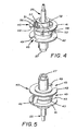
FIGURE 4 is a top perspective view of a universal collar according to the concepts of the present invention; and -
FIGURE 5 is a bottom perspective view of a universal collar according to the concepts of the present invention. - A dispenser, generally indicated by the
numeral 10, is depicted inFig. 1 of the drawings. Dispensers are widely available in the art and thedispenser 10 depicted inFig. 1 is one example. Thedispenser 10 generally includes a housing 11 that receives acontainer 20, such as a bag or bottle, that holds soap. The housing 11 may include a base 11a and a cover 11b which may be attached to each other in a clamshell-like fashion to facilitate replacement of anempty container 20. - As shown in
Fig. 2 , the base 11 a may define arecess 15 into which at least a portion of acontainer 20 is received. The base 11a may further include a shelf 17, which may be in the form of pair of shoulders that extend beneath thecontainer 20 on either side of itsneck 21. - A pump generally indicated by the
numeral 25, is typically attached to or formed integrally with thecontainer 20 for dispensing soap therefrom. As shown,pump 25 may extend downward fromcontainer 20 between shoulders 17. With reference toFigs. 3 and4 ,pump 25 may, for example, be attached to thecontainer 20 at aneck 21 extending downwardly fromcontainer 20, as by a threaded cap 22 that fits over thepump 25 and threads onto theneck 21. As shown, thepump 25 may include an annular rib 26 that rests against a shoulder 23 that extends radially inward from the cap 22. Thenozzle 27 of thepump 25 protrudes axially outward from the cap 22, and, in the example shown, is moved upward to dispense soap from thecontainer 20. - Returning to
Fig. 2 , it may be seen that base 11a may include slide guides 28 a nozzle locating bar (not shown) is mounted, on which to allow thepump 25 to be driven axially inward to pump soap from the container, the locator bar is movable with thenozzle 27 in the axial direction as it rides onslide guides 28. In this way, ahandle 12 that interacts with the locator bar may be used to move thenozzle 27 and dispense soap from thecontainer 20. In the example shown, thehandle 12 is pivotally attached to the cover 16 and includes rearwardly extending arms (not shown) that engage the locator bar to vertically displace thenozzle 27 and actuate thepump 25. - A
receiver 30 is located betweenslide guides 28 and is generally adapted to receive a collar key. As discussed previously, existing dispensers employ collar keys to ensure a unique fit between a givencontainer 20 and housing 11. Typically, the collar key carries a projecting key, and thereceiver 30 defines a keyway specific to a given collar key. For example, thereceiver 30, shown inFig. 2 , might have a keyway in the form of a vertical slot. A matching collar key would have a vertical key projecting therefrom and located such that the key would fit into the keyway on thereceiver 30. A collar key having the wrong key could not be fully inserted preventing its associated container from being used in that dispenser. As will be appreciated, to keymultiple containers 20 and housings 11, a variety of keyway arrangements have been established forindividual receivers 30. - With that in mind, a universal collar according to the concepts of the present invention is generally indicated by the
numeral 40 in the drawings, may be used to bypass the keying system. Before describing theuniversal collar 40 in detail, it should be understood that the term "universal," as used herein, refers to the universal collar's ability to work with more than onereceiver 30. - Returning to the
receiver 30, it may include akey plate 31 that is shaped to receive theuniversal collar 40 and, as shown for example inFig. 2 , may have a C-shaped key plate 31 defining a semi-circular opening into which theuniversal collar 40 may be received. Ashelf 32 may be formed inreceiver 30 and extend rearward above thekey plate 31. Theshelf 32 likekey plate 31 may be semicircular. In the example shown, theshelf 32 is recessed from a top surface 33 (FIGURE 3 ) ofreceiver 30 to generally form a semi-circular recessed area, with theshelf 32 extending radially outward of thekey plate 31. Locating tabs (not shown) may extend upwardly from a central portion of theshelf 32 to aid the user in positioning thecontainer 20 within therecess 15, as by the interaction with aprojection 34 formed on thecontainer 20. For example, aprojection 34 extending rearwardly from the center ofcontainer 20 may be aligned between the locating tabs and then inserted therebetween. Similarly, aramp 35 formed belowkeyplate 31 may help locate thecontainer 20 by interacting with collar universal 40, as described more completely below. In this way, theshelf 32 andramp 35 also provide some vertical support for thecontainer 20. - As best shown in
Figs. 4 and 5 , a universal collar according to the concepts of the present invention is generally indicated by the numeral 40. As shown, theuniversal collar 40 may be attached to thepump 25. It being understood that use of the word "attachment" includes integral formation of thepump 25 anduniversal collar 40. Theuniversal collar 40 generally includes afirst flange 41 and asecond flange 42 that each extend radially outward from thecollar body 43 orpump 25.Flanges clearance 45 for receipt of thekeyplate 31 therebetween. To that end,flanges keyplate 31. It will be appreciated thatflanges keyplate 31 and limit axial movement ofcontainer 20. - It will be appreciated that flanges may have any form suitable for contacting the
keyplate 31 and/orreceiver 30 to axially secure thecontainer 20. The generally planar horizontally extendingflanges receiver 30 orkeyplate 31, as previously described will be included in the use of the term "flange" herein. - In the example shown, a
vertical rib 46 extends between the first andsecond flanges vertical rib 46 may also limit rotation of theuniversal collar 40, which may result from deformation of thecontainer 20, by interacting with a surface of the cover 11b. In the example shown, to facilitate this use, the vertical rib is located on the forward side of theuniversal collar 40. -
Notches flanges rib 46. These notches provide a clearance for the locating tabs andramp 35, described above, found on thereceiver 30. Interaction between the edges of theflanges defining notches universal collar 40. - Since the
container 20 often containsprojections 34 used to locate a collar key on thecontainer 20, theuniversal collar 40 may include locatingrecesses top edge 53 ofuniversal collar 40 to receive theseprojections 34. - As best shown in
Fig. 3 , to attach theuniversal collar 40 and pump 25 to thecontainer 20, the bore 54 ofuniversal collar 40 may be provided withinternal threads 55 to thread theuniversal collar 40 onto theneck 21 of thecontainer 20. As discussed previously, theuniversal collar 40 may be attached in other ways as well. To allow for receipt of theprojection 34 oncontainer 20 as the universal collar (40) is rotated for attachment, therecesses FIGURE 4 , oneside 56 may be oblique and theother side 58 stand perpendicular to thebase 57 of therecess oblique side 56 provides clearance of the projection as theuniversal collar 40 is threaded ontocontainer 20, theperpendicular side 58 acts as a stop, squarely contacting theprojection 34, preventing rotation of theuniversal collar 40 that could cause misalignment between theuniversal collar 40 andcontainer 20. - In use, the
pump 25 withuniversal collar 40 attached, may be threaded onto theneck 21 of thecontainer 20 before inserting thecontainer 20 within the housing 11. As best shown inFig. 3 , the axially spacedflanges keyplate 31 to locate thepump 25 at the proper height and axially secure thecontainer 20 within thedispenser 10. The keyless rearward surface of thecollar 40 is able to fit against thekeyplate 31 allowing full insertion of thecontainer 15 regardless of any keyways K onkeyplate 31. Thus, container K may be used with any number ofkeyplates 31. - While a full and complete description of the invention has been set forth, it should be understood that modifications can be resorted to without departing from the scope of the appended claims.
Claims (8)
- An arrangement comprising a universal collar (40), a container (20) and a soap dispenser (10), the universal collar (40) being used in conjunction with the container (20) for securement of the container (20) within the dispenser (10) that has a housing (11) that defines a container recess and has a receiver (30) that includes a keyplate (31), the container (20) comprising a hollow body having a neck portion (21); and
the universal collar (40) comprising a body (43) defining a bore (54), wherein said universal collar (40) fits over said neck portion (21) and receives said neck portion within said bore, and a pair of generally horizontal planar flanges (41, 42) extending radially outward from said universal collar (40) and axially spaced from each other for receipt of the keyplate (31) therebetween;
characterized in that:the keyplate (31) is adapted to receive a collar key ensuring a unique fit between the container (20) and the housing (11), the unique fit being achieved by using keyways in the receiver (30) which correspond to projecting keys extending outwardly from a surface of the collar key; andthe universal collar (40) comprises a keyless rearward surface and is used in place of the collar key in order to bypass the keying system, said keyless rearward surface of the universal collar (40) being able to fit against the keyplate (31) allowing full insertion of the container (20) regardless of the keyways on the keyplate (31). - The arrangement of Claim 1, wherein said flanges (41, 42) are connected on a forward side of the universal collar (40) by a vertically extending rib (46).
- The arrangement of Claim 1, wherein at least one of said flanges (41, 42) defines a notch (48, 49) on a rearward side thereof for receiving a projecting portion of the dispenser (10).
- The arrangement of Claim 3, wherein said notch (48, 49) is centered within said flange on said rearward side.
- The arrangement of Claim 1, wherein said body (43) includes a top edge (53), said top edge defining a locating recess (51) for receipt of a projection (34) on the container (20), said recess having a base (57) and a pair of upstanding sides (56, 58), wherein said sides are circumferentially spaced from each other for receipt of the projection (34) therebetween.
- The arrangement of Claim 5, wherein one of said sides (56, 58) extends perpendicular to said base (57) and the other of said sides extends obliquely relative to said base (57).
- The arrangement of Claim 5, wherein said top edge (53) extends axially upward relative to said first flange (41) and extends in a circular fashion to circumscribe a portion of the container (20).
- The arrangement of Claim 4, wherein said flanges (41, 42) extend radially outward from said universal collar (40), each flange (41, 42) defining a notch that opens rearwardly relative to said universal collar (40).
Applications Claiming Priority (2)
| Application Number | Priority Date | Filing Date | Title |
|---|---|---|---|
| US10/693,567 US7950548B2 (en) | 2003-10-25 | 2003-10-25 | Universal collar |
| PCT/US2004/035448 WO2005039370A1 (en) | 2003-10-25 | 2004-10-25 | Universal collar |
Publications (2)
| Publication Number | Publication Date |
|---|---|
| EP1681971A1 EP1681971A1 (en) | 2006-07-26 |
| EP1681971B1 true EP1681971B1 (en) | 2015-09-30 |
Family
ID=34522426
Family Applications (1)
| Application Number | Title | Priority Date | Filing Date |
|---|---|---|---|
| EP04796427.5A Expired - Lifetime EP1681971B1 (en) | 2003-10-25 | 2004-10-25 | Universal collar |
Country Status (13)
| Country | Link |
|---|---|
| US (1) | US7950548B2 (en) |
| EP (1) | EP1681971B1 (en) |
| JP (1) | JP4613169B2 (en) |
| KR (1) | KR101158131B1 (en) |
| CN (1) | CN100518606C (en) |
| AU (1) | AU2004283747B2 (en) |
| BR (1) | BRPI0415864A (en) |
| CA (1) | CA2542430C (en) |
| DK (1) | DK1681971T3 (en) |
| ES (1) | ES2552093T3 (en) |
| PT (1) | PT1681971E (en) |
| TW (1) | TWI255175B (en) |
| WO (1) | WO2005039370A1 (en) |
Families Citing this family (20)
| Publication number | Priority date | Publication date | Assignee | Title |
|---|---|---|---|---|
| US8336740B1 (en) | 2005-11-02 | 2012-12-25 | Daansen Warren S | Fluid dispenser and pump adapter system therefor |
| US8499981B2 (en) * | 2008-02-08 | 2013-08-06 | Gojo Industries, Inc. | Bifurcated stem foam pump |
| US8485395B2 (en) * | 2011-08-02 | 2013-07-16 | Gojo Industries, Inc. | Dispenser lockout mechanism |
| US9027797B2 (en) | 2013-01-23 | 2015-05-12 | Gojo Industries, Inc. | Shield for a fluid dispenser |
| US9573736B2 (en) * | 2013-07-03 | 2017-02-21 | Scholle Ipn Corporation | Connector assembly for a self sealing fitment |
| US10123661B2 (en) * | 2013-11-27 | 2018-11-13 | Archer Manufacturing, Inc. | Tamper-proof and ligation resistant dispenser for liquids |
| US10743720B2 (en) | 2013-11-27 | 2020-08-18 | Archer Manufacturing, Inc. | Tamper-resistant devices and systems for wall-mounted dispensers |
| US10743721B2 (en) | 2013-11-27 | 2020-08-18 | Archer Manufacturing, Inc. | Tamper-resistant devices and systems for wall-mounted dispensers |
| US10034584B2 (en) | 2014-03-04 | 2018-07-31 | Gojo Industries, Inc. | Fluid dispenser and fluid refill system for fluid dispenser |
| US11058261B2 (en) | 2015-07-15 | 2021-07-13 | Gojo Industries, Inc. | Bulk refill protection sensor for dispensing system |
| CN106933134A (en) * | 2015-12-31 | 2017-07-07 | 中核陕西铀浓缩有限公司 | Multi-channel intelligent main frame frequency signal detects box |
| CA3010608C (en) * | 2016-01-05 | 2024-09-17 | Gojo Industries, Inc. | Systems and methods for monitoring and controlling dispenser fluid refill |
| USD811770S1 (en) * | 2016-06-21 | 2018-03-06 | Gojo Industries, Inc. | Wall mounted dispenser cabinet |
| USD862112S1 (en) | 2016-09-21 | 2019-10-08 | Gojo Industries, Inc. | Dispenser |
| USD809821S1 (en) | 2016-10-31 | 2018-02-13 | Gojo Industries, Inc. | Wall mounted dispenser cabinet |
| USD815457S1 (en) | 2016-10-31 | 2018-04-17 | Gojo Industries, Inc. | Wall mounted dispenser cabinet |
| US10278549B1 (en) | 2016-10-31 | 2019-05-07 | Gpcp Ip Holdings Llc | Counter-mounted skincare product dispenser |
| USD820614S1 (en) | 2016-11-28 | 2018-06-19 | Gojo Industries, Inc. | Wall mounted dispenser cabinet |
| US10561282B2 (en) | 2017-12-21 | 2020-02-18 | Speakman Company | Ligature-resistant dispenser |
| USD982929S1 (en) | 2021-10-07 | 2023-04-11 | S. C. Johnson & Son, Inc. | Dispenser |
Family Cites Families (25)
| Publication number | Priority date | Publication date | Assignee | Title |
|---|---|---|---|---|
| US2091518A (en) * | 1935-05-27 | 1937-08-31 | Nesbitt Fruit Products Inc | Dispenser for liquids |
| US2707069A (en) * | 1954-08-04 | 1955-04-26 | G & W Mfg Company Inc | Syrup dispenser |
| US3173579A (en) * | 1964-03-04 | 1965-03-16 | Corrugated Container Company | Disposable type dispensing container package |
| AU7609181A (en) * | 1980-10-09 | 1982-04-22 | Tobacco Research And Development Institute Limited | Tap for a composite liquid container |
| DE3042517A1 (en) * | 1980-11-11 | 1982-06-16 | Siemens AG, 1000 Berlin und 8000 München | LIQUID CRYSTAL DISPLAY |
| US4946072A (en) * | 1989-02-16 | 1990-08-07 | Johnson & Johnson Medical, Inc. | Container for surgical soap dispenser |
| US4974753A (en) * | 1989-11-06 | 1990-12-04 | James River Corporation | Liquid dispenser container and holder system |
| US5033657A (en) * | 1990-06-27 | 1991-07-23 | James River Corporation | Adjustable stroke pump dispenser |
| US5083678A (en) * | 1990-08-27 | 1992-01-28 | James River Corporation | Collapsible dispenser bottle |
| IT221905Z2 (en) * | 1991-06-06 | 1994-12-06 | Q T S Srl | DISPENSER GROUP FOR LIQUID SOAP DISTRIBUTORS |
| GB9112989D0 (en) | 1991-06-17 | 1991-08-07 | Genzyme Uk Ltd | Preparation of oligosaccharide derivatives |
| US5383580A (en) * | 1993-04-05 | 1995-01-24 | Winder; Gary C. | Aerosol spray can adaptor |
| US5377876A (en) * | 1993-04-14 | 1995-01-03 | Smernoff; Ronald | Disposable container for pourable materials having an interlocking spout |
| CA2102016C (en) * | 1993-10-29 | 1995-08-15 | Heiner Ophardt | Liquid soap dispenser for simplified replacement of soap reservoir |
| US5439144A (en) * | 1993-12-27 | 1995-08-08 | Steiner Company, Inc. | Liquid soap dispensing system |
| CN2221926Y (en) * | 1995-02-09 | 1996-03-13 | 丰勤实业有限公司 | Soap dispenser |
| CA2146102C (en) * | 1995-03-31 | 2000-07-25 | Hermann Ophardt | Bag fluid dispenser |
| US5725131A (en) * | 1996-05-24 | 1998-03-10 | Gojo Industries, Inc. | Powder dispensing dispenser valve and dispensing assembly |
| US6082586A (en) * | 1998-03-30 | 2000-07-04 | Deb Ip Limited | Liquid dispenser for dispensing foam |
| CN2402621Y (en) * | 1999-11-09 | 2000-10-25 | 谭奇锋 | Liquid packaging bottle |
| CA2341659C (en) * | 2001-03-20 | 2007-08-07 | Hygiene-Technik Inc. | Liquid dispenser for dispensing foam |
| US6450214B1 (en) * | 2001-08-31 | 2002-09-17 | 3M Innovative Properties Company | Gravity feed fluid dispensing valve |
| USD480639S1 (en) * | 2002-07-25 | 2003-10-14 | Joseph S. Kanfer | Security collar for a container closure |
| US7798370B2 (en) * | 2003-10-25 | 2010-09-21 | Gojo Industries, Inc. | Universal collar key |
| US7503465B2 (en) * | 2003-10-25 | 2009-03-17 | Joseph S. Kanfer | Universal adapter clip |
-
2003
- 2003-10-25 US US10/693,567 patent/US7950548B2/en not_active Expired - Fee Related
-
2004
- 2004-10-25 CN CNB2004800315152A patent/CN100518606C/en not_active Expired - Fee Related
- 2004-10-25 ES ES04796427.5T patent/ES2552093T3/en not_active Expired - Lifetime
- 2004-10-25 KR KR1020067007826A patent/KR101158131B1/en not_active Expired - Fee Related
- 2004-10-25 BR BRPI0415864-4A patent/BRPI0415864A/en active Search and Examination
- 2004-10-25 WO PCT/US2004/035448 patent/WO2005039370A1/en not_active Ceased
- 2004-10-25 EP EP04796427.5A patent/EP1681971B1/en not_active Expired - Lifetime
- 2004-10-25 DK DK04796427.5T patent/DK1681971T3/en active
- 2004-10-25 JP JP2006536924A patent/JP4613169B2/en not_active Expired - Fee Related
- 2004-10-25 PT PT47964275T patent/PT1681971E/en unknown
- 2004-10-25 CA CA2542430A patent/CA2542430C/en not_active Expired - Fee Related
- 2004-10-25 AU AU2004283747A patent/AU2004283747B2/en not_active Ceased
- 2004-10-26 TW TW093132643A patent/TWI255175B/en not_active IP Right Cessation
Also Published As
| Publication number | Publication date |
|---|---|
| WO2005039370A1 (en) | 2005-05-06 |
| CN100518606C (en) | 2009-07-29 |
| ES2552093T3 (en) | 2015-11-25 |
| CA2542430C (en) | 2012-08-07 |
| CN1870925A (en) | 2006-11-29 |
| KR20060128867A (en) | 2006-12-14 |
| CA2542430A1 (en) | 2005-05-06 |
| TW200526162A (en) | 2005-08-16 |
| US7950548B2 (en) | 2011-05-31 |
| KR101158131B1 (en) | 2012-06-19 |
| US20050087563A1 (en) | 2005-04-28 |
| EP1681971A1 (en) | 2006-07-26 |
| BRPI0415864A (en) | 2007-01-09 |
| JP4613169B2 (en) | 2011-01-12 |
| PT1681971E (en) | 2016-01-04 |
| AU2004283747A1 (en) | 2005-05-06 |
| TWI255175B (en) | 2006-05-21 |
| AU2004283747B2 (en) | 2011-06-16 |
| JP2007509014A (en) | 2007-04-12 |
| DK1681971T3 (en) | 2015-12-14 |
Similar Documents
| Publication | Publication Date | Title |
|---|---|---|
| AU2004283747B2 (en) | Universal collar | |
| US7798370B2 (en) | Universal collar key | |
| EP1677655B1 (en) | Universal adaptor clip | |
| JP2007508915A5 (en) | ||
| JP2007509014A5 (en) | ||
| JP2007511257A5 (en) | ||
| HK1096008B (en) | Universal adaptor clip | |
| HK1096009B (en) | Universal collar key |
Legal Events
| Date | Code | Title | Description |
|---|---|---|---|
| PUAI | Public reference made under article 153(3) epc to a published international application that has entered the european phase |
Free format text: ORIGINAL CODE: 0009012 |
|
| 17P | Request for examination filed |
Effective date: 20060515 |
|
| AK | Designated contracting states |
Kind code of ref document: A1 Designated state(s): AT BE BG CH CY CZ DE DK EE ES FI FR GB GR HU IE IT LI LU MC NL PL PT RO SE SI SK TR |
|
| DAX | Request for extension of the european patent (deleted) | ||
| 17Q | First examination report despatched |
Effective date: 20070412 |
|
| GRAP | Despatch of communication of intention to grant a patent |
Free format text: ORIGINAL CODE: EPIDOSNIGR1 |
|
| INTG | Intention to grant announced |
Effective date: 20150504 |
|
| GRAS | Grant fee paid |
Free format text: ORIGINAL CODE: EPIDOSNIGR3 |
|
| GRAA | (expected) grant |
Free format text: ORIGINAL CODE: 0009210 |
|
| AK | Designated contracting states |
Kind code of ref document: B1 Designated state(s): AT BE BG CH CY CZ DE DK EE ES FI FR GB GR HU IE IT LI LU MC NL PL PT RO SE SI SK TR |
|
| REG | Reference to a national code |
Ref country code: CH Ref legal event code: EP Ref country code: GB Ref legal event code: FG4D |
|
| REG | Reference to a national code |
Ref country code: AT Ref legal event code: REF Ref document number: 751874 Country of ref document: AT Kind code of ref document: T Effective date: 20151015 |
|
| REG | Reference to a national code |
Ref country code: IE Ref legal event code: FG4D |
|
| REG | Reference to a national code |
Ref country code: FR Ref legal event code: PLFP Year of fee payment: 12 |
|
| REG | Reference to a national code |
Ref country code: DE Ref legal event code: R096 Ref document number: 602004047997 Country of ref document: DE |
|
| REG | Reference to a national code |
Ref country code: ES Ref legal event code: FG2A Ref document number: 2552093 Country of ref document: ES Kind code of ref document: T3 Effective date: 20151125 |
|
| REG | Reference to a national code |
Ref country code: DK Ref legal event code: T3 Effective date: 20151207 |
|
| REG | Reference to a national code |
Ref country code: SE Ref legal event code: TRGR |
|
| REG | Reference to a national code |
Ref country code: PT Ref legal event code: SC4A Free format text: AVAILABILITY OF NATIONAL TRANSLATION Effective date: 20151204 |
|
| REG | Reference to a national code |
Ref country code: NL Ref legal event code: FP |
|
| PG25 | Lapsed in a contracting state [announced via postgrant information from national office to epo] |
Ref country code: GR Free format text: LAPSE BECAUSE OF FAILURE TO SUBMIT A TRANSLATION OF THE DESCRIPTION OR TO PAY THE FEE WITHIN THE PRESCRIBED TIME-LIMIT Effective date: 20151231 Ref country code: FI Free format text: LAPSE BECAUSE OF FAILURE TO SUBMIT A TRANSLATION OF THE DESCRIPTION OR TO PAY THE FEE WITHIN THE PRESCRIBED TIME-LIMIT Effective date: 20150930 |
|
| REG | Reference to a national code |
Ref country code: AT Ref legal event code: MK05 Ref document number: 751874 Country of ref document: AT Kind code of ref document: T Effective date: 20150930 |
|
| PG25 | Lapsed in a contracting state [announced via postgrant information from national office to epo] |
Ref country code: CZ Free format text: LAPSE BECAUSE OF FAILURE TO SUBMIT A TRANSLATION OF THE DESCRIPTION OR TO PAY THE FEE WITHIN THE PRESCRIBED TIME-LIMIT Effective date: 20150930 Ref country code: SK Free format text: LAPSE BECAUSE OF FAILURE TO SUBMIT A TRANSLATION OF THE DESCRIPTION OR TO PAY THE FEE WITHIN THE PRESCRIBED TIME-LIMIT Effective date: 20150930 Ref country code: EE Free format text: LAPSE BECAUSE OF FAILURE TO SUBMIT A TRANSLATION OF THE DESCRIPTION OR TO PAY THE FEE WITHIN THE PRESCRIBED TIME-LIMIT Effective date: 20150930 |
|
| PG25 | Lapsed in a contracting state [announced via postgrant information from national office to epo] |
Ref country code: AT Free format text: LAPSE BECAUSE OF FAILURE TO SUBMIT A TRANSLATION OF THE DESCRIPTION OR TO PAY THE FEE WITHIN THE PRESCRIBED TIME-LIMIT Effective date: 20150930 Ref country code: PL Free format text: LAPSE BECAUSE OF FAILURE TO SUBMIT A TRANSLATION OF THE DESCRIPTION OR TO PAY THE FEE WITHIN THE PRESCRIBED TIME-LIMIT Effective date: 20150930 Ref country code: RO Free format text: LAPSE BECAUSE OF FAILURE TO SUBMIT A TRANSLATION OF THE DESCRIPTION OR TO PAY THE FEE WITHIN THE PRESCRIBED TIME-LIMIT Effective date: 20150930 |
|
| REG | Reference to a national code |
Ref country code: CH Ref legal event code: PL |
|
| PG25 | Lapsed in a contracting state [announced via postgrant information from national office to epo] |
Ref country code: MC Free format text: LAPSE BECAUSE OF FAILURE TO SUBMIT A TRANSLATION OF THE DESCRIPTION OR TO PAY THE FEE WITHIN THE PRESCRIBED TIME-LIMIT Effective date: 20150930 |
|
| REG | Reference to a national code |
Ref country code: DE Ref legal event code: R097 Ref document number: 602004047997 Country of ref document: DE |
|
| PG25 | Lapsed in a contracting state [announced via postgrant information from national office to epo] |
Ref country code: CH Free format text: LAPSE BECAUSE OF NON-PAYMENT OF DUE FEES Effective date: 20151031 Ref country code: LI Free format text: LAPSE BECAUSE OF NON-PAYMENT OF DUE FEES Effective date: 20151031 |
|
| PLBE | No opposition filed within time limit |
Free format text: ORIGINAL CODE: 0009261 |
|
| STAA | Information on the status of an ep patent application or granted ep patent |
Free format text: STATUS: NO OPPOSITION FILED WITHIN TIME LIMIT |
|
| 26N | No opposition filed |
Effective date: 20160701 |
|
| PGFP | Annual fee paid to national office [announced via postgrant information from national office to epo] |
Ref country code: IE Payment date: 20160907 Year of fee payment: 13 |
|
| PG25 | Lapsed in a contracting state [announced via postgrant information from national office to epo] |
Ref country code: SI Free format text: LAPSE BECAUSE OF FAILURE TO SUBMIT A TRANSLATION OF THE DESCRIPTION OR TO PAY THE FEE WITHIN THE PRESCRIBED TIME-LIMIT Effective date: 20150930 |
|
| PGFP | Annual fee paid to national office [announced via postgrant information from national office to epo] |
Ref country code: PT Payment date: 20160908 Year of fee payment: 13 |
|
| PGFP | Annual fee paid to national office [announced via postgrant information from national office to epo] |
Ref country code: DK Payment date: 20161129 Year of fee payment: 13 Ref country code: NL Payment date: 20161005 Year of fee payment: 13 |
|
| REG | Reference to a national code |
Ref country code: FR Ref legal event code: PLFP Year of fee payment: 13 |
|
| PGFP | Annual fee paid to national office [announced via postgrant information from national office to epo] |
Ref country code: BE Payment date: 20161129 Year of fee payment: 13 Ref country code: ES Payment date: 20161003 Year of fee payment: 13 Ref country code: IT Payment date: 20161129 Year of fee payment: 13 Ref country code: SE Payment date: 20161129 Year of fee payment: 13 |
|
| PGFP | Annual fee paid to national office [announced via postgrant information from national office to epo] |
Ref country code: DE Payment date: 20170206 Year of fee payment: 13 |
|
| PG25 | Lapsed in a contracting state [announced via postgrant information from national office to epo] |
Ref country code: BG Free format text: LAPSE BECAUSE OF FAILURE TO SUBMIT A TRANSLATION OF THE DESCRIPTION OR TO PAY THE FEE WITHIN THE PRESCRIBED TIME-LIMIT Effective date: 20150930 Ref country code: HU Free format text: LAPSE BECAUSE OF FAILURE TO SUBMIT A TRANSLATION OF THE DESCRIPTION OR TO PAY THE FEE WITHIN THE PRESCRIBED TIME-LIMIT; INVALID AB INITIO Effective date: 20041025 |
|
| PG25 | Lapsed in a contracting state [announced via postgrant information from national office to epo] |
Ref country code: CY Free format text: LAPSE BECAUSE OF FAILURE TO SUBMIT A TRANSLATION OF THE DESCRIPTION OR TO PAY THE FEE WITHIN THE PRESCRIBED TIME-LIMIT Effective date: 20150930 |
|
| PG25 | Lapsed in a contracting state [announced via postgrant information from national office to epo] |
Ref country code: TR Free format text: LAPSE BECAUSE OF FAILURE TO SUBMIT A TRANSLATION OF THE DESCRIPTION OR TO PAY THE FEE WITHIN THE PRESCRIBED TIME-LIMIT Effective date: 20150930 |
|
| REG | Reference to a national code |
Ref country code: FR Ref legal event code: PLFP Year of fee payment: 14 |
|
| PG25 | Lapsed in a contracting state [announced via postgrant information from national office to epo] |
Ref country code: LU Free format text: LAPSE BECAUSE OF NON-PAYMENT OF DUE FEES Effective date: 20151025 |
|
| REG | Reference to a national code |
Ref country code: DE Ref legal event code: R119 Ref document number: 602004047997 Country of ref document: DE |
|
| REG | Reference to a national code |
Ref country code: DK Ref legal event code: EBP Effective date: 20171031 |
|
| REG | Reference to a national code |
Ref country code: SE Ref legal event code: EUG |
|
| REG | Reference to a national code |
Ref country code: NL Ref legal event code: MM Effective date: 20171101 |
|
| REG | Reference to a national code |
Ref country code: IE Ref legal event code: MM4A |
|
| PG25 | Lapsed in a contracting state [announced via postgrant information from national office to epo] |
Ref country code: PT Free format text: LAPSE BECAUSE OF NON-PAYMENT OF DUE FEES Effective date: 20180426 Ref country code: NL Free format text: LAPSE BECAUSE OF NON-PAYMENT OF DUE FEES Effective date: 20171101 Ref country code: DE Free format text: LAPSE BECAUSE OF NON-PAYMENT OF DUE FEES Effective date: 20180501 |
|
| REG | Reference to a national code |
Ref country code: BE Ref legal event code: FP Effective date: 20151126 Ref country code: BE Ref legal event code: MM Effective date: 20171031 |
|
| PG25 | Lapsed in a contracting state [announced via postgrant information from national office to epo] |
Ref country code: BE Free format text: LAPSE BECAUSE OF NON-PAYMENT OF DUE FEES Effective date: 20171031 Ref country code: SE Free format text: LAPSE BECAUSE OF NON-PAYMENT OF DUE FEES Effective date: 20171026 |
|
| REG | Reference to a national code |
Ref country code: FR Ref legal event code: PLFP Year of fee payment: 15 |
|
| PG25 | Lapsed in a contracting state [announced via postgrant information from national office to epo] |
Ref country code: IT Free format text: LAPSE BECAUSE OF NON-PAYMENT OF DUE FEES Effective date: 20171025 Ref country code: IE Free format text: LAPSE BECAUSE OF NON-PAYMENT OF DUE FEES Effective date: 20171025 |
|
| PG25 | Lapsed in a contracting state [announced via postgrant information from national office to epo] |
Ref country code: DK Free format text: LAPSE BECAUSE OF NON-PAYMENT OF DUE FEES Effective date: 20171031 |
|
| REG | Reference to a national code |
Ref country code: ES Ref legal event code: FD2A Effective date: 20181221 |
|
| PG25 | Lapsed in a contracting state [announced via postgrant information from national office to epo] |
Ref country code: ES Free format text: LAPSE BECAUSE OF NON-PAYMENT OF DUE FEES Effective date: 20171026 |
|
| PGFP | Annual fee paid to national office [announced via postgrant information from national office to epo] |
Ref country code: GB Payment date: 20211027 Year of fee payment: 18 |
|
| PGFP | Annual fee paid to national office [announced via postgrant information from national office to epo] |
Ref country code: FR Payment date: 20211025 Year of fee payment: 18 |
|
| GBPC | Gb: european patent ceased through non-payment of renewal fee |
Effective date: 20221025 |
|
| PG25 | Lapsed in a contracting state [announced via postgrant information from national office to epo] |
Ref country code: FR Free format text: LAPSE BECAUSE OF NON-PAYMENT OF DUE FEES Effective date: 20221031 |
|
| PG25 | Lapsed in a contracting state [announced via postgrant information from national office to epo] |
Ref country code: GB Free format text: LAPSE BECAUSE OF NON-PAYMENT OF DUE FEES Effective date: 20221025 |