EP1681806B1 - New WLAN TDM protocol - Google Patents
New WLAN TDM protocol Download PDFInfo
- Publication number
- EP1681806B1 EP1681806B1 EP06000610A EP06000610A EP1681806B1 EP 1681806 B1 EP1681806 B1 EP 1681806B1 EP 06000610 A EP06000610 A EP 06000610A EP 06000610 A EP06000610 A EP 06000610A EP 1681806 B1 EP1681806 B1 EP 1681806B1
- Authority
- EP
- European Patent Office
- Prior art keywords
- wireless network
- network device
- ifs time
- time
- data packet
- Prior art date
- Legal status (The legal status is an assumption and is not a legal conclusion. Google has not performed a legal analysis and makes no representation as to the accuracy of the status listed.)
- Active
Links
Images


Classifications
-
- H—ELECTRICITY
- H04—ELECTRIC COMMUNICATION TECHNIQUE
- H04W—WIRELESS COMMUNICATION NETWORKS
- H04W52/00—Power management, e.g. TPC [Transmission Power Control], power saving or power classes
- H04W52/02—Power saving arrangements
- H04W52/0203—Power saving arrangements in the radio access network or backbone network of wireless communication networks
-
- H—ELECTRICITY
- H04—ELECTRIC COMMUNICATION TECHNIQUE
- H04W—WIRELESS COMMUNICATION NETWORKS
- H04W48/00—Access restriction; Network selection; Access point selection
-
- H—ELECTRICITY
- H04—ELECTRIC COMMUNICATION TECHNIQUE
- H04W—WIRELESS COMMUNICATION NETWORKS
- H04W74/00—Wireless channel access, e.g. scheduled or random access
-
- H—ELECTRICITY
- H04—ELECTRIC COMMUNICATION TECHNIQUE
- H04W—WIRELESS COMMUNICATION NETWORKS
- H04W4/00—Services specially adapted for wireless communication networks; Facilities therefor
- H04W4/06—Selective distribution of broadcast services, e.g. multimedia broadcast multicast service [MBMS]; Services to user groups; One-way selective calling services
-
- H—ELECTRICITY
- H04—ELECTRIC COMMUNICATION TECHNIQUE
- H04W—WIRELESS COMMUNICATION NETWORKS
- H04W48/00—Access restriction; Network selection; Access point selection
- H04W48/08—Access restriction or access information delivery, e.g. discovery data delivery
-
- H—ELECTRICITY
- H04—ELECTRIC COMMUNICATION TECHNIQUE
- H04W—WIRELESS COMMUNICATION NETWORKS
- H04W48/00—Access restriction; Network selection; Access point selection
- H04W48/16—Discovering, processing access restriction or access information
-
- H—ELECTRICITY
- H04—ELECTRIC COMMUNICATION TECHNIQUE
- H04W—WIRELESS COMMUNICATION NETWORKS
- H04W56/00—Synchronisation arrangements
-
- H—ELECTRICITY
- H04—ELECTRIC COMMUNICATION TECHNIQUE
- H04W—WIRELESS COMMUNICATION NETWORKS
- H04W8/00—Network data management
- H04W8/26—Network addressing or numbering for mobility support
-
- H—ELECTRICITY
- H04—ELECTRIC COMMUNICATION TECHNIQUE
- H04W—WIRELESS COMMUNICATION NETWORKS
- H04W80/00—Wireless network protocols or protocol adaptations to wireless operation
-
- H—ELECTRICITY
- H04—ELECTRIC COMMUNICATION TECHNIQUE
- H04W—WIRELESS COMMUNICATION NETWORKS
- H04W84/00—Network topologies
- H04W84/02—Hierarchically pre-organised networks, e.g. paging networks, cellular networks, WLAN [Wireless Local Area Network] or WLL [Wireless Local Loop]
- H04W84/10—Small scale networks; Flat hierarchical networks
- H04W84/12—WLAN [Wireless Local Area Networks]
-
- Y—GENERAL TAGGING OF NEW TECHNOLOGICAL DEVELOPMENTS; GENERAL TAGGING OF CROSS-SECTIONAL TECHNOLOGIES SPANNING OVER SEVERAL SECTIONS OF THE IPC; TECHNICAL SUBJECTS COVERED BY FORMER USPC CROSS-REFERENCE ART COLLECTIONS [XRACs] AND DIGESTS
- Y02—TECHNOLOGIES OR APPLICATIONS FOR MITIGATION OR ADAPTATION AGAINST CLIMATE CHANGE
- Y02D—CLIMATE CHANGE MITIGATION TECHNOLOGIES IN INFORMATION AND COMMUNICATION TECHNOLOGIES [ICT], I.E. INFORMATION AND COMMUNICATION TECHNOLOGIES AIMING AT THE REDUCTION OF THEIR OWN ENERGY USE
- Y02D30/00—Reducing energy consumption in communication networks
- Y02D30/70—Reducing energy consumption in communication networks in wireless communication networks
Definitions
- the present invention relates to wireless networks, and more particularly to reducing power consumption of wireless network devices and improving network utilization.
- IEEE standards 802.11, 802.11a, 802.11b, 802.11g, 802.11h, 802.11n, 802.16, and 802.20 define several different standards for configuring wireless networks and devices. According to these standards, wireless network devices may be operated in either an infrastructure mode or an ad-hoc mode.
- the wireless network devices or client stations communicate with each other through an access point.
- the wireless network devices communicate directly with each other and do not employ an access point.
- the term client station or mobile station may not necessarily mean that a wireless network device is actually mobile.
- a desktop computer that is not mobile may incorporate a wireless network device and operate as a mobile station or client station.
- a wireless network that operates in the infrastructure mode includes an access point (AP) and at least one client station that communicates with the AP.
- the wireless network may operate in an infrastructure mode. Since the client stations are often battery powered, it is important to minimize power consumption to preserve battery life. Therefore, some client stations implement a low power mode and an active, or "awake,” mode. During the active mode, the client station transmits and/or receives data. During the low power mode, the client station shuts down components and/or alters operation to conserve power. Usually, the client station is not able to transmit or receive data during the lower power mode.
- Wireless network devices may be implemented by a system on chip (SOC) circuit that includes a baseband processor (BBP), a medium access controller (MAC) device, a host interface, and one or more processors.
- a host communicates with the wireless network device via the host interface.
- the SOC circuit may include a radio frequency (RF) transceiver or the RF transceiver may be located externally.
- the host interface may include a peripheral component interface (PCI) although other types of interfaces may be used.
- PCI peripheral component interface
- a power management device controls and selects different operating modes of the client stations. During operation, the power management device instructs some of the modules to transition to a low power mode to conserve power. Additional information may be found in U.S. Patent Application Serial Nos. 10/650,887, filed on August 28, 2003 , 10/665,252, filed on September 19, 2003 , and 11/070,481 filed on March 2, 2005 .
- the first wireless network 10 is illustrated in an infrastructure mode as defined by IEEE 802.11 and other future wireless standards.
- the first wireless network 10 includes one or more client stations 12 and one or more access points (AP) 14.
- the client station 12 and the AP 14 transmit and receive wireless signals 16.
- the AP 14 is a node in a network 18.
- the network 18 may be a local area network (LAN), a wide area network (WAN), or another network configuration.
- the network 18 may include other nodes such as a server 20 and may be connected to a distributed communications system 22 such as the Internet.
- the client station 12 does not continuously transmit data to or receive data from the AP 14. Therefore, the client station 12 implements a power savings mode when the client station 12 and the AP 14 do not have data to exchange. Data commonly remains intact in a network for a predetermined amount of time before it is dropped.
- the incorporated IEEE standards provide the opportunity for the client station 12 to inform the AP 14 when the client station 12 is entering a low power mode (and will not be capable of receiving data for a predetermined period). After notifying the AP 14, the client station 12 transitions to the low power mode. During the low power period, the AP 14 buffers data that is intended to be transmitted to the client station 12. Following the low power period, the client station 12 powers up and receives beacon transmissions from the AP 14. If the beacon transmissions indicate that the AP 14 has data for the client station 12, or the host processor of the client station 12 indicates it has data to transmit, the client station 12 remains active. Otherwise, the client station 12 enters the low power mode again.
- the AP 14 attempts to transmit a beacon at a target beacon transmission time (TBTT). Before the AP 14 sends out a beacon transmission, the AP 14 determines whether other devices are currently transmitting data so that other devices are able to use the network.
- the client station 12 transitions to the active mode prior to a beacon transmission to queue frames to transmit to the AP 14 in a buffer.
- the AP 14 can exchange frames with one or more client stations 12 in a deterministic order.
- the AP 14 and the clients stations 12 may exchange data according to Time Division Multiplexed (TDM) protocol.
- TDM Time Division Multiplexed
- the use of TDM protocol minimizes collisions that may occur when one or more of the client stations 12 attempt to transmit data to the AP 14 simultaneously.
- other wireless networks that are located near the first wireless network 10 may not operate according to the above-described TDM protocol. As such, collisions may occur between the other wireless networks and the first wireless network 10.
- each client station 12 may wait for a random period prior to transmitting. This random period, or backoff period, reduces the likelihood that multiple client stations will attempt to transmit simultaneously.
- a wireless network that implements the random backoff period has improved collision avoidance over a wireless network that implements a pure TOM scheme when multiple networks exist in an overlapping region.
- random backoff but does not guarantee collision avoidance.
- collision avoidance is critical. For example, wireless networks that exchange multicast data typically do not include a positive acknowledgement feature. In other words, a transmitting station does not receive acknowledgement from a receiving station that the data was correctly received. Further, as a result of the random backoff periods, the time required for all stations in the wireless network to complete a set of frame exchanges is increased.
- a second wireless network 24 operates in an ad-hoc mode.
- the second wireless network 24 includes multiple client stations 26-1, 26-2, and 26-3 that transmit and receive wireless signals 28.
- the client stations 26-1, 26-2, and 26-3 collectively form a LAN and communicate directly with each other.
- the client stations 26-1, 26-2, and 26-3 are not necessarily connected to another network.
- the client stations 26-1, 26-2, and 26-3 do not continuously transmit data to and receive data from each other.
- the client stations 26 implement a power savings mode when one of the client stations 26-1 does not have data to exchange with the other client stations 26-2 and 26-3.
- the client stations 26-1, 26-2, and 26-3 are not required to buffer data as performed in the AP.
- the client station 26-1 transmits the beacon to the other client stations 26-2 and 26-3.
- the client stations 26-2 and 26-3 transition to the active mode prior to the beacon transmission.
- each client station 26 transmits data in a deterministic order.
- the client stations 26 may transmit data sequentially.
- EP-A-1 233 574 discloses a wireless network device in a wireless network that includes a plurality of wireless network devices comprising an RF transceiver for transmitting and receiving data packets and for periodically transmitting and receiving a beacon.
- the system further comprises a control module that communicates with the RF transceiver for selecting one of a default IFS time and a second IFS time based on a data packet received for a second wireless network device.
- a wireless network device comprises an RF transceiver that transmits and receives data packets and that periodically transmits or receives a beacon.
- a control module communicates with the RF transceiver, determines a default interframe space (IFS) time based on the beacon, and that selects one of the default IFS time and a second IFS time that is less than or equal to the default IFS time based on a number of data packets received after the beacon.
- IFS interframe space
- the beacon includes data that is indicative of a transmission position m for the wireless network device.
- the control module selects the second IFS time when the RF transceiver receives m-1 data packets.
- the control module selects the default IFS time when the RF transceiver has received fewer than m-1 data packets.
- control module includes an IFS timer that is reset when data packets are received.
- the RF transceiver transmits a data packet after one of the default IFS time and the second IFS time.
- a power management module that transitions the wireless network device between an active mode and an inactive mode. The power management module transitions the wireless network device to the active mode prior to a scheduled beacon time. The power management module transitions the wireless network device to the inactive mode after the RF transceiver transmits a data packet.
- a wireless network comprising the wireless network device further comprises N-1 other wireless network devices. The power management module transitions the wireless network device to the inactive mode after all of the N wireless network devices transmit a data packet.
- a wireless network comprises a plurality of the wireless network devices.
- the power management module transitions the wireless network devices to the inactive mode after an idle time on the network that is greater than a largest available IFS time.
- One of the wireless network devices is a coordinator that periodically transmits the beacon to the plurality of wireless network devices.
- a wireless network device comprises transmitting and receiving means for transmitting and receiving data packets and for periodically transmitting or receiving a beacon.
- the wireless network device comprises control means for communicating with the transmitting and receiving means, for determining a default interframe space (IFS) time based on the beacon, and for selecting one of the default IFS time and a second IFS time that is less than or equal to the default IFS time based on a number of data packets received after the beacon.
- IFS interframe space
- the beacon includes data that is indicative of a transmission position m for the wireless network device.
- the control means selects the second IFS time when the transmitting and receiving means receives m-1 data packets.
- the control means selects the default IFS time when the transmitting and receiving means has received fewer than m-1 data packets.
- the control means includes timing means for monitoring IFS times. The timing means is reset when data packets are received and the transmitting and receiving means transmits a data packet after one of the default IFS time and the second IFS time.
- the wireless network device further comprises power management means for transitioning the wireless network device between an active mode and an inactive mode.
- the power management means transitions the wireless network device to the active mode prior to a scheduled beacon time.
- the power management means transitions the wireless network device to the inactive mode after the transmitting and receiving means transmits a data packet.
- a wireless network comprising the wireless network device further comprises N-1 other wireless network devices.
- the power management means transitions the wireless network device to the inactive mode after all of the N wireless network devices transmit a data packet.
- the power management means transitions the wireless network devices to the inactive mode after an idle time on the network that is greater than a largest available IFS time.
- One of the wireless network devices is a coordinator that periodically transmits the beacon to the plurality of wireless network devices.
- a method for transmitting and receiving data with a wireless network device comprises at least one of transmitting and receiving data packets, at least one of periodically receiving and transmitting a beacon, determining a default interframe space (IFS) time based on the beacon, and selecting one of the default IFS time and a second IFS time that is less than or equal to the default IFS time based on a number of data packets received after the beacon.
- IFS interframe space
- the step of selecting includes selecting the second IFS time after receiving m-1 data packets.
- the step of selecting includes selecting the default IFS time when fewer than m-1 data packets are received.
- An IFS timer is reset when data packets are received and a data packet is transmitted after one of the default IFS time or the second IFS time.
- a computer program executed by a processor comprises at least one of transmitting and receiving data packets, at least one of periodically receiving and transmitting a beacon, determining a default interframe space (IFS) time based on the beacon, and selecting one of the default IFS time and a second IFS time that is less than or equal to the default IFS time based on a number of data packets received after the beacon.
- IFS interframe space
- the beacon includes data that is indicative of a transmission position m for a wireless network device.
- the step of selecting includes selecting the second IFS time after receiving m-1 data packets.
- the step of selecting includes selecting the default IFS time when fewer than m-1 data packets are received.
- An IFS timer is reset when data packets are received and a data packet is transmitted after one of the default IFS time or the second IFS time.
- the wireless network device is transitioned between an active mode and an inactive mode.
- the step of transitioning includes transitioning the wireless network device to the active mode prior to a scheduled beacon time.
- the step of transitioning includes transitioning the wireless network device to the inactive mode after transmitting a data packet.
- the wireless network device is transitioned to the inactive mode after N wireless network devices transmit a data packet, wherein N is a number of wireless network devices in a wireless network including the wireless network device.
- the wireless network device is transitioned to the inactive mode after an idle time on a wireless network including the wireless network device that is greater than a largest available IFS time.
- the beacon is transmitted to a plurality of wireless network devices.
- a first wireless network device in a wireless network that includes a plurality of wireless network devices comprises an RF transceiver that transmits and receives data packets and that periodically transmits or receives a beacon.
- a control module communicates with the RF transceiver, determines a transmission position m and a default IFS time based on the beacon, selects a second IFS time when the RF transceiver receives a data packet from a second wireless network device having a transmission position m-1, and selects the default IFS time when the RF transceiver does not receive a data packet from the second wireless network device.
- the second IFS time is less than or equal to the default IFS time.
- the RF transceiver transmits a data packet after one of the default IFS time or the second IFS time.
- a power management module transitions the wireless network device between an active mode and an inactive mode. The power management module transitions the wireless network device to the active mode prior to a scheduled beacon time. The power management module transitions the wireless network device to the inactive mode after the RF transceiver transmits the data packet.
- a wireless network comprising the wireless network device further comprises N-1 wireless network devices.
- the power management module transitions the wireless network device to the inactive mode after all of the N wireless network devices transmit a data packet.
- a coordinator device periodically transmits the beacon to the RF transceiver.
- a first wireless network device in a wireless network comprises transmitting and receiving means for transmitting and receiving data packets and for periodically transmitting or receiving a beacon, and control means for communicating with the transmitting and receiving means, for determining a transmission position m and a default IFS time based on the beacon, for selecting a second IFS time when the transmitting and receiving means receives a data packet from a second wireless network device having a transmission position m-1, and for selecting the default IFS time when the transmitting and receiving means does not receive a data packet from the second wireless network device.
- the second IFS time is less than or equal to the default IFS time.
- the RF transceiver transmits a data packet after one of the default IFS time or the second IFS time.
- the wireless network device further comprises power management means for transitioning the wireless network device between an active mode and an inactive mode.
- the power management means transitions the wireless network device to the active mode prior to a scheduled beacon time.
- the power management means transitions the wireless network device to the inactive mode after the RF transceiver transmits the data packet.
- a wireless network comprising the wireless network device of further comprises N-1 wireless network devices.
- the power management means transitions the wireless network device to the inactive mode after all of the N wireless network devices transmit a data packet.
- a method for transmitting and receiving data with a first wireless network device in a wireless network that includes a plurality of wireless network devices comprises transmitting and receiving data packets, periodically transmitting or receiving a beacon, determining a transmission position m and a default IFS time based on the beacon, selecting a second IFS time when the first wireless network device receives a data packet from a second wireless network device having a transmission position m-1, and selecting the default IFS time when the first wireless network device does not receive a data packet from the second wireless network device.
- the second IFS time is less than or equal to the default IFS time.
- a data packet is transmitted after one of the default IFS time or the second IFS time.
- the first wireless network device is transitioned between an active mode and an inactive mode.
- the step of transitioning includes transitioning the first wireless network device to the active mode prior to a scheduled beacon time.
- the step of transitioning includes transitioning the first wireless network device to the inactive mode after the first wireless network device transmits the data packet.
- the wireless network includes N wireless network devices.
- the first wireless network device is transitioned to the inactive mode after all of the N wireless network devices transmit a data packet.
- a computer program executed by a processor comprises transmitting and receiving data packets, periodically transmitting or receiving a beacon, determining a transmission position m and a default IFS time based on the beacon, selecting a second IFS time when a first wireless network device receives a data packet from a second wireless network device having a transmission position m-1, and selecting the default IFS time when the first wireless network device does not receive a data packet from the second wireless network device.
- the second IFS time is less than or equal to the default IFS time.
- a data packet is transmitted after one of the default IFS time or the second IFS time.
- the first wireless network device is transitioned between an active mode and an inactive mode.
- the step of transitioning includes transitioning the first wireless network device to the active mode prior to a scheduled beacon time.
- the step of transitioning includes transitioning the first wireless network device to the inactive mode after the first wireless network device transmits the data packet.
- a wireless network device in a wireless network that includes a plurality of wireless network devices comprises an RF transceiver that transmits and receives data packets and that periodically transmits or receives a beacon.
- a control module communicates with the RF transceiver, determines a group identifier and a station identifier based on the beacon, and selects one of a default IFS time and a second IFS time based on a data packet received.
- the control module selects one of the default IFS time and the second IFS time based on the data packet received and at least one of the group identifier and/or the station identifier.
- the second IFS time is less than or equal to the default IFS time.
- the control module determines a group identifier x and a station identifier y based on the beacon.
- the control module selects the second IFS time when the data packet is received from a second wireless network device having a group identifier x-1 and a station identifier y.
- the control module selects the second IFS time when the data packet is received from a second wireless network device having a group identifier less than x and a station identifier y.
- the control module selects the default IFS time when the data packet is received from a second wireless network device having a group identifier x and a station identifier other than y.
- a group IFS time is based on the group identifier
- a delta IFS time is based on the station identifier
- the default IFS time is a sum of the group IFS time and the delta IFS time.
- the device transmits a data packet after one of the default IFS time or the second IFS time.
- a power management module that transitions the wireless network device between an active mode and an inactive mode. The power management module transitions the wireless network device to the active mode prior to a scheduled beacon time. The power management module transitions the wireless network device to the inactive mode after the RF transceiver transmits the data packet.
- a coordinator device periodically transmits the beacon to the RF transceiver.
- a wireless network device in a wireless network comprises transmitting and receiving means for transmitting and receiving data packets and for periodically transmitting or receiving a beacon and control means for communicating with the transmitting and receiving means, for determining a group identifier and a station identifier based on the beacon, and for selecting one of a default IFS time and a second IFS time based on a data packet received.
- control means selects one of the default IFS time and the second IFS time based on the data packet received and at least one of the group identifier and/or the station identifier.
- the second IFS time is less than or equal to the default IFS time.
- the control means determines a group identifier x and a station identifier y based on the beacon.
- the control means selects the second IFS time when the data packet is received from a second wireless network device having a group identifier x-1 and a station identifier y.
- the control means selects the second IFS time when the data packet is received from a second wireless network device having a group identifier less than x and a station identifier y.
- the control means selects the default IFS time when the data packet is received from a second wireless network device having a group identifier x and a station identifier other than y.
- a group IFS time is based on the group identifier
- a delta IFS time is based on the station identifier
- the default IFS time is a sum of the group IFS time and the delta IFS time.
- the device transmits a data packet after one of the default IFS time or the second IFS time.
- the wireless network device further comprises power management means for transitioning the wireless network device between an active mode and an inactive mode.
- the power management means transitions the wireless network device to the active mode prior to a scheduled beacon time.
- the power management means transitions the wireless network device to the inactive mode after the device transmits the data packet.
- a method for transmitting and receiving data with a first wireless network device in a wireless network that includes a plurality of wireless network devices comprises transmitting and receiving data packets, periodically transmitting or receiving a beacon, determining a group identifier and a station identifier based on the beacon, and selecting one of a default IFS time and a second IFS time based on a data packet received.
- the step of selecting includes selecting one of the default IFS time and the second IFS time based on the data packet received and at least one of the group identifier and/or the station identifier.
- the second IFS time is less than or equal to the default IFS time.
- a group identifier x and a station identifier y are determined based on the beacon.
- the step of selecting includes selecting the second IFS time when the data packet is received from a second wireless network device having a group identifier x-1 and a station identifier y.
- the step of selecting includes selecting the second IFS time when the data packet is received from a second wireless network device having a group identifier less than x and a station identifier y.
- the step of selecting includes selecting the default IFS time when the data packet is received from a second wireless network device having a group identifier x and a station identifier other than y.
- a group IFS time is based on the group identifier
- a delta IFS time is based on the station identifier
- the default IFS time is a sum of the group IFS time and the delta IFS time.
- a data packet is transmitted after one of the default IFS time or the second IFS time.
- the first wireless network device is transitioned between an active mode and an inactive mode.
- the step of transitioning includes transitioning the first wireless network device to the active mode prior to a scheduled beacon time.
- the step of transitioning includes transitioning the wireless network device to the inactive mode after transmitting the data packet.
- a computer program executed by a processor comprises transmitting and receiving data packets, periodically transmitting or receiving a beacon, determining a group identifier and a station identifier based on the beacon, and selecting one of a default IFS time and a second IFS time based on a data packet received.
- the step of selecting includes selecting one of the default IFS time and the second IFS time based on the data packet received and at least one of the group identifier and/or the station identifier.
- the second IFS time is less than or equal to the default IFS time.
- a group identifier x and a station identifier y are determined based on the beacon.
- the step of selecting includes selecting the second IFS time when the data packet is received from a wireless network device having a group identifier x-1 and a station identifier y.
- the step of selecting includes selecting the second IFS time when the data packet is received from a wireless network device having a group identifier less than x and a station identifier y.
- the step of selecting includes selecting the default IFS time when the data packet is received from a wireless network device having a group identifier x and a station identifier other than y.
- a group IFS time is based on the group identifier
- a delta IFS time is based on the station identifier
- the default IFS time is a sum of the group IFS time and the delta IFS time.
- a data packet is transmitted after one of the default IFS time or the second IFS time.
- a wireless network device is transitioned between an active mode and an inactive mode.
- the step of transitioning includes transitioning the wireless network device to the active mode prior to a scheduled beacon time.
- the step of transitioning includes transitioning the wireless network device to the inactive mode after transmitting the data packet.
- the systems and methods described above are implemented by a computer program executed by one or more processors.
- the computer program can reside on a computer readable medium such as but not limited to memory, non-volatile data storage and/or other suitable tangible storage mediums.
- FIG. 1 is a functional block diagram of a wireless network that is configured in an infrastructure mode and that includes one or more client stations and an access point (AP) according to the prior art;
- AP access point
- FIG. 2 is a functional block diagram of a wireless network that is configured in an ad-hoc mode and that includes multiple client stations according to the prior art;
- FIG. 3 is a functional block diagram of a wireless gaming network that is configured in an infrastructure mode wireless local area network (LAN) according to the present invention
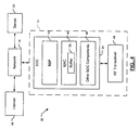
- FIG. 4 is a functional block diagram of an AP for a console in a wireless gaming network that includes an SOC and a radio frequency (RF) transceiver according to the present invention
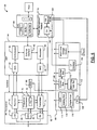
- FIG. 5 is a functional block diagram of a wireless network device according to the present invention.
- FIG. 6 is a timing diagram that illustrates client station TDM protocol delta times in a wireless LAN according to the prior art
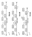
- FIG. 7A is a timing diagram that illustrates client station IFS times in a wireless LAN according to a first implementation of the present invention
- FIG. 7B is a timing diagram that illustrates client station IFS times in a wireless LAN according to a first implementation of the present invention
- FIG. 7C is a timing diagram that illustrates client station IFS times in a wireless LAN according to a first implementation of the present invention
- FIG. 7D is a timing diagram that illustrates client station IFS times in a wireless LAN according to a first implementation of the present invention
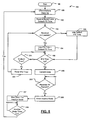
- FIG. 8 is a flowchart that illustrates steps performed by a wireless network device to select client station IFS times according to a first implementation of the present invention.
- FIG. 9A is a timing diagram that illustrates client station IFS times in a wireless LAN according to a second implementation of the present invention.
- FIG. 9B is a timing diagram that illustrates client station IFS times in a wireless LAN according to a second implementation of the present invention.
- FIG. 9C is a timing diagram that illustrates client station IFS times in a wireless LAN according to a second implementation of the present invention.
- FIG. 10 is a flowchart that illustrates steps performed by a wireless network device to select client station IFS times according to a second implementation of the present invention
- FIG. 11A is a timing diagram that illustrates client station IFS times in a wireless LAN according to a third implementation of the present invention.
- FIG. 11B is a timing diagram that illustrates client station IFS times in a wireless LAN according to a third implementation of the present invention.
- FIG. 11C is a timing diagram that illustrates client station IFS times in a wireless LAN according to a third implementation of the present invention.
- FIG. 11D is a timing diagram that illustrates client station IFS times in a wireless LAN according to a third implementation of the present invention.
- FIG. 12 is a flowchart that illustrates steps performed by a wireless network device to select client station IFS times according to a third implementation of the present invention
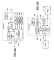
- FIG. 13A is a functional block diagram of a high definition television
- FIG. 13B is a functional block diagram of a vehicle control system:
- FIG. 13C is a functional block diagram of a cellular phone.
- FIG. 13D is a functional block diagram of a set top box.
- module and/or device refers to an application specific integrated circuit (ASIC), an electronic circuit, a processor (shared, dedicated, or group) and memory that execute one or more software or firmware programs, a combinational logic circuit, and/or other suitable components that provide the described functionality.
- ASIC application specific integrated circuit
- processor shared, dedicated, or group
- memory that execute one or more software or firmware programs, a combinational logic circuit, and/or other suitable components that provide the described functionality.
- An inter-frame space (IFS) time is a minimum time that a station waits after the communication medium becomes free prior to transmitting data.
- IFS inter-frame space
- the wireless protocol according to the present invention allows stations to use shorter and/or constant IFS times with no random backoff periods. By preventing collisions while eliminating the need for random backoff periods and by maintaining short IFS times for every station, the average awake time and the power consumption of all of the stations is reduced.
- a wireless network operating in either an infrastructure mode or an ad hoc mode may implement the wireless protocol as described herein.
- most or all of the stations need to transmit data regularly, for example, at each beacon interval.
- This type of network is a wireless console gaming application. Since most or all of the stations transmit frames to one or more other stations during each beacon interval, a master station determines a station access sequence after each beacon transmission. The master station can vary the station access sequence by randomizing or rotating the order following each beacon transmission. The IFS time for each station is dependent partly upon the access sequence and partly upon frames previously received in a particular beacon period. In this manner, a given client station will transmit data according to a first IFS time during a first beacon interval, and according to a second or different IFS time during a second beacon interval.
- all client stations transmit frames to every other client station during each beacon interval.
- the IFS times of each client station dictate a client access sequence for a given beacon interval.
- the client station access sequence is varied by randomizing or rotating the IFS times among the client stations following each beacon transmission. In this manner, a given client station will transmit data according to a first IFS time during a first beacon interval, and according to a second IFS time during a second beacon interval.
- a wireless gaming network 30 includes a host gaming device 32 and one or more client gaming devices 34.
- the client gaming devices 34 include wireless local area network (WLAN) hardware and operate as client stations in an infrastructure mode network.
- the host gaming device 32 also includes wireless LAN hardware and operates as an access point (AP) in the wireless gaming network.
- the wireless gaming network allows for greater mobility of the client gaming devices 34 and conserves operating power by reducing the overall duration of the active mode.
- the host gaming device 32 and the client gaming devices 34 may be a game console and wireless input devices, respectively, or any other suitable implementation of an AP and one or more wireless client stations.
- the wireless gaming network 30 excludes the host gaming device 32 and operates in an ad hoc mode.
- an exemplary AP 14 for a host gaming device 32 includes a system on chip (SOC) 34.
- the SOC 34 includes a baseband processor (BBP) 42, a media access control (MAC) device 44, and other SOC components, identified collectively at 46, including interfaces, memory, and/or processors.
- a radio frequency (RF) transceiver 48 along with the BBP 42 communicates with the MAC device 44.
- the RF transceiver 48 transmits/receives data to/from client stations in the wireless LAN. Since the AP 14 may have data that is intended for the client stations during the low power mode, the MAC device 44 includes a buffer 50.
- the MAC device 44 stores data that is intended for the client stations in the buffer 50 until the client stations enter the active mode.
- the AP 14 may be a node in a network 18 that includes other nodes such as a server 20 and may be connected to a distributed communications system 22 such as the Internet.
- Each client gaming device 34 includes an exemplary wireless network device 60 as shown in Figure 5 .
- the wireless network device 60 according to some implementations of the present invention is shown to include an RF transceiver module 62, a baseband processor module 64, a power and clock module 66, a MAC module 68, and a power management module 70.
- the RF transceiver 62 includes a receiver 72 and a transmitter 74. While not shown, the network device 60 can also include a processor and other standard components.
- a frequency synthesizer 76 includes a phase locked loop (PLL) 78 that receives a first reference frequency from an oscillator such as a crystal oscillator 80.
- the frequency synthesizer 76 also contains a voltage controlled oscillator (VCO) 82, which provides an adjustable frequency output based on an input signal thereto.
- VCO voltage controlled oscillator
- the frequency synthesizer 76 generates RF and IF output signals for the receiver and transmitter 72 and 74, respectively.
- a low noise amplifier (LNA) 84 receives signals from an antenna (not shown), amplifies the signals and outputs them to the receiver 72.
- LNA low noise amplifier
- PA power amplifier
- the BBP 64 includes an analog to digital converter (ADC) 88 that receives signals from the receiver 72.
- the ADC 88 communicates with a demodulator 90, which demodulates the signals.
- An output of the demodulator 90 communicates with an external interface 92, which communicates with the MAC 68.
- the MAC 68 sends signals to the external interface 92, which are modulated by a modulator 94 and output to a digital to analog converter (DAC) 96.
- the DAC 96 outputs signals to the transmitter 74.
- the BBP 64 also may include a PLL (not shown).
- the ADC 88 and the DAC 96 may be located on the RF transceiver 62.
- the power and clock module 66 includes a multi-level voltage source 98 that receives an input voltage such as VDD and a mode signal and outputs two or more voltage levels.
- the power and clock module 66 also includes a low power (LP) oscillator 100.
- the power management module 70 along with the MAC module 68 and processor (not shown) selects an operating mode of the wireless network device 60.
- the operating modes include active and inactive (i.e. low power) modes, although additional modes may be provided.
- the power management module 70 may also be located in the MAC module 68 or the power and clock module 66.
- An optional calibration module 102 that is associated with the power management module 70 is optionally used to calibrate the duration of the inactive mode.
- the calibration module 102 receives an output of the LP oscillator 100 and a PLL 104 and calibrates a value of a counter 106 that is used to calculate the duration of the inactive mode.
- the calibration can be performed periodically, on an event basis, randomly, before transitioning to the inactive mode and/or on any other suitable basis.
- the calibration module 102 may be omitted from the wireless network device 60.
- the power and clock module 66 further includes current and voltage bias circuits 108 and 110, respectively, that provide current and/or voltage biases to various circuits and/or modules (connections not shown) in the wireless network device 60.
- the current bias circuit 108 may include one or more off-chip calibration resistors (not shown) and the voltage bias circuit may include one or more on-chip resistors (not shown).
- a band gap voltage reference 112 may be used to bias the current bias circuit 108.
- a clock data recovery (CDR) module 114 performs clock recovery and includes analog and digital modules 116 and 118, respectively, or only digital modules.
- An output of the phase lock loop (PLL) 104 is coupled to the CDR module 114.
- One or more client stations enter the active mode prior to the transmission of a beacon signal 122.
- the AP transmits the beacon signal 122.
- the client stations In the ad hoc mode, however, one of the client stations transmits the beacon signal.
- the client stations attempt to transmit data according to assigned delay times following the reception of the beacon and during an awake interval 124 that is defined by the beacon signal 122.
- Delay, or delta, times for each client station can be varied each beacon interval.
- the default delay times may be carried in the beacon signal 122.
- the station access sequence for the client stations varies with each beacon interval.
- the client stations wait the delay time after the transmission medium becomes free before transmitting data.
- the device that receives the data packet may transmit an acknowledgment data packet if the destination of the packet is a single receiver.
- a first client station waits a first delta time 1 as illustrated at 126.
- Second, third, and nth client stations begin waiting second, third,..., and nth delta times, respectively. Since the delta time 1 is the shortest, it terminates first.
- the first client station transmits a data packet as illustrated at 128. While the first client station transmits a data packet at 128, the remaining client stations are still waiting for their corresponding delta times. In other words, the transmission of the first client station at 128 occurs while the remaining client stations are still waiting for their respective delta times to expire. Therefore, the second client station waits the second delta time 2 (the next shortest delta time) as illustrated at 130. The second client station then transmits a data packet as illustrated at 132.
- the third client station waits the third delta time 3 as illustrated at 134, and then transmits a data packet as illustrated at 136.
- the nth client station waits the nth delta time n as illustrated at 138, and then transmits a data packet as illustrated at 139.
- the delta times of each station can be varied.
- the nth client station may operate according to the first delta time 1
- the first client station may operate according to the third delta time 3.
- the delta times of the remaining client stations are varied.
- the delta times, and therefore the station access sequence may be varied sequentially, randomly, or in any other suitable manner.
- the client stations transition to the low power mode after all client stations complete transmission as illustrated by the termination of the awake interval 124. For example, in a wireless gaming network operating in the infrastructure or ad hoc mode, each client station remains awake in order to receive all data packets from other client stations in the network.
- each client station transitions to the low power mode immediately after transmitting a data packet.
- wireless input devices operating as client stations may transition to the low power mode immediately after transmitting data to the console (AP). Since the station access sequence varies following each beacon interval, the first, second, third, and nth client stations consume approximately the same average power over time.
- a timing diagram 140 illustrates a first implementation of the present invention.
- Each client station is assigned a default unique IFS time 1, 2, 3,..., n as opposed to the unique delta times described with respect to Figure 6 .
- the unique IFS times cause the stations to transmit in the order of ascending IFS, similar to the effect of the delta times described in FIG. 6 .
- the IFS times measure a time since the transmission media becomes free rather than a fixed time since the beacon transmission 122. In this manner, each client station waits a unique IFS time after the beacon transmission 122 and/or after a previous client station completes transmission.
- the client stations follow one or more rules during each beacon interval to determine whether to wait the assigned default IFS time or a shorter alternative IFS time. In one implementation, if a client station receives an expected number of data packets of a particular type (i.e. all preceding client stations have transmitted), then that client station waits the alternative IFS time.
- each client station has a single data packet to transmit to all other client stations.
- a client station may have more than one data packet type to transmit during a beacon interval. For example, a client gaming device may transmit a control data packet to a host gaming device, and then transmit a gaming data packet to all other client gaming devices. Therefore, subsequent client gaming devices would expect to receive the gaming data packet, but not the control data packet.
- the client station waits the IFS time 1.
- the IFS time 1 is the default IFS time of the first client station as illustrated at 142.
- the first client station waits the first IFS time 1 and transmits a data packet as illustrated at 144.
- the second client station is second in the station access sequence according to the IFS time 2, and therefore only expects to receive the data packet from the first client station (i.e. one data packet of an expected type) prior to transmitting. If the second client station receives the data packet from the first client station, the second client station waits the IFS time 1 as illustrated at 146, and transmits a data packet as illustrated at 148.
- the third client station is third in the station access sequence, and therefore expects to receive two data packets prior to transmitting. If the third client station receives the data packets from the first and second client stations, the third client station waits the IFS time 1 as illustrated at 150 and transmits a data packet as illustrated at 152. The nth client station operates analogously and waits the IFS time 1 as illustrated at 154 before transmitting a data packet as illustrated at 156. In subsequent beacon intervals, the IFS times are varied as described above, but the clients stations continue to follow the one or more rules for alternative IFS times.
- the awake interval 124 is significantly reduced if most or all client stations transmit and receive properly.
- the timing diagram 140 illustrates operation of the client stations when one client station does not receive a data packet from a preceding client station.
- the first client station transmits a data packet after IFS time 1 as illustrated at 158.
- the second client station does not properly receive the data packet from the first client station.
- the second client station may not receive the data packet due to noise or other network problems. Therefore, the second client station waits the IFS time 2 as illustrated at 160 prior to transmitting a data packet as illustrated at 162.
- the third and nth client stations properly receive all preceding data packets and wait the IFS time 1 prior to transmitting as illustrated at 164 and 166, respectively.
- the timing diagram 140 illustrates operation of the client stations when client stations 3 and above do not receive a data packet from a preceding client station.
- the first client station transmits a data packet after the IFS time 1 as illustrated at 170.
- the second client station receives the data packet and transmits after the IFS time 1 as illustrated at 172.
- the third and nth client stations do not receive the data packet from the second client station. For example, noise may corrupt the transmission from the second client station. Therefore, the third and nth client stations are not able to use IFS time 1, and use the default IFS times 3, and n, respectively.
- the second client station may be absent from the network and/or fail to transmit altogether as shown in Figure 7D .
- the first client station transmits a data packet after the IFS time 1 as illustrated at 174.
- the second client station does not transmit a data packet. Therefore, the third client station waits the default IFS time 3 after the first client station completes transmission as illustrated at 176.
- the third client station transmits a data packet after the IFS time 3 as illustrated at 178.
- the nth client station waits the default IFS time n after an (n-1)th client station completes transmission as illustrated at 180, and then transmits a data packet as illustrated at 182.
- a first IFS time selection method 184 begins in step 186.
- the client stations enter the active mode prior to receiving a beacon transmission.
- the client stations receive the beacon signal.
- the beacon signal includes data that determines the default IFS times of the client stations.
- the beacon signal may also indicate a slot m within the station access sequence for each client station.
- the beacon signal may include a single value that indicates both the default IFS time and the slot m of each client station.
- the beacon signal may include a timer synchronization function (TSF) value that indicates the default IFS time and/or the slot m of the client station.
- TSF timer synchronization function
- a client station determines whether it received m-1 data packets of the correct type. If true, the method 184 continues to step 194. If false, the method 184 continues to step 196. In step 194, the client station waits an alternative IFS time that is less than or equal to the default IFS time. In step 196, the client station waits the default IFS time.
- step 198 the client station determines whether the IFS time of step 194 or step 196 is up. If true, the method 184 continues to step 200. If false, the method 184 continues to step 201. In step 201, the client station determines whether the transmission medium is free. If true, the method 184 returns to step 198. If false, the method 184 continues to step 202. In step 202, the client station resets the IFS timer, and the method 184 returns to step 192. In other words, the client station continues to wait the IFS time for as long as the transmission medium is free. If the client station detects activity on the transmission medium, the IFS timer resets.
- step 200 the client station transmits a data packet.
- step 203 the method 184 determines whether the client station has received data packets from all the other client stations in the wireless network, and/or whether the beacon interval will expire soon. If true, the method 184 continues to step 206. If false, the method 184 returns to step 203 until all packets are received. In other words, if all stations have completed transmission and/or the beacon interval is to expire soon, the method 184 continues to step 206. Otherwise, the method 184 returns to step 203 and the station waits while each client station attempts to transmit in this manner.
- step 206 the client station enters the inactive mode.
- step 207 the method 184 starts an inactive mode timer.
- step 208 the method 184 determines whether the inactive mode timer is up. If true, the method 184 repeats for subsequent beacon intervals and returns to step 188. If false, the method 184 returns to step 208.
- the timing diagram 210 illustrates a second implementation of the present invention. If a client station receives a data packet of a particular type from the immediately preceding client station, the client station waits an alternative IFS time before transmitting data. If the client station does not receive the particular data packet from the immediately preceding client station, the client station waits the default IFS time before transmitting data.
- each client station in the network maintains a table of MAC addresses for all other client stations in the network. In other words, each client station is able to identify the data packet received from an immediately preceding client station based on its MAC address. Additionally, each data packet includes information that identifies its order in the station access sequence. In this manner, a receiving client station is able to determine if a particular data packet was transmitted by the immediately preceding client station.
- the client station waits the IFS time 1. If all client stations receive the data packet from the corresponding immediately preceding client station, all client stations wait the IFS time 1 as shown previously in Figure 7A .
- the timing diagram 210 illustrates operation of the client stations when one client station does not receive a data packet from an immediately preceding client station.
- the first client station transmits a data packet after IFS time 1 as illustrated at 212.
- the second client station does not properly receive the data packet from the first client station. Therefore, the second client station waits the IFS time 2 prior to transmitting a data packet as illustrated at 214.
- the third client station properly receives the data packet from the second client station, and the nth client station properly receives the data packet from an (n-1)th station. Therefore, the third client station and the nth client station wait the IFS time 1 before transmitting data.
- the timing diagram 210 illustrates operation of the client stations when all subsequent client stations do not receive a data packet from a preceding client station.
- the first client station transmits a data packet after IFS time 1 as illustrated at 216.
- the second, third, and nth client stations do not receive the data packet from the first client station.
- the second client station waits the IFS time 2 prior to transmitting a data packet as illustrated at 218.
- the third and nth client stations do not need to receive the data packet from the first client station in order to use the IFS time 1. If the third client station properly receives the data packet from the second client station, the third client station uses IFS time 1. Likewise, if the nth client station receives the data packet from the (n-1)th client station, the nth client station uses IFS time 1.
- the timing diagram 210 illustrates operation of the client stations when one client station stops transmitting or disconnects from the wireless network.
- the first client station transmits a data packet after IFS time 1 as illustrated at 220.
- the second client station does not transmit. Therefore, the third client station transmits a data packet after waiting the IFS time 3 as illustrated at 222. If the nth client station properly receives the data packet from the (n-1)th client station, the nth client station uses IFS time 1.
- subsequent client stations will use the alternative IFS time if the immediately preceding client station transmitted a particular data packet.
- collision may occur.
- the second client station will transmit a data packet after IFS time 2.
- the third client station will attempt to transmit a data packet after IFS time 1.
- the first client station will wait until the second client station completes transmission, and also attempt to transmit a data packet after IFS time 1, resulting in collision. Therefore, although the implementation described in Figures 9A through 9C provides significant improvement in a noise-free environment, it can be seen that operation in certain environments is undesirable.
- a second IFS time selection method 224 begins in step 226.
- the client stations transition to the active mode prior to receiving a beacon transmission.
- the client stations receive the beacon signal.
- the beacon signal includes data that determines the default IFS times of the client stations, which determines the slot in the station access sequence for each client station.
- a client station determines whether it received a data packet from the client station in slot m-1. If true, the method 224 continues to step 234. If false, the method 224 continues to step 236.
- the client station waits an alternative IFS time that is shorter than the default IFS time.
- the client station waits the default IFS time.
- step 2308 the client station determines whether the IFS time of step 234 or step 236 is up. If true, the method 224 continues to step 240. If false, the method 224 continues to step 241. In step 241, the client station determines whether the transmission medium is free. If true, the method 224 returns to step 238. If false, the method 224 continues to step 242. In step 242, the client station resets the IFS timer, and the method 224 returns to step 232.
- step 240 the client station transmits a data packet.
- step 243 the method 224 determines whether the client station has received data packets from all other client stations in the wireless network, and/or whether the beacon interval will expire soon. If true, the method 224 continues to step 246. If false, the method 224 returns to step 243 until all packets are received. In other words, if all stations have completed transmission and/or the beacon interval is to expire soon, the method 224 continues to step 246. Otherwise, the method 224 returns to step 243 and the station waits while each client attempts to transmit in this manner.
- step 246 the client station enters the inactive mode.
- step 247 the method 224 starts an inactive mode timer.
- step 248 the method 224 determines if the inactive mode timer is up. If true, the method 224 repeats for subsequent beacon intervals and returns to step 228. If false, the method 224 returns to step 248.
- the timing diagram 250 illustrates a third implementation of the present invention.
- the client stations are divided into two or more groups, and each client station within a group is assigned a default IFS time.
- the default IFS time for a particular client station is equal to a group IFS time plus an incremental delta time to determine station access sequence.
- Each group is assigned an IFS group number that determines a group IFS time IFSG1, IFSG2, IFSG3,...,IFSGx.
- Each client station in a particular group is assigned an IFS station number that determines an incremental delta time ⁇ 1, ⁇ 2, ⁇ 3,..., ⁇ q. Therefore, each client station is associated with an IFS group number and an IFS station number.
- the client station uses the smallest IFS time of a corresponding client station from which the client station has properly received a data packet. In other words, if the client station is associated with IFS station 1, the client station uses the smallest IFS time of any preceding IFS station 1.
- first and second client stations are stations 1 and 2 of a first group and have default IFS times 1 and 2, respectively.
- the IFS time 1 is equivalent to a group IFS time IFSG1 plus an incremental delta time ⁇ 1
- the IFS time 2 is equivalent to the group IFS time IFSG1 plus an incremental delta time ⁇ 2.
- Third and fourth client stations are stations 1 and 2 of a second group and have default IFS times 3 and 4, respectively.
- the IFS time 3 is equivalent to a group IFS time IFSG2 plus the incremental delta time ⁇ 1
- the IFS time 4 is equivalent to the group IFS time IFSG2 plus the incremental delta time ⁇ 2.
- Fifth and sixth client stations are stations 1 and 2 of a third group and have default IFS times 5 and 6, respectively.
- the IFS time 5 is equivalent to a group IFS time IFSG3 plus the incremental delta time ⁇ 1
- the IFS time 6 is equivalent to the group IFS time IFSG3 plus the incremental delta time ⁇ 2.
- Each successive group IFS time is greater than the preceding group IFS time plus an incremental delta time ⁇ q.
- the group IFS time IFSG2 is greater than the group IFS time IFSG1 time plus an incremental delta time ⁇ q.
- the group IFS time IFSG3 is greater than the group IFS time IFSG2 plus the incremental delta time ⁇ q.
- the first client station transmits a data packet after the IFS time 1 as illustrated at 252.
- the IFS time 1 is equivalent to the group IFS time IFSG1 plus the incremental delta time ⁇ 1 as illustrated at 253.
- the first, third, and fifth client stations are all associated with IFS station number 1. Therefore, if the third client station receives the data packet from the first client station, the third client station reuses the IFS time 1 of the first client station as illustrated at 254. If the fifth client station receives the data packets from the first and third client stations, the fifth client station reuses either the IFS time 1 or the IFS time 3, whichever is smaller. In the present example, the fifth client station reuses the IFS time 1 as illustrated at 256.
- the second client station transmits a data packet after the IFS time 2 as illustrated at 258.
- the IFS time 2 is equivalent to the group IFS time IFSG1 plus the incremental delta time ⁇ 2 as illustrated at 259.
- the fourth client station receives the data packet from the second client station and reuses the IFS time 2 of the second client station as illustrated at 260.
- the sixth client station receives the data packets from the second and fourth client stations, and therefore reuses the IFS time 2 or the IFS time 4. In the present example, the sixth client station reuses the IFS time 2 as illustrated at 262.
- the timing diagram 250 illustrates the operation of the client stations in the event that a client station does not properly receive a data packet from a corresponding client station in a preceding group.
- the first client station transmits a data packet after the IFS time 1 as illustrated at 264.
- the third client station receives the data packet from the first client station and transmits a data packet after the IFS time 1 as illustrated at 266.
- the fifth client station receives the data packets from the first and third client stations and transmits a data packet after the IFS time 1 as illustrated at 268.
- the second client station transmits a data packet after the I FS time 2 as illustrated at 270.
- the fourth client station does not properly receive the data packet from the second client station.
- the fourth client station is not able to reuse the IFS time 2 of the second client station, and transmits a data packet after the IFS time 4 as illustrated at 272.
- the IFS time 4 is equivalent to the group IFS time IFSG2 plus the incremental delta time ⁇ 2 as illustrated at 273.
- the sixth client station receives the data packets from the second client station and the fourth client station.
- the sixth client station is able to reuse either the IFS time 2 or the IFS time 4, whichever is smaller. Therefore, the sixth client station reuses the IFS time 2 as illustrated at 274.
- the timing diagram 250 illustrates the operation of the client stations in the event that multiple client stations do not properly receive a data packet from a corresponding client station in a preceding group.
- the fourth, fifth, and sixth client stations do not properly receive the data packet from the third client station.
- the first and third client stations use the IFS time 1 as described above.
- the fifth client station does not properly receive the data packet from the third client station, and therefore waits IFS time 5.
- the second client station waits IFS time 2, which is shorter than IFS time 5. Therefore, the second client station preempts the fifth client station and transmits after IFS time 2 as illustrated at 276.
- the fourth and sixth client stations reuse the IFS time 2 of the second client station.
- the fifth client station transmits a data packet after IFS time 5 as illustrated at 278.
- the IFS time 5 is equivalent to the group IFS time IFSG3 plus the incremental delta time ⁇ 1 as illustrated at 279.
- the timing diagram 250 illustrates the operation of the client stations in the event that one or more client stations stop transmitting on the network.
- the second client station is no longer transmitting data packets.
- the first, third, and fifth client stations transmit data packets after the IFS time 1 as described in previous examples.
- the fourth client station does not receive a data packet from the second client station, and therefore transmits a data packet after the IFS time 4 as illustrated at 280.
- the sixth client station receives the data packet from the fourth client station, and is able to reuse the IFS time 4 of the fourth client station as illustrated at 282.
- a third IFS time selection method 290 begins in step 292.
- the client stations come awake prior to receiving a beacon transmission.
- the client stations receive the beacon signal.
- the beacon signal includes data that determines group and station identification numbers for each client station as described with reference to Figures 11A through 11C , as well as corresponding default IFS times according to the group IFS time plus the incremental delta time. Alternatively, the group and station identification numbers are pre-assigned.
- a client station determines whether it received data packets from one or more client stations with a corresponding station identification number in a preceding group and received a data packet from the client station with the corresponding station identification number in the immediately preceding group.
- step 300 the client station reuses the shortest IFS time of a preceding client station having the same station identification number from which the client station successfully received a data packet.
- step 302 the client station waits the default IFS time.
- step 304 the client station determines whether the IFS time of step 300 or step 302 is up. If true, the method 290 continues to step 306. If false, the method 290 continues to step 308. In step 308, the client station determines whether the transmission medium is free. If true, the method 290 returns to step 304. If false, the method 290 continues to step 310. In step 310, the client station resets the IFS timer, and the method 290 returns to step 298.
- step 306 the client station transmits a data packet.
- the method 290 determines whether the client station has received data packets from all other client stations in the wireless network, and/or whether the beacon interval will expire soon. If true, the method 290 continues to step 318. If false, the method 290 returns to step 312 until all packets are received. In other words, if all stations have completed transmission and/or the beacon interval is to expire soon, the method 290 continues to step 318. Otherwise, the method 290 returns to step 312 and each client station attempts to transmit in this manner.
- the client station enters the inactive mode.
- the method 290 starts an inactive mode timer.
- the method 290 determines whether the inactive mode timer is up. If true, the method 290 repeats for subsequent beacon intervals and returns to step 294. If false, the method 290 repeats step 322.
- a subsequent client station may automatically reuse the IFS time of the corresponding client station from the immediately preceding group.
- a subsequent client station may reuse the shortest IFS time of any preceding client station provided that the subsequent client station receives data packets from all preceding stations. However, if the subsequent station does not receives all data packets, the subsequent station is still able to reuse the IFS time of a corresponding client station.
- the present invention can be implemented in a high definition television (HDTV) 420.
- the present invention may implement and/or be implemented in a WLAN interface of the HDTV 420.
- the HDTV 420 receives HDTV input signals in either a wired or wireless format and generates HDTV output signals for a display 426.
- signal processing circuit and/or control circuit 422 and/or other circuits (not shown) of the HDTV 420 may process data, perform coding and/or encryption, perform calculations, format data and/or perform any other type of HDTV processing that may be required.
- the HDTV 420 includes a power supply 423.
- the HDTV 420 may communicate with mass data storage 427 that stores data in a nonvolatile manner such as optical and/or magnetic storage devices.
- the HDTV 420 may be connected to memory 428 such as RAM, ROM, low latency nonvolatile memory such as flash memory and/or other suitable electronic data storage.
- the HDTV 420 also may support connections with a WLAN via a WLAN network interface 429.
- the present invention may implement and/or be implemented in a WLAN interface of control system of a vehicle 430.
- the present invention implements a powertrain control system 432 that receives inputs from one or more sensors such as temperature sensors, pressure sensors, rotational sensors, airflow sensors and/or any other suitable sensors and/or that generates one or more output control signals such as engine operating parameters, transmission operating parameters, and/or other control signals.
- the vehicle 430 includes a power supply 433.
- the present invention may also be implemented in other control systems 440 of the vehicle 430.
- the control system 440 may likewise receive signals from input sensors 442 and/or output control signals to one or more output devices 444.
- the control system 440 may be part of an anti-lock braking system (ABS), a navigation system, a telematics system, a vehicle telematics system, a lane departure system, an adaptive cruise control system, a vehicle entertainment system such as a stereo, DVD, compact disc and the like. Still other implementations are contemplated.
- the powertrain control system 432 may communicate with mass data storage 446 that stores data in a nonvolatile manner.
- the mass data storage 446 may include optical and/or magnetic storage devices.
- the powertrain control system 432 may be connected to memory 447 such as RAM, ROM, low latency nonvolatile memory such as flash memory and/or other suitable electronic data storage.
- the powertrain control system 432 also may support connections with a WLAN via a WLAN network interface 448.
- the control system 440 may also include mass data storage, memory and/or a WLAN interface (all not shown).
- the present invention can be implemented in a cellular phone 450 that may include a cellular antenna 451.
- the present invention may implement and/or be implemented in a WLAN interface of the cellular phone 450.
- the cellular phone 450 includes a microphone 456, an audio output 458 such as a speaker and/or audio output jack, a display 460 and/or an input device 462 such as a keypad, pointing device, voice actuation and/or other input device.
- Signal processing and/or control circuits 452 and/or other circuits (not shown) in the cellular phone 450 may process data, perform coding and/or encryption, perform calculations, format data and/or perform other cellular phone functions.
- the cellular phone includes a power supply 453.
- the cellular phone 450 may communicate with mass data storage 464 that stores data in a nonvolatile manner such as optical and/or magnetic storage devices.
- the cellular phone 450 may be connected to memory 466 such as RAM, ROM, low latency nonvolatile memory such as flash memory and/or other suitable electronic data storage.
- the cellular phone 450 also may support connections with a WLAN via a WLAN network interface 468.
- the present invention can be implemented in a set top box 480.
- the present invention may implement and/or be implemented in a WLAN interface of the set top box 480.
- the set top box 480 receives signals from a source such as a broadband source and outputs standard and/or high definition audio/video signals suitable for a display 488 such as a television and/or monitor and/or other video and/or audio output devices.
- Signal processing and/or control circuits 484 and/or other circuits (not shown) of the set top box 480 may process data, perform coding and/or encryption, perform calculations, format data and/or perform any other set top box function.
- the set top box 480 includes a power supply 483.
- the set top box 480 may communicate with mass data storage 490 that stores data in a nonvolatile manner.
- the mass data storage 490 may include optical and/or magnetic storage devices such as hard disk drives HDD and/or DVDs.
- the set top box 480 may be connected to memory 494 such as RAM, ROM, low latency nonvolatile memory such as flash memory and/or other suitable electronic data storage.
- the set top box 480 also may support connections with a WLAN via a WLAN network interface 496.
Abstract
Description
- The present invention relates to wireless networks, and more particularly to reducing power consumption of wireless network devices and improving network utilization.
- IEEE standards 802.11, 802.11a, 802.11b, 802.11g, 802.11h, 802.11n, 802.16, and 802.20, define several different standards for configuring wireless networks and devices. According to these standards, wireless network devices may be operated in either an infrastructure mode or an ad-hoc mode.
- In the infrastructure mode, the wireless network devices or client stations communicate with each other through an access point. In the ad-hoc mode, the wireless network devices communicate directly with each other and do not employ an access point. The term client station or mobile station may not necessarily mean that a wireless network device is actually mobile. For example, a desktop computer that is not mobile may incorporate a wireless network device and operate as a mobile station or client station.
- A wireless network that operates in the infrastructure mode includes an access point (AP) and at least one client station that communicates with the AP. For example, the wireless network may operate in an infrastructure mode. Since the client stations are often battery powered, it is important to minimize power consumption to preserve battery life. Therefore, some client stations implement a low power mode and an active, or "awake," mode. During the active mode, the client station transmits and/or receives data. During the low power mode, the client station shuts down components and/or alters operation to conserve power. Usually, the client station is not able to transmit or receive data during the lower power mode.
- Wireless network devices may be implemented by a system on chip (SOC) circuit that includes a baseband processor (BBP), a medium access controller (MAC) device, a host interface, and one or more processors. A host communicates with the wireless network device via the host interface. The SOC circuit may include a radio frequency (RF) transceiver or the RF transceiver may be located externally. The host interface may include a peripheral component interface (PCI) although other types of interfaces may be used.
- A power management device controls and selects different operating modes of the client stations. During operation, the power management device instructs some of the modules to transition to a low power mode to conserve power. Additional information may be found in
U.S. Patent Application Serial Nos. 10/650,887, filed on August 28, 2003 10/665,252, filed on September 19, 2003 11/070,481 filed on March 2, 2005 - Referring now to
Figure 1 , a firstwireless network 10 is illustrated in an infrastructure mode as defined by IEEE 802.11 and other future wireless standards. The firstwireless network 10 includes one ormore client stations 12 and one or more access points (AP) 14. Theclient station 12 and the AP 14 transmit and receivewireless signals 16. The AP 14 is a node in anetwork 18. Thenetwork 18 may be a local area network (LAN), a wide area network (WAN), or another network configuration. Thenetwork 18 may include other nodes such as aserver 20 and may be connected to adistributed communications system 22 such as the Internet. - The
client station 12 does not continuously transmit data to or receive data from the AP 14. Therefore, theclient station 12 implements a power savings mode when theclient station 12 and the AP 14 do not have data to exchange. Data commonly remains intact in a network for a predetermined amount of time before it is dropped. The incorporated IEEE standards provide the opportunity for theclient station 12 to inform the AP 14 when theclient station 12 is entering a low power mode (and will not be capable of receiving data for a predetermined period). After notifying the AP 14, theclient station 12 transitions to the low power mode. During the low power period, the AP 14 buffers data that is intended to be transmitted to theclient station 12. Following the low power period, theclient station 12 powers up and receives beacon transmissions from the AP 14. If the beacon transmissions indicate that the AP 14 has data for theclient station 12, or the host processor of theclient station 12 indicates it has data to transmit, theclient station 12 remains active. Otherwise, theclient station 12 enters the low power mode again. - The AP 14 attempts to transmit a beacon at a target beacon transmission time (TBTT). Before the AP 14 sends out a beacon transmission, the AP 14 determines whether other devices are currently transmitting data so that other devices are able to use the network. The
client station 12 transitions to the active mode prior to a beacon transmission to queue frames to transmit to theAP 14 in a buffer. Immediately following a beacon transmission, the AP 14 can exchange frames with one ormore client stations 12 in a deterministic order. For example, the AP 14 and theclients stations 12 may exchange data according to Time Division Multiplexed (TDM) protocol. The use of TDM protocol minimizes collisions that may occur when one or more of theclient stations 12 attempt to transmit data to the AP 14 simultaneously. However, other wireless networks that are located near the firstwireless network 10 may not operate according to the above-described TDM protocol. As such, collisions may occur between the other wireless networks and the firstwireless network 10. - In another implementation, each
client station 12 may wait for a random period prior to transmitting. This random period, or backoff period, reduces the likelihood that multiple client stations will attempt to transmit simultaneously. As such, a wireless network that implements the random backoff period has improved collision avoidance over a wireless network that implements a pure TOM scheme when multiple networks exist in an overlapping region. However, random backoff but does not guarantee collision avoidance. In certain applications, collision avoidance is critical. For example, wireless networks that exchange multicast data typically do not include a positive acknowledgement feature. In other words, a transmitting station does not receive acknowledgement from a receiving station that the data was correctly received. Further, as a result of the random backoff periods, the time required for all stations in the wireless network to complete a set of frame exchanges is increased. - Referring now to
Figure 2 , a secondwireless network 24 operates in an ad-hoc mode. The secondwireless network 24 includes multiple client stations 26-1, 26-2, and 26-3 that transmit and receivewireless signals 28. The client stations 26-1, 26-2, and 26-3 collectively form a LAN and communicate directly with each other. The client stations 26-1, 26-2, and 26-3 are not necessarily connected to another network. The client stations 26-1, 26-2, and 26-3 do not continuously transmit data to and receive data from each other. The client stations 26 implement a power savings mode when one of the client stations 26-1 does not have data to exchange with the other client stations 26-2 and 26-3. - The client stations 26-1, 26-2, and 26-3 are not required to buffer data as performed in the AP. For example, the client station 26-1 transmits the beacon to the other client stations 26-2 and 26-3. The client stations 26-2 and 26-3 transition to the active mode prior to the beacon transmission. During a beacon interval defined by the beacon transmission, each client station 26 transmits data in a deterministic order. For example, the client stations 26 may transmit data sequentially.
-
EP-A-1 233 574 discloses a wireless network device in a wireless network that includes a plurality of wireless network devices comprising an RF transceiver for transmitting and receiving data packets and for periodically transmitting and receiving a beacon. The system further comprises a control module that communicates with the RF transceiver for selecting one of a default IFS time and a second IFS time based on a data packet received for a second wireless network device. - A wireless network device comprises an RF transceiver that transmits and receives data packets and that periodically transmits or receives a beacon. A control module communicates with the RF transceiver, determines a default interframe space (IFS) time based on the beacon, and that selects one of the default IFS time and a second IFS time that is less than or equal to the default IFS time based on a number of data packets received after the beacon.
- In other features, the beacon includes data that is indicative of a transmission position m for the wireless network device. The control module selects the second IFS time when the RF transceiver receives m-1 data packets. The control module selects the default IFS time when the RF transceiver has received fewer than m-1 data packets.
- In still other features, the control module includes an IFS timer that is reset when data packets are received. The RF transceiver transmits a data packet after one of the default IFS time and the second IFS time. A power management module that transitions the wireless network device between an active mode and an inactive mode. The power management module transitions the wireless network device to the active mode prior to a scheduled beacon time. The power management module transitions the wireless network device to the inactive mode after the RF transceiver transmits a data packet. A wireless network comprising the wireless network device further comprises N-1 other wireless network devices. The power management module transitions the wireless network device to the inactive mode after all of the N wireless network devices transmit a data packet.
- In still other features, a wireless network comprises a plurality of the wireless network devices. The power management module transitions the wireless network devices to the inactive mode after an idle time on the network that is greater than a largest available IFS time. One of the wireless network devices is a coordinator that periodically transmits the beacon to the plurality of wireless network devices.
- In other features, a wireless network device comprises transmitting and receiving means for transmitting and receiving data packets and for periodically transmitting or receiving a beacon. The wireless network device comprises control means for communicating with the transmitting and receiving means, for determining a default interframe space (IFS) time based on the beacon, and for selecting one of the default IFS time and a second IFS time that is less than or equal to the default IFS time based on a number of data packets received after the beacon.
- In still other features, the beacon includes data that is indicative of a transmission position m for the wireless network device. The control means selects the second IFS time when the transmitting and receiving means receives m-1 data packets. The control means selects the default IFS time when the transmitting and receiving means has received fewer than m-1 data packets. The control means includes timing means for monitoring IFS times. The timing means is reset when data packets are received and the transmitting and receiving means transmits a data packet after one of the default IFS time and the second IFS time.
- In still other features, the wireless network device further comprises power management means for transitioning the wireless network device between an active mode and an inactive mode. The power management means transitions the wireless network device to the active mode prior to a scheduled beacon time. The power management means transitions the wireless network device to the inactive mode after the transmitting and receiving means transmits a data packet.
- In still other features, a wireless network comprising the wireless network device further comprises N-1 other wireless network devices. The power management means transitions the wireless network device to the inactive mode after all of the N wireless network devices transmit a data packet. The power management means transitions the wireless network devices to the inactive mode after an idle time on the network that is greater than a largest available IFS time. One of the wireless network devices is a coordinator that periodically transmits the beacon to the plurality of wireless network devices.
- In other features, a method for transmitting and receiving data with a wireless network device comprises at least one of transmitting and receiving data packets, at least one of periodically receiving and transmitting a beacon, determining a default interframe space (IFS) time based on the beacon, and selecting one of the default IFS time and a second IFS time that is less than or equal to the default IFS time based on a number of data packets received after the beacon.
- In still other features, the step of selecting includes selecting the second IFS time after receiving m-1 data packets. The step of selecting includes selecting the default IFS time when fewer than m-1 data packets are received. An IFS timer is reset when data packets are received and a data packet is transmitted after one of the default IFS time or the second IFS time.
- In other features, a computer program executed by a processor comprises at least one of transmitting and receiving data packets, at least one of periodically receiving and transmitting a beacon, determining a default interframe space (IFS) time based on the beacon, and selecting one of the default IFS time and a second IFS time that is less than or equal to the default IFS time based on a number of data packets received after the beacon.
- In still other features, the beacon includes data that is indicative of a transmission position m for a wireless network device. The step of selecting includes selecting the second IFS time after receiving m-1 data packets. The step of selecting includes selecting the default IFS time when fewer than m-1 data packets are received. An IFS timer is reset when data packets are received and a data packet is transmitted after one of the default IFS time or the second IFS time.
- In still other features, the wireless network device is transitioned between an active mode and an inactive mode. The step of transitioning includes transitioning the wireless network device to the active mode prior to a scheduled beacon time. The step of transitioning includes transitioning the wireless network device to the inactive mode after transmitting a data packet. The wireless network device is transitioned to the inactive mode after N wireless network devices transmit a data packet, wherein N is a number of wireless network devices in a wireless network including the wireless network device. The wireless network device is transitioned to the inactive mode after an idle time on a wireless network including the wireless network device that is greater than a largest available IFS time. The beacon is transmitted to a plurality of wireless network devices.
- In other features, a first wireless network device in a wireless network that includes a plurality of wireless network devices comprises an RF transceiver that transmits and receives data packets and that periodically transmits or receives a beacon. A control module communicates with the RF transceiver, determines a transmission position m and a default IFS time based on the beacon, selects a second IFS time when the RF transceiver receives a data packet from a second wireless network device having a transmission position m-1, and selects the default IFS time when the RF transceiver does not receive a data packet from the second wireless network device.
- In still other features, the second IFS time is less than or equal to the default IFS time. The RF transceiver transmits a data packet after one of the default IFS time or the second IFS time. A power management module transitions the wireless network device between an active mode and an inactive mode. The power management module transitions the wireless network device to the active mode prior to a scheduled beacon time. The power management module transitions the wireless network device to the inactive mode after the RF transceiver transmits the data packet.
- In still other features, a wireless network comprising the wireless network device further comprises N-1 wireless network devices. The power management module transitions the wireless network device to the inactive mode after all of the N wireless network devices transmit a data packet. A coordinator device periodically transmits the beacon to the RF transceiver. The transmission position m=2 and the second IFS time is equal to a default IFS time of the second wireless network device.
- In other features, a first wireless network device in a wireless network that includes a plurality of wireless network devices comprises transmitting and receiving means for transmitting and receiving data packets and for periodically transmitting or receiving a beacon, and control means for communicating with the transmitting and receiving means, for determining a transmission position m and a default IFS time based on the beacon, for selecting a second IFS time when the transmitting and receiving means receives a data packet from a second wireless network device having a transmission position m-1, and for selecting the default IFS time when the transmitting and receiving means does not receive a data packet from the second wireless network device.
- In still other features, the second IFS time is less than or equal to the default IFS time. The RF transceiver transmits a data packet after one of the default IFS time or the second IFS time. The wireless network device further comprises power management means for transitioning the wireless network device between an active mode and an inactive mode. The power management means transitions the wireless network device to the active mode prior to a scheduled beacon time. The power management means transitions the wireless network device to the inactive mode after the RF transceiver transmits the data packet.
- In still other features, a wireless network comprising the wireless network device of further comprises N-1 wireless network devices. The power management means transitions the wireless network device to the inactive mode after all of the N wireless network devices transmit a data packet. The transmission position m=2 and the second IFS time is equal to a default IFS time of the second wireless network device.
- In other features, a method for transmitting and receiving data with a first wireless network device in a wireless network that includes a plurality of wireless network devices comprises transmitting and receiving data packets, periodically transmitting or receiving a beacon, determining a transmission position m and a default IFS time based on the beacon, selecting a second IFS time when the first wireless network device receives a data packet from a second wireless network device having a transmission position m-1, and selecting the default IFS time when the first wireless network device does not receive a data packet from the second wireless network device.
- In still other features, the second IFS time is less than or equal to the default IFS time. A data packet is transmitted after one of the default IFS time or the second IFS time. The first wireless network device is transitioned between an active mode and an inactive mode. The step of transitioning includes transitioning the first wireless network device to the active mode prior to a scheduled beacon time. The step of transitioning includes transitioning the first wireless network device to the inactive mode after the first wireless network device transmits the data packet.
- In still other features, the wireless network includes N wireless network devices. The first wireless network device is transitioned to the inactive mode after all of the N wireless network devices transmit a data packet. The transmission position m=2 and the second IFS time is equal to a default IFS time of the second wireless network device.
- In other features, a computer program executed by a processor comprises transmitting and receiving data packets, periodically transmitting or receiving a beacon, determining a transmission position m and a default IFS time based on the beacon, selecting a second IFS time when a first wireless network device receives a data packet from a second wireless network device having a transmission position m-1, and selecting the default IFS time when the first wireless network device does not receive a data packet from the second wireless network device.
- In still other features, the second IFS time is less than or equal to the default IFS time. A data packet is transmitted after one of the default IFS time or the second IFS time. The first wireless network device is transitioned between an active mode and an inactive mode. The step of transitioning includes transitioning the first wireless network device to the active mode prior to a scheduled beacon time. The step of transitioning includes transitioning the first wireless network device to the inactive mode after the first wireless network device transmits the data packet. The transmission position m=2 and the second IFS time is equal to a default IFS time of the second wireless network device.
- In other features, a wireless network device in a wireless network that includes a plurality of wireless network devices comprises an RF transceiver that transmits and receives data packets and that periodically transmits or receives a beacon. A control module communicates with the RF transceiver, determines a group identifier and a station identifier based on the beacon, and selects one of a default IFS time and a second IFS time based on a data packet received.
- In still other features, the control module selects one of the default IFS time and the second IFS time based on the data packet received and at least one of the group identifier and/or the station identifier. The second IFS time is less than or equal to the default IFS time. The control module determines a group identifier x and a station identifier y based on the beacon. The control module selects the second IFS time when the data packet is received from a second wireless network device having a group identifier x-1 and a station identifier y. The control module selects the second IFS time when the data packet is received from a second wireless network device having a group identifier less than x and a station identifier y. The control module selects the default IFS time when the data packet is received from a second wireless network device having a group identifier x and a station identifier other than y.
- In still other features, a group IFS time is based on the group identifier, a delta IFS time is based on the station identifier, and the default IFS time is a sum of the group IFS time and the delta IFS time. The device transmits a data packet after one of the default IFS time or the second IFS time. A power management module that transitions the wireless network device between an active mode and an inactive mode. The power management module transitions the wireless network device to the active mode prior to a scheduled beacon time. The power management module transitions the wireless network device to the inactive mode after the RF transceiver transmits the data packet. A coordinator device periodically transmits the beacon to the RF transceiver.
- In other features, a wireless network device in a wireless network that includes a plurality of wireless network devices comprises transmitting and receiving means for transmitting and receiving data packets and for periodically transmitting or receiving a beacon and control means for communicating with the transmitting and receiving means, for determining a group identifier and a station identifier based on the beacon, and for selecting one of a default IFS time and a second IFS time based on a data packet received.
- In still other features, the control means selects one of the default IFS time and the second IFS time based on the data packet received and at least one of the group identifier and/or the station identifier. The second IFS time is less than or equal to the default IFS time. The control means determines a group identifier x and a station identifier y based on the beacon. The control means selects the second IFS time when the data packet is received from a second wireless network device having a group identifier x-1 and a station identifier y. The control means selects the second IFS time when the data packet is received from a second wireless network device having a group identifier less than x and a station identifier y. The control means selects the default IFS time when the data packet is received from a second wireless network device having a group identifier x and a station identifier other than y.
- In still other features, a group IFS time is based on the group identifier, a delta IFS time is based on the station identifier, and the default IFS time is a sum of the group IFS time and the delta IFS time. The device transmits a data packet after one of the default IFS time or the second IFS time. The wireless network device further comprises power management means for transitioning the wireless network device between an active mode and an inactive mode. The power management means transitions the wireless network device to the active mode prior to a scheduled beacon time. The power management means transitions the wireless network device to the inactive mode after the device transmits the data packet.
- In other features, a method for transmitting and receiving data with a first wireless network device in a wireless network that includes a plurality of wireless network devices comprises transmitting and receiving data packets, periodically transmitting or receiving a beacon, determining a group identifier and a station identifier based on the beacon, and selecting one of a default IFS time and a second IFS time based on a data packet received.
- In still other features, the step of selecting includes selecting one of the default IFS time and the second IFS time based on the data packet received and at least one of the group identifier and/or the station identifier. The second IFS time is less than or equal to the default IFS time. A group identifier x and a station identifier y are determined based on the beacon. The step of selecting includes selecting the second IFS time when the data packet is received from a second wireless network device having a group identifier x-1 and a station identifier y. The step of selecting includes selecting the second IFS time when the data packet is received from a second wireless network device having a group identifier less than x and a station identifier y. The step of selecting includes selecting the default IFS time when the data packet is received from a second wireless network device having a group identifier x and a station identifier other than y.
- In still other features, a group IFS time is based on the group identifier, a delta IFS time is based on the station identifier, and the default IFS time is a sum of the group IFS time and the delta IFS time. A data packet is transmitted after one of the default IFS time or the second IFS time. The first wireless network device is transitioned between an active mode and an inactive mode. The step of transitioning includes transitioning the first wireless network device to the active mode prior to a scheduled beacon time. The step of transitioning includes transitioning the wireless network device to the inactive mode after transmitting the data packet.
- In other features, a computer program executed by a processor comprises transmitting and receiving data packets, periodically transmitting or receiving a beacon, determining a group identifier and a station identifier based on the beacon, and selecting one of a default IFS time and a second IFS time based on a data packet received.
- In still other features, the step of selecting includes selecting one of the default IFS time and the second IFS time based on the data packet received and at least one of the group identifier and/or the station identifier. The second IFS time is less than or equal to the default IFS time. A group identifier x and a station identifier y are determined based on the beacon. The step of selecting includes selecting the second IFS time when the data packet is received from a wireless network device having a group identifier x-1 and a station identifier y.
- In still other features, the step of selecting includes selecting the second IFS time when the data packet is received from a wireless network device having a group identifier less than x and a station identifier y. The step of selecting includes selecting the default IFS time when the data packet is received from a wireless network device having a group identifier x and a station identifier other than y. A group IFS time is based on the group identifier, a delta IFS time is based on the station identifier, and the default IFS time is a sum of the group IFS time and the delta IFS time. A data packet is transmitted after one of the default IFS time or the second IFS time.
- In still other features, a wireless network device is transitioned between an active mode and an inactive mode. The step of transitioning includes transitioning the wireless network device to the active mode prior to a scheduled beacon time. The step of transitioning includes transitioning the wireless network device to the inactive mode after transmitting the data packet.
- In still other features, the systems and methods described above are implemented by a computer program executed by one or more processors. The computer program can reside on a computer readable medium such as but not limited to memory, non-volatile data storage and/or other suitable tangible storage mediums.
- Further areas of applicability of the present invention will become apparent from the detailed description provided hereinafter. It should be understood that the detailed description and specific examples, while indicating the preferred embodiment of the invention, are intended for purposes of illustration only and are not intended to limit the scope of the invention.
- The present invention will become more fully understood from the detailed description and the accompanying drawings, wherein:
-
FIG. 1 is a functional block diagram of a wireless network that is configured in an infrastructure mode and that includes one or more client stations and an access point (AP) according to the prior art; -
FIG. 2 is a functional block diagram of a wireless network that is configured in an ad-hoc mode and that includes multiple client stations according to the prior art; -
FIG. 3 is a functional block diagram of a wireless gaming network that is configured in an infrastructure mode wireless local area network (LAN) according to the present invention; -
FIG. 4 is a functional block diagram of an AP for a console in a wireless gaming network that includes an SOC and a radio frequency (RF) transceiver according to the present invention; -
FIG. 5 is a functional block diagram of a wireless network device according to the present invention; -
FIG. 6 is a timing diagram that illustrates client station TDM protocol delta times in a wireless LAN according to the prior art; -
FIG. 7A is a timing diagram that illustrates client station IFS times in a wireless LAN according to a first implementation of the present invention; -
FIG. 7B is a timing diagram that illustrates client station IFS times in a wireless LAN according to a first implementation of the present invention; -
FIG. 7C is a timing diagram that illustrates client station IFS times in a wireless LAN according to a first implementation of the present invention; -
FIG. 7D is a timing diagram that illustrates client station IFS times in a wireless LAN according to a first implementation of the present invention; -
FIG. 8 is a flowchart that illustrates steps performed by a wireless network device to select client station IFS times according to a first implementation of the present invention. -
FIG. 9A is a timing diagram that illustrates client station IFS times in a wireless LAN according to a second implementation of the present invention; -
FIG. 9B is a timing diagram that illustrates client station IFS times in a wireless LAN according to a second implementation of the present invention; -
FIG. 9C is a timing diagram that illustrates client station IFS times in a wireless LAN according to a second implementation of the present invention; -
FIG. 10 is a flowchart that illustrates steps performed by a wireless network device to select client station IFS times according to a second implementation of the present invention; -
FIG. 11A is a timing diagram that illustrates client station IFS times in a wireless LAN according to a third implementation of the present invention; -
FIG. 11B is a timing diagram that illustrates client station IFS times in a wireless LAN according to a third implementation of the present invention; -
FIG. 11C is a timing diagram that illustrates client station IFS times in a wireless LAN according to a third implementation of the present invention; -
FIG. 11D is a timing diagram that illustrates client station IFS times in a wireless LAN according to a third implementation of the present invention; -
FIG. 12 is a flowchart that illustrates steps performed by a wireless network device to select client station IFS times according to a third implementation of the present invention; -
FIG. 13A is a functional block diagram of a high definition television; -
FIG. 13B is a functional block diagram of a vehicle control system: -
FIG. 13C is a functional block diagram of a cellular phone; and -
FIG. 13D is a functional block diagram of a set top box. - The following description of the preferred embodiment(s) is merely exemplary in nature and is in no way intended to limit the invention, its application, or uses. For purposes of clarity, the same reference numbers will be used in the drawings to identify similar elements. As used herein, the term module and/or device refers to an application specific integrated circuit (ASIC), an electronic circuit, a processor (shared, dedicated, or group) and memory that execute one or more software or firmware programs, a combinational logic circuit, and/or other suitable components that provide the described functionality.
- An inter-frame space (IFS) time is a minimum time that a station waits after the communication medium becomes free prior to transmitting data. To minimize power consumption, the wireless protocol according to the present invention allows stations to use shorter and/or constant IFS times with no random backoff periods. By preventing collisions while eliminating the need for random backoff periods and by maintaining short IFS times for every station, the average awake time and the power consumption of all of the stations is reduced. A wireless network operating in either an infrastructure mode or an ad hoc mode may implement the wireless protocol as described herein.
- In some types of networks, most or all of the stations need to transmit data regularly, for example, at each beacon interval. One example of this type of network is a wireless console gaming application. Since most or all of the stations transmit frames to one or more other stations during each beacon interval, a master station determines a station access sequence after each beacon transmission. The master station can vary the station access sequence by randomizing or rotating the order following each beacon transmission. The IFS time for each station is dependent partly upon the access sequence and partly upon frames previously received in a particular beacon period. In this manner, a given client station will transmit data according to a first IFS time during a first beacon interval, and according to a second or different IFS time during a second beacon interval.
- In a wireless gaming network operating in the infrastructure or ad hoc mode, all client stations transmit frames to every other client station during each beacon interval. The IFS times of each client station dictate a client access sequence for a given beacon interval. The client station access sequence is varied by randomizing or rotating the IFS times among the client stations following each beacon transmission. In this manner, a given client station will transmit data according to a first IFS time during a first beacon interval, and according to a second IFS time during a second beacon interval.
- Referring now to
Figure 3 , awireless gaming network 30 includes ahost gaming device 32 and one or moreclient gaming devices 34. Theclient gaming devices 34 include wireless local area network (WLAN) hardware and operate as client stations in an infrastructure mode network. Thehost gaming device 32 also includes wireless LAN hardware and operates as an access point (AP) in the wireless gaming network. The wireless gaming network allows for greater mobility of theclient gaming devices 34 and conserves operating power by reducing the overall duration of the active mode. Those skilled in the art can appreciate that thehost gaming device 32 and theclient gaming devices 34 may be a game console and wireless input devices, respectively, or any other suitable implementation of an AP and one or more wireless client stations. Alternatively, thewireless gaming network 30 excludes thehost gaming device 32 and operates in an ad hoc mode. - Referring now to
Figure 4 , anexemplary AP 14 for ahost gaming device 32 includes a system on chip (SOC) 34. TheSOC 34 includes a baseband processor (BBP) 42, a media access control (MAC) device 44, and other SOC components, identified collectively at 46, including interfaces, memory, and/or processors. A radio frequency (RF)transceiver 48 along with the BBP 42 communicates with the MAC device 44. TheRF transceiver 48 transmits/receives data to/from client stations in the wireless LAN. Since theAP 14 may have data that is intended for the client stations during the low power mode, the MAC device 44 includes abuffer 50. The MAC device 44 stores data that is intended for the client stations in thebuffer 50 until the client stations enter the active mode. As illustrated inFigure 1 , theAP 14 may be a node in anetwork 18 that includes other nodes such as aserver 20 and may be connected to a distributedcommunications system 22 such as the Internet. - Each
client gaming device 34 includes an exemplarywireless network device 60 as shown inFigure 5 . Thewireless network device 60 according to some implementations of the present invention is shown to include anRF transceiver module 62, abaseband processor module 64, a power andclock module 66, aMAC module 68, and apower management module 70. TheRF transceiver 62 includes areceiver 72 and atransmitter 74. While not shown, thenetwork device 60 can also include a processor and other standard components. - A
frequency synthesizer 76 includes a phase locked loop (PLL) 78 that receives a first reference frequency from an oscillator such as acrystal oscillator 80. Thefrequency synthesizer 76 also contains a voltage controlled oscillator (VCO) 82, which provides an adjustable frequency output based on an input signal thereto. Thefrequency synthesizer 76 generates RF and IF output signals for the receiver andtransmitter - During receiver operation, an input of a low noise amplifier (LNA) 84 receives signals from an antenna (not shown), amplifies the signals and outputs them to the
receiver 72. During transmitter operation, an output of thetransmitter 74 is received by a power amplifier (PA) 86, which outputs amplified signals to the antenna. - On the receiver side, the
BBP 64 includes an analog to digital converter (ADC) 88 that receives signals from thereceiver 72. TheADC 88 communicates with ademodulator 90, which demodulates the signals. An output of thedemodulator 90 communicates with anexternal interface 92, which communicates with theMAC 68. On the transmitter side, theMAC 68 sends signals to theexternal interface 92, which are modulated by amodulator 94 and output to a digital to analog converter (DAC) 96. TheDAC 96 outputs signals to thetransmitter 74. TheBBP 64 also may include a PLL (not shown). Alternatively, theADC 88 and theDAC 96 may be located on theRF transceiver 62. - The power and
clock module 66 includes a multi-level voltage source 98 that receives an input voltage such as VDD and a mode signal and outputs two or more voltage levels. The power andclock module 66 also includes a low power (LP)oscillator 100. Thepower management module 70 along with theMAC module 68 and processor (not shown) selects an operating mode of thewireless network device 60. The operating modes include active and inactive (i.e. low power) modes, although additional modes may be provided. Thepower management module 70 may also be located in theMAC module 68 or the power andclock module 66. - An
optional calibration module 102 that is associated with thepower management module 70 is optionally used to calibrate the duration of the inactive mode. Thecalibration module 102 receives an output of theLP oscillator 100 and aPLL 104 and calibrates a value of acounter 106 that is used to calculate the duration of the inactive mode. The calibration can be performed periodically, on an event basis, randomly, before transitioning to the inactive mode and/or on any other suitable basis. Alternatively, thecalibration module 102 may be omitted from thewireless network device 60. - The power and
clock module 66 further includes current and voltage biascircuits wireless network device 60. Thecurrent bias circuit 108 may include one or more off-chip calibration resistors (not shown) and the voltage bias circuit may include one or more on-chip resistors (not shown). A bandgap voltage reference 112 may be used to bias thecurrent bias circuit 108. - A clock data recovery (CDR)
module 114 performs clock recovery and includes analog anddigital modules CDR module 114. - Referring to now
Figure 6 , an exemplary TDM timing diagram 120 according to the prior art is illustrated. One or more client stations enter the active mode prior to the transmission of abeacon signal 122. In a wireless network operating in the infrastructure mode, the AP transmits thebeacon signal 122. In the ad hoc mode, however, one of the client stations transmits the beacon signal. The client stations attempt to transmit data according to assigned delay times following the reception of the beacon and during anawake interval 124 that is defined by thebeacon signal 122. - Delay, or delta, times for each client station can be varied each beacon interval. For example, the default delay times may be carried in the
beacon signal 122. As a result, the station access sequence for the client stations varies with each beacon interval. The client stations wait the delay time after the transmission medium becomes free before transmitting data. When transmission of a data frame or packet over the medium is complete, the device that receives the data packet may transmit an acknowledgment data packet if the destination of the packet is a single receiver. - A first client station waits a
first delta time 1 as illustrated at 126. Second, third, and nth client stations begin waiting second, third,..., and nth delta times, respectively. Since thedelta time 1 is the shortest, it terminates first. The first client station transmits a data packet as illustrated at 128. While the first client station transmits a data packet at 128, the remaining client stations are still waiting for their corresponding delta times. In other words, the transmission of the first client station at 128 occurs while the remaining client stations are still waiting for their respective delta times to expire. Therefore, the second client station waits the second delta time 2 (the next shortest delta time) as illustrated at 130. The second client station then transmits a data packet as illustrated at 132. The third client station waits thethird delta time 3 as illustrated at 134, and then transmits a data packet as illustrated at 136. The nth client station waits the nth delta time n as illustrated at 138, and then transmits a data packet as illustrated at 139. - In subsequent beacon intervals (not shown), the delta times of each station can be varied. For example, the nth client station may operate according to the
first delta time 1, and the first client station may operate according to thethird delta time 3. Similarly, the delta times of the remaining client stations are varied. Those skilled in the art can appreciate that the delta times, and therefore the station access sequence, may be varied sequentially, randomly, or in any other suitable manner. - The client stations transition to the low power mode after all client stations complete transmission as illustrated by the termination of the
awake interval 124. For example, in a wireless gaming network operating in the infrastructure or ad hoc mode, each client station remains awake in order to receive all data packets from other client stations in the network. - Alternatively, each client station transitions to the low power mode immediately after transmitting a data packet. For example, in a wireless gaming console operating in the infrastructure mode, wireless input devices operating as client stations may transition to the low power mode immediately after transmitting data to the console (AP). Since the station access sequence varies following each beacon interval, the first, second, third, and nth client stations consume approximately the same average power over time.
- Referring now to
Figures 7A through 7D , a timing diagram 140 illustrates a first implementation of the present invention. Each client station is assigned a defaultunique IFS time Figure 6 . The unique IFS times cause the stations to transmit in the order of ascending IFS, similar to the effect of the delta times described inFIG. 6 . However, the IFS times measure a time since the transmission media becomes free rather than a fixed time since thebeacon transmission 122. In this manner, each client station waits a unique IFS time after thebeacon transmission 122 and/or after a previous client station completes transmission. - The client stations follow one or more rules during each beacon interval to determine whether to wait the assigned default IFS time or a shorter alternative IFS time. In one implementation, if a client station receives an expected number of data packets of a particular type (i.e. all preceding client stations have transmitted), then that client station waits the alternative IFS time. In typical wireless gaming applications, each client station has a single data packet to transmit to all other client stations. However, a client station may have more than one data packet type to transmit during a beacon interval. For example, a client gaming device may transmit a control data packet to a host gaming device, and then transmit a gaming data packet to all other client gaming devices. Therefore, subsequent client gaming devices would expect to receive the gaming data packet, but not the control data packet.
- Referring now to
Figure 7A , if a given client station receives data packets from all previously transmitting client stations, the client station waits theIFS time 1. TheIFS time 1 is the default IFS time of the first client station as illustrated at 142. The first client station waits thefirst IFS time 1 and transmits a data packet as illustrated at 144. The second client station is second in the station access sequence according to theIFS time 2, and therefore only expects to receive the data packet from the first client station (i.e. one data packet of an expected type) prior to transmitting. If the second client station receives the data packet from the first client station, the second client station waits theIFS time 1 as illustrated at 146, and transmits a data packet as illustrated at 148. - In other words, because the first client station already transmitted data during this beacon interval, there is no danger that collision will occur between the first client station and the second client station at
IFS time 1. The third client station is third in the station access sequence, and therefore expects to receive two data packets prior to transmitting. If the third client station receives the data packets from the first and second client stations, the third client station waits theIFS time 1 as illustrated at 150 and transmits a data packet as illustrated at 152. The nth client station operates analogously and waits theIFS time 1 as illustrated at 154 before transmitting a data packet as illustrated at 156. In subsequent beacon intervals, the IFS times are varied as described above, but the clients stations continue to follow the one or more rules for alternative IFS times. - In this manner, data is exchanged between all client stations more quickly, and the overall awake time of the client stations is reduced, minimizing power consumption. Additionally, since the percentage of time required for all stations to transmit their data is reduced, there is a greater likelihood that all stations will be able to transmit each beacon interval when competing for the medium with other WLAN networks. As described above and in
Figure 7A , theawake interval 124 is significantly reduced if most or all client stations transmit and receive properly. - Referring now to
Figure 7B , the timing diagram 140 illustrates operation of the client stations when one client station does not receive a data packet from a preceding client station. The first client station transmits a data packet afterIFS time 1 as illustrated at 158. However, the second client station does not properly receive the data packet from the first client station. For example, the second client station may not receive the data packet due to noise or other network problems. Therefore, the second client station waits theIFS time 2 as illustrated at 160 prior to transmitting a data packet as illustrated at 162. The third and nth client stations properly receive all preceding data packets and wait theIFS time 1 prior to transmitting as illustrated at 164 and 166, respectively. - Referring now to
Figure 7C , the timing diagram 140 illustrates operation of the client stations whenclient stations 3 and above do not receive a data packet from a preceding client station. The first client station transmits a data packet after theIFS time 1 as illustrated at 170. The second client station receives the data packet and transmits after theIFS time 1 as illustrated at 172. The third and nth client stations do not receive the data packet from the second client station. For example, noise may corrupt the transmission from the second client station. Therefore, the third and nth client stations are not able to useIFS time 1, and use thedefault IFS times 3, and n, respectively. - Alternatively, the second client station may be absent from the network and/or fail to transmit altogether as shown in
Figure 7D . The first client station transmits a data packet after theIFS time 1 as illustrated at 174. The second client station does not transmit a data packet. Therefore, the third client station waits thedefault IFS time 3 after the first client station completes transmission as illustrated at 176. The third client station transmits a data packet after theIFS time 3 as illustrated at 178. Similarly, the nth client station waits the default IFS time n after an (n-1)th client station completes transmission as illustrated at 180, and then transmits a data packet as illustrated at 182. - Referring now to
Figure 8 , a first IFStime selection method 184 begins instep 186. Instep 188, the client stations enter the active mode prior to receiving a beacon transmission. Instep 190, the client stations receive the beacon signal. The beacon signal includes data that determines the default IFS times of the client stations. In the present implementation, the beacon signal may also indicate a slot m within the station access sequence for each client station. Alternatively, the beacon signal may include a single value that indicates both the default IFS time and the slot m of each client station. For example, the beacon signal may include a timer synchronization function (TSF) value that indicates the default IFS time and/or the slot m of the client station. Instep 192, a client station determines whether it received m-1 data packets of the correct type. If true, themethod 184 continues to step 194. If false, themethod 184 continues to step 196. Instep 194, the client station waits an alternative IFS time that is less than or equal to the default IFS time. Instep 196, the client station waits the default IFS time. - In
step 198, the client station determines whether the IFS time ofstep 194 or step 196 is up. If true, themethod 184 continues to step 200. If false, themethod 184 continues to step 201. Instep 201, the client station determines whether the transmission medium is free. If true, themethod 184 returns to step 198. If false, themethod 184 continues to step 202. Instep 202, the client station resets the IFS timer, and themethod 184 returns to step 192. In other words, the client station continues to wait the IFS time for as long as the transmission medium is free. If the client station detects activity on the transmission medium, the IFS timer resets. - In
step 200, the client station transmits a data packet. Instep 203, themethod 184 determines whether the client station has received data packets from all the other client stations in the wireless network, and/or whether the beacon interval will expire soon. If true, themethod 184 continues to step 206. If false, themethod 184 returns to step 203 until all packets are received. In other words, if all stations have completed transmission and/or the beacon interval is to expire soon, themethod 184 continues to step 206. Otherwise, themethod 184 returns to step 203 and the station waits while each client station attempts to transmit in this manner. Instep 206, the client station enters the inactive mode. Instep 207, themethod 184 starts an inactive mode timer. Instep 208, themethod 184 determines whether the inactive mode timer is up. If true, themethod 184 repeats for subsequent beacon intervals and returns to step 188. If false, themethod 184 returns to step 208. - Referring now to
Figures 9A through 9C , the timing diagram 210 illustrates a second implementation of the present invention. If a client station receives a data packet of a particular type from the immediately preceding client station, the client station waits an alternative IFS time before transmitting data. If the client station does not receive the particular data packet from the immediately preceding client station, the client station waits the default IFS time before transmitting data. In the present implementation, each client station in the network maintains a table of MAC addresses for all other client stations in the network. In other words, each client station is able to identify the data packet received from an immediately preceding client station based on its MAC address. Additionally, each data packet includes information that identifies its order in the station access sequence. In this manner, a receiving client station is able to determine if a particular data packet was transmitted by the immediately preceding client station. - If a given client station receives the data packet from the immediately preceding client station, the client station waits the
IFS time 1. If all client stations receive the data packet from the corresponding immediately preceding client station, all client stations wait theIFS time 1 as shown previously inFigure 7A . Referring now toFigure 9A , the timing diagram 210 illustrates operation of the client stations when one client station does not receive a data packet from an immediately preceding client station. The first client station transmits a data packet afterIFS time 1 as illustrated at 212. However, the second client station does not properly receive the data packet from the first client station. Therefore, the second client station waits theIFS time 2 prior to transmitting a data packet as illustrated at 214. The third client station properly receives the data packet from the second client station, and the nth client station properly receives the data packet from an (n-1)th station. Therefore, the third client station and the nth client station wait theIFS time 1 before transmitting data. - Referring now to
Figure 9B , the timing diagram 210 illustrates operation of the client stations when all subsequent client stations do not receive a data packet from a preceding client station. The first client station transmits a data packet afterIFS time 1 as illustrated at 216. The second, third, and nth client stations do not receive the data packet from the first client station. The second client station waits theIFS time 2 prior to transmitting a data packet as illustrated at 218. However, according to the present implementation, the third and nth client stations do not need to receive the data packet from the first client station in order to use theIFS time 1. If the third client station properly receives the data packet from the second client station, the third client station usesIFS time 1. Likewise, if the nth client station receives the data packet from the (n-1)th client station, the nth client station usesIFS time 1. - Referring now to
Figure 9C , the timing diagram 210 illustrates operation of the client stations when one client station stops transmitting or disconnects from the wireless network. The first client station transmits a data packet afterIFS time 1 as illustrated at 220. The second client station does not transmit. Therefore, the third client station transmits a data packet after waiting theIFS time 3 as illustrated at 222. If the nth client station properly receives the data packet from the (n-1)th client station, the nth client station usesIFS time 1. - As described above in
Figures 9A through 9C , subsequent client stations will use the alternative IFS time if the immediately preceding client station transmitted a particular data packet. However, in certain situations, collision may occur. For example, if the first client station is not able to transmit a data packet, the second client station will transmit a data packet afterIFS time 2. After the second client station transmits the data packet, the third client station will attempt to transmit a data packet afterIFS time 1. However, the first client station will wait until the second client station completes transmission, and also attempt to transmit a data packet afterIFS time 1, resulting in collision. Therefore, although the implementation described inFigures 9A through 9C provides significant improvement in a noise-free environment, it can be seen that operation in certain environments is undesirable. - Referring now to
Figure 10 , a second IFStime selection method 224 begins instep 226. Instep 228, the client stations transition to the active mode prior to receiving a beacon transmission. Instep 230, the client stations receive the beacon signal. The beacon signal includes data that determines the default IFS times of the client stations, which determines the slot in the station access sequence for each client station. Instep 232, a client station determines whether it received a data packet from the client station in slot m-1. If true, themethod 224 continues to step 234. If false, themethod 224 continues to step 236. Instep 234, the client station waits an alternative IFS time that is shorter than the default IFS time. Instep 236, the client station waits the default IFS time. - In
step 238, the client station determines whether the IFS time ofstep 234 or step 236 is up. If true, themethod 224 continues to step 240. If false, themethod 224 continues to step 241. Instep 241, the client station determines whether the transmission medium is free. If true, themethod 224 returns to step 238. If false, themethod 224 continues to step 242. Instep 242, the client station resets the IFS timer, and themethod 224 returns to step 232. - In
step 240, the client station transmits a data packet. Instep 243, themethod 224 determines whether the client station has received data packets from all other client stations in the wireless network, and/or whether the beacon interval will expire soon. If true, themethod 224 continues to step 246. If false, themethod 224 returns to step 243 until all packets are received. In other words, if all stations have completed transmission and/or the beacon interval is to expire soon, themethod 224 continues to step 246. Otherwise, themethod 224 returns to step 243 and the station waits while each client attempts to transmit in this manner. Instep 246, the client station enters the inactive mode. Instep 247, themethod 224 starts an inactive mode timer. Instep 248, themethod 224 determines if the inactive mode timer is up. If true, themethod 224 repeats for subsequent beacon intervals and returns to step 228. If false, themethod 224 returns to step 248. - Referring now to
Figures 11A through 11D , the timing diagram 250 illustrates a third implementation of the present invention. The client stations are divided into two or more groups, and each client station within a group is assigned a default IFS time. In one implementation, the default IFS time for a particular client station is equal to a group IFS time plus an incremental delta time to determine station access sequence. Each group is assigned an IFS group number that determines a group IFS time IFSG1, IFSG2, IFSG3,...,IFSGx. Each client station in a particular group is assigned an IFS station number that determines an incremental delta time Δ1, Δ2, Δ3,...,Δq. Therefore, each client station is associated with an IFS group number and an IFS station number. - If a client station properly receives a data packet from a corresponding client station of an immediately preceding group, the client station uses the smallest IFS time of a corresponding client station from which the client station has properly received a data packet. In other words, if the client station is associated with
IFS station 1, the client station uses the smallest IFS time of any precedingIFS station 1. - Referring to
Figure 11A , first and second client stations arestations default IFS times IFS time 1 is equivalent to a group IFS time IFSG1 plus an incremental delta time Δ1, and theIFS time 2 is equivalent to the group IFS time IFSG1 plus an incremental delta time Δ2. Third and fourth client stations arestations default IFS times IFS time 3 is equivalent to a group IFS time IFSG2 plus the incremental delta time Δ1, and theIFS time 4 is equivalent to the group IFS time IFSG2 plus the incremental delta time Δ2. Fifth and sixth client stations arestations default IFS times IFS time 5 is equivalent to a group IFS time IFSG3 plus the incremental delta time Δ1, and theIFS time 6 is equivalent to the group IFS time IFSG3 plus the incremental delta time Δ2. - Each successive group IFS time is greater than the preceding group IFS time plus an incremental delta time Δq. For example, the group IFS time IFSG2 is greater than the group IFS time IFSG1 time plus an incremental delta time Δq. Similarly, the group IFS time IFSG3 is greater than the group IFS time IFSG2 plus the incremental delta time Δq. In this manner, the client stations in subsequent groups have longer default IFS times than the client stations of preceding groups. Therefore, collisions between client stations of different groups is avoided.
- The first client station transmits a data packet after the
IFS time 1 as illustrated at 252. As described above, theIFS time 1 is equivalent to the group IFS time IFSG1 plus the incremental delta time Δ1 as illustrated at 253. The first, third, and fifth client stations are all associated withIFS station number 1. Therefore, if the third client station receives the data packet from the first client station, the third client station reuses theIFS time 1 of the first client station as illustrated at 254. If the fifth client station receives the data packets from the first and third client stations, the fifth client station reuses either theIFS time 1 or theIFS time 3, whichever is smaller. In the present example, the fifth client station reuses theIFS time 1 as illustrated at 256. The second client station transmits a data packet after theIFS time 2 as illustrated at 258. TheIFS time 2 is equivalent to the group IFS time IFSG1 plus the incremental delta time Δ2 as illustrated at 259. The fourth client station receives the data packet from the second client station and reuses theIFS time 2 of the second client station as illustrated at 260. The sixth client station receives the data packets from the second and fourth client stations, and therefore reuses theIFS time 2 or theIFS time 4. In the present example, the sixth client station reuses theIFS time 2 as illustrated at 262. - Referring now to
Figure 11B , the timing diagram 250 illustrates the operation of the client stations in the event that a client station does not properly receive a data packet from a corresponding client station in a preceding group. The first client station transmits a data packet after theIFS time 1 as illustrated at 264. The third client station receives the data packet from the first client station and transmits a data packet after theIFS time 1 as illustrated at 266. The fifth client station receives the data packets from the first and third client stations and transmits a data packet after theIFS time 1 as illustrated at 268. The second client station transmits a data packet after theI FS time 2 as illustrated at 270. The fourth client station does not properly receive the data packet from the second client station. Therefore, the fourth client station is not able to reuse theIFS time 2 of the second client station, and transmits a data packet after theIFS time 4 as illustrated at 272. TheIFS time 4 is equivalent to the group IFS time IFSG2 plus the incremental delta time Δ2 as illustrated at 273. The sixth client station receives the data packets from the second client station and the fourth client station. The sixth client station is able to reuse either theIFS time 2 or theIFS time 4, whichever is smaller. Therefore, the sixth client station reuses theIFS time 2 as illustrated at 274. - Referring now to
Figure 11C , the timing diagram 250 illustrates the operation of the client stations in the event that multiple client stations do not properly receive a data packet from a corresponding client station in a preceding group. In the present example, the fourth, fifth, and sixth client stations do not properly receive the data packet from the third client station. The first and third client stations use theIFS time 1 as described above. However, the fifth client station does not properly receive the data packet from the third client station, and therefore waitsIFS time 5. The second client station waitsIFS time 2, which is shorter thanIFS time 5. Therefore, the second client station preempts the fifth client station and transmits afterIFS time 2 as illustrated at 276. The fourth and sixth client stations reuse theIFS time 2 of the second client station. After the transmission medium is free following the transmission from the sixth client station, the fifth client station transmits a data packet afterIFS time 5 as illustrated at 278. TheIFS time 5 is equivalent to the group IFS time IFSG3 plus the incremental delta time Δ1 as illustrated at 279. - Referring now to
Figure 11D , the timing diagram 250 illustrates the operation of the client stations in the event that one or more client stations stop transmitting on the network. In the present example, the second client station is no longer transmitting data packets. The first, third, and fifth client stations transmit data packets after theIFS time 1 as described in previous examples. The fourth client station does not receive a data packet from the second client station, and therefore transmits a data packet after theIFS time 4 as illustrated at 280. The sixth client station receives the data packet from the fourth client station, and is able to reuse theIFS time 4 of the fourth client station as illustrated at 282. - Referring now to
Figure 12 , a third IFStime selection method 290 begins instep 292. Instep 294, the client stations come awake prior to receiving a beacon transmission. Instep 296, the client stations receive the beacon signal. The beacon signal includes data that determines group and station identification numbers for each client station as described with reference toFigures 11A through 11C , as well as corresponding default IFS times according to the group IFS time plus the incremental delta time. Alternatively, the group and station identification numbers are pre-assigned. Instep 298, a client station determines whether it received data packets from one or more client stations with a corresponding station identification number in a preceding group and received a data packet from the client station with the corresponding station identification number in the immediately preceding group. If true, themethod 290 continues to step 300. If false, the method continues to step 302. Instep 300, the client station reuses the shortest IFS time of a preceding client station having the same station identification number from which the client station successfully received a data packet. Instep 302, the client station waits the default IFS time. - In
step 304, the client station determines whether the IFS time ofstep 300 or step 302 is up. If true, themethod 290 continues to step 306. If false, themethod 290 continues to step 308. Instep 308, the client station determines whether the transmission medium is free. If true, themethod 290 returns to step 304. If false, themethod 290 continues to step 310. Instep 310, the client station resets the IFS timer, and themethod 290 returns to step 298. - In
step 306, the client station transmits a data packet. Instep 312, themethod 290 determines whether the client station has received data packets from all other client stations in the wireless network, and/or whether the beacon interval will expire soon. If true, themethod 290 continues to step 318. If false, themethod 290 returns to step 312 until all packets are received. In other words, if all stations have completed transmission and/or the beacon interval is to expire soon, themethod 290 continues to step 318. Otherwise, themethod 290 returns to step 312 and each client station attempts to transmit in this manner. Instep 318, the client station enters the inactive mode. Instep 320, themethod 290 starts an inactive mode timer. Instep 322, themethod 290 determines whether the inactive mode timer is up. If true, themethod 290 repeats for subsequent beacon intervals and returns to step 294. If false, themethod 290 repeatsstep 322. - Those skilled in the art can appreciate that any suitable implementations of the methods described in
Figures 7 through 12 can be combined. In one implementation, referring toFigures 11A through 11D , a subsequent client station may automatically reuse the IFS time of the corresponding client station from the immediately preceding group. In another implementation, a subsequent client station may reuse the shortest IFS time of any preceding client station provided that the subsequent client station receives data packets from all preceding stations. However, if the subsequent station does not receives all data packets, the subsequent station is still able to reuse the IFS time of a corresponding client station. - Referring now to
FIGs. 13A-13D , various exemplary implementations of the present invention are shown. Referring now toFIG. 13A , the present invention can be implemented in a high definition television (HDTV) 420. In particular, the present invention may implement and/or be implemented in a WLAN interface of the HDTV 420. The HDTV 420 receives HDTV input signals in either a wired or wireless format and generates HDTV output signals for adisplay 426. In some implementations, signal processing circuit and/orcontrol circuit 422 and/or other circuits (not shown) of the HDTV 420 may process data, perform coding and/or encryption, perform calculations, format data and/or perform any other type of HDTV processing that may be required. The HDTV 420 includes apower supply 423. - The HDTV 420 may communicate with
mass data storage 427 that stores data in a nonvolatile manner such as optical and/or magnetic storage devices. The HDTV 420 may be connected tomemory 428 such as RAM, ROM, low latency nonvolatile memory such as flash memory and/or other suitable electronic data storage. The HDTV 420 also may support connections with a WLAN via aWLAN network interface 429. - Referring now to
FIG. 13B , the present invention may implement and/or be implemented in a WLAN interface of control system of avehicle 430. In some implementations, the present invention implements apowertrain control system 432 that receives inputs from one or more sensors such as temperature sensors, pressure sensors, rotational sensors, airflow sensors and/or any other suitable sensors and/or that generates one or more output control signals such as engine operating parameters, transmission operating parameters, and/or other control signals. Thevehicle 430 includes apower supply 433. - The present invention may also be implemented in
other control systems 440 of thevehicle 430. Thecontrol system 440 may likewise receive signals frominput sensors 442 and/or output control signals to one ormore output devices 444. In some implementations, thecontrol system 440 may be part of an anti-lock braking system (ABS), a navigation system, a telematics system, a vehicle telematics system, a lane departure system, an adaptive cruise control system, a vehicle entertainment system such as a stereo, DVD, compact disc and the like. Still other implementations are contemplated. - The
powertrain control system 432 may communicate withmass data storage 446 that stores data in a nonvolatile manner. Themass data storage 446 may include optical and/or magnetic storage devices. Thepowertrain control system 432 may be connected tomemory 447 such as RAM, ROM, low latency nonvolatile memory such as flash memory and/or other suitable electronic data storage. Thepowertrain control system 432 also may support connections with a WLAN via aWLAN network interface 448. Thecontrol system 440 may also include mass data storage, memory and/or a WLAN interface (all not shown). - Referring now to
FIG. 13C , the present invention can be implemented in acellular phone 450 that may include a cellular antenna 451. The present invention may implement and/or be implemented in a WLAN interface of thecellular phone 450. In some implementations, thecellular phone 450 includes amicrophone 456, anaudio output 458 such as a speaker and/or audio output jack, adisplay 460 and/or aninput device 462 such as a keypad, pointing device, voice actuation and/or other input device. Signal processing and/orcontrol circuits 452 and/or other circuits (not shown) in thecellular phone 450 may process data, perform coding and/or encryption, perform calculations, format data and/or perform other cellular phone functions. The cellular phone includes apower supply 453. - The
cellular phone 450 may communicate withmass data storage 464 that stores data in a nonvolatile manner such as optical and/or magnetic storage devices. Thecellular phone 450 may be connected tomemory 466 such as RAM, ROM, low latency nonvolatile memory such as flash memory and/or other suitable electronic data storage. Thecellular phone 450 also may support connections with a WLAN via aWLAN network interface 468. - Referring now to
FIG. 13D , the present invention can be implemented in a settop box 480. The present invention may implement and/or be implemented in a WLAN interface of the settop box 480. The settop box 480 receives signals from a source such as a broadband source and outputs standard and/or high definition audio/video signals suitable for adisplay 488 such as a television and/or monitor and/or other video and/or audio output devices. Signal processing and/orcontrol circuits 484 and/or other circuits (not shown) of the settop box 480 may process data, perform coding and/or encryption, perform calculations, format data and/or perform any other set top box function. The settop box 480 includes apower supply 483. - The set
top box 480 may communicate withmass data storage 490 that stores data in a nonvolatile manner. Themass data storage 490 may include optical and/or magnetic storage devices such as hard disk drives HDD and/or DVDs. The settop box 480 may be connected tomemory 494 such as RAM, ROM, low latency nonvolatile memory such as flash memory and/or other suitable electronic data storage. The settop box 480 also may support connections with a WLAN via aWLAN network interface 496. - While the present invention has been described in the context of IEEE standards 802.11, 802.11a, 802.11b, 802.11g, 802.11h, 802.11 n, 802.16, and 802.20, the present invention has application to other current and future wireless protocols.
Claims (18)
- A wireless network device in a wireless network (30) that includes a plurality of wireless network devices (60), comprising:an RF transceiver (62) for transmitting and receiving data packets and for periodically transmitting or receiving a beacon;a control module for communicating with the RF transceiver, for determining a group identifier and a station identifier of the wireless network based on the beacon, and for selecting between a default interframe space, IFS, time and a second IFS time based on:the group identifier and the station identifier of the wireless network device; anda group identifier and a station identifier associated with a data packet received from a second wireless network device, the second wireless network device being associated with the same wireless network as the wireless network device.
- The wireless network device (60) of Claim 1 wherein the second IFS time is less than or equal to the default IFS time.
- The wireless network device (60) of Claim 1 wherein the control module determines a group identifier x and a station identifier y based on the beacon.
- The wireless network device (60) of Claim 3 wherein the control module selects the second IFS time when the data packet is received from a second wireless network device having a group identifier x-1 and a station identifier y.
- The wireless network device (60) of Claim 3 wherein the control module selects the second IFS time when the data packet is received from a second wireless network device having a group identifier less than x and a station identifier y.
- The wireless network device (60) of Claim 3 wherein the control module selects the default IFS time when the data packet is received from a second wireless network device having a group identifier x and a station identifier other than y.
- The wireless network device (60) of Claim 1 wherein a group IFS time is based on the group identifier, a delta IPS time is based on the station identifier, and the default IFS time is a sum of the group IFS time and the delta IFS time.
- The wireless network device (60) of Claim 1 wherein the device transmits a data packet after one of the default IFS time or the second IFS time.
- The wireless network device (60) of Claim 8 further comprising a power management module that transitions the wireless network device between an active mode and an inactive mode, that transitions the wireless network device to the active mode prior to a scheduled beacon time and that transitions the wireless network device to the inactive mode after the RF transceiver transmits the data packet.
- A method for transmitting and receiving data with a first wireless network device in a wireless network (30) that includes a plurality of wireless network devices (60), comprising:transmitting and receiving data packets;periodically transmitting or receiving a beacon;determining a group identifier and a station identifier of the first wireless network device based on the beacon; andselecting between a default interframe space, IFS, time and a second IFS time based on:the group identifier and the station identifier of the first wireless network device; anda group identifier and a station identifier associated with a data packet received from a second wireless network device, the second wireless network device being associated with the same wireless network as the first wireless network device.
- The method of Claim 10 wherein the second IFS time is less than or equal to the default IFS time.
- The method of Claim 10 further comprising determining a group identifier x and a station identifier y based on the beacon.
- The method of Claim 12 wherein the step of selecting includes selecting the second IFS time when the data packet is received from a second wireless network device having a group identifier x-1 and a station identifier y.
- The method of Claim 12 wherein the step of selecting includes selecting the second IFS time when the data packet is received from a second wireless network device having a group identifier less than x and a station identifier y.
- The method of Claim 12 wherein the step of selecting includes selecting the default IFS time when the data packet is received from a second wireless network device having a group identifier x and a station identifier other than y.
- The method of Claim 10 wherein a group IFS time is based on the group identifier, a delta IFS time is based on the station identifier, and the default IFS time is a sum of the group IFS time and the delta IFS time.
- The method of Claim 10 further comprises transmitting a data packet after one of the default IFS time or the second IFS time.
- The method of Claim 17 further comprising transitioning the first wireless network device between an active mode and an inactive mode, wherein the step of transitioning includes transitioning the first wireless network device to the active mode prior to a scheduled beacon time and transitioning the wireless network device to the inactive mode after transmitting the data packet.
Applications Claiming Priority (4)
| Application Number | Priority Date | Filing Date | Title |
|---|---|---|---|
| US64552005P | 2005-01-18 | 2005-01-18 | |
| US68206705P | 2005-05-18 | 2005-05-18 | |
| US11/311,890 US7751374B2 (en) | 2005-01-18 | 2005-12-19 | WLAN TDM protocol |
| US11/321,915 US8483190B2 (en) | 2005-01-18 | 2005-12-29 | Wireless local area network (WLAN) time division multiplexed (TDM) interframe space (IFS) time selection protocol |
Publications (2)
| Publication Number | Publication Date |
|---|---|
| EP1681806A1 EP1681806A1 (en) | 2006-07-19 |
| EP1681806B1 true EP1681806B1 (en) | 2012-10-24 |
Family
ID=36354034
Family Applications (1)
| Application Number | Title | Priority Date | Filing Date |
|---|---|---|---|
| EP06000610A Active EP1681806B1 (en) | 2005-01-18 | 2006-01-12 | New WLAN TDM protocol |
Country Status (6)
| Country | Link |
|---|---|
| US (2) | US8483190B2 (en) |
| EP (1) | EP1681806B1 (en) |
| JP (1) | JP4841959B2 (en) |
| CN (1) | CN1815990B (en) |
| SG (1) | SG124399A1 (en) |
| TW (1) | TWI389507B (en) |
Families Citing this family (22)
| Publication number | Priority date | Publication date | Assignee | Title |
|---|---|---|---|---|
| US8483190B2 (en) | 2005-01-18 | 2013-07-09 | Marvell World Trade Ltd. | Wireless local area network (WLAN) time division multiplexed (TDM) interframe space (IFS) time selection protocol |
| US20070230378A1 (en) * | 2006-03-31 | 2007-10-04 | Clifford Tavares | Traffic prediction in wireless communication networks |
| KR101499118B1 (en) * | 2006-09-14 | 2015-03-05 | 마벨 월드 트레이드 리미티드 | Ad-hoc network power save system and method |
| JP4840043B2 (en) * | 2006-09-21 | 2011-12-21 | ソニー株式会社 | Wireless communication system and wireless communication apparatus |
| US8577305B1 (en) | 2007-09-21 | 2013-11-05 | Marvell International Ltd. | Circuits and methods for generating oscillating signals |
| US8588705B1 (en) | 2007-12-11 | 2013-11-19 | Marvell International Ltd. | System and method of determining Power over Ethernet impairment |
| US8315564B2 (en) | 2008-06-16 | 2012-11-20 | Marvell World Trade Ltd. | Short-range wireless communication |
| US8472968B1 (en) | 2008-08-11 | 2013-06-25 | Marvell International Ltd. | Location-based detection of interference in cellular communications systems |
| US8203985B2 (en) * | 2008-12-31 | 2012-06-19 | Intel Corporation | Power saving in peer-to-peer communication devices |
| US8472427B1 (en) | 2009-04-06 | 2013-06-25 | Marvell International Ltd. | Packet exchange arbitration for coexisting radios |
| US9066369B1 (en) | 2009-09-16 | 2015-06-23 | Marvell International Ltd. | Coexisting radio communication |
| US8953572B2 (en) * | 2010-08-27 | 2015-02-10 | Htc Corporation | Mobile communication device, mobile network sharing method and electronic device |
| US8989213B2 (en) | 2010-09-15 | 2015-03-24 | Qualcomm Incorporated | Physical layer header with access point identifier |
| US8867500B2 (en) * | 2011-06-09 | 2014-10-21 | Qualcomm Incorporated | Systems and methods for reducing acknowledgment message overhead |
| US9125216B1 (en) | 2011-09-28 | 2015-09-01 | Marvell International Ltd. | Method and apparatus for avoiding interference among multiple radios |
| US9215708B2 (en) * | 2012-02-07 | 2015-12-15 | Marvell World Trade Ltd. | Method and apparatus for multi-network communication |
| US9450649B2 (en) | 2012-07-02 | 2016-09-20 | Marvell World Trade Ltd. | Shaping near-field transmission signals |
| US9468001B2 (en) * | 2014-05-13 | 2016-10-11 | Sony Corporation | Transmitting a packet via a wireless local area network after a delay |
| WO2015198158A2 (en) | 2014-06-27 | 2015-12-30 | Techflux, Ltd. | Operating in power save mode |
| US10194364B2 (en) * | 2015-09-23 | 2019-01-29 | Mediatek Inc. | Method of enhancing transmission opportunity and wireless device using the same |
| US11009864B2 (en) * | 2018-04-06 | 2021-05-18 | Bently Nevada, Llc | Gated asynchronous multipoint network interface monitoring system |
| US11800491B2 (en) * | 2020-08-25 | 2023-10-24 | Qualcomm Incorporated | Resource pool-based communications for sidelink |
Family Cites Families (47)
| Publication number | Priority date | Publication date | Assignee | Title |
|---|---|---|---|---|
| JPH02209043A (en) | 1989-02-09 | 1990-08-20 | Nippon Telegr & Teleph Corp <Ntt> | Frame transmission system |
| US5991279A (en) | 1995-12-07 | 1999-11-23 | Vistar Telecommunications Inc. | Wireless packet data distributed communications system |
| WO1997021283A2 (en) | 1995-12-07 | 1997-06-12 | Vistar Telecommunications Inc. | Method of improving efficiency of radio channel usage in overlapping coverage areas |
| CA2166343C (en) | 1995-12-29 | 1999-08-10 | Lee F. Hartley | Carrier sense collision avoidance with auto abort |
| US5894559A (en) | 1996-08-15 | 1999-04-13 | Advanced Micro Devices, Inc. | System for selectively reducing capture effect in a network station by increasing delay time after a predetermined number of consecutive successful transmissions |
| US6272121B1 (en) | 1997-03-03 | 2001-08-07 | Omnipoint Corporation | Spread spectrum communication system using DECT protocol |
| JP3173427B2 (en) | 1997-06-23 | 2001-06-04 | 日本電気株式会社 | Wireless LAN system |
| JPH1174886A (en) | 1997-08-27 | 1999-03-16 | Sony Corp | Radio communication system, transmitter, radio communication controller, receiver and radio communication method |
| US6363062B1 (en) | 1999-06-08 | 2002-03-26 | Caly Corporation | Communications protocol for packet data particularly in mesh topology wireless networks |
| US7054329B2 (en) | 2000-07-07 | 2006-05-30 | Koninklijke Philips Electronics, N.V. | Collision avoidance in IEEE 802.11 contention free period (CFP) with overlapping basic service sets (BSSs) |
| US6862270B1 (en) | 2000-07-14 | 2005-03-01 | At&T Corp. | Architectural reference model for QoS-driven wireless LANs |
| JP2002135314A (en) | 2000-10-26 | 2002-05-10 | Sharp Corp | Communication control method and communication equipment |
| US7058074B2 (en) | 2000-11-01 | 2006-06-06 | Texas Instruments Incorporated | Unified channel access for supporting quality of service (QoS) in a local area network |
| EP1338125A2 (en) | 2000-11-03 | 2003-08-27 | AT & T Corp. | Tiered contention multiple access (tcma): a method for priority-based shared channel access |
| GB0028111D0 (en) | 2000-11-17 | 2001-01-03 | Univ Surrey | Media access control for wireless systems |
| JP2004514382A (en) | 2000-11-17 | 2004-05-13 | コーニンクレッカ フィリップス エレクトロニクス エヌ ヴィ | Wireless system containing first and second networks |
| US7327758B2 (en) | 2000-12-18 | 2008-02-05 | Raza Microelectronics, Inc. | Method of generating, transmitting, receiving and recovering synchronous frames with non-standard speeds |
| US7133381B2 (en) | 2001-03-02 | 2006-11-07 | At&T Corp | Interference suppression methods for 802.11 |
| GB2375014A (en) | 2001-04-27 | 2002-10-30 | Ericsson Telefon Ab L M | Neighbour discovery in a communication network |
| US7245592B2 (en) | 2001-07-09 | 2007-07-17 | Koninklijke Philips Electronics N.V. | Aligning 802.11e HCF and 802.11h TPC operations |
| US20030103472A1 (en) | 2001-09-30 | 2003-06-05 | Ronald Taylor | RF wireless access control for locking system |
| JP3614133B2 (en) | 2001-12-27 | 2005-01-26 | 日本電気株式会社 | Radio base station apparatus, radio communication system, and communication control method |
| DE10215190A1 (en) | 2002-04-05 | 2003-10-30 | Siemens Ag | Method for controlling media access in a wireless communication network and communication system |
| US6871886B2 (en) * | 2002-08-09 | 2005-03-29 | John D. Coleman | Sash lock |
| US7239844B2 (en) | 2002-11-11 | 2007-07-03 | Broadcom Corporation | Wireless local area network supporting multiple slot times |
| US20040151146A1 (en) | 2003-01-30 | 2004-08-05 | Hammerschmidt Joachim S. | Multi-branch OFDM transceiver |
| CN100586086C (en) | 2003-02-03 | 2010-01-27 | 索尼株式会社 | Radio communication system, radio communication device, radio communication method |
| US7046651B2 (en) | 2003-04-04 | 2006-05-16 | Nokia Corporation | System topologies for optimum capacity transmission over wireless local area networks |
| US7277417B2 (en) | 2003-04-29 | 2007-10-02 | Broadcom Corporation | Low power protocol for wireless terminal peer-to-peer communications |
| US7412265B2 (en) | 2003-06-12 | 2008-08-12 | Industrial Technology Research Institute | Method and system for power-saving in a wireless local area network |
| US7245946B2 (en) | 2003-07-07 | 2007-07-17 | Texas Instruments Incorporated | Optimal power saving scheduler for 802.11e APSD |
| CN1823501B (en) * | 2003-07-15 | 2012-02-29 | 皇家飞利浦电子股份有限公司 | Method, system to achieve fast active scan in WLAN, access point and mobile station |
| JP4285138B2 (en) * | 2003-07-24 | 2009-06-24 | ソニー株式会社 | Wireless communication system, wireless communication apparatus, wireless communication method, and computer program |
| KR100560738B1 (en) | 2003-07-29 | 2006-03-13 | 삼성전자주식회사 | method for medium access control in wireless local area network system based on carrier sense multiple access with collision avoidance and station thereof |
| JP2005094169A (en) | 2003-09-16 | 2005-04-07 | Sony Corp | Wireless communication system, wireless communication device and wireless communications method, and computer program |
| US8842657B2 (en) * | 2003-10-15 | 2014-09-23 | Qualcomm Incorporated | High speed media access control with legacy system interoperability |
| JP4396416B2 (en) | 2003-10-24 | 2010-01-13 | ソニー株式会社 | Wireless communication system, wireless communication apparatus, wireless communication method, and computer program |
| KR100549614B1 (en) | 2003-11-05 | 2006-02-03 | 기륭전자 주식회사 | Wireless remote controller using time division protocol and Satellite radio receiver including the same |
| KR100564761B1 (en) * | 2003-12-22 | 2006-03-27 | 한국전자통신연구원 | The hybrid inter token Carrier Sensing Multiple Access/Collision Avoidance protocol |
| RU2335090C2 (en) | 2004-01-26 | 2008-09-27 | Самсунг Электроникс Ко., Лтд. | Method and device for installation, transmission and reception of data for control of virtual carrier in case of communication in wireless network |
| JP4442338B2 (en) | 2004-02-06 | 2010-03-31 | ソニー株式会社 | Wireless communication system, wireless communication apparatus, wireless communication method, and computer program |
| JP4370944B2 (en) | 2004-03-08 | 2009-11-25 | 沖電気工業株式会社 | Communications system |
| US8315271B2 (en) | 2004-03-26 | 2012-11-20 | Qualcomm Incorporated | Method and apparatus for an ad-hoc wireless communications system |
| KR100586886B1 (en) | 2004-08-13 | 2006-06-08 | 삼성전자주식회사 | Method and apparatus for wireless local area network communication |
| US7920530B2 (en) | 2005-01-18 | 2011-04-05 | Marvell World Trade Ltd. | WLAN TDM IFS time selection protocol |
| US7751374B2 (en) | 2005-01-18 | 2010-07-06 | Marvell World Trade Ltd. | WLAN TDM protocol |
| US8483190B2 (en) | 2005-01-18 | 2013-07-09 | Marvell World Trade Ltd. | Wireless local area network (WLAN) time division multiplexed (TDM) interframe space (IFS) time selection protocol |
-
2005
- 2005-12-29 US US11/321,915 patent/US8483190B2/en active Active
-
2006
- 2006-01-12 EP EP06000610A patent/EP1681806B1/en active Active
- 2006-01-17 JP JP2006009289A patent/JP4841959B2/en active Active
- 2006-01-17 SG SG200600519A patent/SG124399A1/en unknown
- 2006-01-18 CN CN200610001532.2A patent/CN1815990B/en active Active
- 2006-01-18 TW TW095101901A patent/TWI389507B/en not_active IP Right Cessation
-
2013
- 2013-07-03 US US13/934,267 patent/US9301247B2/en active Active
Non-Patent Citations (1)
| Title |
|---|
| "Information technology-Telecommunications and information exchange between systems- Local and metropolian area networks-Specific requirements. Part 11: Wireless LAN Medium Access Control (MAC) and Physical Layer (PHY) Specifications. Chapter 9", ISO/IEC 8802-11 ANSI/IEEE STD 802.11, XX, XX, 1 January 1999 (1999-01-01), pages 70 - 97, XP002236335 * |
Also Published As
| Publication number | Publication date |
|---|---|
| CN1815990A (en) | 2006-08-09 |
| TW200644508A (en) | 2006-12-16 |
| US9301247B2 (en) | 2016-03-29 |
| US20130286915A1 (en) | 2013-10-31 |
| JP4841959B2 (en) | 2011-12-21 |
| CN1815990B (en) | 2015-04-22 |
| JP2006203893A (en) | 2006-08-03 |
| EP1681806A1 (en) | 2006-07-19 |
| TWI389507B (en) | 2013-03-11 |
| US20070165557A1 (en) | 2007-07-19 |
| SG124399A1 (en) | 2006-08-30 |
| US8483190B2 (en) | 2013-07-09 |
Similar Documents
| Publication | Publication Date | Title |
|---|---|---|
| EP1681806B1 (en) | New WLAN TDM protocol | |
| EP1722511B1 (en) | New WLAN TDM protocol | |
| US9351247B1 (en) | Wireless LAN power savings | |
| US8498575B1 (en) | Reducing interference between wireless networks | |
| JP6081504B2 (en) | System and method for low power signaling in a wireless local area network | |
| US8018882B1 (en) | Ad-hoc wireless communication system with variable ATIM window | |
| US8218516B1 (en) | Bluetooth coexistence timing synchronization | |
| EP2157739B1 (en) | Communication system, communication device, communication method, and computer program | |
| US20130223419A1 (en) | Method, apparatus, and computer program product for power saving enhancements in wireless communication | |
| KR20120094918A (en) | Method and system for announcement time of idle timeout for power saving operations in wireless networks | |
| US20110019601A1 (en) | Methods and apparatus for improving power efficiency and latency of mobile devices using an external timing source | |
| US7920530B2 (en) | WLAN TDM IFS time selection protocol | |
| JP6777067B2 (en) | Information processing device and information processing method | |
| WO2016178338A1 (en) | Information processing apparatus, information processing method and program | |
| JP2004343568A (en) | Radio communication apparatus, and radio communication method, and program |
Legal Events
| Date | Code | Title | Description |
|---|---|---|---|
| PUAI | Public reference made under article 153(3) epc to a published international application that has entered the european phase |
Free format text: ORIGINAL CODE: 0009012 |
|
| AK | Designated contracting states |
Kind code of ref document: A1 Designated state(s): AT BE BG CH CY CZ DE DK EE ES FI FR GB GR HU IE IS IT LI LT LU LV MC NL PL PT RO SE SI SK TR |
|
| AX | Request for extension of the european patent |
Extension state: AL BA HR MK YU |
|
| 17P | Request for examination filed |
Effective date: 20061206 |
|
| 17Q | First examination report despatched |
Effective date: 20070105 |
|
| AKX | Designation fees paid |
Designated state(s): DE FR GB |
|
| GRAP | Despatch of communication of intention to grant a patent |
Free format text: ORIGINAL CODE: EPIDOSNIGR1 |
|
| GRAS | Grant fee paid |
Free format text: ORIGINAL CODE: EPIDOSNIGR3 |
|
| GRAA | (expected) grant |
Free format text: ORIGINAL CODE: 0009210 |
|
| AK | Designated contracting states |
Kind code of ref document: B1 Designated state(s): DE FR GB |
|
| REG | Reference to a national code |
Ref country code: GB Ref legal event code: FG4D |
|
| REG | Reference to a national code |
Ref country code: DE Ref legal event code: R096 Ref document number: 602006032582 Country of ref document: DE Effective date: 20121220 |
|
| PLBE | No opposition filed within time limit |
Free format text: ORIGINAL CODE: 0009261 |
|
| STAA | Information on the status of an ep patent application or granted ep patent |
Free format text: STATUS: NO OPPOSITION FILED WITHIN TIME LIMIT |
|
| 26N | No opposition filed |
Effective date: 20130725 |
|
| REG | Reference to a national code |
Ref country code: DE Ref legal event code: R097 Ref document number: 602006032582 Country of ref document: DE Effective date: 20130725 |
|
| REG | Reference to a national code |
Ref country code: FR Ref legal event code: PLFP Year of fee payment: 11 |
|
| REG | Reference to a national code |
Ref country code: FR Ref legal event code: PLFP Year of fee payment: 12 |
|
| REG | Reference to a national code |
Ref country code: FR Ref legal event code: PLFP Year of fee payment: 13 |
|
| REG | Reference to a national code |
Ref country code: DE Ref legal event code: R082 Ref document number: 602006032582 Country of ref document: DE Representative=s name: GRUENECKER PATENT- UND RECHTSANWAELTE PARTG MB, DE Ref country code: DE Ref legal event code: R081 Ref document number: 602006032582 Country of ref document: DE Owner name: MARVELL ASIA PTE, LTD., SG Free format text: FORMER OWNER: MARVELL WORLD TRADE LTD., ST. MICHAEL, BB |
|
| REG | Reference to a national code |
Ref country code: GB Ref legal event code: 732E Free format text: REGISTERED BETWEEN 20200709 AND 20200715 |
|
| PGFP | Annual fee paid to national office [announced via postgrant information from national office to epo] |
Ref country code: FR Payment date: 20230124 Year of fee payment: 18 |
|
| PGFP | Annual fee paid to national office [announced via postgrant information from national office to epo] |
Ref country code: GB Payment date: 20230124 Year of fee payment: 18 Ref country code: DE Payment date: 20230127 Year of fee payment: 18 |
|
| P01 | Opt-out of the competence of the unified patent court (upc) registered |
Effective date: 20230508 |