EP1681752A2 - Cable management support bar with strain relief clamps - Google Patents
Cable management support bar with strain relief clamps Download PDFInfo
- Publication number
- EP1681752A2 EP1681752A2 EP06250249A EP06250249A EP1681752A2 EP 1681752 A2 EP1681752 A2 EP 1681752A2 EP 06250249 A EP06250249 A EP 06250249A EP 06250249 A EP06250249 A EP 06250249A EP 1681752 A2 EP1681752 A2 EP 1681752A2
- Authority
- EP
- European Patent Office
- Prior art keywords
- cable
- clamp
- strain relief
- body member
- latch
- Prior art date
- Legal status (The legal status is an assumption and is not a legal conclusion. Google has not performed a legal analysis and makes no representation as to the accuracy of the status listed.)
- Withdrawn
Links
- 238000009434 installation Methods 0.000 description 1
- 238000012986 modification Methods 0.000 description 1
- 230000004048 modification Effects 0.000 description 1
Images






Classifications
-
- H—ELECTRICITY
- H01—ELECTRIC ELEMENTS
- H01R—ELECTRICALLY-CONDUCTIVE CONNECTIONS; STRUCTURAL ASSOCIATIONS OF A PLURALITY OF MUTUALLY-INSULATED ELECTRICAL CONNECTING ELEMENTS; COUPLING DEVICES; CURRENT COLLECTORS
- H01R9/00—Structural associations of a plurality of mutually-insulated electrical connecting elements, e.g. terminal strips or terminal blocks; Terminals or binding posts mounted upon a base or in a case; Bases therefor
- H01R9/22—Bases, e.g. strip, block, panel
- H01R9/24—Terminal blocks
- H01R9/2416—Means for guiding or retaining wires or cables connected to terminal blocks
-
- H—ELECTRICITY
- H04—ELECTRIC COMMUNICATION TECHNIQUE
- H04Q—SELECTING
- H04Q1/00—Details of selecting apparatus or arrangements
- H04Q1/02—Constructional details
- H04Q1/06—Cable ducts or mountings specially adapted for exchange installations
-
- H—ELECTRICITY
- H04—ELECTRIC COMMUNICATION TECHNIQUE
- H04Q—SELECTING
- H04Q1/00—Details of selecting apparatus or arrangements
- H04Q1/02—Constructional details
- H04Q1/14—Distribution frames
- H04Q1/142—Terminal blocks for distribution frames
-
- H—ELECTRICITY
- H04—ELECTRIC COMMUNICATION TECHNIQUE
- H04Q—SELECTING
- H04Q2201/00—Constructional details of selecting arrangements
- H04Q2201/08—Pivotable parts
Definitions
- the present invention relates to a cable management system, and more particularly to a cable management support bar with strain relief clamps for holding cables in a cable management system.
- Telecommunication systems include equipment racks or frames to which communication connectors are mounted.
- the associated cabling is routed through and around the racks to another destination within the rack system or at a device. Either during installation, or at the time of revisions to the system, cables may become intertwined or bent as cables are directed through the system. This can result in undesirable strain on the cable where it is terminated to a connector module.
- the present invention is directed to a clamp that secures cables in a cable management system.
- the clamp includes a body member and latch members integrally formed with the body member.
- the body member has a number of cable guides designed to support various cables.
- the latch members include outwardly extending arms. The latch members pivot from an open position to a closed position where the arms are disposed over the cable guide for securing the cables positioned therein.
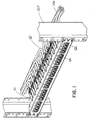
- FIG. 1 illustrates a front perspective view of the cable management support bar with strain relief clamps in the closed position to secure the cables positioned therein;
- FIG. 2 illustrates a rear perspective view of the cable management support bar with the strain relief clamps securing the cables positioned therein of FIG. 1;
- FIG. 3 illustrates an exploded view of the strain relief clamps and the cable management support bar illustrated in FIG. 1;
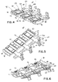
- FIG. 4 illustrates a rear top perspective view of the strain relief clamps illustrated in FIG. 3;
- FIG. 5 illustrates a front top perspective view of the strain relief clamps illustrated in FIG. 3;
- FIG. 6 illustrates a rear bottom perspective view of the strain relief clamps illustrated in FIG. 3;
- FIG. 7 illustrates a top view of the cable management support bar with strain relief clamps secured to an equipment rack
- FIG. 8 illustrates a cross sectional view of one of the strain relief clamps taken along line 8-8 of FIG. 7;
- FIG. 9 illustrates a cross sectional view of one of the strain relief clamps taken along line 9-9 of FIG. 7;
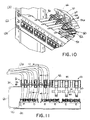
- FIG. 10 illustrates a front perspective view of the cable management support bar with the strain relief clamps in an open position
- FIG. 11 illustrates a top view of the cable management support bar with the open strain relief clamps of FIG. 10;
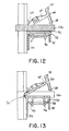
- FIG. 12 illustrates a cross sectional view of one of the strain relief clamps taken along line 12-12 of FIG. 11;
- FIG. 13 illustrates a cross sectional view of one of the strain relief clamps taken along line 13-13 of FIG. 11;
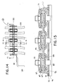
- FIG. 14 illustrates a top view of the cable management support bar with the strain relief clamps of the present invention securing a cable having a large diameter
- FIG. 15 illustrates a cross sectional view of the cable management support bar with the strain relief clamps taken along line 15-15 of FIG. 14;
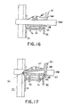
- FIG. 16 illustrates a cross sectional view of the cable management support bar with the strain relief clamps taken along line 16-16 of FIG. 14;
- FIG. 17 illustrates a cross sectional view of the cable management support bar with the strain relief clamps taken along line 17-17 of FIG. 14;
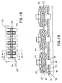
- FIG. 18 illustrates a top view of the cable management support bar with the strain relief clamps of the present invention securing a flat cable
- FIG. 19 illustrates a cross sectional view of the cable management support bar with the strain relief clamps taken along line 19-19 of FIG. 18;
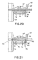
- FIG. 20 illustrates a cross sectional view of the cable management support bar with the strain relief clamps taken along line 20-20 of FIG. 18;
- FIG. 21 illustrates a cross sectional view of the cable management support bar with the strain relief clamps taken along line 21-21 of FIG. 18;
- FIG. 22 illustrates a top view of the cable management support bar with the strain relief clamps of the present invention securing a cable having a small diameter
- FIG. 23 illustrates a cross sectional view of the cable management support bar with the strain relief clamps taken along line 23-23 of FIG. 22;
- FIG. 24 illustrates a cross sectional view of the cable management support bar with the strain relief clamps taken along line 24-24 of FIG. 22;
- FIG. 25 illustrates a cross sectional view of the cable management support bar with the strain relief clamps taken along line 25-25 of FIG. 22;
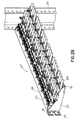
- FIG. 26 illustrates a rear perspective view of a high density patch panel with the strain relief clamps of the present invention.
- FIG. 27 illustrates a rear perspective view of the bracket and strain relief clamps used with the high density patch panel of FIG. 26.
- FIGS. 1 and 2 illustrate an exemplary application of the cable management support bar 30 and strain relief clamps 50 of the present invention.
- the strain relief clamps 50 are secured to the support bar 30 so that the strain relief clamps 50 are able to guide the cables 126 extending from the network modules 124 installed in the patch panel 122.
- the strain relief clamps 50 hold the cables 126 in place when the cables are pulled in various directions.
- the strain relief clamps 50 support the cables 126 and relieve the strain on the cables 126 as the cables 126 are routed through the rack system.
- FIG. 3 illustrates the support bar 30 and the strain relief clamps 50.
- the support bar 30 includes a horizontal member 32, a vertical member 34, a first end 36 and a second end 38.
- the first end 36 and the second end 38 have openings 40 for receiving fasteners to secure the support bar 30 to an equipment rack 120.
- each end 36, 38 of the support bar 30 is fastened to the rear of the equipment rack 120.
- the vertical member 34 of the support bar 30 extends between the first end 36 and the second end 38.
- the horizontal member 32 extends outwardly from the vertical member 34.
- the horizontal member 32 also extends between the first end 36 and the second end 38.
- the horizontal member 32 includes a plurality of apertures 42 and a plurality of slots 44 configured to receive the mounting latches 96 and projections 98, respectively, extending from the strain relief clamps 50.
- the apertures 42 and the slots 44 are arranged in a specific pattern to accommodate the maximum number of strain relief clamps 50 on the support bar 30.
- FIG. 3 also illustrates the support bar 30 with a lip 35 that extends downwardly from the free end of the horizontal member 32. It is contemplated that the support bar 30 may also be manufactured without the downwardly extending lip 35.
- FIGS. 3-6 illustrate the strain relief clamp 50 in an open position.
- the strain relief clamp 50 includes a body member 52 with a plurality of latch members 54 integrally formed with the body member 52.
- the latch members 54 are pivotally attached to a first side 84 of the body member 52 by living hinges 56. Each hinge 56 enables the latch members 54 to be freely rotated from an open position to a closed position.
- Each latch member 54 includes a latch body 60 with two latch arms 62 that extend outwardly in opposite directions from the latch body 60.
- the bottom of each latch arm 62 has a generally arcuate guide 64 that accommodates a cable when the latch members 54 are in the closed positioned.
- the free end of each latch member 54 includes a tab 66 with a latch 68 at one end for locking the strain relief clamp 50 and a release lever 70 at the opposite end for disengaging the latch 68 to unlock the strain relief clamp 50.
- the body member 52 includes a top 80, a bottom 82, first and second sides 84, 86, respectively, and first and second ends 88, 90, respectively.
- the top 80 of the body member 52 includes a plurality of cable guides 92 for housing the cables 126 in the system.
- the cable guides 92 have an arcuate shape for accommodating the cables 126 positioned therein. As will be discussed below, the arcuate cable guide 92 in the body member 52 is designed to receive cables having varying diameters.
- the top 80 of the body member 52 also includes a plurality of notches 94.
- the notches 94 have a generally rectangular shape for accommodating a portion of the latch arms 62 when the latch arms 62 are in the closed position.
- the latch members 54 extend from a first side 84 of the body member 52.
- the second side 86 of the body member 52 includes a plurality of latching teeth 100.
- the latching teeth 100 are arranged in sets that include two teeth, however, it is contemplated that the number of latching teeth may vary.
- the latching teeth 100 are positioned at spaced intervals where one set of the latching teeth 100 is aligned with one of the tabs 66 of the latch members 54. As a result, when the latch members are pivoted to a closed position, the latch tabs 68 are able to engage the latching teeth to secure the strain relief clamp in a closed position.
- the bottom 82 of the body member 52 includes a plurality of mounting latches 96 that extend downwardly from the bottom 82 of the body member 52.
- the mounting latches 96 are positioned adjacent to the underside of each of the cable guides 92.
- the mounting latches 96 are snap fit into the apertures 42 in the support bar 30 thereby securing the strain relief clamp 50 to the support bar 30 as illustrated in FIGS. 1 and 2.
- Each end 88, 90 of the body member 52 includes a projection 98 that extends downwardly from the ends 88, 90.
- the slots 44 in the support bar 30 receive the projections 98 to further align the strain relief clamp 50 to the support bar 30.
- FIGS. 7-9 illustrate the strain relief clamps 50 installed in the support bar 30 that is secured to the rear of the equipment rack 120.
- the strain relief clamps 50 are arranged such that each cable guide 92 is aligned with one of the modules 124 installed in the patch panel 122 to provide a path for the cables 126 that extend from the modules 124.
- the mounting latches 96 extending from the body member 52 of the clamp 50 are disposed within the apertures 42 in the support bar 30. The mounting latches 96 engage the bottom of the support bar 30 to secure the strain relief clamps 50 to the support bar 30.
- FIGS. 10-13 illustrate an equipment rack 120 with a number of cables 126 terminated at the modules 124 in the patch panel 122.
- the support bar 30 of the present invention is secured to the rear of the equipment rack and the strain relief clamps 50 are installed in the support bar 30 to hold the cables 126.
- each cable 126 is positioned in one of the cable guides 92 in the strain relief clamps 50.
- the latch members 54 are pivoted to a partially closed position such that the latch arms 62 are positioned partially over the cables 126 in the cable guides 92.
- the arms 62 of the latch members 54 engage the cables 126 to hold the cables 126 in place. Additionally, the latch tab 68 engages one of the latching teeth 100 to lock the strain relief clamp 50 in a closed position.
- the release lever 70 is pushed towards the hinge 56 and upwards to disengage the latch tab 68 from the locking teeth 100. Once the latch tab 68 is released, the latch member 54 may be pivoted away from the body member 52 to the open position.
- the strain relief clamps of the present invention are designed to secure cables of various sizes that may be terminated at the modules.
- the strain relief clamp is designed to clamp cables having a diameter of approximately 0.19 inch to 0.31 inch, however, it is contemplated that the clamp may be designed to accommodate cables having a smaller or larger diameter.
- the strain relief clamp may accommodate a relatively flat cable having a nominal cross section of approximately 0.365 inch by 0.165 inch.
- the strain relief clamp may also accommodate flat cables having smaller dimensions.
- FIGS. 14-17 illustrate the strain relief clamps securing cables having a large diameter
- FIGS. 18-21 illustrate the strain relief clamps securing relatively flat cables
- FIGS. 22-25 illustrate the strain relief clamps securing cables having a small diameter.
- FIG. 14 the strain relief clamps 50 are in the closed position securing a cable having a large diameter.
- FIG. 15 illustrates the cables disposed in the arcuate cable guides 92 and the latch arms 62 of the strain relief clamps 50 positioned over a top portion of the cable having a large diameter to secure the cables within the strain relief clamps.
- the latch tab 68 since the diameter of the cable is relatively large, the latch tab 68 only engages the first latching tooth to lock the strain relief clamp 50 in the closed position.
- the strain relief clamps 50 are in the closed position securing a relatively flat cable.
- the flat cable is disposed between the latching arms 62 and the cable guides 92 such that the latching arms 62 and the cable guides 92 engage the outer edges of the flat cable to secure the flat cable in the strain relief clamp.
- the latch tab 68 engages the second latching tooth to lock the strain relief clamp 50 in the closed position.
- the strain relief clamps 50 are in the closed position securing a cable having a small diameter.
- the cable is positioned in the arcuate cable guide 92 and the latching arms 62 cover the top portion of the cable to secure the cable in the strain relief clamp 50.
- the latching arms 62 are pivoted to the closed position over the cable, a portion of the latching arms 62 are disposed within the notches 94 in the top 80 of the body member 52 of the strain relief clamp 50.
- the latch tab 68 engages the bottom 82 of the body member 52 to lock the strain relief clamp 50 in the closed position.
- the strain relief clamps of the present invention hold the network cables in place and relieve the strain exerted on the cables as the cables are routed through the system.
- the strain relief clamps may be used with high density patch panels 200.
- FIG. 26 illustrates a high density patch panel frame 202 with a plurality of apertures 204 having connectors mounted therein.
- a pair of brackets 210 extend rearwardly from the ends of the patch panel frame 202.
- each bracket 210 includes an end 212 with a plurality of mounting openings 214 configured to receive fasteners to secure the bracket 210 to the equipment rack.
- a number of support bars 220 are attached to the brackets 210 such that the support bars 220 extend between the pair of brackets 210.
- the support bars 220 have an aperture 222 for receiving the strain relief clamps 50 and a number of retainers 224 for retaining the strain relief clamps 50.
- the support bars 220 are positioned at varying heights to enable the strain relief clamps 50 to accommodate the cables extending from the connectors of the high density patch panel.
- strain relief clamps may be used with angled patch panels.
- the strain relief clamps may also be installed on support bars arranged in staggered rows (see FIGS. 26 and 27) or may be installed on other devices such as rack mount trays or drawers.
Landscapes
- Engineering & Computer Science (AREA)
- Computer Networks & Wireless Communication (AREA)
- Installation Of Indoor Wiring (AREA)
- Clamps And Clips (AREA)
- Details Of Connecting Devices For Male And Female Coupling (AREA)
- Connector Housings Or Holding Contact Members (AREA)
Abstract
Description
- The present invention relates to a cable management system, and more particularly to a cable management support bar with strain relief clamps for holding cables in a cable management system.
- Telecommunication systems include equipment racks or frames to which communication connectors are mounted. The associated cabling is routed through and around the racks to another destination within the rack system or at a device. Either during installation, or at the time of revisions to the system, cables may become intertwined or bent as cables are directed through the system. This can result in undesirable strain on the cable where it is terminated to a connector module. Thus, it is desirable to provide a device that helps guide the cables and provides strain relief on the cables as the cables are directed through the system.
- The present invention is directed to a clamp that secures cables in a cable management system. The clamp includes a body member and latch members integrally formed with the body member. The body member has a number of cable guides designed to support various cables. The latch members include outwardly extending arms. The latch members pivot from an open position to a closed position where the arms are disposed over the cable guide for securing the cables positioned therein. Embodiments of the invention will now be described, by way of example, with reference to the drawings of which:
- FIG. 1 illustrates a front perspective view of the cable management support bar with strain relief clamps in the closed position to secure the cables positioned therein;
- FIG. 2 illustrates a rear perspective view of the cable management support bar with the strain relief clamps securing the cables positioned therein of FIG. 1;
- FIG. 3 illustrates an exploded view of the strain relief clamps and the cable management support bar illustrated in FIG. 1;
- FIG. 4 illustrates a rear top perspective view of the strain relief clamps illustrated in FIG. 3;
- FIG. 5 illustrates a front top perspective view of the strain relief clamps illustrated in FIG. 3;
- FIG. 6 illustrates a rear bottom perspective view of the strain relief clamps illustrated in FIG. 3;
- FIG. 7 illustrates a top view of the cable management support bar with strain relief clamps secured to an equipment rack;
- FIG. 8 illustrates a cross sectional view of one of the strain relief clamps taken along line 8-8 of FIG. 7;
- FIG. 9 illustrates a cross sectional view of one of the strain relief clamps taken along line 9-9 of FIG. 7;
- FIG. 10 illustrates a front perspective view of the cable management support bar with the strain relief clamps in an open position;
- FIG. 11 illustrates a top view of the cable management support bar with the open strain relief clamps of FIG. 10;
- FIG. 12 illustrates a cross sectional view of one of the strain relief clamps taken along line 12-12 of FIG. 11;
- FIG. 13 illustrates a cross sectional view of one of the strain relief clamps taken along line 13-13 of FIG. 11;
- FIG. 14 illustrates a top view of the cable management support bar with the strain relief clamps of the present invention securing a cable having a large diameter;
- FIG. 15 illustrates a cross sectional view of the cable management support bar with the strain relief clamps taken along line 15-15 of FIG. 14;
- FIG. 16 illustrates a cross sectional view of the cable management support bar with the strain relief clamps taken along line 16-16 of FIG. 14;
- FIG. 17 illustrates a cross sectional view of the cable management support bar with the strain relief clamps taken along line 17-17 of FIG. 14;
- FIG. 18 illustrates a top view of the cable management support bar with the strain relief clamps of the present invention securing a flat cable;
- FIG. 19 illustrates a cross sectional view of the cable management support bar with the strain relief clamps taken along line 19-19 of FIG. 18;
- FIG. 20 illustrates a cross sectional view of the cable management support bar with the strain relief clamps taken along line 20-20 of FIG. 18;
- FIG. 21 illustrates a cross sectional view of the cable management support bar with the strain relief clamps taken along line 21-21 of FIG. 18;
- FIG. 22 illustrates a top view of the cable management support bar with the strain relief clamps of the present invention securing a cable having a small diameter;
- FIG. 23 illustrates a cross sectional view of the cable management support bar with the strain relief clamps taken along line 23-23 of FIG. 22;
- FIG. 24 illustrates a cross sectional view of the cable management support bar with the strain relief clamps taken along line 24-24 of FIG. 22;
- FIG. 25 illustrates a cross sectional view of the cable management support bar with the strain relief clamps taken along line 25-25 of FIG. 22;
- FIG. 26 illustrates a rear perspective view of a high density patch panel with the strain relief clamps of the present invention; and
- FIG. 27 illustrates a rear perspective view of the bracket and strain relief clamps used with the high density patch panel of FIG. 26.
- FIGS. 1 and 2 illustrate an exemplary application of the cable
management support bar 30 andstrain relief clamps 50 of the present invention. Thestrain relief clamps 50 are secured to thesupport bar 30 so that thestrain relief clamps 50 are able to guide thecables 126 extending from thenetwork modules 124 installed in thepatch panel 122. Thestrain relief clamps 50 hold thecables 126 in place when the cables are pulled in various directions. Thus, thestrain relief clamps 50 support thecables 126 and relieve the strain on thecables 126 as thecables 126 are routed through the rack system. - FIG. 3 illustrates the
support bar 30 and thestrain relief clamps 50. Thesupport bar 30 includes ahorizontal member 32, avertical member 34, afirst end 36 and a second end 38. Thefirst end 36 and the second end 38 haveopenings 40 for receiving fasteners to secure thesupport bar 30 to anequipment rack 120. As shown in FIG. 2, eachend 36, 38 of thesupport bar 30 is fastened to the rear of theequipment rack 120. Thevertical member 34 of thesupport bar 30 extends between thefirst end 36 and the second end 38. Thehorizontal member 32 extends outwardly from thevertical member 34. Thehorizontal member 32 also extends between thefirst end 36 and the second end 38. Thehorizontal member 32 includes a plurality ofapertures 42 and a plurality ofslots 44 configured to receive themounting latches 96 andprojections 98, respectively, extending from thestrain relief clamps 50. Theapertures 42 and theslots 44 are arranged in a specific pattern to accommodate the maximum number ofstrain relief clamps 50 on thesupport bar 30. FIG. 3 also illustrates thesupport bar 30 with alip 35 that extends downwardly from the free end of thehorizontal member 32. It is contemplated that thesupport bar 30 may also be manufactured without the downwardly extendinglip 35. - FIGS. 3-6 illustrate the
strain relief clamp 50 in an open position. Thestrain relief clamp 50 includes abody member 52 with a plurality oflatch members 54 integrally formed with thebody member 52. Thelatch members 54 are pivotally attached to afirst side 84 of thebody member 52 byliving hinges 56. Eachhinge 56 enables thelatch members 54 to be freely rotated from an open position to a closed position. - Each
latch member 54 includes alatch body 60 with twolatch arms 62 that extend outwardly in opposite directions from thelatch body 60. The bottom of eachlatch arm 62 has a generallyarcuate guide 64 that accommodates a cable when thelatch members 54 are in the closed positioned. The free end of eachlatch member 54 includes atab 66 with alatch 68 at one end for locking thestrain relief clamp 50 and arelease lever 70 at the opposite end for disengaging thelatch 68 to unlock thestrain relief clamp 50. - The
body member 52 includes atop 80, abottom 82, first andsecond sides second ends body member 52 includes a plurality ofcable guides 92 for housing thecables 126 in the system. Thecable guides 92 have an arcuate shape for accommodating thecables 126 positioned therein. As will be discussed below, thearcuate cable guide 92 in thebody member 52 is designed to receive cables having varying diameters. The top 80 of thebody member 52 also includes a plurality ofnotches 94. Thenotches 94 have a generally rectangular shape for accommodating a portion of thelatch arms 62 when thelatch arms 62 are in the closed position. - As discussed above, the
latch members 54 extend from afirst side 84 of thebody member 52. Thesecond side 86 of thebody member 52 includes a plurality of latchingteeth 100. The latchingteeth 100 are arranged in sets that include two teeth, however, it is contemplated that the number of latching teeth may vary. The latchingteeth 100 are positioned at spaced intervals where one set of the latchingteeth 100 is aligned with one of thetabs 66 of thelatch members 54. As a result, when the latch members are pivoted to a closed position, thelatch tabs 68 are able to engage the latching teeth to secure the strain relief clamp in a closed position. - The bottom 82 of the
body member 52 includes a plurality of mountinglatches 96 that extend downwardly from the bottom 82 of thebody member 52. The mounting latches 96 are positioned adjacent to the underside of each of the cable guides 92. The mounting latches 96 are snap fit into theapertures 42 in thesupport bar 30 thereby securing thestrain relief clamp 50 to thesupport bar 30 as illustrated in FIGS. 1 and 2. - Each
end body member 52 includes aprojection 98 that extends downwardly from theends slots 44 in thesupport bar 30 receive theprojections 98 to further align thestrain relief clamp 50 to thesupport bar 30. - FIGS. 7-9 illustrate the strain relief clamps 50 installed in the
support bar 30 that is secured to the rear of theequipment rack 120. The strain relief clamps 50 are arranged such that eachcable guide 92 is aligned with one of themodules 124 installed in thepatch panel 122 to provide a path for thecables 126 that extend from themodules 124. As shown in FIGS. 8 and 9, the mounting latches 96 extending from thebody member 52 of theclamp 50 are disposed within theapertures 42 in thesupport bar 30. The mounting latches 96 engage the bottom of thesupport bar 30 to secure the strain relief clamps 50 to thesupport bar 30. - FIGS. 10-13 illustrate an
equipment rack 120 with a number ofcables 126 terminated at themodules 124 in thepatch panel 122. As discussed above, thesupport bar 30 of the present invention is secured to the rear of the equipment rack and the strain relief clamps 50 are installed in thesupport bar 30 to hold thecables 126. Thus, eachcable 126 is positioned in one of the cable guides 92 in the strain relief clamps 50. As shown in FIG. 10, thelatch members 54 are pivoted to a partially closed position such that thelatch arms 62 are positioned partially over thecables 126 in the cable guides 92. - Once the
latch members 54 are pivoted to the closed position, thearms 62 of thelatch members 54 engage thecables 126 to hold thecables 126 in place. Additionally, thelatch tab 68 engages one of the latchingteeth 100 to lock thestrain relief clamp 50 in a closed position. When it is desirable to open the strain relief clamp, therelease lever 70 is pushed towards thehinge 56 and upwards to disengage thelatch tab 68 from the lockingteeth 100. Once thelatch tab 68 is released, thelatch member 54 may be pivoted away from thebody member 52 to the open position. - The strain relief clamps of the present invention are designed to secure cables of various sizes that may be terminated at the modules. The strain relief clamp is designed to clamp cables having a diameter of approximately 0.19 inch to 0.31 inch, however, it is contemplated that the clamp may be designed to accommodate cables having a smaller or larger diameter. Additionally, the strain relief clamp may accommodate a relatively flat cable having a nominal cross section of approximately 0.365 inch by 0.165 inch. However, it is contemplated that the strain relief clamp may also accommodate flat cables having smaller dimensions. For example, FIGS. 14-17 illustrate the strain relief clamps securing cables having a large diameter, FIGS. 18-21 illustrate the strain relief clamps securing relatively flat cables and FIGS. 22-25 illustrate the strain relief clamps securing cables having a small diameter.
- As shown in FIG. 14, the strain relief clamps 50 are in the closed position securing a cable having a large diameter. FIG. 15 illustrates the cables disposed in the arcuate cable guides 92 and the
latch arms 62 of the strain relief clamps 50 positioned over a top portion of the cable having a large diameter to secure the cables within the strain relief clamps. As illustrated in FIG. 17, since the diameter of the cable is relatively large, thelatch tab 68 only engages the first latching tooth to lock thestrain relief clamp 50 in the closed position. - As shown in FIG. 18, the strain relief clamps 50 are in the closed position securing a relatively flat cable. Thus, as illustrated in FIG. 19, the flat cable is disposed between the latching
arms 62 and the cable guides 92 such that the latchingarms 62 and the cable guides 92 engage the outer edges of the flat cable to secure the flat cable in the strain relief clamp. Also, since the flat cable occupies less space in the strain relief clamp than the cable having a large diameter, thelatch tab 68 engages the second latching tooth to lock thestrain relief clamp 50 in the closed position. - As shown in FIG. 22, the strain relief clamps 50 are in the closed position securing a cable having a small diameter. As illustrated in FIG. 23, the cable is positioned in the
arcuate cable guide 92 and the latchingarms 62 cover the top portion of the cable to secure the cable in thestrain relief clamp 50. When the latchingarms 62 are pivoted to the closed position over the cable, a portion of the latchingarms 62 are disposed within thenotches 94 in the top 80 of thebody member 52 of thestrain relief clamp 50. As illustrated in FIG. 25, since the diameter of the cable is relatively small, thelatch tab 68 engages the bottom 82 of thebody member 52 to lock thestrain relief clamp 50 in the closed position. - The strain relief clamps of the present invention hold the network cables in place and relieve the strain exerted on the cables as the cables are routed through the system. As shown in FIG. 26, the strain relief clamps may be used with high
density patch panels 200. FIG. 26 illustrates a high densitypatch panel frame 202 with a plurality ofapertures 204 having connectors mounted therein. A pair ofbrackets 210 extend rearwardly from the ends of thepatch panel frame 202. As shown in FIG. 27, eachbracket 210 includes anend 212 with a plurality of mountingopenings 214 configured to receive fasteners to secure thebracket 210 to the equipment rack. A number of support bars 220 are attached to thebrackets 210 such that the support bars 220 extend between the pair ofbrackets 210. The support bars 220 have anaperture 222 for receiving the strain relief clamps 50 and a number ofretainers 224 for retaining the strain relief clamps 50. The support bars 220 are positioned at varying heights to enable the strain relief clamps 50 to accommodate the cables extending from the connectors of the high density patch panel. - Additionally, the strain relief clamps may be used with angled patch panels. The strain relief clamps may also be installed on support bars arranged in staggered rows (see FIGS. 26 and 27) or may be installed on other devices such as rack mount trays or drawers.
- Furthermore, while the particular preferred embodiments of the present invention have been shown and described, it will be obvious to those skilled in the art that changes and modifications may be made without departing from the teaching of the invention. The matter set forth in the foregoing description and accompanying drawings is offered by way of illustration only and not as limitation. The actual scope of the invention is intended to be defined in the following claims when viewed in their proper perspective based on the prior art.
Claims (10)
- A clamp for securing cables in a cable management system, the clamp comprising:a body member having at least one cable guide; andat least one latch member integrally formed with the body member, the latch member having at least one arm;wherein the at least one latch member pivots from an open position to a closed position where the at least one arm is disposed over the at least one cable guide for securing a cable positioned therein.
- The clamp of claim 1, wherein the body member includes mounting latches for securing the clamp to the cable management system.
- A device for securing cables in a cable management system, the device comprising:a bar;a clamp secured to the bar, the clamp having a body member having at least one cable guide; and at least one latch member integrally formed with the body member, the latch member having arms; wherein the at least one latch member pivots from an open position to a closed position where the arms are disposed over the at least one cable guide for securing a cable.
- The device of claim 9, wherein the body member has two cable guides.
- The device of claim 3 or 4, wherein the bar has a horizontal member with a plurality of apertures for receiving the clamp and preferably wherein the body member includes mounting latches that are adapted to be received in the aperture of the bar for securing the clamp to the bar.
- The clamp or device of any preceding claim, wherein the at least one latch member is pivotally attached to the body member by a hinge or wherein the at least one cable guide is arcuate or wherein the arms have an arcuate bottom surface.
- The clamp or device of any preceding claim, wherein the body member has a plurality of teeth and the at least one latch member has a latch for lockingly engaging one of the plurality of teeth to lock the clamp in the closed position or wherein the at least one latch member has a release lever for disengaging the latch from the teeth or wherein the body member has a notch for accommodating the arms of the latch member in the closed position.
- A cable management system comprising:a patch panel having a frame with a plurality of apertures for mounting connectors therein;a pair of brackets extending rearwardly from the patch panel frame;a support bar attached to the brackets; andclamps secured to the support bar, the clamps having a body member with at least one cable guide and at least one latch member integrally formed with the body member; the latch member having arms, wherein the at least one latch member pivots from an open position to a closed position where the arms are disposed over the at least one cable guide for securing a cable therein.
- The cable management system of claim 8, further comprising a plurality of support bars.
- The cable management system of claim 9, wherein the plurality of support bars are attached to the brackets at varying heights.
Applications Claiming Priority (1)
| Application Number | Priority Date | Filing Date | Title |
|---|---|---|---|
| US11/038,322 US7345241B2 (en) | 2005-01-18 | 2005-01-18 | Cable management support bar with strain relief clamps |
Publications (2)
| Publication Number | Publication Date |
|---|---|
| EP1681752A2 true EP1681752A2 (en) | 2006-07-19 |
| EP1681752A3 EP1681752A3 (en) | 2010-09-08 |
Family
ID=36129462
Family Applications (1)
| Application Number | Title | Priority Date | Filing Date |
|---|---|---|---|
| EP06250249A Withdrawn EP1681752A3 (en) | 2005-01-18 | 2006-01-18 | Cable management support bar with strain relief clamps |
Country Status (3)
| Country | Link |
|---|---|
| US (2) | US7345241B2 (en) |
| EP (1) | EP1681752A3 (en) |
| JP (2) | JP2006275283A (en) |
Cited By (5)
| Publication number | Priority date | Publication date | Assignee | Title |
|---|---|---|---|---|
| DE102007039353B3 (en) * | 2007-08-21 | 2009-02-19 | Adc Gmbh | Cable management and equipment for telecommunications and data technology |
| DE102008018171A1 (en) * | 2008-04-03 | 2009-10-08 | Komos Gmbh | Data technology distributor |
| WO2010025901A1 (en) * | 2008-09-05 | 2010-03-11 | Adc Gmbh | Patch panel assembly |
| WO2020012059A1 (en) * | 2018-07-12 | 2020-01-16 | Maeihaeniemi Janne | Fixing device to secure an rj-interface |
| WO2020136257A1 (en) | 2018-12-27 | 2020-07-02 | Arcelik Anonim Sirketi | A household appliance comprising a cable protector |
Families Citing this family (51)
| Publication number | Priority date | Publication date | Assignee | Title |
|---|---|---|---|---|
| US6971909B2 (en) * | 2003-12-30 | 2005-12-06 | Ortronics, Inc. | Angled patch panel assembly |
| US7693387B2 (en) * | 2007-04-05 | 2010-04-06 | C.E. Communication Systems, Inc. | Cable management system |
| DE102007017286A1 (en) * | 2007-04-12 | 2008-10-16 | Leoni Bordnetz-Systeme Gmbh | Cable guide |
| AU2008310300B2 (en) * | 2007-10-09 | 2013-05-02 | Clipsal Australia Pty Ltd | A cable manager for rack mounted patch panels and the like |
| US8263867B2 (en) | 2008-01-07 | 2012-09-11 | Chatsworth Products, Inc. | Cable management accessories |
| USD626817S1 (en) | 2008-01-07 | 2010-11-09 | Chatsworth Products, Inc. | Accessory bracket for fiber management |
| GB2468823B (en) | 2008-01-07 | 2012-10-24 | Chatsworth Prod Inc | Vertical cable manager |
| AU2009204505A1 (en) | 2008-01-07 | 2009-07-16 | Chatsworth Products, Inc. | Apparatus and method for organizing cables in a cabinet |
| DE102008016631B4 (en) * | 2008-04-01 | 2014-12-11 | BSH Bosch und Siemens Hausgeräte GmbH | Cable holder, household appliance and method for laying cables in a household appliance |
| US8363998B2 (en) * | 2009-01-27 | 2013-01-29 | Panduit Corp. | Vertical cable management system |
| WO2011088297A1 (en) * | 2010-01-15 | 2011-07-21 | Afl Telecommunications Llc | Cable tie-down bracket |
| RU2462400C2 (en) * | 2010-08-16 | 2012-09-27 | Федеральное Государственное Унитарное Предприятие "Государственный научно-производственный ракетно-космический центр "ЦСКБ-Прогресс" (ФГУП "ГНПРКЦ "ЦСКБ-Прогресс") | Device for electromechanical linkage between fixed structural parts of spacecraft |
| US20120273627A1 (en) * | 2011-04-26 | 2012-11-01 | Panduit Corp. | Horizontal Cable Manager |
| US9556972B2 (en) | 2011-07-15 | 2017-01-31 | Commscope Technologies Llc | Adjustable cable manager |
| US8404974B1 (en) | 2011-11-17 | 2013-03-26 | Hubbell Incorporated | Stuffer cap for patch panel of rack system |
| US8882536B2 (en) | 2012-01-27 | 2014-11-11 | Chatsworth Products, Inc. | Power distribution unit with interchangeable outlet adapter types |
| US9054449B2 (en) | 2012-01-27 | 2015-06-09 | Chatsworth Products, Inc. | Cable retention system for power distribution unit |
| US20130215581A1 (en) | 2012-01-27 | 2013-08-22 | Chatsworth Products, Inc. | Board-mounted circuit breakers for electronic equipment enclosures |
| WO2014071021A1 (en) * | 2012-10-31 | 2014-05-08 | Adc Telecommunications, Inc. | Anchoring cables to rack with cable clamp arrangements |
| US9698529B1 (en) * | 2013-02-28 | 2017-07-04 | Amazon Technologies, Inc. | Cable holder for system serviceabilty |
| WO2014164205A1 (en) | 2013-03-13 | 2014-10-09 | Adc Telecommunications, Inc. | Anchoring cables to rack with self-locking cable clamp arrangements |
| US9293862B2 (en) | 2013-08-26 | 2016-03-22 | Panduit Corp. | Patch cord plug organizer |
| WO2015034811A1 (en) * | 2013-09-06 | 2015-03-12 | Corning Optical Communications LLC | Optical fiber cassette systems with fiber retaining covers |
| ES2707730T3 (en) * | 2013-09-13 | 2019-04-04 | Te Connectivity Corp | Adjustable cable managers |
| US9253912B2 (en) * | 2013-12-23 | 2016-02-02 | Brocade Communications Systems, Inc. | Ejector and cable management system and method |
| US9451729B2 (en) * | 2013-12-23 | 2016-09-20 | Dell Products, L.P. | Modular application of peripheral panels as expansion sleeves and cable management components within a rack-based information handling system |
| JP2017520887A (en) | 2014-06-05 | 2017-07-27 | チャッツワース プロダクツ、インク. | Electrical outlet with locking mechanism |
| US9444237B2 (en) * | 2014-10-06 | 2016-09-13 | Ross Video Limited | Cable management apparatus and method |
| US10122157B1 (en) | 2015-05-14 | 2018-11-06 | Sticnstac, LLC | Panel wire support brackets |
| JP6237718B2 (en) * | 2015-07-07 | 2017-11-29 | 日本電気株式会社 | Cable holding structure, rack cabinet, and method |
| EP3398003A1 (en) * | 2015-12-31 | 2018-11-07 | CommScope Connectivity Belgium BVBA | Cable fixation devices and methods |
| US9832904B1 (en) * | 2016-03-28 | 2017-11-28 | Amazon Technologies, Inc. | Patch panel assembly |
| DE102017113124A1 (en) * | 2017-06-14 | 2018-12-20 | Abb Schweiz Ag | Connecting device for laying cables and network cables |
| US11452223B2 (en) * | 2017-11-22 | 2022-09-20 | Telefonaktiebolaget Lm Ericsson (Publ) | Cable sealing assembly |
| US10666029B2 (en) * | 2018-01-23 | 2020-05-26 | Cable Management Solutions Inc. | Cable management system and method for photovoltaic systems and other cable-dependent systems |
| US10547145B2 (en) | 2018-02-05 | 2020-01-28 | Chatworth Products, Inc. | Electric receptacle with locking feature |
| US10340674B1 (en) * | 2018-03-19 | 2019-07-02 | A'n D Cable Products Inc. | Reversible cable support bar |
| USD891228S1 (en) * | 2019-02-06 | 2020-07-28 | Hubert North America Services, LLC | Support rail for food pan |
| US10944355B2 (en) | 2019-03-20 | 2021-03-09 | Cable Management Solutions Inc. | Cable management systems and methods for photovoltaic systems and other cable-dependent systems |
| US10916078B2 (en) * | 2019-03-27 | 2021-02-09 | Hugo Wendling | Integrated access control system |
| US11417992B2 (en) | 2019-06-12 | 2022-08-16 | Ortronics, Inc. | Modular edge patching system |
| US11184688B2 (en) * | 2019-11-04 | 2021-11-23 | Cisco Technology, Inc. | Minimal touch post for multi-layer cable routing |
| DE102020112989B4 (en) * | 2020-05-13 | 2024-03-07 | Yaasa Gmbh | Cable management system and workstation system |
| US11269145B2 (en) | 2020-07-29 | 2022-03-08 | Google Llc | Cable connection structure for fiber optic hardware management |
| US11835163B2 (en) | 2021-02-12 | 2023-12-05 | Belden Canada Ulc | Strain relief assembly |
| US12394967B2 (en) * | 2021-03-18 | 2025-08-19 | Lennard A. Gumaer | High density multi-position network termination assembly and process of manufacture |
| US12282201B2 (en) | 2022-02-15 | 2025-04-22 | Google Llc | Splicing tray utilized in fiber optic patch panel assembly for fiber optic cable connection management |
| US20240022057A1 (en) * | 2022-07-12 | 2024-01-18 | Preformed Line Products Co. | Segmented cable tangent clamp |
| AT526809B1 (en) | 2023-01-11 | 2025-12-15 | Tgw Logistics Gmbh | Cable fixing device and control device for a conveyor device with such a cable fixing device |
| US12328838B2 (en) * | 2023-02-13 | 2025-06-10 | Iontra Inc | Rack ears and methods of using the same |
| US12155192B2 (en) | 2023-03-22 | 2024-11-26 | Logitech Europe S.A. | Cable management and retention system for a computing device |
Citations (1)
| Publication number | Priority date | Publication date | Assignee | Title |
|---|---|---|---|---|
| US5535969A (en) | 1994-03-14 | 1996-07-16 | Illinois Tool Works Inc. | Fold over scissors clip |
Family Cites Families (36)
| Publication number | Priority date | Publication date | Assignee | Title |
|---|---|---|---|---|
| FR2247925A5 (en) * | 1973-10-10 | 1975-05-09 | Itw De France | |
| DE2619610A1 (en) * | 1976-05-04 | 1977-11-17 | Licentia Gmbh | Single piece lead securing clamp - consists of hinged lever and latch made of plastics by injection moulding with integral hinges |
| JPS57172503A (en) * | 1981-04-17 | 1982-10-23 | Pioneer Electronic Corp | Cord fixture |
| JPS57194974A (en) * | 1981-05-27 | 1982-11-30 | Hitachi Ltd | High-temperature liquid injected tank |
| US4623102A (en) * | 1983-12-14 | 1986-11-18 | Apple Adhesives, Inc. | Article clamp |
| US4564163A (en) * | 1984-06-04 | 1986-01-14 | Trw United-Carr Limited | Retaining clip |
| US4643389A (en) * | 1984-12-27 | 1987-02-17 | American Hospital Supply Corporation | Tubing occlusion clip |
| JPH0396487A (en) * | 1989-09-08 | 1991-04-22 | Iseki & Co Ltd | Bonnet open and close device for tractor |
| JPH0396487U (en) * | 1990-01-23 | 1991-10-02 | ||
| JP2563935Y2 (en) * | 1991-02-14 | 1998-03-04 | 株式会社ニフコ | Mounting fixture |
| JPH04264376A (en) * | 1991-02-18 | 1992-09-21 | Fujikura Ltd | Connector and method for connecting shielding wire to connector |
| JP2561975B2 (en) * | 1991-03-13 | 1996-12-11 | 富士通株式会社 | Cable unit and storage frame |
| US5127082A (en) | 1991-03-22 | 1992-06-30 | The Siemon Company | Fiber optic patch panel |
| DE4207281C1 (en) * | 1992-03-07 | 1993-04-29 | Rittal-Werk Rudolf Loh Gmbh & Co Kg, 6348 Herborn, De | |
| JPH0628313U (en) * | 1992-09-07 | 1994-04-15 | 株式会社東郷製作所 | Holders such as pipes |
| US5494194A (en) * | 1993-12-10 | 1996-02-27 | White Consolidated Industries, Inc. | Viscous material dispenser |
| JPH09508718A (en) | 1994-02-08 | 1997-09-02 | ミニフレックス リミテッド | Cable routing equipment |
| DE19504253C1 (en) * | 1994-10-20 | 1996-04-04 | Hans Simon | Cable clamp |
| US5559922A (en) | 1995-02-28 | 1996-09-24 | Lucent Technologies Inc. | Wire guide and optical fiber storage spool assembly |
| US5566269A (en) | 1995-05-30 | 1996-10-15 | The Whitaker Corporation | Strain relieving holder for optical fiber cable |
| US5566268A (en) | 1995-05-30 | 1996-10-15 | The Whitaker Corporation | Strain relieving holder for optical fiber cable |
| US5669590A (en) * | 1995-12-04 | 1997-09-23 | Yazaki Corporation | Retaining clip with multiple clamps |
| US5613655A (en) * | 1996-02-13 | 1997-03-25 | Illinois Tool Works Inc. | Method and apparatus for a double clasp retention clip |
| US5820048A (en) * | 1996-04-09 | 1998-10-13 | Illinois Tool Works Inc. | Side latching hinge mechanism |
| US6009223A (en) | 1997-09-02 | 1999-12-28 | Siecor Corporation | Bracket assembly for strain relief of optical fiber jumpers |
| EP1021050A1 (en) | 1999-01-14 | 2000-07-19 | Thomas & Betts International, Inc. | Improvements in or relating to patch panels |
| JP3346349B2 (en) | 1999-08-23 | 2002-11-18 | 住友電装株式会社 | Long wire storage structure inside protector |
| US6456772B1 (en) | 1999-09-21 | 2002-09-24 | Avaya Technology Corp. | System for removable attachment of two objects |
| US6278830B1 (en) | 2000-01-12 | 2001-08-21 | Ortronics, Inc. | Bend limiting fiber management clip |
| US6461052B1 (en) | 2000-03-17 | 2002-10-08 | Ortronics, Inc. | Optical fiber management module assembly |
| US6768858B2 (en) | 2001-03-16 | 2004-07-27 | Adc Telecommunications, Inc. | Cable clip with segregator and method |
| US6539161B2 (en) | 2001-03-16 | 2003-03-25 | Adc Telecommunications, Inc. | Cable routing clip |
| US6600106B2 (en) * | 2001-07-11 | 2003-07-29 | Adc Telecommunications, Inc. | Cable management bar and patch panel |
| US6592266B1 (en) | 2001-10-04 | 2003-07-15 | Advanced Fibre Communications, Inc. | Fiber optic cable connector clip |
| JP4021640B2 (en) * | 2001-10-12 | 2007-12-12 | 河村電器産業株式会社 | Cable storage unit |
| JP2004239325A (en) * | 2003-02-04 | 2004-08-26 | Takeuchi Kogyo Kk | Fixture |
-
2005
- 2005-01-18 US US11/038,322 patent/US7345241B2/en not_active Expired - Lifetime
-
2006
- 2006-01-18 EP EP06250249A patent/EP1681752A3/en not_active Withdrawn
- 2006-01-18 JP JP2006009720A patent/JP2006275283A/en not_active Withdrawn
-
2008
- 2008-01-17 US US12/015,980 patent/US7619164B2/en not_active Expired - Fee Related
-
2012
- 2012-04-05 JP JP2012086664A patent/JP5296902B2/en not_active Expired - Fee Related
Patent Citations (1)
| Publication number | Priority date | Publication date | Assignee | Title |
|---|---|---|---|---|
| US5535969A (en) | 1994-03-14 | 1996-07-16 | Illinois Tool Works Inc. | Fold over scissors clip |
Cited By (9)
| Publication number | Priority date | Publication date | Assignee | Title |
|---|---|---|---|---|
| DE102007039353B3 (en) * | 2007-08-21 | 2009-02-19 | Adc Gmbh | Cable management and equipment for telecommunications and data technology |
| WO2009024236A1 (en) * | 2007-08-21 | 2009-02-26 | Adc Gmbh | Cable routing device and unit for telecommunication and data technology |
| US8253019B2 (en) | 2007-08-21 | 2012-08-28 | Adc Gmbh | Cable routing device and unit for telecommunication and data technology |
| DE102008018171A1 (en) * | 2008-04-03 | 2009-10-08 | Komos Gmbh | Data technology distributor |
| DE102008018171B4 (en) * | 2008-04-03 | 2011-04-28 | Komos Gmbh | Data technology distributor |
| WO2010025901A1 (en) * | 2008-09-05 | 2010-03-11 | Adc Gmbh | Patch panel assembly |
| US8290330B2 (en) | 2008-09-05 | 2012-10-16 | Adc Gmbh | Patch panel assembly |
| WO2020012059A1 (en) * | 2018-07-12 | 2020-01-16 | Maeihaeniemi Janne | Fixing device to secure an rj-interface |
| WO2020136257A1 (en) | 2018-12-27 | 2020-07-02 | Arcelik Anonim Sirketi | A household appliance comprising a cable protector |
Also Published As
| Publication number | Publication date |
|---|---|
| JP5296902B2 (en) | 2013-09-25 |
| US20060171075A1 (en) | 2006-08-03 |
| US7345241B2 (en) | 2008-03-18 |
| JP2006275283A (en) | 2006-10-12 |
| JP2012160464A (en) | 2012-08-23 |
| EP1681752A3 (en) | 2010-09-08 |
| US7619164B2 (en) | 2009-11-17 |
| US20080108231A1 (en) | 2008-05-08 |
Similar Documents
| Publication | Publication Date | Title |
|---|---|---|
| US7345241B2 (en) | Cable management support bar with strain relief clamps | |
| US8216004B2 (en) | Vertical cable management system with ribcage structure | |
| US8363996B2 (en) | Mounting system for telecommunications panels | |
| US11683613B2 (en) | Telecommunications panel with patching device installation features | |
| US9699936B1 (en) | Cable management assembly | |
| US6728461B1 (en) | Optical fiber cable manager | |
| US20020197045A1 (en) | Cable management brackets and cabinet | |
| US9091831B2 (en) | Rack-mountable telecommunications patch panel | |
| US8290330B2 (en) | Patch panel assembly | |
| US7369740B2 (en) | Cable management system with spring latch | |
| US7764857B2 (en) | Cable management system with twist latch | |
| CA2533486A1 (en) | Cable management rack | |
| AU2002254952B2 (en) | Mounting tray for IDC junction modules | |
| US20070232134A1 (en) | Protective cover for rack mounted networking equipment | |
| AU2002254952A1 (en) | Mounting tray for IDC junction modules | |
| CN111712973B (en) | Method and system for managing connector array | |
| EP2862363B1 (en) | Assembly and method for managing components of a telecommunication system | |
| NZ702952B2 (en) | Assembly and method for managing components of a telecommunication system |
Legal Events
| Date | Code | Title | Description |
|---|---|---|---|
| PUAI | Public reference made under article 153(3) epc to a published international application that has entered the european phase |
Free format text: ORIGINAL CODE: 0009012 |
|
| AK | Designated contracting states |
Kind code of ref document: A2 Designated state(s): AT BE BG CH CY CZ DE DK EE ES FI FR GB GR HU IE IS IT LI LT LU LV MC NL PL PT RO SE SI SK TR |
|
| AX | Request for extension of the european patent |
Extension state: AL BA HR MK YU |
|
| PUAL | Search report despatched |
Free format text: ORIGINAL CODE: 0009013 |
|
| AK | Designated contracting states |
Kind code of ref document: A3 Designated state(s): AT BE BG CH CY CZ DE DK EE ES FI FR GB GR HU IE IS IT LI LT LU LV MC NL PL PT RO SE SI SK TR |
|
| AX | Request for extension of the european patent |
Extension state: AL BA HR MK YU |
|
| 17P | Request for examination filed |
Effective date: 20110308 |
|
| AKX | Designation fees paid |
Designated state(s): AT BE BG CH CY CZ DE DK EE ES FI FR GB GR HU IE IS IT LI LT LU LV MC NL PL PT RO SE SI SK TR |
|
| STAA | Information on the status of an ep patent application or granted ep patent |
Free format text: STATUS: THE APPLICATION HAS BEEN WITHDRAWN |
|
| 18W | Application withdrawn |
Effective date: 20130108 |