EP1681517A1 - Indoor unit of air conditioner - Google Patents
Indoor unit of air conditioner Download PDFInfo
- Publication number
- EP1681517A1 EP1681517A1 EP04787815A EP04787815A EP1681517A1 EP 1681517 A1 EP1681517 A1 EP 1681517A1 EP 04787815 A EP04787815 A EP 04787815A EP 04787815 A EP04787815 A EP 04787815A EP 1681517 A1 EP1681517 A1 EP 1681517A1
- Authority
- EP
- European Patent Office
- Prior art keywords
- panel
- opening
- indoor unit
- closing mechanism
- air conditioner
- Prior art date
- Legal status (The legal status is an assumption and is not a legal conclusion. Google has not performed a legal analysis and makes no representation as to the accuracy of the status listed.)
- Granted
Links
Images





Classifications
-
- F—MECHANICAL ENGINEERING; LIGHTING; HEATING; WEAPONS; BLASTING
- F24—HEATING; RANGES; VENTILATING
- F24F—AIR-CONDITIONING; AIR-HUMIDIFICATION; VENTILATION; USE OF AIR CURRENTS FOR SCREENING
- F24F1/00—Room units for air-conditioning, e.g. separate or self-contained units or units receiving primary air from a central station
- F24F1/0007—Indoor units, e.g. fan coil units
-
- F—MECHANICAL ENGINEERING; LIGHTING; HEATING; WEAPONS; BLASTING
- F24—HEATING; RANGES; VENTILATING
- F24F—AIR-CONDITIONING; AIR-HUMIDIFICATION; VENTILATION; USE OF AIR CURRENTS FOR SCREENING
- F24F1/00—Room units for air-conditioning, e.g. separate or self-contained units or units receiving primary air from a central station
- F24F1/0007—Indoor units, e.g. fan coil units
- F24F1/0043—Indoor units, e.g. fan coil units characterised by mounting arrangements
- F24F1/0057—Indoor units, e.g. fan coil units characterised by mounting arrangements mounted in or on a wall
-
- F—MECHANICAL ENGINEERING; LIGHTING; HEATING; WEAPONS; BLASTING
- F24—HEATING; RANGES; VENTILATING
- F24F—AIR-CONDITIONING; AIR-HUMIDIFICATION; VENTILATION; USE OF AIR CURRENTS FOR SCREENING
- F24F1/00—Room units for air-conditioning, e.g. separate or self-contained units or units receiving primary air from a central station
- F24F1/0007—Indoor units, e.g. fan coil units
- F24F1/0059—Indoor units, e.g. fan coil units characterised by heat exchangers
- F24F1/0063—Indoor units, e.g. fan coil units characterised by heat exchangers by the mounting or arrangement of the heat exchangers
-
- F—MECHANICAL ENGINEERING; LIGHTING; HEATING; WEAPONS; BLASTING
- F24—HEATING; RANGES; VENTILATING
- F24F—AIR-CONDITIONING; AIR-HUMIDIFICATION; VENTILATION; USE OF AIR CURRENTS FOR SCREENING
- F24F1/00—Room units for air-conditioning, e.g. separate or self-contained units or units receiving primary air from a central station
- F24F1/0007—Indoor units, e.g. fan coil units
- F24F1/0059—Indoor units, e.g. fan coil units characterised by heat exchangers
- F24F1/0067—Indoor units, e.g. fan coil units characterised by heat exchangers by the shape of the heat exchangers or of parts thereof, e.g. of their fins
-
- F—MECHANICAL ENGINEERING; LIGHTING; HEATING; WEAPONS; BLASTING
- F24—HEATING; RANGES; VENTILATING
- F24F—AIR-CONDITIONING; AIR-HUMIDIFICATION; VENTILATION; USE OF AIR CURRENTS FOR SCREENING
- F24F13/00—Details common to, or for air-conditioning, air-humidification, ventilation or use of air currents for screening
- F24F13/20—Casings or covers
Definitions
- An indoor unit of an air conditioner according to a ninth aspect of the present invention is the indoor unit of the air conditioner according to any one of the sixth through the eighth aspects, wherein the opening and closing mechanism is configured such that it distributes the driving force of the drive portion to the first opening and closing mechanism and the second opening and closing mechanism.
- An indoor unit of an air conditioner according to a twelfth aspect of the present invention is the indoor unit of the air conditioner according to the first through the eleventh aspects, wherein the main body casing is provided with a control component.
- the drive portion has a motor that is connected to the control component and that moves the first movable panel.
- the main body casing has a temporary fixing portion, with which the drive portion is temporarily fixed.
- the front grill has a fixing portion with which the temporarily fixed drive portion is fixed.
- This refrigerant circuit of this air conditioner 1 mainly comprises an indoor heat exchanger 20, an accumulator 31, a compressor 32, a four-way switching valve 33, an outdoor heat exchanger 30, and a motor-operated expansion valve 34.
- step S6 of mounting the front grill assembly 6 the front grill assembly 6 is mounted to the main body part 4.
- the front grill assembly 6 covers the main body part 4 from the front of the main body part 4, and is fixed to the main body part 4 by screwing or fitting
- first opening and closing mechanism 63 and the second opening and closing mechanism 64 are provided respectively at the inner surfaces of the left and the right sides of the front grill 60; however, the positions of the first opening and closing mechanism 63 and the second opening and closing mechanism 64 are not limited to those above. A different arrangement may be possible depending on the shape of the front grill 60 or the position of the front panel 7.
Landscapes
- Engineering & Computer Science (AREA)
- Chemical & Material Sciences (AREA)
- Combustion & Propulsion (AREA)
- Mechanical Engineering (AREA)
- General Engineering & Computer Science (AREA)
- Physics & Mathematics (AREA)
- Thermal Sciences (AREA)
- Air Filters, Heat-Exchange Apparatuses, And Housings Of Air-Conditioning Units (AREA)
- Air-Flow Control Members (AREA)
- Air-Conditioning Room Units, And Self-Contained Units In General (AREA)
Abstract
Description
- The present invention relates to an indoor unit of an air conditioner.
- Some indoor units of air conditioners are equipped with a movable panel, a drive portion, and an opening and closing mechanism. The movable panel is, for example, a panel that moves so as to open and close an opening such as an intake port. The drive portion generates a driving force to move the movable panel. The opening and closing mechanism is a mechanism to move the movable panel by a driving force of the drive portion, and for example, it comprises a gear which transmits a driving force of a motor and the like. In addition, indoor units of air conditioners are equipped with a main body casing that houses a heat exchanger, a ventilation fan, and the like, and the drive portion is often provided in the main body casing. Consequently, with conventional indoor units of air conditioners, in many cases, the opening and closing mechanism is also provided in the main body casing (refer to Patent Document 1).
- On the other hand, many of the recent indoor units of air conditioners are equipped with a front grill that is mounted to the main body casing. The front grill is mounted to the front of the main body casing, and has openings such as an intake port and an outlet. With such an indoor unit of the air conditioner, the above described movable panel is movably provided so as to open and close the openings of the front grill. Then, the movable panel opens and closes the openings by the drive portion and the opening and closing mechanism provided in the main body casing. In other words, even when the front grill is mounted to the main body casing, since the drive portion is provided in the main body casing, the opening and closing mechanism is also provided in the main body casing in many cases.
- Japanese Utility Model Publication No. H07-12821
- However, when the opening and closing mechanism is provided in the main body casing as described above, there is the risk that the mounting accuracy between the movable panel and the front grill will be reduced. In other words, when the opening and closing mechanism is provided in the main body casing, the movable panel to be opened and closed by the opening and closing mechanism will be positioned with the main body as a reference. Consequently, there is a risk that the mounting accuracy between the movable panel that opens and closes the openings of the front grill and the front grill will be reduced.
- It is therefore an object of the present invention is to provide an indoor unit of an air conditioner that is capable of improving the mounting accuracy between the front grill and the movable panel.
- An indoor unit of an air conditioner according to a first aspect of the present invention includes a main body casing, a front grill, a first movable panel, a drive portion, and an opening and closing mechanism. The front grill is provided forward of the main body casing, and has a first opening. The first movable panel is capable of moving so as to open and close the first opening. The drive portion generates a driving force to move the first movable panel. The opening and closing mechanism is provided at the front grill, and moves the first movable panel by the driving force of the drive portion to open and close the first opening.
- With this indoor unit of the air conditioner, the opening and closing mechanism is provided at the front grill not in the main body casing. Consequently, the first movable panel that is moved by the opening and closing mechanism is positioned with the front grill as a reference rather than the main body casing. Consequently, with this indoor unit of the air conditioner, the mounting accuracy between the front grill and the first movable panel can be improved.
- An indoor unit of an air conditioner according to a second aspect of the present invention is the indoor unit of the air conditioner according to the first aspect, wherein at least when the front grill is mounted to the main body casing, the drive portion is provided in the main body casing.
- With this indoor unit of the air conditioner, at least when the front grill is mounted to the main body casing, the drive portion is provided in the main body casing. With such type of conventional indoor unit of an air conditioner, in many cases, the opening and closing mechanism is also provided in the main body casing in accordance with the position of the drive portion. However, with this indoor unit of the air conditioner, the opening and closing mechanism is provided at the front grill not in the main body casing. Consequently, with this indoor unit of the air conditioner, even if it is configured such that the drive portion is provided in the main body casing, the mounting accuracy between the front grill and the first movable panel can be improved.
- An indoor unit of an air conditioner according to a third aspect of the present invention is the indoor unit of the air conditioner of the first or the second aspect, wherein the opening and closing mechanism has a supporting member. The supporting member is mounted to the first movable panel and supports the first movable panel.
- With this indoor unit of the air conditioner, the opening and closing mechanism has the supporting member. In other words, the supporting member that supports the first movable panel is provided at the front grill. Consequently, the first movable panel supported by the supporting member is positioned with the front grill as a reference rather than the main body casing. Consequently, with this indoor unit of the air conditioner, the mounting accuracy between the front grill and the first movable panel can be improved.
- An indoor unit of an air conditioner according to a fourth aspect of the present invention is the indoor unit of the air conditioner according to any one of the first through the third aspects, wherein the opening and closing mechanism has a speed reducing mechanism. The speed reducing mechanism transmits the driving force of the drive portion to the first movable panel.
- With this indoor unit of the air conditioner, the opening and closing mechanism has the speed reducing mechanism. In other words, the speed reducing mechanism that transmits the driving force to the first movable panel is provided at the front grill. Consequently, the first movable panel to which the driving force is transmitted by the speed reducing mechanism is positioned with the front grill as a reference rather than the main body casing. Consequently, with this indoor unit of the air conditioner, the mounting accuracy between the front grill and the first movable panel can be improved.
- An indoor unit of an air conditioner according to a fifth aspect of the present invention is the indoor unit of the air conditioner according to any one of the first through the fourth aspects, wherein the opening and closing mechanism has a converting mechanism. The converting mechanism converts a rotary motion transmitted from the driving unit to the opening and closing movements of the first movable panel.
- With this indoor unit of the air conditioner, the opening and closing mechanism has the converting mechanism. In other words, the converting mechanism that converts the rotary motion transmitted from the driving unit to the opening and closing movements of the first movable panel is provided at the front grill. Consequently, the first movable panel that is opened and closed by the converting mechanism is positioned with the front grill as a reference rather than the main body casing. Consequently, with this indoor unit of the air conditioner, the mounting accuracy between the front grill and the first movable panel can be improved.
- An indoor unit of an air conditioner according to a sixth aspect of the present invention is the indoor unit of the air conditioner according to the first through the fifth aspects, wherein the opening and closing mechanism has a first opening and closing mechanism and a second opening and closing mechanism. The first opening and closing mechanism moves one end of the first movable panel by the driving force of the drive portion. The second opening and closing mechanism moves the other end of the first movable panel by the driving force of the drive portion.
- With this indoor unit of the air conditioner, the both ends of the first movable panel are moved by the first opening and closing mechanism and the second opening and closing mechanism. Consequently, the first movable panel can be moved in a stable manner.
- An indoor unit of an air conditioner according to a seventh aspect of the present invention is the indoor unit of the air conditioner according to the sixth aspect, wherein the first opening and closing mechanism and the second opening and closing mechanism each are formed as a unit.
- With this indoor unit of the air conditioner, the first opening and closing mechanism and the second opening and closing mechanism each are formed as a unit. Consequently, with this indoor unit of the air conditioner, the assemblability can be improved.
- An indoor unit of an air conditioner according to an eighth aspect of the present invention is the indoor unit of the air conditioner according to the seventh aspect, wherein the first opening and closing mechanism and the second opening and closing mechanism are provided such that they are respectively fixed to inner surfaces of the left and right sides of the front grill.
- With this indoor unit of the air conditioner, the first opening and closing mechanism and the second opening and closing mechanism are provided such that they are respectively fixed to the inner surfaces of the left and right sides of the front grill. Consequently, when mounting the front grill, there is a low risk that the first opening and closing mechanism and the second opening and closing mechanism will interfere with the mounting. Consequently, with this indoor unit of the air conditioner, the assemblability can be further improved.
- An indoor unit of an air conditioner according to a ninth aspect of the present invention is the indoor unit of the air conditioner according to any one of the sixth through the eighth aspects, wherein the opening and closing mechanism is configured such that it distributes the driving force of the drive portion to the first opening and closing mechanism and the second opening and closing mechanism.
- With this indoor unit of the air conditioner, the driving force from the single drive portion can be distributed to the first opening and closing mechanism and the second opening and closing mechanism. Consequently, it is easy to precisely synchronize the opening and closing movements of the first opening and closing mechanism and the second opening and closing mechanism. As a result, with this indoor unit of the air conditioner, the opening and closing movements can be performed in a more stable manner.
- An indoor unit of an air conditioner according to a tenth aspect of the present invention is the indoor unit of the air conditioner according to the first through the ninth aspects, wherein the front grill further includes a second opening. In addition, the indoor unit of the air conditioner further comprises a second movable panel. The second movable panel is capable of moving so as to open and close the second opening. Further, the opening and closing mechanism moves the first movable panel to open and close the first opening and also moves the second movable panel to open and close the second opening, by the driving force of the drive portion.
- With this indoor unit of the air conditioner, the opening and closing mechanism moves the first movable panel to open and close the first opening and also moves the second movable panel to open and close the second opening, by the driving force of the drive portion. Consequently, it is possible to link the first movable panel and the second movable panel and move them together by the opening and closing mechanism. Consequently, with this indoor unit of the air conditioner, the opening and closing movements of the first movable panel and the second movable panel can be performed in a timely manner.
- An indoor unit of an air conditioner according to an eleventh aspect of the present invention is the indoor unit of the air conditioner according to any one of the first through the tenth aspects, wherein the main body casing has a second gear. The second gear is disposed such that it engages with a first gear included in the opening and closing mechanism in a state in which the front grill is mounted to the main body casing, and the second gear transmits the driving force of the drive portion to the opening and closing mechanism.
- With this indoor unit of the air conditioner, the second gear is disposed such that it engages with the first gear included in the opening and closing mechanism in the state in which the front grill is mounted to the main body casing, and the second gear transmits the driving force of the drive portion to the opening and closing mechanism. Consequently, mounting the front grill to the main body casing enables the second gear to be engaged with the first gear. Consequently, with this indoor unit of the air conditioner, the assemblability can be improved.
- An indoor unit of an air conditioner according to a twelfth aspect of the present invention is the indoor unit of the air conditioner according to the first through the eleventh aspects, wherein the main body casing is provided with a control component. In addition, the drive portion has a motor that is connected to the control component and that moves the first movable panel. In addition, the main body casing has a temporary fixing portion, with which the drive portion is temporarily fixed. Further, the front grill has a fixing portion with which the temporarily fixed drive portion is fixed.
- Some indoor units of air conditioners are provided with a movable panel that moves by a driving force of a motor in a casing, and the motor is connected to a control component and is controlled by the control component. With an indoor unit of an air conditioner, in which a casing is divided into a main body casing and a front grill, a control component is housed in the main body casing, and the front grill is provided with a movable panel (refer to Japanese Laid-Open Patent Application No. 2003-21495 (third Figure)), in order to have a front panel function as a movable panel, such structures as one by which a drive portion having a motor is fixed to the main body casing and one by which a drive portion is fixed to the front grill may be conceivable.
- However, in case of the structure in which the drive portion is fixed to the main body casing, there is a risk that the assembly accuracy of the indoor unit of the air conditioner will be reduced. In other words, in the case where the drive portion to move the movable panel is fixed to the main body casing and the movable panel is provided at the front grill, the alignment between the drive portion and the movable panel will be difficult, and it will easily generate an error in the assembly accuracy between the main body casing and the front grill.
- In addition, in case of the structure in which the drive portion is fixed to the front grill, there is a risk that the wiring procedure will be difficult. In other words, since the drive portion has the motor, it needs to be connected to the control component. However, since the control component is housed in the main body casing, in the case where the drive portion is fixed to the front grill, the wiring will extend from the main body casing to the front grill. Consequently, there is a risk that the wiring procedure will be complicated and difficult.
- With this indoor unit of the air conditioner, the drive portion can be temporarily fixed to the main body casing. As a result, the wiring procedure for connecting the control component and the drive portion can be prevented from becoming complicated. In addition, the drive portion that is temporarily fixed to the main body casing can be fixed to the front grill after the front grill is mounted to the main body casing. As a result, the alignment between the drive portion and the front grill will be easy, and the assembly accuracy among the main body casing, the front grill, and the drive portion can be improved. As discussed above, with this indoor unit of the air conditioner, the assembly accuracy can be improved, and also the wiring procedure can be easily conducted.
- An indoor unit of an air conditioner according to a thirteenth aspect of the present invention is the indoor unit of the air conditioner according to the twelfth aspect, wherein the drive portion is temporarily fixed such that the drive portion is capable of moving to a position where the drive portion is to be fixed with the fixing portion when the drive portion is fixed with the fixing portion.
- With this indoor unit of the air conditioner, the drive portion is temporarily fixed such that the drive portion is capable of moving to a position where the drive portion is to be fixed with the fixing portion when the drive portion is fixed with the fixing portion. Consequently, with this indoor unit of the air conditioner, it will be easy to align the drive portion with the front grill.
- An indoor unit of an air conditioner according to a fourteenth aspect of the present invention is the indoor unit of the air conditioner according to the twelfth or the thirteenth aspect, wherein the temporary fixing portion has a clip portion which holds the drive portion and temporarily fixes the drive portion.
- With this indoor unit of the air conditioner, the drive portion is temporarily fixed with the clip portion. Consequently, with this indoor unit of the air conditioner, the temporary fixation can be achieved by a simple component such as the clip portion.
-
- Figure 1 is a view of a refrigerant circuit of an air conditioner.
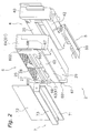
- Figure 2 is an exploded perspective view of an indoor unit
- Figure 3(a) is a front view of the indoor unit.
- Figure 3(b) is a side cross sectional view of the indoor unit.
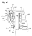
- Figure 4 is an exploded perspective view showing the vicinity of a left side end of the indoor unit.
- Figure 5 is a side view of a driving machine.
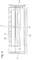
- Figure 6 is a view of a front grill assembly seen from the reverse side.
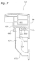
- Figure 7 is a side view of a first opening and closing mechanism.
- Figure 8 is a view showing the opening and closing movements of a first panel and a second panel.
- Figure 9 is a flow showing a method for assembling the indoor unit.
-
- 1
- air conditioner
- 2
- indoor unit
- 27
- first intake port (first opening)
- 29
- outlet portion (second opening)
- 41
- driving machine (drive portion)
- 42
- main body casing
- 43
- panel opening and closing motor (motor)
- 45
- second driving machine gear (second gear)
- 60
- front grill
- 61
- opening and closing mechanism
- 62
- fixing portion
- 63
- first opening and closing mechanism
- 64
- second opening and closing mechanism
- 66
- power transmission gear (first gear)
- 68
- second panel supporting member (supporting member, speed reducing mechanism, converting mechanism)
- 71
- first panel (second movable panel)
- 72
- second panel (first movable panel)
- 490
- locking clip (temporary fixing portion, clip portion)
- 630
- first opening and closing gear (speed reducing mechanism, converting mechanism)
- 631
- second opening and closing gear (speed reducing mechanism, converting mechanism)
- Figure 1 shows a schematic view of the configuration of an air condition 1 and a refrigerant circuit thereof according to a first embodiment of the present invention.
- This air conditioner 1 comprises an
indoor unit 2, which is attached to a wall surface or the like in the room, and anoutdoor unit 3 installed outdoors. - This refrigerant circuit of this air conditioner 1 mainly comprises an
indoor heat exchanger 20, anaccumulator 31, acompressor 32, a four-way switching valve 33, anoutdoor heat exchanger 30, and a motor-operatedexpansion valve 34. - The
indoor heat exchanger 20 provided inside theindoor unit 2 exchanges heat with the air with which it comes in contact. In addition, theindoor unit 2 is provided with anindoor fan 21 that draws in the indoor air, passes the air through theindoor heat exchanger 20 for heat exchange, and then discharges the air into the room. Theindoor fan 21 is rotatably driven by anindoor fan motor 22 provided inside theindoor unit 2. The configuration of theindoor unit 2 will be described in detail later. - The
outdoor unit 3 comprises thecompressor 32, the four-way switching valve 33 connected to a discharge side of thecompressor 32, theaccumulator 31 connected to an intake side of thecompressor 32, theoutdoor heat exchanger 30 connected to the four-way switching valve 33, and the motor-operatedexpansion valve 34 connected to theoutdoor heat exchanger 30. The motor-operatedexpansion valve 34 is connected to apipe 23 via aliquid shutoff valve 36, and is connected to one end of theindoor heat exchanger 20 via thispipe 23. In addition, the four-way switching valve 33 is connected to apipe 24 via agas shutoff valve 37, and is connected to the other end of theindoor heat exchanger 20 via thispipe 24. In addition, theoutdoor unit 3 is provided with anoutdoor fan 38 for externally discharging air after its heat has been exchanged by theoutdoor heat exchanger 30. Theoutdoor fan 38 is rotatably driven by anoutdoor fan motor 39. - Figure 2 shows an exploded perspective view of the
indoor unit 2. - The
indoor unit 2 is a wall-hanging type indoor unit, which is installed on a side wall of the room, and theindoor unit 2 mainly comprises amain body part 4, anoutlet assembly 5, afront grill assembly 6, and afront panel 7. - The
main body part 4 has theindoor heat exchanger 20, the indoor fan 21 (refer to Figure 1), the indoor fan motor 22 (refer to Figure 1), anelectrical component box 40, a driving machine 41 (refer to Figure 4), and amain body casing 42. - The
indoor heat exchanger 20, theindoor fan 21, and theindoor fan motor 22 are mounted to themain body casing 42. As shown in Figure 3(b), as for theindoor heat exchanger 20 and theindoor fan 21 in the side view, theindoor fan 21 is disposed in the center of theindoor unit 2, and theindoor heat exchanger 20 having an inverted V-shape is disposed such that it covers an upper half of theindoor fan 21. In addition, the indoor fan motor 22 (not shown) is disposed to a right side of theindoor fan 21 in the front view. Note that Figure 3(b) is a side cross sectional view of theindoor unit 2. - As shown in Figure 2, the
electrical component box 40 is mounted to themain body casing 42, and is disposed to the right side of theindoor heat exchanger 20, theindoor fan 21, and theindoor fan motor 22 in the front view. Theelectrical component box 40 houses a control board therein, and the control board controls each component that is necessary for heating and cooling operations and the like of theindoor unit 2. - As shown in Figure 4, the driving machine 41 (drive portion) is disposed near a left side end of the
main body casing 42, and generates a driving force to move thefront panel 7. As shown in Figure 5, the drivingmachine 41 includes a panel opening and closing motor 43 (motor), afirst drive gear 44, a second drive gear 45 (second gear), and adrive casing 46. - The panel opening and closing
motor 43 is connected to a control component housed in theelectrical component box 40 via acable 430, and serves as a source of the driving force to move thefront panel 7. - The
first drive gear 44 transmits the rotation of the panel opening and closingmotor 43 to thesecond drive gear 45. - The
second drive gear 45 has a portion that is exposed from thedrive casing 46, and is disposed so as to engage with a power transmission gear 66 (refer to Figure 6) included in an opening andclosing mechanism 61, in a state in which afront grill 60 is mounted to themain body casing 42. Consequently, by mounting thefront grill 60 to themain body part 4 and fixing the drivingmachine 41 to a later described fixing portion 62 (refer to Figure 4), thesecond drive gear 45 can be easily engaged with thepower transmission gear 66. Thesecond drive gear 45 transmits the rotation of the panel opening and closingmotor 43 via thefirst drive gear 44 to thepower transmission gear 66, and transmits the driving force of the panel opening and closingmotor 43 to the opening andclosing mechanism 61. - The
drive casing 46 houses the above mentioned panel opening and closingmotor 43, thefirst drive gear 44, and thesecond drive gear 45. In addition, thedrive casing 46 includes alocking hole 461 and a fixedportion 462. - The
locking hole 461 is an opening, which is provided in thedrive casing 46, and to which alocking clip 490 on the main body casing 42 shown in Figure 4 will be inserted. Two lockingholes 461 are provided in thedrive casing 46, and each of them is formed larger than thelocking clip 490. Consequently, in a state in which the locking clips 490 are inserted to the locking holes 461, the drivingmachine 41 is not completely fixed in an unmovable manner, but the drivingmachine 41 is temporarily fixed in a slightly movable manner. Therefore, when regularly fixing the drivingmachine 41, which is conducted after the temporary fixation, the drivingmachine 41 can be easily positioned. - The fixed
portion 462 is a portion configured to be fixed to the fixingportion 62 of thefront grill 60, and it has a screw hole. The fixedportion 462 is screwed to the fixingportion 62 provided at thefront grill 60. Unlike the temporary fixation between the lockinghole 461 and thelocking clip 490, the fixation between the fixedportion 462 and the fixingportion 62 is a fixation to securely fix the drivingmachine 41 to thefront grill 60 to prevent the drivingmachine 41 from moving. - The
main body casing 42 is provided with theindoor heat exchanger 20, theindoor fan 21, theindoor fan motor 22, theelectrical component box 40, and the drivingmachine 41. Theindoor heat exchanger 20, theindoor fan 21, theindoor fan motor 22, and theelectrical component box 40 are fixed to themain body casing 42, and the drivingmachine 41 is temporarily fixed thereto. Themain body casing 42 is molded from a resin material and has a shape such that it covers lower and back portions and the left side portion of theindoor fan 21. As shown in Figure 4, themain body casing 42 includes anindoor fan housing 47, aback portion 48, and aleft side portion 49. Note that in Figure 4, views of theindoor heat exchanger 20 and theindoor fan 21 are omitted in order to facilitate understanding. - The
indoor fan housing 47 is a portion that houses theindoor fan 21 and theindoor fan motor 22, and theindoor fan housing 47 supports theindoor heat exchanger 20 that is mounted from above theindoor fan 21. Theindoor fan motor 22 to be disposed to the right side of theindoor fan 21 is fixed to a portion near a right side end of theindoor fan housing 47, and theelectrical component box 40 is fixed to the further right side thereof (refer to Figure 2). A lower portion of theindoor fan housing 47 is a portion to which theoutlet assembly 5 is fixed, and the lower portion is provided with an opening (not shown) which communicates with a space in which theindoor fan 21 housed. As a result of mounting theoutlet assembly 5 to the lower portion of theindoor fan housing 47, the space of theindoor fan housing 47, in which theindoor fan 21 is housed, will communicate with the outlet 26 (refer to Figure 3(b)). - The
back portion 48 covers the back of theindoor fan 21 and theindoor heat exchanger 20, and closes a backside of theindoor unit 2. - The
left side portion 49 is a portion to which the drivingmachine 41 will be temporarily fixed. Theleft side portion 49 is provided near a left side end of theindoor fan housing 47, and is disposed such that it faces left side ends of theindoor fan 21 and theindoor heat exchanger 20, which are mounted to theindoor fan housing 47. A left side surface of theleft side portion 49 is provided with thelocking clip 490, with which the drivingmachine 41 is temporarily fixed. Two lockingclips 490 are provided to correspond to the locking holes 461, and the locking clips 490 protrude from the left side surface of theleft side portion 49 to the left, in other words, the locking clips 490 protrudes from theleft side portion 49 to the side opposite theindoor fan 21. The drivingmachine 41 is temporarily fixed to the main body casing 42 with the locking clips 490, before thefront grill 60 is mounted to themain body casing 42. Each lockinghole 461 in the drivingmachine 41, to which eachlocking clip 490 will be inserted, is formed larger than thelocking clip 490 as described above. Consequently, the drivingmachine 41, which is in a state of being temporarily fixed with the locking clips 490 and the locking holes 461, is temporarily fixed in a slightly movable manner. When the drivingmachine 41 is fixed with the fixingportion 62 of the later describedfront grill 60, the drivingmachine 41 is temporarily fixed with thelocking clip 490 such that the drivingmachine 41 is capable of moving to a position where the drivingmachine 41 will be fixed with the fixingportion 62. - The
outlet assembly 5 shown in Figure 2 is mounted to themain body part 4 and configures the outlet 26 (refer to Figure 3 (b)). Theoutlet 26 configured by theoutlet assembly 5 is an opening wherethrough passes the air that is passed through theindoor heat exchanger 20 and is blown out into the room by theindoor fan 21. Theoutlet 26 has a horizontally long shape in the front view. In addition, theoutlet 26 is disposed near a lower portion of theindoor unit 2 and at the front of theindoor unit 2. When theindoor unit 2 is shut down, theoutlet 26 is closed by a first panel 71 (second movable panel) of thefront panel 7, which will be described later. - The
outlet assembly 5 has ahorizontal flap 50 and a flap motor 51 (refer to Figure 4). Thehorizontal flap 50 has a plate-like shape that is long in the longitudinal direction of theindoor unit 2, and guides the air that is blown out from theoutlet 26. Thehorizontal flap 50 has a rotation axis that is parallel to the longitudinal direction of theindoor unit 2, and by being driven by theflap motor 51 and rotated about the rotation axis, thehorizontal flap 50 changes the air direction in which the air is guided. In addition, by moving so as to be parallel to the horizontal plane, thehorizontal flap 50 configures the base of theindoor unit 2, with the base being parallel to the horizontal plane. - The
front grill assembly 6 is mounted to themain body part 4 from the front, and covers the front and side surfaces of themain body part 4. Thefront grill assembly 6 has thefront grill 60 and the opening andclosing mechanism 61. - The
front grill 60 is molded from a resin material, and has a shape that is thin and a generally rectangular parallelepiped with the entire backside open. Thefront grill 60 has a shape that is horizontally long and generally rectangular in the front view, and has a cross-sectional shape that is long in an up and down direction and generally rectangular in the side view. Thefront grill 60 is mounted to themain body part 4 such that it covers a front portion, left and right side portions, and upper and lower portions of themain body part 4. In addition, thefront grill 60 is provided with theintake portion 25 and the outlet portion 29 (second opening). - The
intake portion 25 is provided with an opening wherethrough passes the air that is drawn in from inside the room into theindoor unit 2 by theindoor fan 21, and theintake portion 25 has a first intake port 27 (first opening) and asecond intake port 28. Thefirst intake port 27 is provided across a portion from near the center of the front of thefront grill 60 to a top portion thereof, and is disposed such that it faces a front side of theindoor heat exchanger 20. When theindoor unit 2 is shut down, thefirst intake port 27 is closed by a second panel 72 (first movable panel) of thefront panel 7, which will be described later. Thesecond intake port 28 is configured by a plurality of slits that are long in the longitudinal direction of thefront grill 60, and is provided at the top of thefront grill 60. - The
outlet portion 29 is an opening provided at a lower portion of thefront grill 60, and together with theoutlet assembly 5, theoutlet portion 29 configures theoutlet 26. Theoutlet portion 29 is closed by thefirst panel 71 of thefront panel 7, which will be described later. - In addition, as shown in Figure 4, the fixing
portion 62 is provided at the front of thefront grill 60. The fixingportion 62 is a portion where the fixedportion 462 of the temporarily fixed drivingmachine 41 will be fixed, and the fixingportion 62 has a screw hole. The screw hole is provided near a left side end of the front of thefront grill 60, and is disposed at a position which generally faces a screw hole in the fixedportion 462 of the drivingmachine 41 that is being temporarily fixed to themain body part 4. However, in the temporary fixation step, the screw hole in the fixedportion 462 and the screw hole in the fixingportion 62 do not have to completely coincide with each other. Instead, in the regular fixation step in which the fixedportion 462 and the fixingportion 62 are fixed, the drivingmachine 41 being temporarily fixed can simply be moved such that the screw hole in the fixedportion 462 will coincide with the screw hole in the fixingportion 62. The fixingportion 62 and the fixedportion 462 are fixed by threading a screw through the screw hole in the fixedportion 462 and the screw hole in the fixingportion 62. - At portions near both sides ends of the front of the
front grill 60, there are providedslits 600 to 603 that extend in an up and down direction. Theseslits 600 to 603 are disposed such that there are a total of four, two on the left and two on the right, separated above and below. Protruding from theseslits 600 to 603 are portions of a firstpanel supporting member 67 and a secondpanel supporting member 68, which will be described later. Thefirst panel 71 and thesecond panel 72 of thefront panel 7 are respectively fixed to the above mentioned portions of the firstpanel supporting member 67 and the secondpanel supporting member 68. - The opening and
closing mechanism 61 shown in Figure 2 is a mechanism for moving thefront panel 7 by the driving force of the drivingmachine 41 to open and close thefirst intake port 27 and theoutlet 26. The opening andclosing mechanism 61 is configured by a plurality of members having a gear portion. The opening andclosing mechanism 61 functions as a speed reducing mechanism that transmits the driving force of the drivingmachine 41 to thefirst panel 71 and thesecond panel 72. In addition, the opening andclosing mechanism 61 functions as a converting mechanism that converts a rotary motion transmitted from the drivingmachine 41 into the opening and closing movements of thefirst panel 71 and thesecond panel 72. As shown in Figure 6, the opening andclosing mechanism 61 is provided at the back of thefront grill 60, and has a first opening andclosing mechanism 63, a second opening andclosing mechanism 64, and apower transmission shaft 65. - The first opening and
closing mechanism 63 is mounted to the back of the left side surface of thefront panel 7, and supports a portion near a left side end of thefirst panel 71 and a portion near a left side end of thesecond panel 72, which will be described later. Note that the "left-right" here means the "left-right" when theindoor unit 2 is seen in the front view, and since Figure 6 shows thefront grill 60 seen from the reverse side, the left-right in Figure 6 is reversed from that in the front view. When opening and closing thefirst panel 71 and thesecond panel 72, the first opening andclosing mechanism 63 transmits the driving force of the drivingmachine 41 to the portion near the left side end of thefirst panel 71 and to the portion near the left side end of thesecond panel 72, so that these portions will move. This will result in the opening and closing movements of thefirst panel 71 and thesecond panel 72. - The second opening and
closing mechanism 64 is mounted to the back of a right side surface of thefront panel 7, and supports a portion near a right side end of thefirst panel 71 and a portion near a right side end of thesecond panel 72, which will be described later. When opening and closing thefirst panel 71 and thesecond panel 72, the second opening andclosing mechanism 64 transmits the driving force of the drivingmachine 41 to the portion near the right side end of thefirst panel 71 and to the portion near the right side end of thesecond panel 72, so that these portions will move. This will result in the opening and closing movements of thefirst panel 71 and thesecond panel 72. - The
power transmission shaft 65 is a member for distributing and transmitting the driving force of the drivingmachine 41 to the first opening andclosing mechanism 63 and the second opening andclosing mechanism 64. Thepower transmission shaft 65 is mounted to the back of the front of the firstfront grill 60 such that it can freely rotate about an axis that is parallel to the longitudinal direction of theindoor unit 2. Both ends of thepower transmission shaft 65 are respectively connected to the first opening andclosing mechanism 63 and the second opening andclosing mechanism 64, and the power transmission gear 66 (first gear) is provided therebetween. Thepower transmission gear 66 is provided near the first opening andclosing mechanism 63, and is disposed such that it engages with thesecond drive gear 45 of the drivingmachine 41 in a state in which thefront grill 60 is mounted to themain body part 4. In this way, the opening andclosing mechanism 61 is configured such that it distributes, by thepower transmission shaft 65, the driving force of drivingmachine 41 to the first opening andclosing mechanism 63 and the second opening andclosing mechanism 64. - The configuration of the first opening and
closing mechanism 63 is described in detail below; it should be noted that the structure of the second opening andclosing mechanism 64 is symmetric to that of the first opening andclosing mechanism 63. - As shown in Figure 7, the first opening and
closing mechanism 63 has a first opening and closing gear 630 (speed reducing mechanism, converting mechanism), a second opening and closing gear 631 (speed reducing mechanism, converting mechanism), and the firstpanel supporting member 67, and the second panel supporting member 68 (supporting member, speed reducing mechanism, converting mechanism). In addition, the first opening andclosing mechanism 63 has a first opening andclosing mechanism casing 69 for housing these gears and members, and is formed as a unit. - The first opening and
closing gear 630 is fixed to an end of thepower transmission shaft 65, and transmits the driving force of the drivingmachine 41, which is transmitted via thepower transmission shaft 65, to the second opening andclosing gear 631. - The second opening and
closing gear 631 engages with the first opening andclosing gear 630, afirst gear portion 670 of the firstpanel supporting member 67, and asecond gear portion 680 of the secondpanel supporting member 68, and transmits the driving force transmitted from the first opening andclosing gear 630 to both the firstpanel supporting member 67 and secondpanel supporting member 68. - The first
panel supporting member 67, which is mounted to thefirst panel 71, is a flat plate shape member that supports thefirst panel 71. The firstpanel supporting member 67 is provided such that it can move in an up and down direction, and it is capable of moving thefirst panel 71 linearly in an up and down direction. The firstpanel supporting member 67 has astraight portion 671 in a linear shape, which extends parallel to an up and down direction, and acurved portion 672, which curves from a lower portion of thestraight portion 671 toward the front of theindoor unit 2. Also, thecurved portion 672 has a tip portion that protrudes forward of thefront grill 60 through theslit 601 provided at the front of the front grill 60 (refer to Figure 4). To this tip potion of thecurved portion 672 is fixed the portion near the left side end of thefirst panel 71. In addition, at thestraight portion 671, there is provided thefirst gear portion 670. Thefirst gear portion 670 is a rack gear that extends in an up and down direction, and converts a rotary motion of the second opening andclosing gear 631 to a linear motion in an up and down direction. As a result, the rotary motion of the drivingmachine 41 is converted to the linear motion of thefirst panel 71 in an up and down direction. - The second
panel supporting member 68, which is mounted to thesecond panel 72, is a flat plate shape member that supports thesecond panel 72. The secondpanel supporting member 68 is provided such that it can move in a front and back direction, and it is capable of moving thesecond panel 72 in a front and back direction. In detail, the secondpanel supporting merriber 68 draws a gentle circular arc as it moves in a front and back direction. In other words, when thesecond panel 72 moves forward, thesecond panel 72 moves such that its upper end leans forward, whereas when thesecond panel 72 moves backward, thesecond panel 72 moves such that the upper end leaning forward will return to its original position and thesecond panel 72 becomes parallel to an up and down direction (refer to Figure 8). The secondpanel supporting member 68 is integrally molded from a resin material, and has thesecond gear portion 680 and aplate member 681. - The
second gear portion 680 is provided such that it protrudes from inside theplate member 681, and it engages with the second opening andclosing gear 631. Thesecond gear portion 680 is a rack gear that extends in a front and back direction drawing a gentle circular arc. Thesecond gear portion 680 converts the rotary motion of the second opening andclosing gear 631 to a circular arc motion and transmits the driving force of the drivingmachine 41 to thesecond panel 72. - The
plate member 681 is provided at the outer sides (left sides) of the first opening andclosing gear 630, the second opening andclosing gear 631, and the firstpanel supporting member 67. Theplate member 681 covers the outer sides of the first opening andclosing gear 630, the second opening andclosing gear 631, and the firstpanel supporting member 67. A front end of theplate member 681 protrudes forward through theslit 600 that is provided at a front surface of thefront panel 7. To this front end is fixed the portion near the left side end of thesecond panel 72 and thereby the portion near the left side end of thesecond panel 72 is supported. Theplate member 681 moves such that it draws a gentle circular arc as mentioned above by the driving force of the drivingmachine 41 transmitted to thesecond gear portion 680. As for the opening movement of thesecond panel 72, theplate member 681 moves thesecond panel 72 away from thefirst intake port 27 by further protruding from theslit 600 forward of thefront grill 60. Specifically, as for the open state of thesecond panel 72, theplate member 681 protrudes greatly from theslit 600 forward of thefront grill 60 and covers sides of a gap between thesecond panel 72 and the front grill 60 (refer to Figure 8). As a result, theplate member 681 can prevent a room occupant from inserting his or her hand into the gap between thesecond panel 72 and thefront grill 60 from a side of the gap. In addition, since theplate member 681 is located at the outer sides of thesecond gear portion 680, the first opening andclosing gear 630, the second opening andclosing gear 631, and the like, a room occupant is prevented from touching thesecond gear portion 680, the first opening andclosing gear 630, the second opening andclosing gear 631, and the like, with his or her hand. - As shown in Figure 3(a), a
front panel 7 covers generally the entire front of thefront grill 60. Thefront panel 7 covers theoutlet 26 and thefirst intake port 27 in the front view, and opens and closes theoutlet 26 and thefirst intake port 27. Thefront panel 7 is a panel assembly, which is an aggregation of a plurality of seamless panels, and thefront panel 7 has thefirst panel 71, thesecond panel 72, and athird panel 73. - The
first panel 71 is movably disposed at the front lower portion of thefront grill 60 so as to open and close theoutlet 26, and thefirst panel 71 is disposed such that it covers theoutlet 26. Thefirst panel 71 is supported at the portions near both right and left ends thereof by the opening andclosing mechanism 61 such that it can move parallel to an up and down direction, and thefirst panel 71 opens and closes theoutlet 26. Thefirst panel 71 is a member in a rectangular, flat plate shape without a seam, and the width thereof is substantially equal to the width W of thefront grill 60 in the front view. The front side of thefirst panel 71 is formed in a generally flat shape with a smooth texture without a concave or convex portion, opening such as a hole, or the like. Thisfirst panel 71 will be parallel to an up and down direction as shown in Figure 3(a) and Figure 8(a) in a state in which theoutlet 26 is closed by thefirst panel 71. In addition, in this state, thefirst panel 71 has a projected area that is larger than theoutlet 26 in the front view. Consequently, thefirst panel 71 completely covers the front lower portion of thefront grill 60 including theoutlet 26, in the state in which theoutlet 26 is closed by thefirst panel 71. In addition, thefirst panel 71 is molded from a transparent resin mixed with luminous particles such as pearl particles, and thefirst panel 71 has a transparent resin layer mixed with such particles. Also, on the back of the transparent resin layer, there is provided a paint layer to which a color scheme, pattern, and the like are applied. This paint layer is formed by applying paint on the back of thefirst panel 71. In this way, thefirst panel 71 has a highly attractive design. By being disposed at the front where it is easily seen by a room occupant, thefirst panel 71 functions as a design panel which enhances the design of theindoor unit 2. - The
second panel 72 is formed as a separate body from thefirst panel 71. Thesecond panel 72 is movably disposed at a front upper portion of thefront grill 60 so as to open and close thefirst intake port 27, and thesecond panel 72 is disposed such that it covers thefirst intake port 27. Thesecond panel 72 is supported at the portions near both the right and left ends thereof by the opening andclosing mechanism 61 such that it can move in a front and back direction. Thesecond panel 72 opens thefirst intake port 27 by moving away from thefirst intake port 27 and closes thefirst intake port 27 by moving close to thefirst intake port 27. Thesecond panel 72 is a member in a rectangular, flat plate shape without a seam, and in the front view, the width thereof is substantially equal to the width W of thefront grill 60 including thefirst intake port 27. The front side of thesecond panel 72 is formed in a generally flat shape with a smooth texture without a concave or convex portion, opening such as a hole, or the like. Thissecond panel 72 will be parallel to an up and down direction as shown in Figure 3(a) and Figure 8(a), in a state in which thefirst intake port 27 is closed by thesecond panel 72. In addition, thesecond panel 72 has a projected area that is larger than thefirst intake port 27 in the front view. Consequently, thesecond panel 72 covers the front upper half portion of thefront grill 60 including thefirst intake port 27, in the state in which thefirst intake port 27 is closed by thesecond panel 72. In addition, as in the case with thefirst panel 71, thesecond panel 72 is molded from a transparent resin mixed with luminous particles such as pearl particles, and thefirst panel 71 has a transparent resin layer mixed with such particles. Also, on the back of the transparent resin layer, there is provided a paint layer to which a color scheme, pattern, and the like are applied. This paint layer is formed by applying paint on the back of thesecond panel 72. In this way, thesecond panel 72 has a highly attractive design. By being disposed at the front where it is easily seen by a room occupant, thesecond panel 72 functions as a design panel which enhances the design of theindoor unit 2. - The
third panel 73 is disposed between thefirst panel 71 and thesecond panel 72. Thethird panel 73 has a seamless rectangular shape in the front view. Thethird panel 73 has a width W that is substantially equal to that of thefront grill 60, and has a length in an up and down direction that is substantially equal to that of thefirst panel 71. The front side of thethird panel 73 is formed in a generally flat shape with a smooth texture without a concave or convex portion, opening such as a hole, or the like. As shown in Figure 8(a), portions near left and right ends of thethird panel 73 are respectively fixed to left and right side surfaces of thefront grill 60, and thethird panel 73 is disposed such that a front surface portion thereof is spaced apart from the front of thefront grill 60 in a front and back direction. In other words, behind the front surface portion of thethird panel 73, there is formed a gap between there and thefront grill 60. This gap is formed slightly larger than the thickness of thefirst panel 71 disposed below, and the gap serves as a space for housing thefirst panel 71 that moves to open theoutlet 26. In addition, thethird panel 73 is molded from an opaque resin material. - In this way, in the state in which the
outlet 26 is closed by thefirst panel 71, thefirst panel 71 completely covers the front lower portion of thefront grill 60 including theoutlet 26, and in the state in which thefirst intake port 27 is closed by thesecond panel 72, thesecond panel 72 completely covers the front upper portion of thefront grill 60 including thefirst intake port 27. In addition, thefirst panel 71, thesecond panel 72, and thethird panel 73 are disposed such that they are aligned above and below one another. In the state in which theoutlet 26 and thefirst intake port 27 are closed, they are disposed so as to configure a generally flat, rectangular plane. In the state in which theoutlet 26 and thefirst intake port 27 are closed, thefront panel 7 configured by thefirst panel 71, thesecond panel 72, and thethird panel 73 cover the generally entire front of theindoor unit 2, and only the seams created at the borderlines of thefirst panel 71, thesecond panel 72, and thethird panel 73 appear. In other words, only the horizontally extending seams created at the borderline between thefirst panel 71 and thethird panel 73 and at the borderline between thesecond panel 72 and thethird panel 73 appear in the front view. Further, thefirst panel 71, thesecond panel 72, and thethird panel 73 are parallel to an up and down direction, and in the state in which theoutlet 26 and thefirst intake port 27 are closed by thefront panel 7, thefront panel 7 forms a flat surface that is parallel to an up and down direction. With thisindoor unit 2 of the air conditioner 1, since thefront panel 7 is formed to have such a flat shape, the aesthetic appearance is enhanced. - When the
indoor unit 2 is shut down, thefront panel 7 is in a state of closing theoutlet 26 and thefirst intake port 27 as described above. When theindoor unit 2 starts operating, first, theindoor fan 21 is started at a low rotation speed. Then, thefirst panel 71 and thesecond panel 72 move, and theoutlet 26 and thefirst intake port 27 are opened. As a result, a volume of air to be drawn into theindoor unit 2 is ensured, and also air is blown out in the horizontal direction. Below, a description is provided mainly focusing on the movements of thefront panel 7 based on Figures 8(a), 8(b), and 8(c). Note that Figures 8(a), 8(b), and 8(c) are the side views of theindoor unit 2. - In a state in which the
indoor unit 2 is shut down, thefirst panel 71 and thesecond panel 72 close theoutlet 26 and thefirst intake port 27. As shown in Figure 8(a), thefirst panel 71, thesecond panel 72, and thethird panel 73 are disposed in a generally straight line parallel to an up and down direction in the side view. In addition, the front sides of thefirst panel 71, thesecond panel 72, and thethird panel 73 are formed to be generally flat. Note that in this state, the firstpanel supporting member 67 of the opening andclosing mechanism 61 is positioned at the lowest portion within the range of movement. In addition, the secondpanel supporting member 68 is positioned at the rearmost portion within the range of movement. - When the
indoor unit 2 starts operating, the panel opening and closingmotor 43 of the drivingmachine 41 is controlled and starts rotating. Then, the driving force of the drivingmachine 41 is transmitted to thepower transmission shaft 65, and the driving force is distributed and transmitted to the first opening andclosing mechanism 63 and the second opening andclosing mechanism 64. Then, thefirst panel 71 and thesecond panel 72 are moved by the first opening andclosing mechanism 63 and the second opening andclosing mechanism 64, and consequently theoutlet 26 and thefirst intake port 27 are opened. - At this time, with the first opening and
closing mechanism 63, the driving force is transmitted to the firstpanel supporting member 67 via the first opening andclosing gear 630 and the second opening andclosing gear 631. When the driving force is transmitted from the second opening andclosing gear 631 to thefirst gear portion 670 of the firstpanel supporting member 67, the rotary motion is converted into an upward linear motion, and consequently the firstpanel supporting member 67 moves linearly upward. Also with the second opening andclosing mechanism 64, the driving force of the same drivingmachine 41 is transmitted, and consequently a similar movement is performed. As a result, as shown in Figure 8(b), thefirst panel 71 moves upward parallel to an up and down direction so as to open theoutlet 26. When thefirst panel 71 moves upward in an up and down direction, an upper end of thefirst panel 71 will be inserted to the gap formed behind thethird panel 73. When thefirst panel 71 moves further upward, as shown in Figure 8(c), thefirst panel 71 will be housed in the gap between thethird panel 73 and thefront grill 60, and thefirst panel 71 will be hidden behind thethird panel 73. In other words, the generally entirefirst panel 71 will be overlapped by thethird panel 73. - In addition, linking such movements of the
first panel 71, thesecond panel 72 also moves. At this time, with the first opening andclosing mechanism 63, the above described rotation of the second opening andclosing gear 631 is transmitted simultaneously to thesecond gear portion 680 of the secondpanel supporting member 68. Then, when the driving force is transmitted from the second opening andclosing gear 631 to thesecond gear portion 680 of the secondpanel supporting member 68, the rotary motion is converted into the gentle circular arc motion, and consequently the secondpanel supporting member 68 moves forward along a gentle circular arc path. This circular arc path is a path along which the secondpanel supporting member 68 moves forward and also an upper end of the secondpanel supporting member 68 leans forward. Also with the second opening andclosing mechanism 64, the driving force of the same drivingmachine 41 is transmitted, and consequently a similar movement is performed. As a result, the secondpanel supporting member 68 protrudes forward from the front of thefront grill 60. Consequently, as shown in Figure 8(b), thesecond panel 72 moves forward, and also rotates about the axis that is parallel to a left to right direction in the front view. Thesecond panel 72 rotates about a portion near a lower end thereof such that its upper end leans forward. As shown in Figure 8(c), thesecond panel 72 moves further, and consequently a gap is formed between thefront grill 60 and thesecond panel 72. As a result, thefirst intake port 27 is opened. Then, air is drawn in from the gap between the upper end of thesecond panel 72 and thefront grill 60, and the air is drawn into theindoor unit 2 from thefirst intake port 27. Note that, at this time, both sides of the gap between thefront grill 60 and thesecond panel 72 are covered by the secondpanel supporting member 68, and the space above the gap between thefront grill 60 and thesecond panel 72 is open. Consequently, air is drawn in mainly from the top portion of the gap between thefront grill 60 and thesecond panel 72. - Once the
front panel 7 moves and theoutlet 26 and thefirst intake port 27 are opened, the horizontal flap 50 (refer to Figure 2) rotatably moves such that it is positioned at an outlet angle that corresponds to the set operation mode. - In addition, when the
indoor unit 2 is shut down, the panel opening and closingmotor 43 of the drivingmachine 41 is controlled so as to rotate in the reverse direction, and consequently the firstpanel supporting member 67 and the secondpanel supporting member 68 move in a direction opposite to the above described direction. As a result, thefirst panel 71 and thesecond panel 72 move in the direction opposite to the above described direction, and consequently thefront panel 7 returns to its flat form. - Next, a method for assembling the above described
indoor unit 2 of the air conditioner 1 is described. - As shown in Figure 9, this method for assembling the
indoor unit 2 of the air conditioner 1 mainly includes step S1 of assembling themain body part 4, step S5 of mounting theoutlet assembly 5, step S6 of mounting thefront grill assembly 6, step S7 of regularly fixing the drivingmachine 41, and step S8 of mounting thefront panel 7. - Step S1 of assembling the
main body part 4 further includes step S2 of mounting the heat exchanger and other components, step S3 of temporarily fixing the drivingmachine 41, and step S4 of connecting wires. - In step S2 of mounting the heat exchanger and other components, components such as the
indoor heat exchanger 20, theindoor fan 21, theindoor fan motor 22, and theelectrical component box 40 are mounted to themain body casing 42. - In step S3 of temporarily fixing the driving
machine 41, the drivingmachine 41 is temporarily fixed to the locking clip 490 (temporary fixing portion, clip portion) on theleft side portion 49 of themain body casing 42. Here, when thelocking clip 490 on theleft side portion 49 is inserted into thelocking hole 461 in the drivingmachine 41 and held therein, the drivingmachine 41 is consequently temporarily fixed to theleft side portion 49. Consequently, with thisindoor unit 2 of the air conditioner 1, at least when mounting thefront grill 60 to themain body casing 42, the drivingmachine 41 is provided at the main body casing 42 side. The temporarily fixed drivingmachine 41 is disposed such that the fixedportion 462 of the drivingmachine 41 will generally coincide with the fixingportion 62 of thefront grill 60 in a state in which thefront grill 60 is mounted to themain body part 4. - In step S4 of connecting wires, the panel opening and closing
motor 43 of the drivingmachine 41 and the control board of theelectrical component box 40 are connected via acable 430. Note that thecable 430 is extended along the main body casing 42 from the drivingmachine 41 to theelectrical component box 40. - Next, in step S5 of mounting the
outlet assembly 5, theoutlet assembly 5 is mounted to themain body part 4. Theoutlet assembly 5 is mounted to themain body part 4 such that the space wherein theindoor fan 21 of themain body part 4 is housed communicates with theoutlet 26. - In step S6 of mounting the
front grill assembly 6, thefront grill assembly 6 is mounted to themain body part 4. Thefront grill assembly 6 covers themain body part 4 from the front of themain body part 4, and is fixed to themain body part 4 by screwing or fitting - In step S7 of regularly fixing the driving
machine 41, the temporarily fixed drivingmachine 41 is regularly fixed to thefront panel 7. Here, a screw is threaded into the screw hole in the fixingportion 62 of thefront panel 7 and the screw hole in the fixedportion 462 of the drivingmachine 41. Consequently, the drivingmachine 41 and thefront panel 7 are fixed to each other. At this time, the drivingmachine 41 is in a state of being temporarily fixed to themain body casing 42, and the screw hole in the fixingportion 62 of thefront panel 7 and the screw hole in the fixedportion 462 of the drivingmachine 41 are disposed adjacent each other. In addition, even if the screw hole in the fixingportion 62 of thefront panel 7 is not completely coinciding with the screw hole in the fixedportion 462 of the drivingmachine 41, screwing can be easily performed by slightly moving the drivingmachine 41 to coincide the screw hole in the fixingportion 62 with the screw hole in the fixedportion 462. - Then, in step S8 of mounting the
front panel 7, thefront panel 7 is mounted to thefront grill 60. Here, thefirst panel 71 and thesecond panel 72 are respectively fixed to tip portions of the firstpanel supporting member 67 and tip portions of the secondpanel supporting member 68 of the opening andclosing mechanism 61, with the tip portions protruding from theslits 600 to 603 at the front of thefront grill 60. In addition, thethird panel 73 is fixed to thefront grill 60. - Note that each of steps S1 to S8 does not have to be performed in the above described order. If possible, the order can be altered.
- With this
indoor unit 2 of the air conditioner 1, the opening andclosing mechanism 61 that opens and closes thefront panel 7 is provided at thefront grill 60. Consequently, the mounting accuracy between thefront grill 60 and thefirst panel 71 and between thefront grill 60 and thesecond panel 72 will improve, compared to the case where the opening andclosing mechanism 61 is provided at themain body part 4. Consequently, the gap or a joint between thefront grill 60 and thefirst panel 71 and between thefront grill 60 and thesecond panel 72 can be maintained uniformly, and the design can therefore be easily enhanced. - In addition, the first opening and
closing mechanism 63 and the second opening andclosing mechanism 64 each are formed as a unit, and they are provided at thefront grill 60. Consequently, the first opening andclosing mechanism 63 and the second opening andclosing mechanism 64 can be easily mounted to thefront grill 60, and the productivity will therefore improve. - Further, the first opening and
closing mechanism 63 and the second opening andclosing mechanism 64 are respectively fixed to the inner surfaces of the left and right sides of thefront grill 60. Therefore, there is a low risk that they will interfere with the mounting of thefront grill 60 to themain body part 4. Consequently, thefront grill 60 can also be easily mounted to themain body part 4. - With this
indoor unit 2 of the air conditioner 1, even when thesecond panel 72 moves in the opening direction and thefirst intake port 27 is opened, theplate member 681 of the secondpanel supporting member 68 covers the sides of the gap between the second panel.72 and thefront grill 60. In addition, since the components such as the gear portion of the opening andclosing mechanism 61 are positioned inside the plate member, a room occupant is prevented from touching the components such as the gear portion with his or her hands. Thus, the safety will be improved. - In addition, since the
plate member 681 covers the sides of the gap between thesecond panel 72 and thefront grill 60, it is possible to make movable components such as the opening and closing member and the gear difficult to be seen from outside. Therefore, the design during the moving of thesecond panel 72 will be enhanced. - Further, the second
panel supporting member 68 is integrally molded, and theplate member 681 and thesecond gear portion 680 are integrated into a single unit. Consequently, the number of components is reduced, and the space that has been occupied by peripheral components can be eliminated. In addition, since thesecond gear portion 680 and theplate member 681 are integrated, the strength of thesecond gear portion 680 itself will improve. - As discussed above, with this
indoor unit 2 of the air conditioner 1, the secondpanel supporting member 68 for supporting and moving thesecond panel 72 is also used as a member for preventing a person from inserting his or her hand into theunit 2 and for concealing the inside of theindoor unit 2. Thus, the second,panel supporting member 68 is utilized effectively as a multifunctional component. - With this
indoor unit 2 of the air conditioner 1, since the drivingmachine 41 is arranged to be temporarily fixed to themain body part 4, the wiring procedure will be easy when mounting thefront panel 7 to themain body part 4, compared to the case where the drivingmachine 41 is fixed to thefront panel 7. In other words, when mounting thefront panel 7 to themain body part 4, if the drivingmachine 41 was fixed to thefront panel 7, the wiring would extend from thefront panel 7 side to themain body part 4 side. This would make the wiring procedure difficult. However, by temporarily fixing the drivingmachine 41 to themain body part 4, the wiring is prevented from being extended from thefront panel 7 side to themain body part 4 side when thefront panel 7 is mounted to themain body part 4. - In addition, since the driving
machine 41 transmits the driving force to the opening andclosing mechanism 61, the drivingmachine 41 and the opening andclosing mechanism 61 need to be aligned with each other. With thisindoor unit 2 of the air conditioner 1, the drivingmachine 41 is fixed to thefront grill 60 after thefront grill 60 is mounted to themain body part 4. In other words, since the drivingmachine 41 is ultimately fixed to thefront grill 60, it results in an improved the mounting accuracy between the opening andclosing mechanism 61 and the drivingmachine 41 to be provided at thefront grill 60. - With this
indoor unit 2 of the air conditioner 1, the driving force of the drivingmachine 41 is distributed and transmitted to the first opening andclosing mechanism 63 and the second opening andclosing mechanism 64, and the portions near both the right and left ends of thefirst panel 71 and thesecond panel 72 move in a linked manner. Accordingly, the movements of thefirst panel 71 and thesecond panel 72 in a left to right direction are performed in precise synchronization. As a result, thefirst panel 71 and thesecond panel 72 are prevented from being deformed, and they can move smoothly. - In addition, since the driving force of the driving
machine 41 is distributed and transmitted to the firstpanel supporting member 67 and the secondpanel supporting member 68, thefirst panel 71 and thesecond panel 72 move in a linked manner. Consequently, the opening and closing movements of thefirst intake port 27 and theoutlet 26 can be easily performed in synchronization. - Further, a total of four movements including the movements near both the right and left ends of the
first panel 71 and thesecond panel 72 and the movements of thefirst panel 71 and thesecond panel 72 are performed by the driving force of the single panel opening and closingmotor 43. Consequently, the synchronization of these four movements can be performed precisely, and the opening and closing movements can be performed in a timely manner. - In the above described embodiment, the opening and
closing mechanism 61 has a function for converting the rotary motion transmitted from the drivingmachine 41 to a linear motion or a circular arc motion; however, the types of conversions of motions performed by the opening andclosing mechanism 61 are not limited to those above. For example, the opening andclosing mechanism 61 may be a mechanism, to which a linear motion is transmitted from the drivingmachine 41, and which converts the linear motion to the opening and closing movements of thefirst panel 71 and thesecond panel 72. - In the above described embodiment, the first opening and
closing mechanism 63 and the second opening andclosing mechanism 64 are provided respectively at the inner surfaces of the left and the right sides of thefront grill 60; however, the positions of the first opening andclosing mechanism 63 and the second opening andclosing mechanism 64 are not limited to those above. A different arrangement may be possible depending on the shape of thefront grill 60 or the position of thefront panel 7. - In the above described embodiment, the second
panel supporting member 68 is integrally molded; however, the separate bodies of theplate member 681 and the gear portion may be used. However, it is more preferable that they are integrally molded in view of the reduction of the number of components. - In the above described embodiment, the temporary fixation is performed with the
locking clip 490 on themain body part 4 and thelocking hole 461 in the drivingmachine 41; however, thelocking clip 490 may be provided on the drivingmachine 41 and thelocking hole 461 may be provided in themain body part 4. In addition, components for the temporary fixation are not limited to thelocking clip 490 and thelocking hole 461; a different component may be used, with which the drivingmachine 41 can be temporarily fixed to themain body part 4. - The structure of the temporary fixation in the above embodiment is effective not only for the opening and closing of the
first panel 71 and thesecond panel 72 but also for when it is necessary to transmit the driving force from themain body part 4 to thefront grill 60 that is provided with some type of movable components. - In the above described embodiment, the
power transmission shaft 65 of the opening andclosing mechanism 61 distributes the driving force of the drivingmachine 41; however, it is not limited to such a shaft member, and a different member may be used to distribute the driving force. - The present invention is effective in improving the mounting accuracy between the front grill and the first movable panel that is opened and closed by the opening and closing mechanism, and the present invention is useful as an indoor unit of an air conditioner.
Claims (14)
- An indoor unit (2) of an air conditioner (1), comprising:a main body casing (42);a front grill (60) provided forward of the main body casing (42) and having a first opening (27);a first movable panel (72) capable of moving so as to open and close the first opening (27);a drive portion (41) configured to generate a driving force to move the first movable panel (72); andan opening and closing mechanism (61) provided at the front grill (60) andconfigured to move the first movable panel (72) by the driving force of the drive portion (41) to open and close the first opening (27).
- The indoor unit (2) of the air conditioner (1) according to claim 1, wherein
at least when mounting the front grill (60) to the main body casing (42), the drive portion (41) is provided in the main body casing (42). - The indoor unit (2) of the air conditioner (1) according to claim 1 or 2, wherein
the opening and closing mechanism (61) includes a supporting member (68) mounted to the first movable panel (72) to support the first movable panel (72). - The indoor unit (2) of the air conditioner (1) according to any one of claims 1 to 3, wherein
the opening and closing mechanism (61) includes a speed reducing mechanism (68, 630, 631) for transmitting the driving force of the drive portion (41) to the first movable panel (72). - The indoor unit (2) of the air conditioner (1) according to any one of claims 1 to 4, wherein
the opening and closing mechanism (61) includes a converting mechanism (68, 630, 631) for converting a rotary motion transmitted from the drive portion (41) to opening and closing movements of the first movable panel (72). - The indoor unit (2) of the air conditioner (1) according to any one of claims 1 to 5, wherein
the opening and closing mechanism (61) includes
a first opening and closing mechanism (63) for moving one end of the first movable panel (72) by the driving force of the drive portion (41), and
a second opening and closing mechanism (64) for moving the other end of the first movable panel (72) by the driving force of the drive portion (41). - The indoor unit (2) of the air conditioner (1) according to claim 6, wherein
the first opening and closing mechanism (63) and the second opening and closing mechanism (64) each are formed as a unit. - The indoor unit (2) of the air conditioner (1) according to claim 7, wherein
the first opening and closing mechanism (63) and the second opening and closing mechanism (64) are provided such that they are respectively fixed to inner surfaces of left and right sides of the said front grill (60). - The indoor unit (2) of the air conditioner (1) according to any one of claims 6 to 8, wherein
the opening and closing mechanism (61) is configured so as to distribute the driving force from the drive portion (41) to the first opening and closing mechanism (63) and the second opening and closing mechanism (64). - The indoor unit (2) of the air conditioner (1) according to any one of claims 1 to 9, wherein
the front grill (60) further includes a second opening (29),
the indoor unit (2) further comprises a second movable panel (71) capable of moving so as to open and close the second opening (29), and
the opening and closing mechanism (61) moves the first movable panel (72) to open and close the first opening (27) and also moves the second movable panel (71) to open and close the second opening (29), by the driving force of the drive portion (41). - The indoor unit (2) of the air conditioner (1) according to any one of claims 1 to 10, wherein
the main body casing (42) includes a second gear (45) disposed so as to engage with a first gear (66) included in the opening and closing mechanism (61) in a state in which the front grill (60) is mounted to the main body casing (42), and configured to transmit the driving force of the drive portion (41) to the opening and closing mechanism (61). - The indoor unit (2) of the air conditioner (1) according to any one of claims 1 to 11, wherein
the main body casing (42) is provided with a control component,
the drive portion (41) includes a motor (43) connected to the control component and configured to move the first movable panel (72),
the main body casing (42) includes a temporary fixing portion (490) for temporarily fixing the drive portion (41), and
the front grill (60) includes a fixing portion (62) for fixing the drive portion (41) that is temporarily fixed. - The indoor unit (2) of the air conditioner (1) according claim 12, wherein
the drive portion (41) is temporarily fixed with the temporary fixing portion (490) such that the drive portion (41) is capable of moving to a position where the drive portion (41) is to be fixed with the fixing portion (62) when the drive portion (41) is fixed with the fixing portion (62). - The indoor unit (2) of the air conditioner (1) according claim 12 or 13, wherein
the temporary fixing portion (490) includes a clip portion (490) for holding the drive portion (41) and temporarily fixing the drive portion (41).
Applications Claiming Priority (3)
| Application Number | Priority Date | Filing Date | Title |
|---|---|---|---|
| JP2003340513A JP3641722B2 (en) | 2003-09-30 | 2003-09-30 | Air conditioner indoor unit |
| JP2003340514A JP3641723B2 (en) | 2003-09-30 | 2003-09-30 | Indoor unit for air conditioner and method for assembling indoor unit for air conditioner |
| PCT/JP2004/013152 WO2005033587A1 (en) | 2003-09-30 | 2004-09-09 | Indoor unit of air conditioner |
Publications (3)
| Publication Number | Publication Date |
|---|---|
| EP1681517A1 true EP1681517A1 (en) | 2006-07-19 |
| EP1681517A4 EP1681517A4 (en) | 2008-11-19 |
| EP1681517B1 EP1681517B1 (en) | 2018-03-21 |
Family
ID=34425320
Family Applications (1)
| Application Number | Title | Priority Date | Filing Date |
|---|---|---|---|
| EP04787815.2A Expired - Lifetime EP1681517B1 (en) | 2003-09-30 | 2004-09-09 | Indoor unit of air conditioner |
Country Status (9)
| Country | Link |
|---|---|
| US (1) | US7758409B2 (en) |
| EP (1) | EP1681517B1 (en) |
| JP (2) | JP3641723B2 (en) |
| KR (3) | KR20060064064A (en) |
| CN (2) | CN100498084C (en) |
| AU (1) | AU2004278588B2 (en) |
| ES (1) | ES2666560T3 (en) |
| SG (1) | SG131132A1 (en) |
| WO (1) | WO2005033587A1 (en) |
Cited By (17)
| Publication number | Priority date | Publication date | Assignee | Title |
|---|---|---|---|---|
| EP1962028A4 (en) * | 2005-11-30 | 2013-03-27 | Daikin Ind Ltd | INDOOR UNIT FOR AIR CONDITIONER |
| EP2208942A3 (en) * | 2009-01-20 | 2014-09-10 | Samsung Electronics Co., Ltd. | Air conditioner |
| US9631832B2 (en) | 2006-11-22 | 2017-04-25 | Dometic Corporation | Air distribution apparatus |
| EP3168546A4 (en) * | 2015-08-24 | 2017-08-02 | Mitsubishi Electric Corporation | Indoor unit of air-conditioner |
| USD811566S1 (en) | 2016-02-12 | 2018-02-27 | Dometic Sweden Ab | Recreational vehicle air-conditioning unit |
| US9975405B2 (en) | 2013-03-14 | 2018-05-22 | Dometic Corporation | Modular air grill assembly |
| USD841138S1 (en) | 2016-04-28 | 2019-02-19 | Dometic Sweden Ab | Air-conditioning unit |
| USD850609S1 (en) | 2015-10-15 | 2019-06-04 | Dometic Sweden Ab | Modular air grill |
| USD862668S1 (en) | 2016-01-19 | 2019-10-08 | Dometic Sweden Ab | Air shroud assembly |
| US10589593B2 (en) | 2016-01-19 | 2020-03-17 | Dometic Sweden Ab | Parking cooler |
| US10675941B2 (en) | 2016-02-22 | 2020-06-09 | Dometic Sweden Ab | Air-conditioner control |
| USD905217S1 (en) | 2018-09-05 | 2020-12-15 | Dometic Sweden Ab | Air conditioning apparatus |
| USD907183S1 (en) | 2016-11-23 | 2021-01-05 | Dometic Sweden Ab | Air conditioning apparatus |
| USD915569S1 (en) | 2017-02-17 | 2021-04-06 | Dometic Sweden Ab | Shroud assembly |
| US11034208B2 (en) | 2016-02-22 | 2021-06-15 | Dometic Sweden Ab | Vehicle air conditioner |
| US11772452B2 (en) | 2017-11-16 | 2023-10-03 | Dometic Sweden Ab | Air conditioning apparatus for recreational vehicles |
| US12043081B2 (en) | 2019-10-17 | 2024-07-23 | Dometic Sweden Ab | Air conditioning apparatus for recreational vehicles |
Families Citing this family (10)
| Publication number | Priority date | Publication date | Assignee | Title |
|---|---|---|---|---|
| JP2006194502A (en) * | 2005-01-12 | 2006-07-27 | Daikin Ind Ltd | Air conditioner indoor unit |
| JP4001172B1 (en) | 2006-04-17 | 2007-10-31 | ダイキン工業株式会社 | Air conditioner |
| JP4698721B2 (en) * | 2008-10-17 | 2011-06-08 | 三菱電機株式会社 | Air conditioner and coating composition |
| CN101858641B (en) * | 2010-06-18 | 2012-05-30 | 广东志高空调有限公司 | Cabinet air conditioner air-out structure |
| US20120309287A1 (en) * | 2011-06-06 | 2012-12-06 | General Electric Company | Linear hidden vent feature for over the range style cooking appliances |
| ES2740834T3 (en) * | 2013-11-26 | 2020-02-06 | Daikin Ind Ltd | Indoor unit |
| JP7167133B2 (en) * | 2017-09-12 | 2022-11-08 | 広東美的制冷設備有限公司 | air conditioner |
| KR102219821B1 (en) * | 2019-01-31 | 2021-02-24 | 엘지전자 주식회사 | Indoor unit for air conditioner |
| CN113739256B (en) * | 2020-05-29 | 2025-04-08 | 宁波奥克斯电气有限公司 | Evaporator side plate material, evaporator side plate, manufacturing method of evaporator side plate material and air conditioner |
| CN115143531B (en) * | 2021-03-30 | 2025-04-22 | 广东美的制冷设备有限公司 | Air Conditioner |
Family Cites Families (22)
| Publication number | Priority date | Publication date | Assignee | Title |
|---|---|---|---|---|
| JPH0740903Y2 (en) | 1989-06-06 | 1995-09-20 | 東芝エー・ブイ・イー株式会社 | Indoor unit of air conditioner |
| JPH0397113U (en) | 1990-01-19 | 1991-10-04 | ||
| JPH0420923U (en) | 1990-06-13 | 1992-02-21 | ||
| JPH05187706A (en) | 1992-01-08 | 1993-07-27 | Toshiba Corp | Air conditioner indoor unit |
| JP3153676B2 (en) | 1993-06-24 | 2001-04-09 | 松下電器産業株式会社 | Sample mixing device and fluorescence detection device using the same |
| JP2587468Y2 (en) | 1993-07-20 | 1998-12-16 | 株式会社富士通ゼネラル | Air conditioner |
| US5810658A (en) * | 1995-11-30 | 1998-09-22 | Samsung Electronics Co., Ltd. | Interlocking device for closing or opening the suction and exhaust ports in air conditioners |
| KR0127611Y1 (en) | 1995-12-12 | 1999-01-15 | 김광호 | Intake opening and closing device of indoor unit for air conditioner |
| JP3260614B2 (en) * | 1996-02-07 | 2002-02-25 | 株式会社日立製作所 | Control method of wall-mounted air conditioner |
| KR100215048B1 (en) | 1996-03-21 | 1999-08-16 | 윤종용 | Discharge port opening and closing device of air conditioner |
| JP3170564B2 (en) | 1996-10-08 | 2001-05-28 | 株式会社日立ビルシステム | Passenger conveyor low-speed operation device |
| JPH10217876A (en) * | 1997-02-06 | 1998-08-18 | Yazaki Corp | Roof wire harness connection structure |
| JP3506361B2 (en) | 1998-06-02 | 2004-03-15 | 矢崎総業株式会社 | Assembly connection structure of electrical unit |
| US6000246A (en) * | 1998-06-02 | 1999-12-14 | Hsieh; Wen-Bin | Stepless speed change type cloth take-up device for a circular knitting machine |
| JP2000074477A (en) * | 1998-09-01 | 2000-03-14 | Fujitsu General Ltd | Air conditioner |
| US6062612A (en) * | 1998-09-22 | 2000-05-16 | Taiwan Fu Hsing Industrial Co., Ltd. | Remotely controllable lock |
| JP2000039171A (en) * | 1999-08-03 | 2000-02-08 | Hitachi Ltd | Air conditioner |
| CN2491759Y (en) * | 2001-05-23 | 2002-05-15 | 魏强 | Indoor machine of air conditioner with its panel integrally opened and top air intaken |
| AU2002314572A1 (en) * | 2001-06-19 | 2003-01-02 | Lg Electronics Inc. | Air conditioner |
| JP4495370B2 (en) * | 2001-08-28 | 2010-07-07 | 東芝キヤリア株式会社 | Air conditioner |
| KR200312142Y1 (en) | 2003-01-22 | 2003-05-09 | 위니아만도 주식회사 | Opening and closing sturucture for inhalation of air of room airconditioner |
| JP3097113U (en) * | 2003-04-11 | 2004-01-15 | 株式会社白寿生科学研究所 | Chair type electric potential therapy device |
-
2003
- 2003-09-30 JP JP2003340514A patent/JP3641723B2/en not_active Expired - Fee Related
- 2003-09-30 JP JP2003340513A patent/JP3641722B2/en not_active Expired - Fee Related
-
2004
- 2004-09-09 KR KR1020067004309A patent/KR20060064064A/en not_active Ceased
- 2004-09-09 KR KR1020087030316A patent/KR100904510B1/en not_active Expired - Fee Related
- 2004-09-09 SG SG200702351-8A patent/SG131132A1/en unknown
- 2004-09-09 WO PCT/JP2004/013152 patent/WO2005033587A1/en not_active Ceased
- 2004-09-09 CN CNB2004800281175A patent/CN100498084C/en not_active Expired - Fee Related
- 2004-09-09 CN CNA2008100099399A patent/CN101231008A/en active Pending
- 2004-09-09 EP EP04787815.2A patent/EP1681517B1/en not_active Expired - Lifetime
- 2004-09-09 US US10/573,042 patent/US7758409B2/en not_active Expired - Fee Related
- 2004-09-09 ES ES04787815.2T patent/ES2666560T3/en not_active Expired - Lifetime
- 2004-09-09 AU AU2004278588A patent/AU2004278588B2/en not_active Ceased
- 2004-09-09 KR KR1020077027099A patent/KR100815031B1/en not_active Expired - Fee Related
Cited By (27)
| Publication number | Priority date | Publication date | Assignee | Title |
|---|---|---|---|---|
| EP1962028A4 (en) * | 2005-11-30 | 2013-03-27 | Daikin Ind Ltd | INDOOR UNIT FOR AIR CONDITIONER |
| US9631832B2 (en) | 2006-11-22 | 2017-04-25 | Dometic Corporation | Air distribution apparatus |
| EP2208942A3 (en) * | 2009-01-20 | 2014-09-10 | Samsung Electronics Co., Ltd. | Air conditioner |
| US9975405B2 (en) | 2013-03-14 | 2018-05-22 | Dometic Corporation | Modular air grill assembly |
| RU2683342C1 (en) * | 2015-08-24 | 2019-03-28 | Мицубиси Электрик Корпорейшн | Indoor air conditioning unit |
| EP3168546A4 (en) * | 2015-08-24 | 2017-08-02 | Mitsubishi Electric Corporation | Indoor unit of air-conditioner |
| US10634384B2 (en) | 2015-08-24 | 2020-04-28 | Mitsubishi Electric Corporation | Indoor unit of air-conditioning apparatus |
| USD850609S1 (en) | 2015-10-15 | 2019-06-04 | Dometic Sweden Ab | Modular air grill |
| USD884870S1 (en) | 2015-10-15 | 2020-05-19 | Dometic Sweden Ab | Modular air grill |
| US12552225B2 (en) | 2016-01-19 | 2026-02-17 | Dometic Sweden Ab | Parking cooler |
| USD862668S1 (en) | 2016-01-19 | 2019-10-08 | Dometic Sweden Ab | Air shroud assembly |
| USD865926S1 (en) | 2016-01-19 | 2019-11-05 | Dometic Sweden Ab | Air shroud assembly |
| US10589593B2 (en) | 2016-01-19 | 2020-03-17 | Dometic Sweden Ab | Parking cooler |
| US12049120B2 (en) | 2016-01-19 | 2024-07-30 | Dometic Sweden Ab | Parking cooler |
| US11613157B2 (en) | 2016-01-19 | 2023-03-28 | Dometic Sweden Ab | Parking cooler |
| USD811566S1 (en) | 2016-02-12 | 2018-02-27 | Dometic Sweden Ab | Recreational vehicle air-conditioning unit |
| US11034208B2 (en) | 2016-02-22 | 2021-06-15 | Dometic Sweden Ab | Vehicle air conditioner |
| US11472256B2 (en) | 2016-02-22 | 2022-10-18 | Dometic Sweden Ab | Air-conditioner control |
| US11560036B2 (en) | 2016-02-22 | 2023-01-24 | Dometic Sweden Ab | Frame fitting arrangement for vehicle air conditioner |
| US10675941B2 (en) | 2016-02-22 | 2020-06-09 | Dometic Sweden Ab | Air-conditioner control |
| USD841138S1 (en) | 2016-04-28 | 2019-02-19 | Dometic Sweden Ab | Air-conditioning unit |
| USD907183S1 (en) | 2016-11-23 | 2021-01-05 | Dometic Sweden Ab | Air conditioning apparatus |
| USD915569S1 (en) | 2017-02-17 | 2021-04-06 | Dometic Sweden Ab | Shroud assembly |
| US11772452B2 (en) | 2017-11-16 | 2023-10-03 | Dometic Sweden Ab | Air conditioning apparatus for recreational vehicles |
| USD944374S1 (en) | 2018-09-05 | 2022-02-22 | Dometic Sweden Ab | Air conditioning apparatus |
| USD905217S1 (en) | 2018-09-05 | 2020-12-15 | Dometic Sweden Ab | Air conditioning apparatus |
| US12043081B2 (en) | 2019-10-17 | 2024-07-23 | Dometic Sweden Ab | Air conditioning apparatus for recreational vehicles |
Also Published As
| Publication number | Publication date |
|---|---|
| EP1681517B1 (en) | 2018-03-21 |
| KR20080003439A (en) | 2008-01-07 |
| CN1860335A (en) | 2006-11-08 |
| US20070012062A1 (en) | 2007-01-18 |
| EP1681517A4 (en) | 2008-11-19 |
| JP2005106387A (en) | 2005-04-21 |
| JP3641723B2 (en) | 2005-04-27 |
| AU2004278588A1 (en) | 2005-04-14 |
| KR100904510B1 (en) | 2009-06-25 |
| KR20090006877A (en) | 2009-01-15 |
| CN100498084C (en) | 2009-06-10 |
| JP3641722B2 (en) | 2005-04-27 |
| CN101231008A (en) | 2008-07-30 |
| SG131132A1 (en) | 2007-04-26 |
| KR100815031B1 (en) | 2008-03-18 |
| ES2666560T3 (en) | 2018-05-07 |
| KR20060064064A (en) | 2006-06-12 |
| US7758409B2 (en) | 2010-07-20 |
| AU2004278588B2 (en) | 2008-01-10 |
| WO2005033587A1 (en) | 2005-04-14 |
| JP2005106386A (en) | 2005-04-21 |
Similar Documents
| Publication | Publication Date | Title |
|---|---|---|
| EP1681517B1 (en) | Indoor unit of air conditioner | |
| US7827819B2 (en) | Indoor unit of an air conditioner | |
| EP1684021B1 (en) | Indoor unit of air conditioner | |
| US7565814B2 (en) | Indoor unit of air conditioner | |
| CN106556062B (en) | Vertical indoor unit | |
| JP3641725B1 (en) | Air conditioner indoor unit | |
| CN216557607U (en) | Ceiling hidden type air outlet panel electric appliance and electric appliance system | |
| CN114322075A (en) | Air conditioner indoor unit and air conditioner | |
| CN219473926U (en) | Air deflector assembly driven by missing teeth and air conditioner with same | |
| CN206496579U (en) | Blowing device for wind cooling refrigerator and the refrigerator including the equipment | |
| CN113959003A (en) | Indoor unit and air conditioner with same |
Legal Events
| Date | Code | Title | Description |
|---|---|---|---|
| PUAI | Public reference made under article 153(3) epc to a published international application that has entered the european phase |
Free format text: ORIGINAL CODE: 0009012 |
|
| 17P | Request for examination filed |
Effective date: 20060424 |
|
| AK | Designated contracting states |
Kind code of ref document: A1 Designated state(s): AT BE BG CH CY CZ DE DK EE ES FI FR GB GR HU IE IT LI LU MC NL PL PT RO SE SI SK TR |
|
| DAX | Request for extension of the european patent (deleted) | ||
| A4 | Supplementary search report drawn up and despatched |
Effective date: 20081020 |
|
| 17Q | First examination report despatched |
Effective date: 20090219 |
|
| GRAP | Despatch of communication of intention to grant a patent |
Free format text: ORIGINAL CODE: EPIDOSNIGR1 |
|
| INTG | Intention to grant announced |
Effective date: 20171016 |
|
| GRAS | Grant fee paid |
Free format text: ORIGINAL CODE: EPIDOSNIGR3 |
|
| GRAA | (expected) grant |
Free format text: ORIGINAL CODE: 0009210 |
|
| AK | Designated contracting states |
Kind code of ref document: B1 Designated state(s): AT BE BG CH CY CZ DE DK EE ES FI FR GB GR HU IE IT LI LU MC NL PL PT RO SE SI SK TR |
|
| REG | Reference to a national code |
Ref country code: GB Ref legal event code: FG4D |
|
| REG | Reference to a national code |
Ref country code: CH Ref legal event code: EP |
|
| REG | Reference to a national code |
Ref country code: AT Ref legal event code: REF Ref document number: 981526 Country of ref document: AT Kind code of ref document: T Effective date: 20180415 |
|
| REG | Reference to a national code |
Ref country code: IE Ref legal event code: FG4D |
|
| REG | Reference to a national code |
Ref country code: DE Ref legal event code: R096 Ref document number: 602004052502 Country of ref document: DE |
|
| REG | Reference to a national code |
Ref country code: ES Ref legal event code: FG2A Ref document number: 2666560 Country of ref document: ES Kind code of ref document: T3 Effective date: 20180507 |
|
| REG | Reference to a national code |
Ref country code: NL Ref legal event code: MP Effective date: 20180321 |
|
| PG25 | Lapsed in a contracting state [announced via postgrant information from national office to epo] |
Ref country code: CY Free format text: LAPSE BECAUSE OF FAILURE TO SUBMIT A TRANSLATION OF THE DESCRIPTION OR TO PAY THE FEE WITHIN THE PRESCRIBED TIME-LIMIT Effective date: 20180321 Ref country code: FI Free format text: LAPSE BECAUSE OF FAILURE TO SUBMIT A TRANSLATION OF THE DESCRIPTION OR TO PAY THE FEE WITHIN THE PRESCRIBED TIME-LIMIT Effective date: 20180321 |
|
| REG | Reference to a national code |
Ref country code: AT Ref legal event code: MK05 Ref document number: 981526 Country of ref document: AT Kind code of ref document: T Effective date: 20180321 |
|
| PG25 | Lapsed in a contracting state [announced via postgrant information from national office to epo] |
Ref country code: GR Free format text: LAPSE BECAUSE OF FAILURE TO SUBMIT A TRANSLATION OF THE DESCRIPTION OR TO PAY THE FEE WITHIN THE PRESCRIBED TIME-LIMIT Effective date: 20180622 Ref country code: SE Free format text: LAPSE BECAUSE OF FAILURE TO SUBMIT A TRANSLATION OF THE DESCRIPTION OR TO PAY THE FEE WITHIN THE PRESCRIBED TIME-LIMIT Effective date: 20180321 Ref country code: BG Free format text: LAPSE BECAUSE OF FAILURE TO SUBMIT A TRANSLATION OF THE DESCRIPTION OR TO PAY THE FEE WITHIN THE PRESCRIBED TIME-LIMIT Effective date: 20180621 |
|
| REG | Reference to a national code |
Ref country code: FR Ref legal event code: PLFP Year of fee payment: 15 |
|
| PG25 | Lapsed in a contracting state [announced via postgrant information from national office to epo] |
Ref country code: EE Free format text: LAPSE BECAUSE OF FAILURE TO SUBMIT A TRANSLATION OF THE DESCRIPTION OR TO PAY THE FEE WITHIN THE PRESCRIBED TIME-LIMIT Effective date: 20180321 Ref country code: PL Free format text: LAPSE BECAUSE OF FAILURE TO SUBMIT A TRANSLATION OF THE DESCRIPTION OR TO PAY THE FEE WITHIN THE PRESCRIBED TIME-LIMIT Effective date: 20180321 Ref country code: NL Free format text: LAPSE BECAUSE OF FAILURE TO SUBMIT A TRANSLATION OF THE DESCRIPTION OR TO PAY THE FEE WITHIN THE PRESCRIBED TIME-LIMIT Effective date: 20180321 Ref country code: RO Free format text: LAPSE BECAUSE OF FAILURE TO SUBMIT A TRANSLATION OF THE DESCRIPTION OR TO PAY THE FEE WITHIN THE PRESCRIBED TIME-LIMIT Effective date: 20180321 |
|
| PG25 | Lapsed in a contracting state [announced via postgrant information from national office to epo] |
Ref country code: AT Free format text: LAPSE BECAUSE OF FAILURE TO SUBMIT A TRANSLATION OF THE DESCRIPTION OR TO PAY THE FEE WITHIN THE PRESCRIBED TIME-LIMIT Effective date: 20180321 Ref country code: CZ Free format text: LAPSE BECAUSE OF FAILURE TO SUBMIT A TRANSLATION OF THE DESCRIPTION OR TO PAY THE FEE WITHIN THE PRESCRIBED TIME-LIMIT Effective date: 20180321 Ref country code: SK Free format text: LAPSE BECAUSE OF FAILURE TO SUBMIT A TRANSLATION OF THE DESCRIPTION OR TO PAY THE FEE WITHIN THE PRESCRIBED TIME-LIMIT Effective date: 20180321 |
|
| PG25 | Lapsed in a contracting state [announced via postgrant information from national office to epo] |
Ref country code: PT Free format text: LAPSE BECAUSE OF FAILURE TO SUBMIT A TRANSLATION OF THE DESCRIPTION OR TO PAY THE FEE WITHIN THE PRESCRIBED TIME-LIMIT Effective date: 20180723 |
|
| REG | Reference to a national code |
Ref country code: DE Ref legal event code: R097 Ref document number: 602004052502 Country of ref document: DE |
|
| PLBE | No opposition filed within time limit |
Free format text: ORIGINAL CODE: 0009261 |
|
| STAA | Information on the status of an ep patent application or granted ep patent |
Free format text: STATUS: NO OPPOSITION FILED WITHIN TIME LIMIT |
|
| PG25 | Lapsed in a contracting state [announced via postgrant information from national office to epo] |
Ref country code: DK Free format text: LAPSE BECAUSE OF FAILURE TO SUBMIT A TRANSLATION OF THE DESCRIPTION OR TO PAY THE FEE WITHIN THE PRESCRIBED TIME-LIMIT Effective date: 20180321 |
|
| 26N | No opposition filed |
Effective date: 20190102 |
|
| PG25 | Lapsed in a contracting state [announced via postgrant information from national office to epo] |
Ref country code: MC Free format text: LAPSE BECAUSE OF FAILURE TO SUBMIT A TRANSLATION OF THE DESCRIPTION OR TO PAY THE FEE WITHIN THE PRESCRIBED TIME-LIMIT Effective date: 20180321 |
|
| REG | Reference to a national code |
Ref country code: CH Ref legal event code: PL |
|
| GBPC | Gb: european patent ceased through non-payment of renewal fee |
Effective date: 20180909 |
|
| PG25 | Lapsed in a contracting state [announced via postgrant information from national office to epo] |
Ref country code: SI Free format text: LAPSE BECAUSE OF FAILURE TO SUBMIT A TRANSLATION OF THE DESCRIPTION OR TO PAY THE FEE WITHIN THE PRESCRIBED TIME-LIMIT Effective date: 20180321 |
|
| REG | Reference to a national code |
Ref country code: BE Ref legal event code: MM Effective date: 20180930 |
|
| REG | Reference to a national code |
Ref country code: IE Ref legal event code: MM4A |
|
| PG25 | Lapsed in a contracting state [announced via postgrant information from national office to epo] |
Ref country code: LU Free format text: LAPSE BECAUSE OF NON-PAYMENT OF DUE FEES Effective date: 20180909 |
|
| PG25 | Lapsed in a contracting state [announced via postgrant information from national office to epo] |
Ref country code: IE Free format text: LAPSE BECAUSE OF NON-PAYMENT OF DUE FEES Effective date: 20180909 |
|
| PG25 | Lapsed in a contracting state [announced via postgrant information from national office to epo] |
Ref country code: CH Free format text: LAPSE BECAUSE OF NON-PAYMENT OF DUE FEES Effective date: 20180930 Ref country code: BE Free format text: LAPSE BECAUSE OF NON-PAYMENT OF DUE FEES Effective date: 20180930 Ref country code: LI Free format text: LAPSE BECAUSE OF NON-PAYMENT OF DUE FEES Effective date: 20180930 |
|
| PG25 | Lapsed in a contracting state [announced via postgrant information from national office to epo] |
Ref country code: GB Free format text: LAPSE BECAUSE OF NON-PAYMENT OF DUE FEES Effective date: 20180909 |
|
| PG25 | Lapsed in a contracting state [announced via postgrant information from national office to epo] |
Ref country code: TR Free format text: LAPSE BECAUSE OF FAILURE TO SUBMIT A TRANSLATION OF THE DESCRIPTION OR TO PAY THE FEE WITHIN THE PRESCRIBED TIME-LIMIT Effective date: 20180321 |
|
| PG25 | Lapsed in a contracting state [announced via postgrant information from national office to epo] |
Ref country code: HU Free format text: LAPSE BECAUSE OF FAILURE TO SUBMIT A TRANSLATION OF THE DESCRIPTION OR TO PAY THE FEE WITHIN THE PRESCRIBED TIME-LIMIT; INVALID AB INITIO Effective date: 20040909 |
|
| PGFP | Annual fee paid to national office [announced via postgrant information from national office to epo] |
Ref country code: FR Payment date: 20200812 Year of fee payment: 17 Ref country code: DE Payment date: 20200826 Year of fee payment: 17 |
|
| PGFP | Annual fee paid to national office [announced via postgrant information from national office to epo] |
Ref country code: IT Payment date: 20200812 Year of fee payment: 17 |
|
| PGFP | Annual fee paid to national office [announced via postgrant information from national office to epo] |
Ref country code: ES Payment date: 20201005 Year of fee payment: 17 |
|
| REG | Reference to a national code |
Ref country code: DE Ref legal event code: R119 Ref document number: 602004052502 Country of ref document: DE |
|
| PG25 | Lapsed in a contracting state [announced via postgrant information from national office to epo] |
Ref country code: FR Free format text: LAPSE BECAUSE OF NON-PAYMENT OF DUE FEES Effective date: 20210930 Ref country code: DE Free format text: LAPSE BECAUSE OF NON-PAYMENT OF DUE FEES Effective date: 20220401 |
|
| REG | Reference to a national code |
Ref country code: ES Ref legal event code: FD2A Effective date: 20221027 |
|
| PG25 | Lapsed in a contracting state [announced via postgrant information from national office to epo] |
Ref country code: IT Free format text: LAPSE BECAUSE OF NON-PAYMENT OF DUE FEES Effective date: 20210909 |
|
| PG25 | Lapsed in a contracting state [announced via postgrant information from national office to epo] |
Ref country code: ES Free format text: LAPSE BECAUSE OF NON-PAYMENT OF DUE FEES Effective date: 20210910 |