EP1681450A2 - Fuel injection system - Google Patents
Fuel injection system Download PDFInfo
- Publication number
- EP1681450A2 EP1681450A2 EP06000840A EP06000840A EP1681450A2 EP 1681450 A2 EP1681450 A2 EP 1681450A2 EP 06000840 A EP06000840 A EP 06000840A EP 06000840 A EP06000840 A EP 06000840A EP 1681450 A2 EP1681450 A2 EP 1681450A2
- Authority
- EP
- European Patent Office
- Prior art keywords
- fuel injection
- diesel engine
- injection
- instruction
- valve
- Prior art date
- Legal status (The legal status is an assumption and is not a legal conclusion. Google has not performed a legal analysis and makes no representation as to the accuracy of the status listed.)
- Granted
Links
- 238000002347 injection Methods 0.000 title claims abstract description 154
- 239000007924 injection Substances 0.000 title claims abstract description 154
- 239000000446 fuel Substances 0.000 title claims abstract description 120
- 230000005489 elastic deformation Effects 0.000 claims description 17
- 239000007858 starting material Substances 0.000 claims description 17
- 238000000034 method Methods 0.000 claims description 15
- 230000004044 response Effects 0.000 claims description 6
- 230000008569 process Effects 0.000 description 7
- 230000006835 compression Effects 0.000 description 2
- 238000007906 compression Methods 0.000 description 2
- 238000010586 diagram Methods 0.000 description 2
- 230000005611 electricity Effects 0.000 description 2
- 230000005540 biological transmission Effects 0.000 description 1
- 238000002485 combustion reaction Methods 0.000 description 1
- 230000001934 delay Effects 0.000 description 1
- 238000012986 modification Methods 0.000 description 1
- 230000004048 modification Effects 0.000 description 1
- 238000011084 recovery Methods 0.000 description 1
Images



Classifications
-
- F—MECHANICAL ENGINEERING; LIGHTING; HEATING; WEAPONS; BLASTING
- F02—COMBUSTION ENGINES; HOT-GAS OR COMBUSTION-PRODUCT ENGINE PLANTS
- F02D—CONTROLLING COMBUSTION ENGINES
- F02D41/00—Electrical control of supply of combustible mixture or its constituents
- F02D41/20—Output circuits, e.g. for controlling currents in command coils
- F02D41/2096—Output circuits, e.g. for controlling currents in command coils for controlling piezoelectric injectors
-
- F—MECHANICAL ENGINEERING; LIGHTING; HEATING; WEAPONS; BLASTING
- F02—COMBUSTION ENGINES; HOT-GAS OR COMBUSTION-PRODUCT ENGINE PLANTS
- F02D—CONTROLLING COMBUSTION ENGINES
- F02D41/00—Electrical control of supply of combustible mixture or its constituents
- F02D41/02—Circuit arrangements for generating control signals
- F02D41/04—Introducing corrections for particular operating conditions
- F02D41/06—Introducing corrections for particular operating conditions for engine starting or warming up
- F02D41/062—Introducing corrections for particular operating conditions for engine starting or warming up for starting
-
- F—MECHANICAL ENGINEERING; LIGHTING; HEATING; WEAPONS; BLASTING
- F02—COMBUSTION ENGINES; HOT-GAS OR COMBUSTION-PRODUCT ENGINE PLANTS
- F02D—CONTROLLING COMBUSTION ENGINES
- F02D41/00—Electrical control of supply of combustible mixture or its constituents
- F02D41/30—Controlling fuel injection
- F02D41/38—Controlling fuel injection of the high pressure type
- F02D41/3809—Common rail control systems
-
- F—MECHANICAL ENGINEERING; LIGHTING; HEATING; WEAPONS; BLASTING
- F02—COMBUSTION ENGINES; HOT-GAS OR COMBUSTION-PRODUCT ENGINE PLANTS
- F02D—CONTROLLING COMBUSTION ENGINES
- F02D41/00—Electrical control of supply of combustible mixture or its constituents
- F02D41/30—Controlling fuel injection
- F02D41/38—Controlling fuel injection of the high pressure type
- F02D41/40—Controlling fuel injection of the high pressure type with means for controlling injection timing or duration
-
- F—MECHANICAL ENGINEERING; LIGHTING; HEATING; WEAPONS; BLASTING
- F02—COMBUSTION ENGINES; HOT-GAS OR COMBUSTION-PRODUCT ENGINE PLANTS
- F02D—CONTROLLING COMBUSTION ENGINES
- F02D2200/00—Input parameters for engine control
- F02D2200/02—Input parameters for engine control the parameters being related to the engine
- F02D2200/06—Fuel or fuel supply system parameters
- F02D2200/0602—Fuel pressure
-
- F—MECHANICAL ENGINEERING; LIGHTING; HEATING; WEAPONS; BLASTING
- F02—COMBUSTION ENGINES; HOT-GAS OR COMBUSTION-PRODUCT ENGINE PLANTS
- F02N—STARTING OF COMBUSTION ENGINES; STARTING AIDS FOR SUCH ENGINES, NOT OTHERWISE PROVIDED FOR
- F02N11/00—Starting of engines by means of electric motors
- F02N11/08—Circuits specially adapted for starting of engines
- F02N11/0814—Circuits specially adapted for starting of engines comprising means for controlling automatic idle-start-stop
-
- Y—GENERAL TAGGING OF NEW TECHNOLOGICAL DEVELOPMENTS; GENERAL TAGGING OF CROSS-SECTIONAL TECHNOLOGIES SPANNING OVER SEVERAL SECTIONS OF THE IPC; TECHNICAL SUBJECTS COVERED BY FORMER USPC CROSS-REFERENCE ART COLLECTIONS [XRACs] AND DIGESTS
- Y02—TECHNOLOGIES OR APPLICATIONS FOR MITIGATION OR ADAPTATION AGAINST CLIMATE CHANGE
- Y02T—CLIMATE CHANGE MITIGATION TECHNOLOGIES RELATED TO TRANSPORTATION
- Y02T10/00—Road transport of goods or passengers
- Y02T10/10—Internal combustion engine [ICE] based vehicles
- Y02T10/40—Engine management systems
Definitions
- the present invention relates to fuel injection systems, and more particularly, to a fuel injection system for a common rail type diesel engine having an automatic engine stop/start control.
- An internal combustion engine for vehicles having the idle stop function is known. This function automatically stops the engine when the vehicle stops at an intersection or the like to thus improve fuel economy.
- the starter is activated to automatically start the engine so that the vehicle is ready to start.
- a system that implements the automatic engine stop/start control is disclosed in, for example, Japanese Patent Application Publication No. 2000-337188 or 2003-41967.
- the automatic engine start/stop control system may be incorporated into the diesel engine for vehicles.
- the system is applied to the common rail type diesel engine, the following problems occur.
- the common rail type diesel engine is equipped with a fuel injection valve in which highly pressurized fuel prepared by the common rail is filled in a cylindrical valve body having a needle valve provided in the cylindrical valve body and driven by an actuator. It takes a considerable long time to restart the diesel engine due to a delay in the response of the needle valve.
- an EDU Electronic Driver Unit
- the EDU is a unit specifically designed to drive an injector or spindle valve at high fuel pressure and high speed by a high-voltage, rapid charge system using a DC/DC converter.
- the injector or the like is directly driven by an engine computer.
- the EDU receives an injection signal from the engine computer and drives the injector or the spindle valve at high speed with a boosted voltage of 100 V or higher available in the EDU. It is thus possible to precisely regulate the air-fuel ratio.
- the performance of the injector driver is always monitored by the engine computer.
- the engine computer executes a fail-safe sequence by, for example, cutting fuel injection for a cylinder related to the fault, and turns on an engine check indicator.
- a fail-safe sequence by, for example, cutting fuel injection for a cylinder related to the fault, and turns on an engine check indicator.
- the needle valve in the cylindrical valve body may be deformed elastically so as to be pressed against the inner wall of the valve body because it receives high pressure produced by the common rail.
- This problem occurs during the time when the engine remains stopped by the automatic engine start/stop control system.
- the needle valve In the normal injection, the needle valve is detached from the valve body only a short time that is not enough to cause elastic deformation.
- the needle valve receives high common rail pressure and is elastically deformed.
- the engine is automatically restarted only a short time by the automatic engine stop/start control system after the engine is automatically stopped.
- the high common rail pressure remains in the valve body of the fuel injection valve and the needle valve is in the elastically deformed state.
- the fuel injection valve opens with the delay necessary for the recovery from the elastic deformation.
- the above-mentioned problem does not occur when the driver intentionally turned off the ignition switch and turns it on again to start the diesel engine again.
- the delay in the fuel injection may not bring about appropriate ignition in the first cycle (the first compression stroke) after the engine is restarted. Thus, ignition in the involved cylinder does not occur until the next compression stroke. This delays the engine restarting.
- the relay in restarting the engine may cause a delay in starting the vehicle.
- the present invention has been made in view of the above-mentioned circumstances and provides a fuel injection system capable of realizing appropriate ignition in the first cycle after the engine is restarted and restarting the engine quickly and stably.
- a fuel injection system for a common rail type diesel engine having an automatic engine stop/start control characterized by comprising a controller that executes an injection accelerating control to avoid a delay in injection of a first fuel injection cycle after the diesel engine is automatically restarted.
- a method of controlling a fuel injection for a common rail type diesel engine including a step of determining whether the diesel engine should be automatically restarted, characterized in that the method further comprises a step of executing an injection accelerating control to avoid a delay in injection of a first fuel injection cycle after the diesel engine is automatically restarted when it is determined that the diesel engine should be automatically restarted.
- Fig. 1 shows a diesel engine 1 equipped with a fuel injection system in accordance with an embodiment of the present invention.
- the diesel engine 1 is equipped with an ECU (Electronic Control Unit) 2, which functions as a controller of the diesel engine 1 and handles various controls.
- the ECU 2 is connected to a brake switch 3b interlocked with a brake pedal 3a, a vehicle speed sensor 4, a starter 5, a first EDU 6a, and a second EDU 6b.
- the ECU 2 includes a microcomputer as a main component, and a ROM 2a, which stores an automatic engine stop program, and an automatic engine start program in order to perform the automatic engine start/stop control of the diesel engine 1. Further, the ROM 2a stores an injection accelerating control program for the purpose of avoiding the delay in injection in the first fuel injection after the diesel engine 1 is automatically restarted.
- the diesel engine 1 shown in Fig. 4 has four cylinders respectively provided with four fuel injection valves (INJ) 9 attached to an engine body 8.
- the four fuel injection valves 9 are a first fuel injection valve 9a, a second fuel injection valve 9b, a third fuel injection valve 9c and a fourth fuel injection valve 9d.
- a common rail 10 is connected to the four fuel injection valves 9a through 9d, and supplies highly pressurized fuel thereto.
- the first and second fuel injection valves 9a and 9b are connected to the first EDU 6a, and the third and fourth fuel injection valves 9c and 9d are connected to the second EDU 6b.
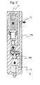
- Fig. 2 is a cross-sectional view of the fuel injection valve 9 used in the diesel engine 1 shown in Fig. 1.
- the fuel injection valve 9 has a piezoelectric actuator 11, and a needle valve 12.
- the piezoelectric actuator 11 has multiple piezoelectric elements, which are laminated in a cylindrical valve body 19a of the fuel injection valve 9.
- the needle valve 12 is driven by the piezoelectric actuator 11.
- a control room 19b is provided in the valve body 19a.
- the piezoelectric actuator 11 is connected to the first EDU 6a or the second EDU 6b, and receives driving electricity therefrom.
- highly pressurized fuel is supplied to the valve body 19a from the common rail 10.
- the piezoelectric actuator 11 is driven, the pressure balance within the valve body 19a is changed so as to slide the needle valve 12 so that the fuel injection valve 9 can be opened or closed.
- the fuel injection valve 9 may be replaced with another type of fuel injection valve.
- another type of actuator may be used for the piezoelectric type.
- the driver of the vehicle operates the brakes 3 and the brake switch 3b is turned on.
- the ECU 2 refers to data supplied from the vehicle speed sensor 4 and determines whether the vehicle stops. When it is determined that the vehicle stops, the ECU 2 executes the automatic engine stop program stored in the ROM 2a in the ECU 2, and stops issuance of commands for fuel injection to the first and second EDUs 6a and 6b. Thus, fuel injection by the fuel injection valves 9a through 9d is stopped so that the diesel engine 1 stops operating.
- the common rail pressure is applied to the control room 19b of the fuel injection valve 9, and the tip end of the needle valve 12 is pressed against the end of the valve body 19a.
- the needle valve 12 continuously receives the high common rail pressure and is gradually deformed elastically.
- the generator does not work, and the first and second EDUs 6a and 6b continuously discharge the charges stored therein, and fall short of charges.
- the ECU 2 determines, at step S11, whether the engine restart instruction is issued, that is, whether the brake switch 3b is turned off. When the answer of step S11 is NO, the ECU 2 executes step S11 again. The ECU 2 executes step S11 repeatedly until the restart instruction is issued.
- step S12 estimates the amount or degree of elastic deformation of the needle valves 12 by referring to the time or period during which the engine 1 is in the stopped state and referring to the common rail pressure. It is not essential to execute step S12 after the answer of step S11 becomes YES but is possible to execute step S12 at an appropriate timing.
- the amount of elastic deformation of the needle valves 12 may be periodically estimated after the program shown in Fig. 3 is initiated.
- the amount of elastic deformation of the needle valves 12 is estimated by referring to both the engine stopping period before the diesel engine 1 is restarted and the common rail pressure. Alternatively, either one of the engine stopping period and the common rail pressure may be referred to in order to estimate the amount of elastic deformation of the needle valves 12.
- step S13 the ECU 2 computes the time it takes to restore the needle valves 12 from the elastically deformed state on the basis of the estimated amount of elastic deformation thereof, and sets the computed time as a pseudo-injection time.
- the pseudo-injection time fuel is not injected through the fuel injection valves 9a through 9d.
- the ECU 2 supplies the first and second EDUs 6a and 6b with a pseudo-injection instruction to the fuel injection valves 9a through 9d.
- the EDUs 6a and 6b are charged and the needle valves 12 are simultaneously restored from the elastically deformed state.
- the first and second EDUs 6a and 6b are charged while the needle valves 12 are restored from the elastically deformed state. Then, as step S15, the ECU 2 issues the starter driving instruction. The starter 7 is thus driven, and the diesel engine 1 is restarted.
- the first and second EDUs 6a and 6b are charged and the needle valves 12 are simultaneously restored from the elastically deformed state prior to driving the starter 7. It is thus possible to avoid the delay in injection of fuel in the first fuel injection cycle after the starter 7 is driven and to restart the diesel engine 1 quickly and reliably in the first fuel injection cycle. The driver does not feel stress and starts the vehicle smoothly.
- a description will now be given, with reference to Figs. 4 and 5, of a second embodiment of the present invention.
- the first and second EDUs 6a and 6b are charged and the needle valves 12 are restored from the elastically deformed state.
- the second embodiment charges the first and second EDUs 6a and 6b and restores the needle valves 12 from the elastically deformed state after the starter 7 starts to operate.
- the diesel engine of the second embodiment has the same structure as shown in Fig. 1 except the content of the injection accelerating control program stored in the ROM 2a.
- Step S21 the ECU 2 estimates, at step S21, the amount or degree of elastic deformation of the needle valves 12 by referring to the time during which the engine 1 is in the stopped state and referring to the common rail pressure.
- Step 21 is the same as step S12 shown in Fig. 3.
- step S22 determines whether the engine restart instruction is issued, that is, whether the brake switch 3b is turned off.
- the process returns to step S21.
- the ECU 2 executes step S21 repeatedly until the engine restart instruction is issued.
- the ECU 2 accurately estimates the amount of elastic deformation of the valves 12 that may vary with time.
- step S23 the ECU 2 issues the instruction to drive the starter 7, and simultaneously issues an instruction to drive the first and second EDUs 6a and 6b for a minimum time ⁇ .
- the minimum time ⁇ corresponds to the pulse width of the drive signal applied to the first and second EDUs 6a and 6b and minimally needed to set the first and second EDUs 6a and 6b to the charged state.
- the minimum time ⁇ may, for example, be 50 ⁇ s.
- the instruction to drive the starter 7 for the minimum time ⁇ is issued before fuel is actually injected, as shown in Fig. 5.
- the first and second EDUs 6a and 6b can store the charges enough to drive the piezoelectric actuators 11 of the fuel injection valves 9 without any delay in response.
- the ECU 2 computes an invalid injection period from the estimated amount of elastic deformation of the needle valves 12 obtained at step S21.
- the ECU 2 computes an advance-angle correction amount To corresponding to the invalid injection period obtained at step S24.
- step S26 the ECU 2 computes a corrected fuel injection period ⁇ 1 of the first-time fuel injection cycle by adding the advance-angle correction amount ⁇ o to the regular injection period ⁇ , and starts fuel injection with the corrected fuel injection period ⁇ 1 thus computed.
- the needle valves 12 can be restored from the elastically deformed state within the advance-angle correction amount ⁇ o after the injection instruction is issued. It is thus possible to secure the enough amount of fuel to be injected in the first injection cycle without any delay in the time of opening the valves 12.
- step S27 the ECU 2 executes the normal starting control with the regular fuel injection period ⁇ from the second fuel injection cycle.
- the third embodiment differs from the second embodiment in that the third embodiment employs a more fine control for each cylinder.
- Steps S31 and S32 are respectively the same as steps S21 and S22 of the second embodiment shown in Fig. 4, and a description thereof is thus omitted.
- step S32 When the answer of step S32 is YES, the ECU 2 issues the drive instruction to the starter 7 at step S33.
- the ECU 2 determines whether each cylinder is about to enter into the first fuel injection cycle.
- the four cylinders of the four-cylinder diesel engine 1 shown in Fig. 1 sequentially have the ignition timings.
- the injection accelerating control is performed in order to make ready for the first fuel injection cycle so that the first and second EDUs 6a and 6b can be charged and the needle valves 12 can be restored from the elastically deformed state.
- step S34 When the answer of step S34 is NO, that is, when each cylinder does not have the first fuel injection cycle, the process proceeds to step S39 at which the ECU 2 determines whether the injection accelerating control for each cylinder is completed. When the answer of step S39 is NO, the process returns to step S34, and the above mentioned process is repeatedly carried out.
- step S34 When the answer of step S34 is YES, that is, when the cylinder of interest is about to enter into the first fuel injection cycle, the ECU 2 sequentially executes steps S35 to S38, which are respectively the same as steps 23 to S26 of the second embodiment shown in Fig. 3 except step S23 at which the driving instruction to the starter 7 is issued. More specifically, at step S35, the ECU 2 issues the instruction to drive the starter 7, and simultaneously issues the instruction to drive the first and second EDUs 6a and 6b for the minimum time ⁇ . At step S36, the ECU 2 computes the invalid injection period from the estimated amount of elastic deformation of the needle valves 12 obtained at step S31.
- the ECU 2 computes the advance-angle correction amount ⁇ o corresponding to the invalid injection period obtained at step S36.
- the ECU 2 computes the corrected fuel injection period ⁇ 1 of the first-time fuel injection cycle by adding the advance-angle correction amount ⁇ o to the regular injection period ⁇ , and starts fuel injection with the corrected fuel injection period ⁇ 1 thus computed.
- step S39 the ECU 2 determines whether the injection accelerating control for each cylinder is completed.
- the ECU 2 executes the normal starting control with the regular fuel injection period ⁇ from the second fuel injection cycle at step S40.
- step S39 is NO, the process of the ECU 2 returns to step S34.
- the fuel accelerating control program may be modified so that the steps thereof are executed in a sequence different from the aforementioned sequences as long as the delay in injection in the first fuel injection cycle can be avoided.
Landscapes
- Engineering & Computer Science (AREA)
- Chemical & Material Sciences (AREA)
- Combustion & Propulsion (AREA)
- Mechanical Engineering (AREA)
- General Engineering & Computer Science (AREA)
- Electrical Control Of Air Or Fuel Supplied To Internal-Combustion Engine (AREA)
- Control Of Vehicle Engines Or Engines For Specific Uses (AREA)
- Output Control And Ontrol Of Special Type Engine (AREA)
- Combined Controls Of Internal Combustion Engines (AREA)
Abstract
Description
- The present invention relates to fuel injection systems, and more particularly, to a fuel injection system for a common rail type diesel engine having an automatic engine stop/start control.
- An internal combustion engine for vehicles having the idle stop function is known. This function automatically stops the engine when the vehicle stops at an intersection or the like to thus improve fuel economy. When an operation to start the vehicle is performed, the starter is activated to automatically start the engine so that the vehicle is ready to start. A system that implements the automatic engine stop/start control is disclosed in, for example, Japanese Patent Application Publication No. 2000-337188 or 2003-41967.
- The automatic engine start/stop control system may be incorporated into the diesel engine for vehicles. When the system is applied to the common rail type diesel engine, the following problems occur.
- The common rail type diesel engine is equipped with a fuel injection valve in which highly pressurized fuel prepared by the common rail is filled in a cylindrical valve body having a needle valve provided in the cylindrical valve body and driven by an actuator. It takes a considerable long time to restart the diesel engine due to a delay in the response of the needle valve.
- The following factor may cause the delay in the response of the needle valve. First, an EDU (Electric Driver Unit) for driving the actuator may fall short of charge. The EDU is a unit specifically designed to drive an injector or spindle valve at high fuel pressure and high speed by a high-voltage, rapid charge system using a DC/DC converter. Normally, the injector or the like is directly driven by an engine computer. In contrast, in a direct-injection system, the EDU receives an injection signal from the engine computer and drives the injector or the spindle valve at high speed with a boosted voltage of 100 V or higher available in the EDU. It is thus possible to precisely regulate the air-fuel ratio. The performance of the injector driver is always monitored by the engine computer. If a fault takes place in the driver system, the engine computer executes a fail-safe sequence by, for example, cutting fuel injection for a cylinder related to the fault, and turns on an engine check indicator. When the automatic engine start/stop control system automatically stops the engine, electricity is no longer generated, so that the EDU cannot be charged any more. During the time when the diesel engine stops, the charge stored in the EDU is naturally discharged. The EDU that has fallen short of charge cannot drive the needle valve adequately in response to the injection instruction when the engine is restarted, and fuel is not injected appropriately.
- Second, the needle valve in the cylindrical valve body may be deformed elastically so as to be pressed against the inner wall of the valve body because it receives high pressure produced by the common rail. This problem occurs during the time when the engine remains stopped by the automatic engine start/stop control system. In the normal injection, the needle valve is detached from the valve body only a short time that is not enough to cause elastic deformation. In contrast, when the diesel engine is stopped, the needle valve receives high common rail pressure and is elastically deformed. Usually, the engine is automatically restarted only a short time by the automatic engine stop/start control system after the engine is automatically stopped. Thus, when the engine is restarted, the high common rail pressure remains in the valve body of the fuel injection valve and the needle valve is in the elastically deformed state. It takes a certain time for the needle valve to be restored from the elastically deformed state when it is driven by the actuator at the time of restarting. Thus, the fuel injection valve opens with the delay necessary for the recovery from the elastic deformation. Usually, the above-mentioned problem does not occur when the driver intentionally turned off the ignition switch and turns it on again to start the diesel engine again.
- The delay in the fuel injection may not bring about appropriate ignition in the first cycle (the first compression stroke) after the engine is restarted. Thus, ignition in the involved cylinder does not occur until the next compression stroke. This delays the engine restarting. The relay in restarting the engine may cause a delay in starting the vehicle.
- The present invention has been made in view of the above-mentioned circumstances and provides a fuel injection system capable of realizing appropriate ignition in the first cycle after the engine is restarted and restarting the engine quickly and stably.
- According to an aspect of the present invention, there is provided a fuel injection system for a common rail type diesel engine having an automatic engine stop/start control, characterized by comprising a controller that executes an injection accelerating control to avoid a delay in injection of a first fuel injection cycle after the diesel engine is automatically restarted.
- According to another aspect of the present invention, there is provided a diesel engine equipped with the above-mentioned fuel injection system.
- According to a further aspect of the present invention, there is provided a method of controlling a fuel injection for a common rail type diesel engine including a step of determining whether the diesel engine should be automatically restarted, characterized in that the method further comprises a step of executing an injection accelerating control to avoid a delay in injection of a first fuel injection cycle after the diesel engine is automatically restarted when it is determined that the diesel engine should be automatically restarted.
- Other objects, features and advantages of the present invention will become more apparent from the following detailed description when read in conjunction with the following drawings, in which:
- Fig. 1 is a block diagram of a diesel engine in accordance with an embodiment of the present invention;
- Fig. 2 is a cross-sectional view of a fuel injection valve employed in the diesel engine shown in Fig. 1;
- Fig. 3 is a flow chart of an injection accelerating control program in accordance with a first embodiment of the present invention;
- Fig. 4 is a flowchart of an injection accelerating control program in accordance with a second embodiment of the present invention;
- Fig. 5 is a waveform diagram of a fuel injection instruction used in the second embodiment; and
- Fig. 6 is a flowchart of an injection accelerating control program in accordance with a third embodiment of the present invention.
- A description will now be given, with reference to the accompanying drawings, of embodiments of the present invention.
- Fig. 1 shows a
diesel engine 1 equipped with a fuel injection system in accordance with an embodiment of the present invention. Thediesel engine 1 is equipped with an ECU (Electronic Control Unit) 2, which functions as a controller of thediesel engine 1 and handles various controls. The ECU 2 is connected to a brake switch 3b interlocked with a brake pedal 3a, avehicle speed sensor 4, a starter 5, a first EDU 6a, and a second EDU 6b. The ECU 2 includes a microcomputer as a main component, and a ROM 2a, which stores an automatic engine stop program, and an automatic engine start program in order to perform the automatic engine start/stop control of thediesel engine 1. Further, the ROM 2a stores an injection accelerating control program for the purpose of avoiding the delay in injection in the first fuel injection after thediesel engine 1 is automatically restarted. - The
diesel engine 1 shown in Fig. 4 has four cylinders respectively provided with four fuel injection valves (INJ) 9 attached to anengine body 8. The fourfuel injection valves 9 are a first fuel injection valve 9a, a second fuel injection valve 9b, a third fuel injection valve 9c and a fourth fuel injection valve 9d. A common rail 10 is connected to the four fuel injection valves 9a through 9d, and supplies highly pressurized fuel thereto. The first and second fuel injection valves 9a and 9b are connected to the first EDU 6a, and the third and fourth fuel injection valves 9c and 9d are connected to the second EDU 6b. - Fig. 2 is a cross-sectional view of the
fuel injection valve 9 used in thediesel engine 1 shown in Fig. 1. Thefuel injection valve 9 has apiezoelectric actuator 11, and a needle valve 12. Thepiezoelectric actuator 11 has multiple piezoelectric elements, which are laminated in acylindrical valve body 19a of thefuel injection valve 9. The needle valve 12 is driven by thepiezoelectric actuator 11. Acontrol room 19b is provided in thevalve body 19a. Thepiezoelectric actuator 11 is connected to the first EDU 6a or the second EDU 6b, and receives driving electricity therefrom. As indicated by anarrow 13, highly pressurized fuel is supplied to thevalve body 19a from the common rail 10. When thepiezoelectric actuator 11 is driven, the pressure balance within thevalve body 19a is changed so as to slide the needle valve 12 so that thefuel injection valve 9 can be opened or closed. - The
fuel injection valve 9 may be replaced with another type of fuel injection valve. For example, another type of actuator may be used for the piezoelectric type. - A description will now be given of an operation of the
diesel engine 1. In the following, it is assumed that thediesel engine 1 is installed in a vehicle equipped with an automatic transmission. - The driver of the vehicle operates the
brakes 3 and the brake switch 3b is turned on. TheECU 2 refers to data supplied from thevehicle speed sensor 4 and determines whether the vehicle stops. When it is determined that the vehicle stops, theECU 2 executes the automatic engine stop program stored in the ROM 2a in theECU 2, and stops issuance of commands for fuel injection to the first and second EDUs 6a and 6b. Thus, fuel injection by the fuel injection valves 9a through 9d is stopped so that thediesel engine 1 stops operating. - Even when the
engine 1 is in the stopped state, the common rail pressure is applied to thecontrol room 19b of thefuel injection valve 9, and the tip end of the needle valve 12 is pressed against the end of thevalve body 19a. During the time when thediesel engine 1 is stopping, the needle valve 12 continuously receives the high common rail pressure and is gradually deformed elastically. In the engine stopped state, the generator does not work, and the first and second EDUs 6a and 6b continuously discharge the charges stored therein, and fall short of charges. - When the
brake pedal 3 is released under the condition that the engine is in the stopped state, the brake switch 3b is turned off, and theECU 2 start to execute the automatic engine start program stored in the ROM 2a. Then, theECU 2 drives thestarter 7, so that thediesel engine 1 can be automatically restarted. Simultaneously, theECU 2 starts to execute the fuel accelerating control program stored in the ROM 2a and performs a starter driving control (step S15 in Fig. 3) described in the program. A description will now be given, with reference to the flowchart of Fig. 3, of a control based on the injection accelerating control program in accordance with a first embodiment of the present invention. - First, the
ECU 2 determines, at step S11, whether the engine restart instruction is issued, that is, whether the brake switch 3b is turned off. When the answer of step S11 is NO, theECU 2 executes step S11 again. TheECU 2 executes step S11 repeatedly until the restart instruction is issued. - When the answer of step S11 becomes YES, the
ECU 2 proceeds to step S12 and estimates the amount or degree of elastic deformation of the needle valves 12 by referring to the time or period during which theengine 1 is in the stopped state and referring to the common rail pressure. It is not essential to execute step S12 after the answer of step S11 becomes YES but is possible to execute step S12 at an appropriate timing. For example, the amount of elastic deformation of the needle valves 12 may be periodically estimated after the program shown in Fig. 3 is initiated. Preferably, the amount of elastic deformation of the needle valves 12 is estimated by referring to both the engine stopping period before thediesel engine 1 is restarted and the common rail pressure. Alternatively, either one of the engine stopping period and the common rail pressure may be referred to in order to estimate the amount of elastic deformation of the needle valves 12. - At step S13 subsequent to step S12, the
ECU 2 computes the time it takes to restore the needle valves 12 from the elastically deformed state on the basis of the estimated amount of elastic deformation thereof, and sets the computed time as a pseudo-injection time. During the pseudo-injection time, fuel is not injected through the fuel injection valves 9a through 9d. - At step S 14, the
ECU 2 supplies the first and second EDUs 6a and 6b with a pseudo-injection instruction to the fuel injection valves 9a through 9d. In response to the instruction, the EDUs 6a and 6b are charged and the needle valves 12 are simultaneously restored from the elastically deformed state. - In the above-mentioned sequence, the first and second EDUs 6a and 6b are charged while the needle valves 12 are restored from the elastically deformed state. Then, as step S15, the
ECU 2 issues the starter driving instruction. Thestarter 7 is thus driven, and thediesel engine 1 is restarted. - As described above, according to the present invention, the first and second EDUs 6a and 6b are charged and the needle valves 12 are simultaneously restored from the elastically deformed state prior to driving the
starter 7. It is thus possible to avoid the delay in injection of fuel in the first fuel injection cycle after thestarter 7 is driven and to restart thediesel engine 1 quickly and reliably in the first fuel injection cycle. The driver does not feel stress and starts the vehicle smoothly. - A description will now be given, with reference to Figs. 4 and 5, of a second embodiment of the present invention. In the above-mentioned first embodiment, prior to driving the
starter 7, the first and second EDUs 6a and 6b are charged and the needle valves 12 are restored from the elastically deformed state. In contrast, the second embodiment charges the first and second EDUs 6a and 6b and restores the needle valves 12 from the elastically deformed state after thestarter 7 starts to operate. The diesel engine of the second embodiment has the same structure as shown in Fig. 1 except the content of the injection accelerating control program stored in the ROM 2a. - When the
diesel engine 1 stops, theECU 2 estimates, at step S21, the amount or degree of elastic deformation of the needle valves 12 by referring to the time during which theengine 1 is in the stopped state and referring to the common rail pressure. Step 21 is the same as step S12 shown in Fig. 3. - Then, the
ECU 2 proceeds to step S22, and determines whether the engine restart instruction is issued, that is, whether the brake switch 3b is turned off. When the answer of Step S22 is NO, the process returns to step S21. TheECU 2 executes step S21 repeatedly until the engine restart instruction is issued. TheECU 2 accurately estimates the amount of elastic deformation of the valves 12 that may vary with time. - When the answer of step S22 becomes YES, the process proceeds to step S23 at which the
ECU 2 issues the instruction to drive thestarter 7, and simultaneously issues an instruction to drive the first and second EDUs 6a and 6b for a minimum time τα. The minimum time τα corresponds to the pulse width of the drive signal applied to the first and second EDUs 6a and 6b and minimally needed to set the first and second EDUs 6a and 6b to the charged state. The minimum time τα may, for example, be 50 µs. The instruction to drive thestarter 7 for the minimum time τα is issued before fuel is actually injected, as shown in Fig. 5. Thus, the first and second EDUs 6a and 6b can store the charges enough to drive thepiezoelectric actuators 11 of thefuel injection valves 9 without any delay in response. - At step S24, the
ECU 2 computes an invalid injection period from the estimated amount of elastic deformation of the needle valves 12 obtained at step S21. At step S25, theECU 2 computes an advance-angle correction amount To corresponding to the invalid injection period obtained at step S24. - At step S26 subsequent to step S25, the
ECU 2 computes a corrected fuel injection period τ1 of the first-time fuel injection cycle by adding the advance-angle correction amount τo to the regular injection period τ, and starts fuel injection with the corrected fuel injection period τ1 thus computed. With this structure, the needle valves 12 can be restored from the elastically deformed state within the advance-angle correction amount τo after the injection instruction is issued. It is thus possible to secure the enough amount of fuel to be injected in the first injection cycle without any delay in the time of opening the valves 12. - Then, the process proceeds to step S27 at which the
ECU 2 executes the normal starting control with the regular fuel injection period τ from the second fuel injection cycle. - It is thus possible to start the
diesel engine 1 quickly and reliably. - A description will now be given, with reference to Fig. 6, of a third embodiment of the present invention. The third embodiment differs from the second embodiment in that the third embodiment employs a more fine control for each cylinder.
- Steps S31 and S32 are respectively the same as steps S21 and S22 of the second embodiment shown in Fig. 4, and a description thereof is thus omitted.
- When the answer of step S32 is YES, the
ECU 2 issues the drive instruction to thestarter 7 at step S33. - At step S34, the
ECU 2 determines whether each cylinder is about to enter into the first fuel injection cycle. The four cylinders of the four-cylinder diesel engine 1 shown in Fig. 1 sequentially have the ignition timings. In each of the cylinders, the injection accelerating control is performed in order to make ready for the first fuel injection cycle so that the first and second EDUs 6a and 6b can be charged and the needle valves 12 can be restored from the elastically deformed state. - When the answer of step S34 is NO, that is, when each cylinder does not have the first fuel injection cycle, the process proceeds to step S39 at which the
ECU 2 determines whether the injection accelerating control for each cylinder is completed. When the answer of step S39 is NO, the process returns to step S34, and the above mentioned process is repeatedly carried out. - When the answer of step S34 is YES, that is, when the cylinder of interest is about to enter into the first fuel injection cycle, the
ECU 2 sequentially executes steps S35 to S38, which are respectively the same as steps 23 to S26 of the second embodiment shown in Fig. 3 except step S23 at which the driving instruction to thestarter 7 is issued. More specifically, at step S35, theECU 2 issues the instruction to drive thestarter 7, and simultaneously issues the instruction to drive the first and second EDUs 6a and 6b for the minimum time τα. At step S36, theECU 2 computes the invalid injection period from the estimated amount of elastic deformation of the needle valves 12 obtained at step S31. At step S37, theECU 2 computes the advance-angle correction amount τo corresponding to the invalid injection period obtained at step S36. At step S38, theECU 2 computes the corrected fuel injection period τ1 of the first-time fuel injection cycle by adding the advance-angle correction amount τo to the regular injection period τ, and starts fuel injection with the corrected fuel injection period τ1 thus computed. - At step S39, the
ECU 2 determines whether the injection accelerating control for each cylinder is completed. When the answer of step S39 is YES, theECU 2 executes the normal starting control with the regular fuel injection period τ from the second fuel injection cycle at step S40. When the answer of step S39 is NO, the process of theECU 2 returns to step S34. - It is thus possible to start the
diesel engine 1 quickly and reliably. - The present invention is not limited to the specifically disclosed embodiments, but various embodiments, variations and modifications may be made without departing from the scope of the present invention. For example, the fuel accelerating control program may be modified so that the steps thereof are executed in a sequence different from the aforementioned sequences as long as the delay in injection in the first fuel injection cycle can be avoided.
Claims (18)
- A fuel injection system for a common rail type diesel engine having an automatic engine stop/start control, characterized by comprising a controller that executes an injection accelerating control to avoid a delay in injection of a first fuel injection cycle after the diesel engine is automatically restarted.
- The fuel injection system as claimed in claim 1, characterized in that the controller issues a pseudo-injection instruction that drives a needle valve of a fuel injection valve without actually injecting fuel thereto.
- The fuel injection system as claimed in claim 1, characterized in that the controller issues a pseudo-injection instruction that drives a needle valve of a fuel injection valve without actually injecting fuel thereto via an EDU (Electric Drive Unit), which is charged in response to the pseudo-injection instruction.
- The fuel injection system as claimed in claim 1, characterized in that the controller issues an injection instruction that drives a needle for a longer fuel injection period in the first fuel injection cycle than that in a fuel injection cycle following the first fuel injection cycle.
- The fuel injection system as claimed in claim 1, characterized in that the controller issues an injection instruction that drives a needle in the first fuel injection cycle at an advance-angle timing.
- The fuel injection system as claimed in claim 1, characterized in that the controller issues a pseudo-injection instruction that charges an EDU (Electric Drive Unit) prior to the first fuel injection cycle, and issues a fuel injection instruction that drives a needle valve of a fuel injection valve via the EDU in the first fuel injection cycle.
- The fuel injection system as claimed in claim 6, characterized in that the controller issues the fuel injection instruction for the first fuel injection cycle at an advance-angle timing as compared to a regular fuel injection timing.
- The fuel injection system as claimed in claim 1, characterized in that the controller computes an amount of elastic deformation of a needle valve of a fuel injection valve by referring to an engine stopping time before the diesel engine is restarted, and the controller executes the injection accelerating control based on the amount of elastic deformation of the needle valve.
- The fuel injection system as claimed in claim 1, characterized in that the controller refers to a common rail pressure and executes the injection accelerating control based on the common rail pressure.
- The fuel injection system as claimed in claim 1, characterized in that the controller computes an amount of elastic deformation of a needle valve of a fuel injection valve by referring to an engine stopping time before the diesel engine is restarted and a common rail pressure, and the controller executes the injection accelerating control based on the amount of elastic deformation of the needle valve and the common rail pressure.
- The fuel injection system as claimed in claim 1, characterized in that the controller computes a fuel injection timing in the first fuel injection cycle after the diesel engine is restarted before the controller issues a starter driving instruction in order to restart the diesel engine.
- The fuel injection system as claimed in claim 1, characterized in that the controller computes a fuel injection timing in the first fuel injection cycle after the diesel engine is restarted after the controller issues a starter driving instruction in order to restart the diesel engine.
- A diesel engine comprising a fuel injection system as claimed in any of claims 1 to 12.
- A method of controlling a fuel injection for a common rail type diesel engine including a step of determining whether the diesel engine should be automatically restarted, characterized in that the method further comprises a step of executing an injection accelerating control to avoid a delay in injection of a first fuel injection cycle after the diesel engine is automatically restarted when it is determined that the diesel engine should be automatically restarted.
- The method as claimed in claim 14, characterized by further comprising a step of issuing a pseudo-injection that drives a needle valve of a fuel injection valve without actually injecting fuel thereto.
- The method as claimed in claim 14, characterized by further comprising a step of issuing an injection instruction that drives a needle for a longer fuel injection period in the first fuel injection cycle than that in a fuel injection cycle following the first fuel injection cycle.
- The method as claimed in claim 14, characterized by further comprising a step of issuing an injection instruction that drives a needle in the first fuel injection cycle at an advance-angle timing.
- The method as claimed in claim 14, characterized by further comprising the steps of:estimating an amount of elastic deformation of a needle valve of a fuel injection valve by referring to at least one of an engine stopping time before the diesel engine is restarted and a common rail pressure; andexecuting the injection accelerating control based on said at least one of the amount of elastic deformation of the needle valve and the common rail pressure.
Applications Claiming Priority (1)
| Application Number | Priority Date | Filing Date | Title |
|---|---|---|---|
| JP2005008878A JP4363331B2 (en) | 2005-01-17 | 2005-01-17 | Fuel injection system |
Publications (3)
| Publication Number | Publication Date |
|---|---|
| EP1681450A2 true EP1681450A2 (en) | 2006-07-19 |
| EP1681450A3 EP1681450A3 (en) | 2006-11-08 |
| EP1681450B1 EP1681450B1 (en) | 2009-05-13 |
Family
ID=36123136
Family Applications (1)
| Application Number | Title | Priority Date | Filing Date |
|---|---|---|---|
| EP06000840A Expired - Lifetime EP1681450B1 (en) | 2005-01-17 | 2006-01-16 | Fuel injection system |
Country Status (4)
| Country | Link |
|---|---|
| EP (1) | EP1681450B1 (en) |
| JP (1) | JP4363331B2 (en) |
| DE (1) | DE602006006728D1 (en) |
| ES (1) | ES2323798T3 (en) |
Cited By (1)
| Publication number | Priority date | Publication date | Assignee | Title |
|---|---|---|---|---|
| US9273583B2 (en) | 2009-12-21 | 2016-03-01 | Johnson Matthey Public Limited Company | Exhaust system for a vehicle having a “stop-start” compression ignition engine |
Citations (2)
| Publication number | Priority date | Publication date | Assignee | Title |
|---|---|---|---|---|
| JP2000337188A (en) | 1999-05-27 | 2000-12-05 | Toyota Motor Corp | Automatic stop / start device for internal combustion engine |
| JP2003041967A (en) | 2001-07-26 | 2003-02-13 | Toyota Motor Corp | Automatic stop control device for internal combustion engine |
Family Cites Families (7)
| Publication number | Priority date | Publication date | Assignee | Title |
|---|---|---|---|---|
| DE19945670B4 (en) * | 1999-09-23 | 2006-01-12 | Siemens Ag | Method for driving a capacitive actuator of a fuel injection valve of an internal combustion engine |
| EP1138909B1 (en) * | 2000-04-01 | 2005-09-21 | Robert Bosch GmbH | Method and apparatus for controlling a fuel injection process |
| DE10032022B4 (en) * | 2000-07-01 | 2009-12-24 | Robert Bosch Gmbh | Method for determining the drive voltage for an injection valve with a piezoelectric actuator |
| DE10228063A1 (en) * | 2002-06-17 | 2004-01-08 | Robert Bosch Gmbh | Method for operating an internal combustion engine, in particular a motor vehicle |
| JP4161635B2 (en) * | 2002-08-19 | 2008-10-08 | 株式会社デンソー | Fuel injection control device |
| DE10249218A1 (en) * | 2002-10-22 | 2004-05-19 | Siemens Ag | Method for charging a piezoelectric actuator of an injection valve and control device |
| DE10303573B4 (en) * | 2003-01-30 | 2011-02-24 | Robert Bosch Gmbh | Method, computer program, storage medium and control and / or regulating device for operating an internal combustion engine, and internal combustion engine, in particular for a motor vehicle |
-
2005
- 2005-01-17 JP JP2005008878A patent/JP4363331B2/en not_active Expired - Fee Related
-
2006
- 2006-01-16 ES ES06000840T patent/ES2323798T3/en not_active Expired - Lifetime
- 2006-01-16 DE DE602006006728T patent/DE602006006728D1/en not_active Expired - Lifetime
- 2006-01-16 EP EP06000840A patent/EP1681450B1/en not_active Expired - Lifetime
Patent Citations (2)
| Publication number | Priority date | Publication date | Assignee | Title |
|---|---|---|---|---|
| JP2000337188A (en) | 1999-05-27 | 2000-12-05 | Toyota Motor Corp | Automatic stop / start device for internal combustion engine |
| JP2003041967A (en) | 2001-07-26 | 2003-02-13 | Toyota Motor Corp | Automatic stop control device for internal combustion engine |
Cited By (2)
| Publication number | Priority date | Publication date | Assignee | Title |
|---|---|---|---|---|
| US9273583B2 (en) | 2009-12-21 | 2016-03-01 | Johnson Matthey Public Limited Company | Exhaust system for a vehicle having a “stop-start” compression ignition engine |
| EP2516812B1 (en) * | 2009-12-21 | 2018-10-10 | Johnson Matthey Public Limited Company | Exhaust system for a vehicle having a "stop- start" compression ignition engine |
Also Published As
| Publication number | Publication date |
|---|---|
| EP1681450A3 (en) | 2006-11-08 |
| JP4363331B2 (en) | 2009-11-11 |
| ES2323798T3 (en) | 2009-07-24 |
| JP2006194214A (en) | 2006-07-27 |
| EP1681450B1 (en) | 2009-05-13 |
| DE602006006728D1 (en) | 2009-06-25 |
Similar Documents
| Publication | Publication Date | Title |
|---|---|---|
| US7278405B2 (en) | Fuel injection system designed to ensure enhanced reliability of diagnosis of valve | |
| EP1918558B1 (en) | Fuel injection controller and diagnosis method of fuel supply system | |
| US7891339B2 (en) | Control apparatus capable of suitably controlling fuel injection apparatus regardless of variation in fuel pressure in accumulator | |
| AU751190B2 (en) | Method for enhanced split injection in internal combustion engines | |
| US8011351B2 (en) | Method for driving solenoid-actuated fuel injectors of internal combustion engines | |
| US7316220B2 (en) | Actuator drive system and fuel injection system | |
| US20130206111A1 (en) | Method and Device for Operating a High-Pressure Accumulator Fuel Injection System for an Internal Combustion Engine | |
| US9086028B2 (en) | Method and device for operating an injection valve | |
| CN101498264A (en) | Fuel injector for internal combustion engine | |
| US20070079811A1 (en) | Fuel injection controller of diesel engine | |
| US20130298875A1 (en) | Method for operating a motor vehicle | |
| JP5278472B2 (en) | Abnormality diagnosis device for fuel injection valve | |
| JP4685638B2 (en) | Fuel injection amount control device and internal combustion engine equipped with the control device | |
| US20100186718A1 (en) | Method for operating an injector | |
| JP2003161233A (en) | Method of determining fuel injector performance in chassis and electronic control module applying the same | |
| EP1681450B1 (en) | Fuel injection system | |
| JP2000248983A (en) | Fuel pressure control device for high pressure fuel injection system | |
| KR101865913B1 (en) | A fuel injection control method for variable cylinder-deactivation engine | |
| JP2019082150A (en) | Control device of fuel injection valve and control method of fuel injection valve | |
| JP4737227B2 (en) | Fuel injection amount control device | |
| US12338778B2 (en) | Method of operating a fuel injection system | |
| US20250154922A1 (en) | Gaseous injector preparation method for cold engine start | |
| JP2002242740A (en) | Fuel injection device | |
| JP2019039323A (en) | Fuel injection control device | |
| CN118900950A (en) | Method of controlling fuel injection |
Legal Events
| Date | Code | Title | Description |
|---|---|---|---|
| PUAI | Public reference made under article 153(3) epc to a published international application that has entered the european phase |
Free format text: ORIGINAL CODE: 0009012 |
|
| 17P | Request for examination filed |
Effective date: 20060116 |
|
| AK | Designated contracting states |
Kind code of ref document: A2 Designated state(s): AT BE BG CH CY CZ DE DK EE ES FI FR GB GR HU IE IS IT LI LT LU LV MC NL PL PT RO SE SI SK TR |
|
| AX | Request for extension of the european patent |
Extension state: AL BA HR MK YU |
|
| PUAL | Search report despatched |
Free format text: ORIGINAL CODE: 0009013 |
|
| AK | Designated contracting states |
Kind code of ref document: A3 Designated state(s): AT BE BG CH CY CZ DE DK EE ES FI FR GB GR HU IE IS IT LI LT LU LV MC NL PL PT RO SE SI SK TR |
|
| AX | Request for extension of the european patent |
Extension state: AL BA HR MK YU |
|
| 17Q | First examination report despatched |
Effective date: 20070514 |
|
| AKX | Designation fees paid |
Designated state(s): DE ES FR GB IT |
|
| GRAP | Despatch of communication of intention to grant a patent |
Free format text: ORIGINAL CODE: EPIDOSNIGR1 |
|
| GRAS | Grant fee paid |
Free format text: ORIGINAL CODE: EPIDOSNIGR3 |
|
| GRAA | (expected) grant |
Free format text: ORIGINAL CODE: 0009210 |
|
| AK | Designated contracting states |
Kind code of ref document: B1 Designated state(s): DE ES FR GB IT |
|
| REG | Reference to a national code |
Ref country code: GB Ref legal event code: FG4D |
|
| REF | Corresponds to: |
Ref document number: 602006006728 Country of ref document: DE Date of ref document: 20090625 Kind code of ref document: P |
|
| REG | Reference to a national code |
Ref country code: ES Ref legal event code: FG2A Ref document number: 2323798 Country of ref document: ES Kind code of ref document: T3 |
|
| PLBE | No opposition filed within time limit |
Free format text: ORIGINAL CODE: 0009261 |
|
| STAA | Information on the status of an ep patent application or granted ep patent |
Free format text: STATUS: NO OPPOSITION FILED WITHIN TIME LIMIT |
|
| 26N | No opposition filed |
Effective date: 20100216 |
|
| REG | Reference to a national code |
Ref country code: GB Ref legal event code: 746 Effective date: 20121012 |
|
| REG | Reference to a national code |
Ref country code: DE Ref legal event code: R084 Ref document number: 602006006728 Country of ref document: DE Effective date: 20121015 |
|
| REG | Reference to a national code |
Ref country code: FR Ref legal event code: PLFP Year of fee payment: 11 |
|
| REG | Reference to a national code |
Ref country code: FR Ref legal event code: PLFP Year of fee payment: 12 |
|
| PGFP | Annual fee paid to national office [announced via postgrant information from national office to epo] |
Ref country code: ES Payment date: 20161213 Year of fee payment: 12 Ref country code: FR Payment date: 20161215 Year of fee payment: 12 |
|
| PGFP | Annual fee paid to national office [announced via postgrant information from national office to epo] |
Ref country code: DE Payment date: 20170110 Year of fee payment: 12 |
|
| PGFP | Annual fee paid to national office [announced via postgrant information from national office to epo] |
Ref country code: GB Payment date: 20170111 Year of fee payment: 12 |
|
| PGFP | Annual fee paid to national office [announced via postgrant information from national office to epo] |
Ref country code: IT Payment date: 20170123 Year of fee payment: 12 |
|
| REG | Reference to a national code |
Ref country code: DE Ref legal event code: R119 Ref document number: 602006006728 Country of ref document: DE |
|
| GBPC | Gb: european patent ceased through non-payment of renewal fee |
Effective date: 20180116 |
|
| PG25 | Lapsed in a contracting state [announced via postgrant information from national office to epo] |
Ref country code: FR Free format text: LAPSE BECAUSE OF NON-PAYMENT OF DUE FEES Effective date: 20180131 Ref country code: DE Free format text: LAPSE BECAUSE OF NON-PAYMENT OF DUE FEES Effective date: 20180801 |
|
| REG | Reference to a national code |
Ref country code: FR Ref legal event code: ST Effective date: 20180928 |
|
| PG25 | Lapsed in a contracting state [announced via postgrant information from national office to epo] |
Ref country code: GB Free format text: LAPSE BECAUSE OF NON-PAYMENT OF DUE FEES Effective date: 20180116 |
|
| PG25 | Lapsed in a contracting state [announced via postgrant information from national office to epo] |
Ref country code: IT Free format text: LAPSE BECAUSE OF NON-PAYMENT OF DUE FEES Effective date: 20180116 |
|
| REG | Reference to a national code |
Ref country code: ES Ref legal event code: FD2A Effective date: 20190731 |
|
| PG25 | Lapsed in a contracting state [announced via postgrant information from national office to epo] |
Ref country code: ES Free format text: LAPSE BECAUSE OF NON-PAYMENT OF DUE FEES Effective date: 20180117 |